KR20210077404A - Motor - Google Patents
Motor Download PDFInfo
- Publication number
- KR20210077404A KR20210077404A KR1020190169009A KR20190169009A KR20210077404A KR 20210077404 A KR20210077404 A KR 20210077404A KR 1020190169009 A KR1020190169009 A KR 1020190169009A KR 20190169009 A KR20190169009 A KR 20190169009A KR 20210077404 A KR20210077404 A KR 20210077404A
- Authority
- KR
- South Korea
- Prior art keywords
- terminal
- phase
- stator
- neutral
- bus bar
- Prior art date
Links
Images


Classifications
-
- H—ELECTRICITY
- H02—GENERATION; CONVERSION OR DISTRIBUTION OF ELECTRIC POWER
- H02K—DYNAMO-ELECTRIC MACHINES
- H02K3/00—Details of windings
- H02K3/46—Fastening of windings on the stator or rotor structure
- H02K3/50—Fastening of winding heads, equalising connectors, or connections thereto
- H02K3/505—Fastening of winding heads, equalising connectors, or connections thereto for large machine windings, e.g. bar windings
-
- B—PERFORMING OPERATIONS; TRANSPORTING
- B62—LAND VEHICLES FOR TRAVELLING OTHERWISE THAN ON RAILS
- B62D—MOTOR VEHICLES; TRAILERS
- B62D5/00—Power-assisted or power-driven steering
- B62D5/04—Power-assisted or power-driven steering electrical, e.g. using an electric servo-motor connected to, or forming part of, the steering gear
- B62D5/0403—Power-assisted or power-driven steering electrical, e.g. using an electric servo-motor connected to, or forming part of, the steering gear characterised by constructional features, e.g. common housing for motor and gear box
-
- H—ELECTRICITY
- H02—GENERATION; CONVERSION OR DISTRIBUTION OF ELECTRIC POWER
- H02K—DYNAMO-ELECTRIC MACHINES
- H02K2213/00—Specific aspects, not otherwise provided for and not covered by codes H02K2201/00 - H02K2211/00
- H02K2213/03—Machines characterised by numerical values, ranges, mathematical expressions or similar information
Abstract
Description
실시예는 모터에 관한 것이다.The embodiment relates to a motor.
전동식 조향장치(EPS)는 차량의 선회 안정성을 보장하고 신속한 복원력을 제공함으로써, 운전자로 하여금 안전한 주행이 가능하게 하는 장치이다. 이러한 전동식 조향장치는 차속센서, 토크 앵글센서 및 토크센서 등에서 감지한 운행조건에 따라 전자제어장치(Electronic Control Unit: ECU)를 통해 모터를 구동하여 차량의 조향축의 구동을 제어한다.An electric power steering system (EPS) is a device that enables a driver to safely drive by ensuring the turning stability of a vehicle and providing a quick recovery force. Such an electric steering system controls the driving of a steering shaft of a vehicle by driving a motor through an electronic control unit (ECU) according to driving conditions detected by a vehicle speed sensor, a torque angle sensor, and a torque sensor.
모터는 로터와 스테이터를 포함한다. 스테이터에는 코일이 감긴다. 스테이터에 감긴 코일의 연결단은 버스바와 연결될 수 있다. 버스바는 몸체와 터미널을 포함한다. 터미널은 코일의 연결단과 연결된다. 그리고 터미널은 케이블을 통해 외부전원과 연결될 수 있다.The motor includes a rotor and a stator. A coil is wound around the stator. A connection end of the coil wound around the stator may be connected to the bus bar. The busbar includes a body and a terminal. The terminal is connected to the connecting end of the coil. And the terminal can be connected to an external power source through a cable.
터미널은 U상, V상 ,W상의 전원이 연결되는 상터미널과, 상터미널을 연결하는 중성터미널의 조합으로 이루어질 수 있다. 이때, 모터의 안전성을 확보하기 위하여, 이러한 조합의 터미널을 복수개로 마련하고, 복수개의 터미널을 회로적으로 분리시킬 수 있다. 어느 하나의 터미널과 연결된 회로나 그에 연결된 소자에 이상이 발생한 경우, 다른 하나의 터미널을 통해 모터의 구동을 확보하는 것이 가능하다. 복수개의 터미널은 버스바의 몸체에서 공간적(회로적)으로 분리된다.The terminal may be composed of a combination of a phase terminal to which power of U-phase, V-phase, and W-phase is connected, and a neutral terminal connecting the phase terminal. At this time, in order to secure the safety of the motor, a plurality of terminals of such a combination may be provided, and the plurality of terminals may be circuitly separated. When an error occurs in a circuit connected to one terminal or an element connected thereto, it is possible to secure the driving of the motor through the other terminal. The plurality of terminals are spatially (circuitry) separated from the body of the busbar.
다만, 터미널의 연결단이 등간격으로 배치되기 때문에, 다양한 형상의 터미널이 필요할 수 있다. 터미널의 형상이 다양한 경우, 금형의 개수도 증가하여 비용이 증가하며, 재료의 손실도 크고, 제조 공정이 복잡해지는 문제점이 있다.However, since the connection ends of the terminals are arranged at equal intervals, terminals of various shapes may be required. When the shape of the terminal is various, the number of molds increases, which increases the cost, the material loss is large, and the manufacturing process becomes complicated.
또한, 버스바를 사출 성형하는 과정에서, 복수개의 터미널의 위치에 오차가 발생하기 용이하며, 중성터미널이나 상터미널의 위치가 올바른지 육안으로 확인이 어려운 문제점이 있다.In addition, in the process of injection molding the bus bar, it is easy to cause an error in the positions of the plurality of terminals, and there is a problem in that it is difficult to visually check whether the positions of the neutral terminal or the upper terminal are correct.
이에 따라 최근에는 복수개의 터미널의 형상을 통일하고, 터미널의 위치 오차를 정확하게 확보하여 조립 공정을 간소화하기 위한 다양한 검토가 이루어지고 있으나, 아직 미흡하여 이에 대한 개발이 절실히 요구되고 있다.Accordingly, in recent years, various studies have been made to simplify the assembly process by unifying the shape of a plurality of terminals and accurately securing the positional error of the terminals, but the development is still insufficient and is urgently required.
이에, 실시예는 상기한 문제점을 해결하기 위한 것으로, 터미널의 형상을 통일하고, 버스바의 성형 과정에서, 터미널의 정확한 위치를 확보하고, 조립 공정을 단순화할 수 있는 모터를 제공하는 것을 해결하고자 하는 과제로 삼는다.Accordingly, the embodiment is to solve the above problems, to provide a motor that can unify the shape of the terminal, secure the correct position of the terminal in the forming process of the bus bar, and simplify the assembly process make it a task
또한, 실시예는 버스바의 구조를 간소화하고, 설계자유도 및 공간활용성을 향상시킬 수 있도록 하는 것을 목적으로 한다.In addition, the embodiment aims to simplify the structure of the bus bar, and to improve design freedom and space utilization.
본 발명이 해결하고자 하는 과제는 이상에서 언급된 과제에 국한되지 않으며 여기서 언급되지 않은 또 다른 과제들은 아래의 기재로부터 당업자에게 명확하게 이해될 수 있을 것이다.The problem to be solved by the present invention is not limited to the problems mentioned above, and other problems not mentioned here will be clearly understood by those skilled in the art from the following description.
상술한 본 발명의 목적들을 달성하기 위한 실시예는, 하우징; 상기 하우징의 내부에 배치되는 스테이터; 상기 스테이터의 내부에 배치되는 로터; 및 상기 스테이터의 하부에 배치되는 제1버스바;를 포함하고, 상기 제1버스바는 상기 스테이터의 코일과 접속하며 회로적으로 분리되는 복수개의 중성터미널을 포함하고, 상기 복수개의 중성터미널은 상기 스테이터의 중심을 기준으로 회전 대칭되게 배치되는 모터를 제공할 수 있다.An embodiment for achieving the above-described objects of the present invention, a housing; a stator disposed inside the housing; a rotor disposed inside the stator; and a first bus bar disposed under the stator, wherein the first bus bar includes a plurality of neutral terminals connected to the coil of the stator and circuitly separated, the plurality of neutral terminals comprising: It is possible to provide a motor which is disposed rotationally symmetrically with respect to the center of the stator.
바람직하게는, 상기 제1버스바는, 제1중성터미널, 제2중성터미널, 제3중성터미널, 및 제4중성터미널을 포함할 수 있다.Preferably, the first bus bar may include a first neutral terminal, a second neutral terminal, a third neutral terminal, and a fourth neutral terminal.
바람직하게는, 상기 제1중성터미널, 상기 제2중성터미널, 상기 제3중성터미널, 상기 제4중성터미널은 상기 스테이터의 중심을 기준으로 90도 간격으로 회전 대칭되게 배치될 수 있다.Preferably, the first neutral terminal, the second neutral terminal, the third neutral terminal, and the fourth neutral terminal may be arranged rotationally symmetrically at intervals of 90 degrees with respect to the center of the stator.
바람직하게는, 상기 제1중성터미널, 상기 제2중성터미널, 상기 제3중성터미널, 상기 제4중성터미널은 서로 동일한 구조로 형성될 수 있다.Preferably, the first neutral terminal, the second neutral terminal, the third neutral terminal, and the fourth neutral terminal may be formed to have the same structure.
바람직하게는, 상기 중성터미널은 각각, 중성터미널 몸체 및 상기 스테이터의 반경 방향을 따라 상기 중성터미널 몸체에서 연장되는 중성터미널 돌출부를 포함할 수 있다.Preferably, each of the neutral terminals may include a neutral terminal body and a neutral terminal protrusion extending from the neutral terminal body along a radial direction of the stator.
바람직하게는, 복수개의 상기 중성터미널을 감싸도록 형성되는 제1바디를 포함할 수 있다.Preferably, it may include a first body formed to surround the plurality of neutral terminals.
바람직하게는, 상기 제1버스바는 상기 하우징의 내측면에 지지될 수 있다.Preferably, the first bus bar may be supported on the inner surface of the housing.
바람직하게는, 상기 제1바디는 제1내면 및 제1외면을 포함하고, 상기 제1외면은 상기 하우징의 내측면에 밀착되게 지지될 수 있다.Preferably, the first body includes a first inner surface and a first outer surface, the first outer surface may be supported in close contact with the inner surface of the housing.
바람직하게는, 상기 중성터미널 돌출부는 상기 제1내면으로 돌출될 수 있다.Preferably, the neutral terminal protrusion may protrude toward the first inner surface.
바람직하게는, 상기 스테이터의 상부에 배치되는 제2버스바를 포함하고, 상기 제2버스바는 상기 스테이터의 코일과 접속하며 회로적으로 분리되는 복수개의 터미널 모듈을 포함하고, 상기 터미널 모듈은 각각 복수개의 상터미널을 포함할 수 있다.Preferably, it includes a second bus bar disposed on the upper portion of the stator, wherein the second bus bar includes a plurality of terminal modules connected to the coil of the stator and circuitly separated, each of the terminal modules includes a plurality of It may include the upper terminal of the dog.
바람직하게는, 상기 제2버스바는, 상기 제1중성터미널과 회로적으로 연결되는 제1터미널 모듈, 상기 제2중성터미널과 회로적으로 연결되는 제2터미널 모듈, 상기 제3중성터미널과 회로적으로 연결되는 제3터미널 모듈, 및 상기 제4중성터미널과 회로적으로 연결되는 제4터미널 모듈을 포함할 수 있다.Preferably, the second bus bar includes a first terminal module circuitly connected to the first neutral terminal, a second terminal module circuitry connected to the second neutral terminal, and a circuit with the third neutral terminal. It may include a third terminal module that is electrically connected, and a fourth terminal module that is circuitly connected with the fourth neutral terminal.
바람직하게는, 상기 제1터미널 모듈, 상기 제2터미널 모듈, 상기 제3터미널 모듈, 상기 제4터미널 모듈은 상기 스테이터의 중심을 기준으로 회전 대칭되게 배치될 수 있다.Preferably, the first terminal module, the second terminal module, the third terminal module, and the fourth terminal module may be arranged to be rotationally symmetrical with respect to the center of the stator.
바람직하게는, 상기 제1터미널 모듈, 상기 제2터미널 모듈, 상기 제3터미널 모듈, 상기 제4터미널 모듈은 상기 스테이터의 중심을 기준으로 90도 간격으로 회전 대칭되게 배치될 수 있다.Preferably, the first terminal module, the second terminal module, the third terminal module, and the fourth terminal module may be arranged rotationally symmetrically at intervals of 90 degrees with respect to the center of the stator.
바람직하게는, 상기 제1터미널 모듈은, 상기 스테이터의 중심을 기준으로 30도 간격으로 이격되게 배치되는 제1-1상터미널, 제1-2상터미널, 제1-3상터미널을 포함하고, 상기 제2터미널 모듈은, 상기 스테이터의 중심을 기준으로 30도 간격으로 이격되게 배치되는 제2-1상터미널, 제2-2상터미널, 제2-3상터미널을 포함하고, 상기 제3터미널 모듈은, 상기 스테이터의 중심을 기준으로 30도 간격으로 이격되게 배치되는 제3-1상터미널, 제3-2상터미널, 제3-3상터미널을 포함하고, 상기 제4터미널 모듈은, 상기 스테이터의 중심을 기준으로 30도 간격으로 이격되게 배치되는 제4-1상터미널, 제4-2상터미널, 제4-3상터미널을 포함할 수 있다.Preferably, the first terminal module includes a phase 1-1 terminal, a phase 1-2 terminal, and a phase 1-3 terminal disposed to be spaced apart at intervals of 30 degrees with respect to the center of the stator, The second terminal module includes a phase 2-1 terminal, a phase 2-2 terminal, and a phase 2-3 terminal disposed to be spaced apart at intervals of 30 degrees with respect to the center of the stator, and the third terminal The module includes a phase 3-1 terminal, a phase 3-2 terminal, and a phase 3-3 terminal disposed to be spaced apart at intervals of 30 degrees with respect to the center of the stator, wherein the fourth terminal module includes: It may include a phase 4-1 terminal, a phase 4-2 terminal, and a phase 4-3 terminal disposed to be spaced apart at intervals of 30 degrees based on the center of the stator.
바람직하게는, 상기 제1-1상터미널, 상기 제1-2상터미널, 상기 제1-3상터미널, 상기 제2-1상터미널, 상기 제2-2상터미널, 상기 제2-3상터미널, 상기 제3-1상터미널, 상기 제3-2상터미널, 상기 제3-3상터미널, 상기 제4-1상터미널, 상기 제4-2상터미널, 상기 제4-3상터미널은 서로 동일한 구조로 형성된다.Preferably, the phase 1-1 terminal, the phase 1-2 terminal, the phase 1-3 terminal, the phase 2-1 terminal, the phase 2-2 terminal, the phase 2-3 The terminal, the phase 3-1 terminal, the phase 3-2 terminal, the phase 3-3 terminal, the phase 4-1 terminal, the phase 4-2 terminal, and the phase 4-3 terminal are formed in the same structure as each other.
바람직하게는, 상기 상터미널은 각각, 상터미널 몸체 및 상기 스테이터의 반경 방향을 따라 상기 상터미널 몸체에서 연장되는 상터미널 돌출부를 포함할 수 있다.Preferably, each of the upper terminals may include an upper terminal body and an upper terminal protrusion extending from the upper terminal body along a radial direction of the stator.
바람직하게는, 복수개의 상기 상터미널을 감싸도록 형성되는 제2몰드를 포함할 수 있다.Preferably, it may include a second mold formed to surround the plurality of upper terminals.
실시예에 따르면, 동일한 형상의 터미널을 조합하여 분리된 4개의 회로에 각각 연결되는 터미널을 구현함으로써, 버스바의 성형 과정에서, 터미널의 정확한 위치를 확보하고, 조립 공정을 단순화하는 유리한 효과를 제공한다.According to the embodiment, by combining terminals of the same shape to implement terminals that are respectively connected to four separate circuits, in the forming process of the bus bar, an accurate position of the terminal is secured, and an advantageous effect of simplifying the assembly process is provided. do.
실시예에 따르면, 버스바의 구조를 간소화하고, 설계자유도 및 공간활용성을 향상시키는 유리한 효과를 얻을 수 있다.According to the embodiment, advantageous effects of simplifying the structure of the bus bar and improving design freedom and space utilization can be obtained.
실시예에 따르면, 복수의 터미널이 각각 동일한 형상을 갖고 있음에도, 터미널의 돌출부를 등간격으로 배치하기 용이하여, 절연 안정성을 높이는 유리한 효과를 제공한다.According to the embodiment, even though the plurality of terminals each have the same shape, it is easy to arrange the protrusions of the terminals at equal intervals, thereby providing an advantageous effect of increasing insulation stability.
도 1은 본 발명의 실시예에 따른 모터의 단면도이다.
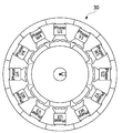
도 2는 본 발명의 실시예에 따른 모터로서, 제1버스바 및 제2버스바의 배치 구조를 설명하기 위한 평면도이다.
도 3은 본 발명의 실시예에 따른 모터로서, 제2버스바를 설명하기 위한 평면도이다.
도 4는 본 발명의 실시예에 따른 모터로서, 제2버스바의 상터미널을 설명하기 위한 평면도이다.
도 5는 본 발명의 실시예에 따른 모터로서, 제1버스바를 설명하기 위한 평면도이다.
도 6은 본 발명의 실시예에 따른 모터로서, 제1버스바의 중성터미널을 설명하기 위한 도면이다.
도 7은 본 발명의 실시예에 따른 모터로서, 코일의 권선 구조를 설명하기 위한 도면이다.
도 8은 본 발명의 실시예에 따른 모터로서, 제어 회로를 설명하기 위한 도면이다.
도 9는 본 발명의 실시예에 따른 모터로서, 제2버스바와 파워터미널의 연결구조를 설명하기 위한 도면이다.
도 10은 본 발명에 따른 모터로서, 스테이터의 코일과 파워터미널의 연결구조를 설명하기 위한 도면이다.
도 11은 본 발명에 따른 모터로서, 제1버스바의 지지구조를 설명하기 위한 도면이다.1 is a cross-sectional view of a motor according to an embodiment of the present invention.
2 is a plan view illustrating an arrangement structure of a first bus bar and a second bus bar as a motor according to an embodiment of the present invention.
3 is a plan view illustrating a second bus bar as a motor according to an embodiment of the present invention.
4 is a plan view illustrating an upper terminal of a second bus bar as a motor according to an embodiment of the present invention.
5 is a plan view illustrating a first bus bar as a motor according to an embodiment of the present invention.
6 is a view for explaining a neutral terminal of a first bus bar as a motor according to an embodiment of the present invention.
7 is a view for explaining a winding structure of a coil as a motor according to an embodiment of the present invention.
8 is a diagram for explaining a control circuit as a motor according to an embodiment of the present invention.
9 is a view for explaining a connection structure between a second bus bar and a power terminal as a motor according to an embodiment of the present invention.
10 is a view for explaining a connection structure between a coil of a stator and a power terminal as a motor according to the present invention.
11 is a view for explaining a support structure of a first bus bar as a motor according to the present invention.
이하, 첨부된 도면을 참조하여 본 발명의 바람직한 실시예를 상세히 설명한다.Hereinafter, preferred embodiments of the present invention will be described in detail with reference to the accompanying drawings.
다만, 본 발명의 기술사상은 설명되는 일부 실시예에 한정되는 것이 아니라 서로 다른 다양한 형태로 구현될 수 있고, 본 발명의 기술사상 범위 내에서라면, 실시예들간 그 구성요소들 중 하나 이상을 선택적으로 결합, 치환하여 사용할 수 있다.However, the technical idea of the present invention is not limited to some embodiments described, but may be implemented in various different forms, and within the scope of the technical idea of the present invention, one or more of the components between the embodiments may be selected It can be combined and substituted with
또한, 본 발명의 실시예에서 사용되는 용어(기술 및 과학적 용어를 포함)는, 명백하게 특별히 정의되어 기술되지 않는 한, 본 발명이 속하는 기술분야에서 통상의 지식을 가진 자에게 일반적으로 이해될 수 있는 의미로 해석될 수 있으며, 사전에 정의된 용어와 같이 일반적으로 사용되는 용어들은 관련 기술의 문맥상의 의미를 고려하여 그 의미를 해석할 수 있을 것이다.In addition, terms (including technical and scientific terms) used in the embodiments of the present invention may be generally understood by those of ordinary skill in the art to which the present invention pertains, unless specifically defined and described explicitly. It may be interpreted as a meaning, and generally used terms such as terms defined in advance may be interpreted in consideration of the contextual meaning of the related art.
또한, 본 발명의 실시예에서 사용된 용어는 실시예들을 설명하기 위한 것이며 본 발명을 제한하고자 하는 것은 아니다.In addition, the terms used in the embodiments of the present invention are for describing the embodiments and are not intended to limit the present invention.
본 명세서에서, 단수형은 문구에서 특별히 언급하지 않는 한 복수형도 포함할 수 있고, "A 및(와) B, C 중 적어도 하나(또는 한 개 이상)"로 기재되는 경우 A, B, C로 조합할 수 있는 모든 조합 중 하나 이상을 포함할 수 있다.In the present specification, the singular form may also include the plural form unless otherwise specified in the phrase, and when it is described as "at least one (or one or more) of A and (and) B, C", it is combined with A, B, C It may include one or more of all possible combinations.
또한, 본 발명의 실시예의 구성요소를 설명하는데 있어서, 제1, 제2, A, B, (a), (b) 등의 용어를 사용할 수 있다.In addition, in describing the components of the embodiment of the present invention, terms such as first, second, A, B, (a), (b), etc. may be used.
이러한 용어는 그 구성요소를 다른 구성요소와 구별하기 위한 것일 뿐, 그 용어에 의해 해당 구성요소의 본질이나 차례 또는 순서 등으로 한정되지 않는다.These terms are only for distinguishing the elements from other elements, and are not limited to the essence, order, or order of the elements by the terms.
그리고, 어떤 구성요소가 다른 구성요소에 '연결', '결합' 또는 '접속'된다고 기재된 경우, 그 구성요소는 그 다른 구성요소에 직접적으로 연결, 결합 또는 접속되는 경우뿐만 아니라, 그 구성요소와 그 다른 구성요소 사이에 있는 또 다른 구성요소로 인해 '연결', '결합' 또는 '접속'되는 경우도 포함할 수 있다.And, if it is described that a component is 'connected', 'coupled' or 'connected' to another component, the component is not only directly connected, coupled or connected to the other component, but also with the component It may also include a case of 'connected', 'coupled' or 'connected' due to another element between the other elements.
또한, 각 구성요소의 "상(위) 또는 하(아래)"에 형성 또는 배치되는 것으로 기재되는 경우, 상(위) 또는 하(아래)는 두 개의 구성요소들이 서로 직접 접촉되는 경우뿐만 아니라 하나 이상의 또 다른 구성요소가 두 개의 구성요소들 사이에 형성 또는 배치되는 경우도 포함한다. 또한, "상(위) 또는 하(아래)"으로 표현되는 경우 하나의 구성요소를 기준으로 위쪽 방향뿐만 아니라 아래쪽 방향의 의미도 포함할 수 있다.In addition, when it is described as being formed or disposed on "above (above) or under (below)" of each component, the upper (above) or lower (below) is one as well as when two components are in direct contact with each other. Also includes a case in which the above another component is formed or disposed between two components. In addition, when expressed as "upper (upper) or lower (lower)", the meaning of not only an upper direction but also a lower direction based on one component may be included.
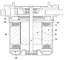
도 1 내지 도 9를 참조하면, 본 발명의 실시예에 따른 모터는, 하우징(50), 하우징(50)의 내부에 배치되는 스테이터(30), 스테이터(30)의 내부에 배치되는 로터(20), 스테이터(30)의 하부에 배치되는 제1버스바(80), 및 스테이터(30)의 상부에 배치되는 제2버스바(40)를 포함한다.1 to 9 , the motor according to the embodiment of the present invention includes a
하우징(50)은 내부에 수용 공간을 갖도록 마련되며, 하우징(50)의 내부에는 스테이터(30) 및 로터(20)가 배치된다.The
로터(20)에는 샤프트(10)가 결합될 수 있으며, 전류 공급을 통해 로터(20)와 스테이터(30)에 전자기적 상호 작용이 발생하면, 로터(20)가 회전하고 이에 연동하여 샤프트(10)가 회전한다. 일 예로, 샤프트(10)는 차량의 조향축(미도시)과 연결되어 조향축에 동력을 전달할 수 있다.A
로터(20)는 스테이터(30)의 내부에 회전 가능하게 배치되며, 스테이터(30)와 전기적 상호 작용을 통해 회전한다. The
로터(20)는 로터(20) 코어와 마그넷을 포함할 수 있다. 일 예로, 로터(20) 코어는 원형의 얇은 강판 형태의 복수개의 플레이트가 적층된 형상으로 실시되거나 또는 하나의 통 형태로 실시될 수 있다.The
로터(20) 코어의 중심에는 샤프트(10)가 결합하는 홀(미도시)이 배치될 수 있다. 로터(20) 코어의 외주면에는 마그넷(미도시)을 가이드 하는 돌기(미도시)가 돌출될 수 있다. 마그넷은 로터(20) 코어의 외주면에 부착될 수 있다. 복수개의 마그넷은 일정 간격으로 로터(20) 코어의 둘레를 따라 배치될 수 있다.A hole (not shown) to which the
또한, 로터(20)는 마그넷을 둘러싸서 마그넷이 로터(20) 코어에서 이탈되지 않도록 고정시키며 마그넷이 노출되는 것을 막는 캔부재(미도시)를 포함할 수 있다.In addition, the
스테이터(30)는 로터(20)와 전기적 상호 작용을 유발하기 위해 코일(31)이 감길 수 있다.The
코일(31)을 감기 위한 스테이터(30)의 구체적인 구성은 다음과 같다. 스테이터(30)는 복수개의 티스(미도시)를 포함하는 스테이터(30) 코어(미도시)를 포함할 수 있다. 스테이터(30) 코어는 환형의 요크(미도시) 부분이 마련되고, 요크에서 중심방향으로 코일(31)이 감기는 티스가 마련될 수 있다. 티스는 요크 부분의 외주면을 따라 일정한 간격으로 마련될 수 있다. 한편, 스테이터(30) 코어는 얇은 강판 형태의 복수개의 플레이트가 상호 적층되어 이루어질 수 있다. 또한, 스테이터(30) 코어는 복수개의 분할 코어가 상호 결합되거나 연결되어 이루어질 수 있다.A specific configuration of the
또한, 하우징의 내부에는 로터(20)와 연동 가능하게 샤프트(10)에 결합되는 센싱 마그넷(60)이 마련된다. 센싱 마그넷(60)은 로터(20)의 위치를 검출하기 위한 장치이다.In addition, a
인쇄회로기판(70)에는 센싱 마그넷(60)의 자기력을 감지하는 센서가 배치될 수 있다. 일 예로, 센서는 홀 IC(Hall IC)일 수 있다. 센서는 센싱 마그넷(60)의 N극과 S극의 변화를 감지하여 센싱 시그널을 생성한다.A sensor for sensing the magnetic force of the
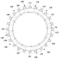
제2버스바(40)는 스테이터(30)의 코일(31)과 접속하며 회로적으로 분리되는 복수개의 터미널 모듈(110,120,130,140), 및 제2바디(42)를 포함하고, 스테이터(30)의 상부에 배치될 수 있다.The
일 예로, 제2버스바(40)는 환형의 제2바디(42) 내부에 복수개의 터미널 모듈을 포함하는 구조로 형성될 수 있으며, 제2버스바(40)의 상부에는 전원인 인가되는 파워터미날(PT)이 연결된다.(도 9 참조)For example, the
제2바디(42)는 사출 성형을 통해 형성된 몰드물이다. 제2바디(42)는 중심부에 홀(미도시)을 포함한다. 복수개의 터미널 모듈(110,120,130,140)은 제2바디(42)의 내부에 배치되며, 터미널 모듈(110,120,130,140)의 단부 일부는 제2바디(42)의 외부로 노출되도록 배치된다. 아울러, 제2바디(42)는 복층 구조이거나 단층 구조일 수 있다.The
제2버스바(40)는, 회로적으로 분리되는 복수개의 터미널 모듈(110,120,130,140)을 구성하도록 마련되어, 각각 U,V,W 상의 전원과 연결되는 복수개의 상터미널을 포함한다.The
참고로, 본 발명의 실시예에서 복수개의 터미널 모듈(110,120,130,140)이 회로적으로 분리된다 함은, 복수개의 터미널 모듈(110,120,130,140)이 각각 스테이터(30)의 코일(31)과 연결되나, 회로적으로 분리되어 서로 독립적인 모터 제어 회로를 구성하는 것으로 정의된다.(도 7 및 도 8 참조)For reference, in the embodiment of the present invention, the plurality of
본 발명의 바람직한 실시예에 따르면, 제2버스바(40)는 회로적으로 분리되는 제1터미널 모듈(110), 제2터미널 모듈(120), 제3터미널 모듈(130), 제4터미널 모듈(140)을 포함한다.(도 2 및 도 8 참조)According to a preferred embodiment of the present invention, the
참고로, 본 발명의 실시예에서는 제2버스바(40)가 회로적으로 분리되는 4개의 터미널 모듈을 포함하여 구성된 예를 들어 설명하고 있지만, 본 발명의 다른 실시예에 따르면, 터미널 유닛이 회로적으로 분리되는 3개 이하의 터미널 모듈을 포함하거나, 5개 이상의 터미널 모듈을 포함하여 구성되는 것도 가능하다.For reference, in the embodiment of the present invention, the
제1터미널 모듈(110), 제2터미널 모듈(120), 제3터미널 모듈(130), 제4터미널 모듈(140)은 스테이터(30)의 중심(또는 제2버스바의 중심)을 기준으로 회전 대칭되게 배치된다.The
참고로, 제1터미널 모듈(110), 제2터미널 모듈(120), 제3터미널 모듈(130), 제4터미널 모듈(140)은, 샤프트(10)의 축 방향을 따라 서로 동일한 층을 이루도록 배치되거나, 서로 다른 층을 이루도록 배치될 수 있다. 이하에서는 제1터미널 모듈(110), 제2터미널 모듈(120), 제3터미널 모듈(130), 제4터미널 모듈(140)이 단일층 상에 배치되는 예를 들어 설명하기로 한다.For reference, the
바람직하게, 제1터미널 모듈(110), 제2터미널 모듈(120), 제3터미널 모듈(130), 제4터미널 모듈(140)은 스테이터(30)의 중심(C1)을 기준으로 90도 간격으로 회전 대칭되게 배치된다.Preferably, the
이는 각 터미널 모듈(110,120,130,140)의 제작 공정을 간소화하고, 제조 원가를 절감하기 위함이다.This is to simplify the manufacturing process of each
즉, 회로적으로 분리된 복수개의 터미널 모듈(110,120,130,140)을 제작하기 위해서는, 각 터미널 모듈의 위치 별로 서로 다른 형상을 갖는 다양한 터미널이 마련되어야 하는데, 여러 종류의 터미널을 제작하기 위해서는 불가피하게 터미널을 제작하기 위한 금형의 개수도 증가하므로, 제작 공정이 복잡하고, 제조 원가가 증가하는 문제점이 있다.That is, in order to manufacture a plurality of circuitly separated
하지만, 실시예는 단 한 종류의 터미널 모듈을 공통적으로 사용하여, 회로적으로 분리된 복수개의 터미널 모듈(110,120,130,140)을 제작할 수 있으므로, 터미널 모듈(110,120,130,140)을 제작하기 위한 금형의 개수를 최소화할 수 있으며, 제작 공정을 간소화하고 제조 원가를 절감하는 유리한 효과를 얻을 수 있다.However, since the embodiment uses only one type of terminal module in common, it is possible to manufacture a plurality of circuitly separated
보다 구체적으로, 제1터미널 모듈(110)은 3개의 상터미널을 포함하고, 제2터미널 모듈(120)은 3개의 상터미널을 포함하고, 제3터미널 모듈(130)은 3개의 상터미널을 포함하고, 제4터미널 모듈(140)은 3개의 상터미널을 포함한다.More specifically, the
일 예로, 제1터미널 모듈(110)은, 스테이터(30)의 중심(C1)을 기준으로 30도 간격으로 이격되게 배치되는 제1-1상터미널(112)(예를 들어, U1상), 제1-2상터미널(114)(예를 들어, V1상), 제1-3상터미널(116)(예를 들어, W1상)을 포함한다.As an example, the
제2터미널 모듈(120)은, 상기 스테이터(30)의 중심(C1)을 기준으로 30도 간격으로 이격되게 배치되는 제2-1상터미널(122)(예를 들어, U2상), 제2-2상터미널(124)(예를 들어, V2상), 제2-3상터미널(126)(예를 들어, W2상)을 포함한다.The
제3터미널 모듈(130)은, 스테이터(30)의 중심(C1)을 기준으로 30도 간격으로 이격되게 배치되는 제3-1상터미널(132)(예를 들어, U3상), 제3-2상터미널(134)(예를 들어, V3상), 제3-3상터미널(136)(예를 들어, W3상)을 포함한다.The third
제4터미널 모듈(140)은, 스테이터(30)의 중심(C1)을 기준으로 30도 간격으로 이격되게 배치되는 제4-1상터미널(142)(예를 들어, U4상), 제4-2상터미널(144)(예를 들어, V4상), 제4-3상터미널(146)(예를 들어, W4상)을 포함한다.The fourth
도 2를 참조하면, 제1-1상터미널(112)은 스테이터(30)의 중심(C1)을 기준으로 12시 방향(도 2 기준)에 배치되고, 제1-2상터미널(114)은 스테이터(30)의 중심(C1)을 기준으로 제1-1상터미널(112)과 30도 이격되게 배치되고, 제1-3상터미널(116)은 스테이터(30)의 중심(C1)을 기준으로 제1-2상터미널(114)과 30도 이격되게 배치된다. 일 예로, 제1-1상터미널(112), 제1-2상터미널(114) 및 제1-3상터미널(116)은, 스테이터(30)의 중심(C1)을 지나는 직교축(x축, y축)을 기준으로 구획되는 사분면 영역 중에, 제1사분면(first quadrant) 영역에 배치될 수 있다.2, the phase 1-1
제2-1상터미널(122)은, 스테이터(30)의 중심(C1)을 기준으로 3시 방향에 (도 2 기준)배치되고, 제2-2상터미널(124)은 스테이터(30)의 중심(C1)을 기준으로 제2-1상터미널(122)과 30도 이격되게 배치되고, 제2-3상터미널(126)은 스테이터(30)의 중심(C1)을 기준으로 제2-2상터미널(124)과 30도 이격되게 배치된다. 일 예로, 제2-1상터미널(122), 제2-2상터미널(124) 및 제2-3상터미널(126)은, 스테이터(30)의 중심(C1)을 지나는 직교축(x축, y축)을 기준으로 구획되는 사분면 영역 중에, 제4사분면(fourth quadrant) 영역에 배치될 수 있다.Phase 2-1
제3-1상터미널(132)은, 스테이터(30)의 중심(C1)을 기준으로 6시 방향(도 2 기준)에 배치되고, 제3-2상터미널(134)은 스테이터(30)의 중심(C1)을 기준으로 제3-1상터미널(132)과 30도 이격되게 배치되고, 제3-3상터미널(136)은 스테이터(30)의 중심(C1)을 기준으로 제3-2상터미널(134)과 30도 이격되게 배치된다. 일 예로, 제3-1상터미널(132), 제3-2상터미널(134) 및 제3-3상터미널(136)은, 스테이터(30)의 중심(C1)을 지나는 직교축(x축, y축)을 기준으로 구획되는 사분면 영역 중에, 제3사분면(third quadrant) 영역에 배치될 수 있다.The phase 3-1
제4-1상터미널(142)은, 스테이터(30)의 중심(C1)을 기준으로 9시 방향(도 2 기준)에 배치되고, 제4-2상터미널(144)은 스테이터(30)의 중심(C1)을 기준으로 제4-1상터미널(142)과 30도 이격되게 배치되고, 제4-3상터미널(146)은 스테이터(30)의 중심(C1)을 기준으로 제4-2상터미널(144)과 30도 이격되게 배치된다. 일 예로, 제4-1상터미널(142), 제4-2상터미널(144) 및 제4-3상터미널(146)은, 스테이터(30)의 중심(C1)을 지나는 직교축(x축, y축)을 기준으로 구획되는 사분면 영역 중에, 제2사분면(second quadrant) 영역에 배치될 수 있다.The 4-1
보다 구체적으로, 제1-1상터미널(112)은 스테이터(30)의 중심(C1)을 기준으로 12시 방향에 배치되고, 시계 방향을 따라 30도 간격으로 이격되게 제1-2상터미널(114), 제1-3상터미널(116), 제2-1상터미널(122), 제2-2상터미널(124), 제2-3상터미널(126), 제3-1상터미널(132), 제3-2상터미널(134), 제3-3상터미널(136), 제4-1상터미널(142), 제4-2상터미널(144) 및 제4-3상터미널(146)이 순차적으로 배치된다.More specifically, the phase 1-1
바람직하게, 제1-1상터미널(112), 제1-2상터미널(114), 제1-3상터미널(116), 제2-1상터미널(122), 제2-2상터미널(124), 제2-3상터미널(126), 제3-1상터미널(132), 제3-2상터미널(134), 제3-3상터미널(136), 제4-1상터미널(142), 제4-2상터미널(144) 및 제4-3상터미널(146)은 서로 동일한 구조(동일한 형상)로 형성된다. 따라서, 하나의 금형을 공통적으로 사용하여 서로 다른 4개의 독립적인 터미널 모듈을 구성하는 복수개의 상터미널을 제조할 수 있으므로, 제조 공정이 단순하고, 제조 비용이 줄어드는 이점이 있다.Preferably, the phase 1-1
도 4를 참조하면, 복수개의 상터미널(제1-1상터미널, 제1-2상터미널, 제1-3상터미널, 제2-1상터미널, 제2-2상터미널, 제2-3상터미널, 제3-1상터미널, 제3-2상터미널, 제3-3상터미널, 제4-1상터미널, 제4-2상터미널 및 제4-3상터미널)은 각각, 상터미널 몸체(101), 및 스테이터(30)의 반경 방향을 따라 상터미널 몸체(101)에서 연장되는 상터미널 돌출부(102)를 포함한다. 이하에서는, 제1-1상터미널(112)을 기준으로 상터미널 몸체(101)와 상터미널 돌출부(102)를 설명하기로 한다.4, a plurality of phase terminals (phase 1-1 terminal, phase 1-2 terminal, phase 1-3 terminal, phase 2-1 terminal, phase 2-2 terminal, phase 2-3 Phase Terminal, Phase 3-1 Terminal, Phase 3-2 Terminal, Phase 3-3 Terminal, Phase 4-1 Terminal, Phase 4-2, and Phase 4-3 Terminal) are, respectively, phase terminals It includes a
상터미널 몸체(101)는 직선 형태의 띠형 부재(또는 소정 곡률을 갖는 원호 형상의 띠형 부재)로 형성될 수 있다. 상터미널 몸체(101)와 상터미널 돌출부(102)는 그 형상 및 기능적 특성에 따라 구분되어 설명될 수 있을 뿐, 일체로 연결된 하나의 부재일 수 있다.The upper
일 예로, 제1-1상터미널(112)의 상터미널 몸체(101)는 직선 형태의 띠형 부재로 형성될 수 있다.For example, the upper
상터미널 돌출부(102)는 스테이터(30)의 반경 방향을 따라 상터미널 몸체(101)에 연장되며 제1바디(82)의 외측으로 돌출된다. 상터미널 돌출부(102)의 단부는 갈고리와 같이 절곡된 형태로 형성된다.The upper
상터미널 돌출부(102)는 스테이터(30)의 코일(31)과 전기적으로 연결된다. 일 예로, 상터미널 돌출부(102)는 스테이터(30)의 코일(31)과 퓨징(fusing)될 수 있다.The upper
상터미널 몸체(101)와 상터미널 돌출부(102)는 단일층 구조로 형성되거나, 이중층 구조(복층 구조)을 이루도록 형성될 수 있으며, 상터미널 몸체(101)와 상터미널 돌출부(102)의 연결 구조에 의해 본 발명이 제한되거나 한정되는 것은 아니다.The upper
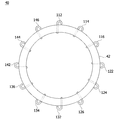
제1버스바(80)는 스테이터(30)의 하부에 배치되고, 스테이터(30)의 코일(31)과 접속하며 회로적으로 분리되는 복수개의 중성터미널(118,128,138,148) 및 제1바디(82)를 포함한다.The
일 예로, 제1버스바(80)는 환형의 제1바디(82) 내부에 복수개의 중성터미널(118,128,138,148)을 포함하는 구조로 형성될 수 있다.For example, the
제1바디(82)는 사출 성형을 통해 형성된 몰드물이다. 제1바디(82)는 중심부에 홀(미도시)을 포함한다. 중성터미널은 제1바디(82)의 내부에 배치되며, 중성터미널의 단부의 일부는 제1바디(82)의 외부로 노출되도록 배치된다. 아울러, 제1바디(82)는 복층 구조이거나 단층 구조일 수 있다.The
이는, 버스바(제1버스바 또는 제2버스바)의 구조 및 제작 공정을 간소화하고, 스테이터의 하부에 존재하는 여유 공간을 이용하여 중성터미널(118,128,138,148)을 배치하기 위함이다.This is to simplify the structure and manufacturing process of the bus bar (the first bus bar or the second bus bar), and to arrange the
즉, 실시예는 회로적으로 분리되는 복수개의 터미널 모듈을 구성하기 위한 상터미널과 중성터미널을 구조적으로 분리시켜, 중성터미널은 제1버스바(80)에 포함되고, 상터미널은 제2버스바(40)에 포함되도록 하는 것에 의하여, 제1버스바(80) 및 제2버스바(40)의 구조 및 제작 공정을 간소화하는 유리한 효과를 얻을 수 있다.That is, the embodiment structurally separates the upper terminal and the neutral terminal for configuring a plurality of terminal modules that are circuitly separated, the neutral terminal is included in the
더욱이, 중성터미널을 포함하는 제1버스바(80)를 스테이터의 하부에 존재하는 여유 공간(스테이터의 하부와 하우징의 사이 공간)에 배치하는 것에 의하여, 스테이터의 상부 영역의 공간활용성을 높이고 설계 자유도를 향상시킬 수 있으며, 복수개의 모터 제어 회로를 구현하기 위한 제1버스바(80) 및 제2버스바(40)를 모터의 내부에 보다 용이하게 배치할 수 있다. 따라서, 복수개의 모터 제어 회로를 구현하기 위한 상터미널 및 중성터미널이 탑재됨에 따른 모터의 크기 증가를 최소화하고 모터의 소형화에 기여하는 유리한 효과를 얻을 수 있다.Furthermore, by arranging the
도 5를 참조하면, 복수개의 중성터미널(118,128,138,148)은 스테이터(30)의 중심을 기준으로 회전 대칭되게 배치된다.Referring to FIG. 5 , the plurality of
본 발명의 바람직한 실시예에 따르면, 제1버스바(80)는 회로적으로 분리되는 제1중성터미널(118), 제2중성터미널(128), 제3중성터미널(138), 제4중성터미널(148)을 포함할 수 있다.According to a preferred embodiment of the present invention, the
보다 구체적으로, 제1중성터미널(118)은 제1터미널 모듈(110)과 회로적으로 연결되고, 제2중성터미널(128)은 제2터미널 모듈(120)과 회로적으로 연결되고, 제3중성터미널(138)은 제3터미널 모듈(130)과 회로적으로 연결되고, 제4중성터미널(148)은 제4터미널 모듈(140)과 회로적으로 연결된다.More specifically, the first
바람직하게, 제1중성터미널(118), 제2중성터미널(128), 제3중성터미널(138), 제4중성터미널(148)은 스테이터(30)의 중심(C1)을 기준으로 90도 간격으로 회전 대칭되게 배치된다.Preferably, the first
이와 같이, 한 종류의 중성터미널을 공통적으로 사용하여, 회로적으로 분리된 복수개의 터미널 모듈을 구성할 수 있으므로, 복수개의 터미널 모듈을 제작하기 위한 금형의 개수를 최소화할 수 있으며, 제작 공정을 간소화하고 제조 원가를 절감하는 유리한 효과를 얻을 수 있다.As described above, by using one type of neutral terminal in common, it is possible to configure a plurality of terminal modules separated in circuit, so that the number of molds for manufacturing the plurality of terminal modules can be minimized, and the manufacturing process is simplified. and can obtain advantageous effects of reducing the manufacturing cost.
보다 구체적으로, 제1중성터미널(118)은 제1-1상터미널(112)(예를 들어, U1상), 제1-2상터미널(114)(예를 들어, V1상), 제1-3상터미널(116)(예를 들어, W1상)을 전기적으로 연결한다. 일 예로, 제1중성터미널(118)은, 스테이터(30)의 중심(C1)을 지나는 직교축(x축, y축)을 기준으로 구획되는 사분면 영역 중에, 제1사분면 영역에 배치될 수 있다.More specifically, the first
제2중성터미널(128)은 제2-1상터미널(122)(예를 들어, U2상), 제2-2상터미널(124)(예를 들어, V2상), 제2-3상터미널(126)(예를 들어, W2상)을 전기적으로 연결한다. 일 예로, 제2중성터미널(128)은, 스테이터(30)의 중심(C1)을 지나는 직교축(x축, y축)을 기준으로 구획되는 사분면 영역 중에, 제4사분면 영역에 배치될 수 있다.The second
제3중성터미널(138)은 제3-1상터미널(132)(예를 들어, U3상), 제3-2상터미널(134)(예를 들어, V3상), 제3-3상터미널(136)(예를 들어, W3상)을 전기적으로 연결한다. 일 예로, 제3중성터미널(138)은 스테이터(30)의 중심(C1)을 지나는 직교축(x축, y축)을 기준으로 구획되는 사분면 영역 중에, 제3사분면 영역에 배치될 수 있다.The third
제4중성터미널(148)은 제4-1상터미널(142)(예를 들어, U4상), 제4-2상터미널(144)(예를 들어, V4상), 제4-3상터미널(146)(예를 들어, W4상)을 전기적으로 연결한다. 일 예로, 제4중성터미널(148)은 스테이터(30)의 중심(C1)을 지나는 직교축(x축, y축)을 기준으로 구획되는 사분면 영역 중에, 제2사분면 영역에 배치될 수 있다.The fourth
바람직하게, 제1중성터미널(118), 제2중성터미널(128), 제3중성터미널(138), 제4중성터미널(148)은 서로 동일한 구조(동일한 형상)로 형성된다. 따라서, 하나의 금형을 공통적으로 사용하여 서로 다른 4개의 독립적인 터미널 모듈을 구성하는 복수개의 중성터미널을 제조할 수 있으므로, 제조 공정이 단순하고, 제조 비용이 줄어드는 이점이 있다.Preferably, the first
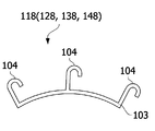
도 6을 참조하면, 제1중성터미널(118), 제2중성터미널(128), 제3중성터미널(138), 제4중성터미널(148)은 각각, 중성터미널 몸체(103) 및 스테이터(30)의 반경 방향을 따라 중성터미널 몸체(103)에서 연장되는 중성터미널 돌출부(104)를 포함한다.Referring to FIG. 6 , the first
중성터미널 몸체(103)는 곡면을 갖는 띠형 부재로 형성될 수 있다. 중성터미널 몸체(103)와 중성터미널 돌출부(104)는 그 형상 및 기능적 특성에 따라 구분되어 설명될 수 있을 뿐, 일체로 연결된 하나의 부재일 수 있다.The neutral
일 예로, 제1중성터미널(118), 제2중성터미널(128), 제3중성터미널(138), 제4중성터미널(148)의 중성터미널 몸체(103)는 소정 곡률을 갖는 원호 형상의 띠형 부재로 형성될 수 있다.For example, the neutral
중성터미널 돌출부(104)는 스테이터(30)의 반경 방향을 따라 중성터미널 몸체(103)에 연장되며 제1바디(82)의 외측으로 돌출된다. 중성터미널 몸체(103)에는 3개의 중성터미널 돌출부(104)가 마련되고, 중성터미널 돌출부(104)의 단부는 갈고리와 같이 절곡된 형태로 형성된다.The neutral
중성터미널 돌출부(104)는 U,V,W 상의 전원과 연결되는 스테이터(30)의 코일(31)과 전기적으로 연결된다. 일 예로, 중성터미널 돌출부(104)는 스테이터(30)의 코일(31)과 퓨징(fusing)될 수 있다.The neutral
중성터미널 몸체(103)와 중성터미널 돌출부(104)는 단일층 구조로 형성되거나, 이중층 구조(복층 구조)을 이루도록 형성될 수 있으며, 중성터미널 몸체(103)와 중성터미널 돌출부(104)의 연결 구조에 의해 본 발명이 제한되거나 한정되는 것은 아니다.The neutral
한편, 전술 및 도시한 본 발명의 실시예에서는 모터가 제1버스바(80) 및 제2버스바(40)를 모두 포함하고, 파워터미날(PT)이 연결되는 제2버스바(40)를 매개로 코일에 전원이 인가되는 예를 들어 설명하고 있지만, 본 발명의 다른 실시예에 따르면, 별도의 제2버스바를 사용하지 않고 파워터미널이 코일에 직접 연결되도록 구성하는 것도 가능하다.On the other hand, in the above and illustrated embodiments of the present invention, the motor includes both the
도 10을 참조하면, 모터는, 하우징(50), 하우징(50)의 내부에 배치되는 스테이터(30), 스테이터(30)의 내부에 배치되는 로터(20), 및 스테이터(30)의 하부에 배치되는 제1버스바(80)만을 포함하고, 전술한 제2버스바(도 9의 40 참조)는 포함하지 않는다.Referring to FIG. 10 , the motor includes a
스테이터(30)의 코일에는 U상, V상 ,W상의 전원을 인가하는 파워터미날(PT)이 직접 연결될 수 있으며, 제1버스바(80)는 스테이터(30)의 코일(31)과 접속하며 회로적으로 분리되는 복수개의 중성터미널(도 5의 118,128,138,148 참조)을 포함한다.A power terminal (PT) for applying power of U-phase, V-phase, and W-phase may be directly connected to the coil of the
이와 같이, 실시예는 회로적으로 분리되는 복수개의 터미널 모듈을 구성하기 위한 상터미널(제2버스바)을 마련하지 않아도 되므로, 제1버스바(80)의 구조 및 제작 공정을 간소화하는 유리한 효과를 얻을 수 있다.As described above, in the embodiment, since it is not necessary to provide an upper terminal (second bus bar) for configuring a plurality of terminal modules that are circuitly separated, it is advantageous to simplify the structure and manufacturing process of the
더욱이, 중성터미널을 포함하는 제1버스바(80)를 스테이터(30)의 하부에 배치하는 것에 의하여, 스테이터(30)의 상부 영역의 공간활용성을 높이고 설계 자유도를 향상시킬 수 있으며, 복수개의 모터 제어 회로를 구현하기 위한 제1버스바(80)를 모터의 내부에 보다 용이하게 배치할 수 있다. 따라서, 복수개의 모터 제어 회로를 구현하기 위한 중성터미널이 탑재됨에 따른 모터의 크기 증가를 최소화하고 모터의 소형화에 기여하는 유리한 효과를 얻을 수 있다.Furthermore, by disposing the
또한, 도 11을 참조하면, 본 발명의 바람직한 실시예에 따르면, 제1버스바(80)는 하우징(50)의 내측면에 지지된다.Also, referring to FIG. 11 , according to a preferred embodiment of the present invention, the
이와 같이, 제1버스바(80)가 하우징(50)의 내측면에 지지되도록 하는 것에 의하여, 모터의 구동 중에 제1버스바(80)의 떨림을 억제하고, 진동 및 소음을 최소화하는 유리한 효과를 얻을 수 있다.In this way, by allowing the
제1버스바(80)는 요구되는 조건 및 설계 사양에 따라 다양한 방식으로 하우징의 내측면에 지지될 수 있다.The
일 예로, 제1바디(82)는 제1내면(82a) 및 제1외면(82b)을 포함하고, 제1외면(82b)은 하우징(50)의 내측면에 밀착되게 지지된다.For example, the
바람직하게, 중성터미널 돌출부(104)는 제1내면(82a)으로 돌출된다. 이와 같이, 중성터미널 돌출부(104)가 제1바디(82)의 제1내면(82a)으로 돌출되게 하는 것에 의하여, 중성터미널 돌출부(104)에 의한 간섭없이 제1바디(82)의 제1외면(82b)을 하우징(50)의 내측면에 밀착시키는 유리한 효과를 얻을 수 있다.Preferably, the neutral
이상으로 본 발명의 바람직한 하나의 실시예에 따른 모터에 관하여 첨부된 도면을 참조하여 구체적으로 살펴보았다.As described above, the motor according to a preferred embodiment of the present invention has been described in detail with reference to the accompanying drawings.
이상의 설명은 본 발명의 기술 사상을 예시적으로 설명한 것에 불과한 것으로서, 본 발명이 속하는 기술 분야에서 통상의 지식을 가진 자라면 본 발명의 본질적인 특성에서 벗어나지 않는 범위 내에서 다양한 수정, 변경 및 치환이 가능할 것이다. 따라서, 본 발명에 개시된 실시예 및 첨부된 도면들은 본 발명의 기술 사상을 한정하기 위한 것이 아니라 설명하기 위한 것이고, 이러한 실시예 및 첨부된 도면에 의하여 본 발명의 기술 사상의 범위가 한정되는 것은 아니다. 본 발명의 보호 범위는 아래의 청구범위에 의하여 해석되어야 하며, 그와 동등한 범위 내에 있는 모든 기술 사상은 본 발명의 권리범위에 포함되는 것으로 해석되어야 할 것이다.The above description is merely illustrative of the technical idea of the present invention, and various modifications, changes, and substitutions are possible within the range that does not depart from the essential characteristics of the present invention by those of ordinary skill in the art to which the present invention pertains. will be. Accordingly, the embodiments disclosed in the present invention and the accompanying drawings are for explaining, not limiting, the technical spirit of the present invention, and the scope of the technical spirit of the present invention is not limited by these embodiments and the accompanying drawings. . The protection scope of the present invention should be construed by the following claims, and all technical ideas within the equivalent range should be construed as being included in the scope of the present invention.
10 : 샤프트 20 : 로터
30 : 스테이터 31 : 코일
40 : 제2버스바 42 : 제2바디
50 : 하우징 80 : 제1버스바
82 : 제1바디 101 : 상터미널 몸체
102 : 상터미널 돌출부 103 : 중성터미널 몸체
104 : 중성터미널 돌출부 110 : 제1터미널 모듈
112 : 제1-1상터미널 114 : 제1-2상터미널
116 : 제1-3상터미널 118 : 제1중성터미널
120 : 제2터미널 모듈 122 : 제2-1상터미널
124 : 제2-2상터미널 126 : 제2-3상터미널
128 : 제2중성터미널 130 : 제3터미널 모듈
132 : 제3-1상터미널 134 : 제3-2상터미널
136 : 제3-3상터미널 138 : 제3중성터미널
140 : 제4터미널 모듈 142 : 제4-1상터미널
144 : 제4-2상터미널 146 : 제4-3상터미널
148 : 제4중성터미널10: shaft 20: rotor
30: stator 31: coil
40: second bus bar 42: second body
50: housing 80: first bus bar
82: first body 101: upper terminal body
102: upper terminal protrusion 103: neutral terminal body
104: neutral terminal protrusion 110: first terminal module
112: Phase 1-1 Terminal 114: Phase 1-2 Terminal
116: Phase 1-3 Terminal 118:
120: second terminal module 122: 2-1 phase terminal
124: Phase 2-2 Terminal 126: Phase 2-3 Terminal
128: second neutral terminal 130: third terminal module
132: Phase 3-1 Terminal 134: Phase 3-2 Terminal
136: 3-3 phase terminal 138: 3 neutral terminal
140: 4th terminal module 142: 4-1 phase terminal
144: 4-2 phase terminal 146: 4-3 phase terminal
148 : 4th neutral terminal
Claims (17)
상기 하우징의 내부에 배치되는 스테이터;
상기 스테이터의 내부에 배치되는 로터; 및
상기 스테이터의 하부에 배치되는 제1버스바;를 포함하고,
상기 제1버스바는 상기 스테이터의 코일과 접속하며 회로적으로 분리되는 복수개의 중성터미널을 포함하고,
상기 복수개의 중성터미널은 상기 스테이터의 중심을 기준으로 회전 대칭되게 배치되는 모터.
housing;
a stator disposed inside the housing;
a rotor disposed inside the stator; and
Including; a first bus bar disposed under the stator;
The first bus bar includes a plurality of neutral terminals connected to the coil of the stator and separated in a circuit,
The plurality of neutral terminals are disposed rotationally symmetrically with respect to the center of the stator.
상기 제1버스바는, 제1중성터미널, 제2중성터미널, 제3중성터미널, 및 제4중성터미널을 포함하는 모터.
According to claim 1,
The first bus bar is a motor including a first neutral terminal, a second neutral terminal, a third neutral terminal, and a fourth neutral terminal.
상기 제1중성터미널, 상기 제2중성터미널, 상기 제3중성터미널, 상기 제4중성터미널은 상기 스테이터의 중심을 기준으로 90도 간격으로 회전 대칭되게 배치되는 모터.
3. The method of claim 2,
The first neutral terminal, the second neutral terminal, the third neutral terminal, and the fourth neutral terminal are rotationally symmetrically disposed at intervals of 90 degrees with respect to the center of the stator.
상기 제1중성터미널, 상기 제2중성터미널, 상기 제3중성터미널, 상기 제4중성터미널은 서로 동일한 구조로 형성되는 모터.
4. The method of claim 3,
The first neutral terminal, the second neutral terminal, the third neutral terminal, and the fourth neutral terminal are formed in the same structure as each other.
상기 중성터미널은 각각, 중성터미널 몸체 및 상기 스테이터의 반경 방향을 따라 상기 중성터미널 몸체에서 연장되는 중성터미널 돌출부를 포함하는 모터.
According to claim 1,
The neutral terminal includes a neutral terminal body and a neutral terminal protrusion extending from the neutral terminal body along a radial direction of the stator, respectively.
복수개의 상기 중성터미널을 감싸도록 형성되는 제1바디를 포함하는 모터.
6. The method of claim 5,
A motor including a first body formed to surround the plurality of neutral terminals.
상기 제1버스바는 상기 하우징의 내측면에 지지되는 모터.
7. The method of claim 6,
The first bus bar is a motor supported on the inner surface of the housing.
상기 제1바디는 제1내면 및 제1외면을 포함하고,
상기 제1외면은 상기 하우징의 내측면에 밀착되게 지지되는 모터.
8. The method of claim 7,
The first body includes a first inner surface and a first outer surface,
The first outer surface of the motor is supported in close contact with the inner surface of the housing.
상기 중성터미널 돌출부는 상기 제1내면으로 돌출되는 모터.
9. The method of claim 8,
The motor protruding from the neutral terminal protrusion toward the first inner surface.
상기 스테이터의 상부에 배치되는 제2버스바를 포함하고,
상기 제2버스바는 상기 스테이터의 코일과 접속하며 회로적으로 분리되는 복수개의 터미널 모듈을 포함하고,
상기 터미널 모듈은 각각 복수개의 상터미널을 포함하는 모터.
3. The method of claim 2,
and a second bus bar disposed on the upper part of the stator,
The second bus bar includes a plurality of terminal modules connected to the coil of the stator and separated in a circuit,
The terminal module is a motor including a plurality of phase terminals, respectively.
상기 제2버스바는,
상기 제1중성터미널과 회로적으로 연결되는 제1터미널 모듈, 상기 제2중성터미널과 회로적으로 연결되는 제2터미널 모듈, 상기 제3중성터미널과 회로적으로 연결되는 제3터미널 모듈, 및 상기 제4중성터미널과 회로적으로 연결되는 제4터미널 모듈을 포함하는 모터.
11. The method of claim 10,
The second bus bar,
A first terminal module circuitry connected to the first neutral terminal, a second terminal module circuitry connected to the second neutral terminal, a third terminal module circuitry connected to the third neutral terminal, and the A motor comprising a fourth terminal module circuitly connected to the fourth neutral terminal.
상기 제1터미널 모듈, 상기 제2터미널 모듈, 상기 제3터미널 모듈, 상기 제4터미널 모듈은 상기 스테이터의 중심을 기준으로 회전 대칭되게 배치되는 모터.
12. The method of claim 11,
The first terminal module, the second terminal module, the third terminal module, and the fourth terminal module are rotationally symmetrical with respect to the center of the stator motor.
상기 제1터미널 모듈, 상기 제2터미널 모듈, 상기 제3터미널 모듈, 상기 제4터미널 모듈은 상기 스테이터의 중심을 기준으로 90도 간격으로 회전 대칭되게 배치되는 모터.
13. The method of claim 12,
The first terminal module, the second terminal module, the third terminal module, and the fourth terminal module are rotationally symmetrically disposed at intervals of 90 degrees with respect to the center of the stator.
상기 제1터미널 모듈은, 상기 스테이터의 중심을 기준으로 30도 간격으로 이격되게 배치되는 제1-1상터미널, 제1-2상터미널, 제1-3상터미널을 포함하고,
상기 제2터미널 모듈은, 상기 스테이터의 중심을 기준으로 30도 간격으로 이격되게 배치되는 제2-1상터미널, 제2-2상터미널, 제2-3상터미널을 포함하고,
상기 제3터미널 모듈은, 상기 스테이터의 중심을 기준으로 30도 간격으로 이격되게 배치되는 제3-1상터미널, 제3-2상터미널, 제3-3상터미널을 포함하고,
상기 제4터미널 모듈은, 상기 스테이터의 중심을 기준으로 30도 간격으로 이격되게 배치되는 제4-1상터미널, 제4-2상터미널, 제4-3상터미널을 포함하는 모터.
14. The method of claim 13,
The first terminal module includes a 1-1 phase terminal, a 1-2 phase terminal, and a phase 1-3 terminal which are disposed to be spaced apart at intervals of 30 degrees with respect to the center of the stator,
The second terminal module includes a phase 2-1 terminal, a phase 2-2 terminal, and a phase 2-3 terminal disposed to be spaced apart at intervals of 30 degrees with respect to the center of the stator,
The third terminal module includes a phase 3-1 terminal, a phase 3-2 terminal, and a phase 3-3 terminal disposed to be spaced apart at intervals of 30 degrees with respect to the center of the stator,
The fourth terminal module includes a 4-1 phase terminal, a 4-2 phase terminal, and a 4-3 phase terminal which are spaced apart at intervals of 30 degrees based on the center of the stator.
상기 제1-1상터미널, 상기 제1-2상터미널, 상기 제1-3상터미널, 상기 제2-1상터미널, 상기 제2-2상터미널, 상기 제2-3상터미널, 상기 제3-1상터미널, 상기 제3-2상터미널, 상기 제3-3상터미널, 상기 제4-1상터미널, 상기 제4-2상터미널, 상기 제4-3상터미널은 서로 동일한 구조로 형성되는 모터.
15. The method of claim 14,
The phase 1-1 terminal, the phase 1-2 terminal, the phase 1-3 terminal, the phase 2-1 terminal, the phase 2-2 terminal, the phase 2-3 terminal, the phase 2 terminal The phase 3-1 terminal, the phase 3-2 terminal, the phase 3-3 terminal, the phase 4-1 terminal, the phase 4-2 terminal, and the phase 4-3 terminal have the same structure. motor formed.
상기 상터미널은 각각, 상터미널 몸체 및 상기 스테이터의 반경 방향을 따라 상기 상터미널 몸체에서 연장되는 상터미널 돌출부를 포함하는 모터.
11. The method of claim 10,
Each of the upper terminals includes an upper terminal body and an upper terminal protrusion extending from the upper terminal body along a radial direction of the stator.
복수개의 상기 상터미널을 감싸도록 형성되는 제2몰드를 포함하는 모터.
11. The method of claim 10,
A motor including a second mold formed to surround the plurality of upper terminals.
Priority Applications (4)
| Application Number | Priority Date | Filing Date | Title |
|---|---|---|---|
| KR1020190169009A KR20210077404A (en) | 2019-12-17 | 2019-12-17 | Motor |
| CN202080087375.XA CN114830501A (en) | 2019-12-17 | 2020-11-11 | Motor |
| US17/756,673 US20220385135A1 (en) | 2019-12-17 | 2020-11-11 | Motor |
| PCT/KR2020/015744 WO2021125562A1 (en) | 2019-12-17 | 2020-11-11 | Motor |
Applications Claiming Priority (1)
| Application Number | Priority Date | Filing Date | Title |
|---|---|---|---|
| KR1020190169009A KR20210077404A (en) | 2019-12-17 | 2019-12-17 | Motor |
Publications (1)
| Publication Number | Publication Date |
|---|---|
| KR20210077404A true KR20210077404A (en) | 2021-06-25 |
Family
ID=76629317
Family Applications (1)
| Application Number | Title | Priority Date | Filing Date |
|---|---|---|---|
| KR1020190169009A KR20210077404A (en) | 2019-12-17 | 2019-12-17 | Motor |
Country Status (1)
| Country | Link |
|---|---|
| KR (1) | KR20210077404A (en) |
-
2019
- 2019-12-17 KR KR1020190169009A patent/KR20210077404A/en unknown
Similar Documents
| Publication | Publication Date | Title |
|---|---|---|
| CN111566908B (en) | Motor | |
| JP5217117B2 (en) | Brushless motor | |
| JP4941007B2 (en) | motor | |
| CN109417317B (en) | Stator unit, stator and motor comprising same | |
| JP2016013000A (en) | Motor and electrically-driven power steering device mounting the same | |
| US11909287B2 (en) | Insulator and motor comprising same | |
| KR20150040527A (en) | Motor | |
| CN113273059B (en) | Motor with a motor housing having a motor housing with a motor housing | |
| KR20210077405A (en) | Motor | |
| US11362559B2 (en) | Motor | |
| KR20210077404A (en) | Motor | |
| US20230047704A1 (en) | Motor | |
| US20220385135A1 (en) | Motor | |
| US20230307983A1 (en) | Motor | |
| CN111316542B (en) | Motor | |
| JP5583192B2 (en) | Rotating electric machine stator | |
| JP5798971B2 (en) | Torque sensor | |
| WO2009048181A1 (en) | Motor |