EP3852239A1 - Baugruppe mit orthogonal zur montagerichtung der baugruppe montierbaren steckerverbinder - Google Patents
Baugruppe mit orthogonal zur montagerichtung der baugruppe montierbaren steckerverbinder Download PDFInfo
- Publication number
- EP3852239A1 EP3852239A1 EP21150918.7A EP21150918A EP3852239A1 EP 3852239 A1 EP3852239 A1 EP 3852239A1 EP 21150918 A EP21150918 A EP 21150918A EP 3852239 A1 EP3852239 A1 EP 3852239A1
- Authority
- EP
- European Patent Office
- Prior art keywords
- housing
- assembly
- electronic subassembly
- connector
- contact element
- Prior art date
- Legal status (The legal status is an assumption and is not a legal conclusion. Google has not performed a legal analysis and makes no representation as to the accuracy of the status listed.)
- Withdrawn
Links
Images

Classifications
-
- H—ELECTRICITY
- H02—GENERATION; CONVERSION OR DISTRIBUTION OF ELECTRIC POWER
- H02K—DYNAMO-ELECTRIC MACHINES
- H02K11/00—Structural association of dynamo-electric machines with electric components or with devices for shielding, monitoring or protection
- H02K11/30—Structural association with control circuits or drive circuits
- H02K11/33—Drive circuits, e.g. power electronics
-
- H—ELECTRICITY
- H02—GENERATION; CONVERSION OR DISTRIBUTION OF ELECTRIC POWER
- H02K—DYNAMO-ELECTRIC MACHINES
- H02K5/00—Casings; Enclosures; Supports
- H02K5/04—Casings or enclosures characterised by the shape, form or construction thereof
- H02K5/22—Auxiliary parts of casings not covered by groups H02K5/06-H02K5/20, e.g. shaped to form connection boxes or terminal boxes
- H02K5/225—Terminal boxes or connection arrangements
-
- F—MECHANICAL ENGINEERING; LIGHTING; HEATING; WEAPONS; BLASTING
- F04—POSITIVE - DISPLACEMENT MACHINES FOR LIQUIDS; PUMPS FOR LIQUIDS OR ELASTIC FLUIDS
- F04D—NON-POSITIVE-DISPLACEMENT PUMPS
- F04D29/00—Details, component parts, or accessories
- F04D29/40—Casings; Connections of working fluid
-
- H—ELECTRICITY
- H01—ELECTRIC ELEMENTS
- H01R—ELECTRICALLY-CONDUCTIVE CONNECTIONS; STRUCTURAL ASSOCIATIONS OF A PLURALITY OF MUTUALLY-INSULATED ELECTRICAL CONNECTING ELEMENTS; COUPLING DEVICES; CURRENT COLLECTORS
- H01R12/00—Structural associations of a plurality of mutually-insulated electrical connecting elements, specially adapted for printed circuits, e.g. printed circuit boards [PCB], flat or ribbon cables, or like generally planar structures, e.g. terminal strips, terminal blocks; Coupling devices specially adapted for printed circuits, flat or ribbon cables, or like generally planar structures; Terminals specially adapted for contact with, or insertion into, printed circuits, flat or ribbon cables, or like generally planar structures
- H01R12/50—Fixed connections
- H01R12/51—Fixed connections for rigid printed circuits or like structures
- H01R12/515—Terminal blocks providing connections to wires or cables
-
- H—ELECTRICITY
- H01—ELECTRIC ELEMENTS
- H01R—ELECTRICALLY-CONDUCTIVE CONNECTIONS; STRUCTURAL ASSOCIATIONS OF A PLURALITY OF MUTUALLY-INSULATED ELECTRICAL CONNECTING ELEMENTS; COUPLING DEVICES; CURRENT COLLECTORS
- H01R13/00—Details of coupling devices of the kinds covered by groups H01R12/70 or H01R24/00 - H01R33/00
- H01R13/40—Securing contact members in or to a base or case; Insulating of contact members
- H01R13/42—Securing in a demountable manner
-
- H—ELECTRICITY
- H02—GENERATION; CONVERSION OR DISTRIBUTION OF ELECTRIC POWER
- H02K—DYNAMO-ELECTRIC MACHINES
- H02K1/00—Details of the magnetic circuit
- H02K1/06—Details of the magnetic circuit characterised by the shape, form or construction
- H02K1/12—Stationary parts of the magnetic circuit
- H02K1/18—Means for mounting or fastening magnetic stationary parts on to, or to, the stator structures
- H02K1/187—Means for mounting or fastening magnetic stationary parts on to, or to, the stator structures to inner stators
-
- H—ELECTRICITY
- H02—GENERATION; CONVERSION OR DISTRIBUTION OF ELECTRIC POWER
- H02K—DYNAMO-ELECTRIC MACHINES
- H02K7/00—Arrangements for handling mechanical energy structurally associated with dynamo-electric machines, e.g. structural association with mechanical driving motors or auxiliary dynamo-electric machines
- H02K7/14—Structural association with mechanical loads, e.g. with hand-held machine tools or fans
-
- H—ELECTRICITY
- H01—ELECTRIC ELEMENTS
- H01R—ELECTRICALLY-CONDUCTIVE CONNECTIONS; STRUCTURAL ASSOCIATIONS OF A PLURALITY OF MUTUALLY-INSULATED ELECTRICAL CONNECTING ELEMENTS; COUPLING DEVICES; CURRENT COLLECTORS
- H01R43/00—Apparatus or processes specially adapted for manufacturing, assembling, maintaining, or repairing of line connectors or current collectors or for joining electric conductors
- H01R43/02—Apparatus or processes specially adapted for manufacturing, assembling, maintaining, or repairing of line connectors or current collectors or for joining electric conductors for soldered or welded connections
-
- H—ELECTRICITY
- H02—GENERATION; CONVERSION OR DISTRIBUTION OF ELECTRIC POWER
- H02K—DYNAMO-ELECTRIC MACHINES
- H02K2211/00—Specific aspects not provided for in the other groups of this subclass relating to measuring or protective devices or electric components
- H02K2211/03—Machines characterised by circuit boards, e.g. pcb
-
- H—ELECTRICITY
- H02—GENERATION; CONVERSION OR DISTRIBUTION OF ELECTRIC POWER
- H02K—DYNAMO-ELECTRIC MACHINES
- H02K3/00—Details of windings
- H02K3/46—Fastening of windings on the stator or rotor structure
- H02K3/52—Fastening salient pole windings or connections thereto
- H02K3/521—Fastening salient pole windings or connections thereto applicable to stators only
- H02K3/522—Fastening salient pole windings or connections thereto applicable to stators only for generally annular cores with salient poles
Definitions
- the invention relates to an assembly with a housing, a multi-part connector and an electronic subassembly, the plug-in direction of the connector being orthogonal to an assembly direction of the assembly and the multi-part connector being insertable along the assembly direction during assembly of the subassembly in the housing.
- a large number of assemblies with housings, electronic subassemblies and connectors are known from the prior art, in which however, the plug connectors usually have to be contacted with the electronic subassemblies in a complex manner after the electronic subassemblies have been mounted in the associated housing. For this purpose, it is usually provided first of all to mount the electronic subassembly in the housing, then to fix the connector on the housing and to make electrical contact with the electronic subassembly.
- the connector is already fully or partially fixed to the electronic subassembly and if the connector should extend out of the housing or be accessible from outside the housing, it is also problematic that mostly the mounting direction of the electronic subassembly in the housing and the plugging direction of the connector must be parallel.
- the invention is therefore based on the object of overcoming the aforementioned disadvantages and of providing an assembly with a housing, a connector and an electronic subassembly, the connector of which is at the same time during the assembly of the electronic subassembly can be installed in the housing and with little installation effort.
- an assembly comprising a housing, a connector and an electronic subassembly.
- the housing has a guide element for easier assembly and fixing of the position of the electronic subassembly in the housing and the electronic subassembly has a corresponding mating element, the guide element and the mating element determining an assembly direction along which the electronic subassembly can be displaced into the housing. Consequently, the electronic subassembly can be arranged in the housing by displacement along the assembly direction, the subassembly for this purpose preferably being displaced up to an assembly position determined, for example, by a stop.
- the connector has a connector housing arranged on the housing and preferably fastened to it and at least one contact element arranged on the electronic subassembly.
- the at least one contact element arranged on the electronic subassembly extends orthogonally to the mounting direction and thereby preferably at the same time determines the plug-in direction of the connector, which is correspondingly orthogonal to the mounting direction.
- the connector housing and / or the housing for each contact element arranged on the electronic subassembly i.e.
- each contact element arranged on the electronic subassembly each have at least one in the Has mounting direction open recess through which the respective contact element when the electronic subassembly is displaced along the Assembly direction is displaceable in an end position of the at least one contact element located in the connector housing.
- the end position of the contact elements or the at least one contact element in the connector housing is preferably determined in that the contact elements / the contact element are / is completely arranged in the connector housing or in a receiving space defined in the connector housing and are / is at the same time in the predetermined end position, in which a mating plug element corresponding to the plug connector can be plugged into the plug connector along a plugging direction. If the contact element or the contact elements are in their end position, the electronic subassembly is preferably also arranged in its assembly position or in its end position in the housing.
- the assembly is a fan assembly
- the electronic subassembly has or at least electrically contacts a stator of an electric motor and at least the housing surrounds the electronic subassembly and / or the electric motor in a pot shape.
- the housing can be designed to accommodate at least part of the rotor in addition to the stator.
- the connector has at least two contact elements arranged on the electronic subassembly, with between the respective recesses for each contact element a web is formed which separates the recesses.
- the respective web depends on whether the connector housing and / or the housing has the recess, preferably formed by the corresponding housing or both housings.
- the recesses are formed as columns extending preferably in the plug-in direction of the connector and at the same time in the assembly direction through the connector housing, two columns being separated from each other by an intervening web which, like the recesses, is orthogonal to the Mounting direction extends.
- the connector housing forms a previously mentioned receiving space in which the at least one contact element is arranged in its end position and which is open in a plug-in direction of the connector and through the at least one recess is.
- the receiving space is also completely closed in sections in the circumferential direction around the plugging direction and preferably adjacent to the opening in the plugging direction, so that the recesses do not extend as far as the opening in the plugging direction.
- the opening in the plug-in direction is preferably located on a side of the connector or of the connector housing facing away from the electronic subassembly.
- the at least one contact element is preferably an angled or straight soldering pin, which can also be referred to as a pin, the soldering pin certainly extending at least in sections orthogonally to the mounting direction.
- the extension of the soldering pin or soldering pins orthogonally to the mounting direction also determines the plug-in direction of the connector. If a large number of contact elements are provided, these are preferably designed as pin strips or as circuit board connectors.
- the electronic subassembly preferably comprises a printed circuit board with conductor tracks, wherein the at least one contact element is in contact with a conductor track of the circuit board. If a plurality of contact elements are provided, these are preferably each contacted with a conductor path through which the respective contact element is electrically connected to further electronic components of the electronic subassembly and, for example, a stator.
- fastening elements are also provided on the printed circuit board, by means of which the electronic subassembly can be fixed to the housing.
- the fastening elements can be designed, for example, as latching hooks or screws which engage in counter-elements provided for this purpose and provided by the housing.
- the fastening elements on the electronic subassembly also enable the at least one contact element to be fixed in its end position, so that the fastening elements of the electronic subassembly also fix the contact elements on the connector housing.
- the connector housing is formed in one piece and at least in sections integrally with the housing. Accordingly, the connector housing and the housing can be manufactured in one piece, with an additional insert which forms the recesses or the webs can also be provided in one piece or separately.
- an advantageous embodiment of the invention also provides that the connector has a frame element in which the at least one contact element is received and with which the at least one contact element on the electronic subassembly and in particular is fixed to a circuit board of the electronic subassembly.
- the frame element with the at least one contact element rests against the respective recess in the end position and / or extends into the recess at least in sections, for example with a projection designed for this purpose.
- the frame element extends in particular through a projection into the recess
- the respective contact element is stabilized in its associated recess by the projection or that the projection closes the recess in sections
- the Frame element integrally forms a cover which at least partially covers the recess or the recesses, so that the receiving space of the connector or the connector itself is separated and preferably sealed from an interior of the housing in which the electronic subassembly is accommodated.
- this makes it possible to provide a cover for covering the recess (s) in the plug-in direction, with each of the recesses preferably being covered by the cover formed in this way.
- the frame element can form a projection for each recess which extends into the associated recess and thereby closes the recess completely or at least in the plug-in direction towards the electronic subassembly.
- the frame element can also overlay the recess or the recesses with a flat surface and bear directly on the housing forming the recesses and thereby close it completely or at least in the plug-in direction towards the electronic subassembly.
- the cover formed in this way closes the recess tightly and in particular watertight, with sealing elements also being able to be provided on the cover for this purpose. With such a cover, the interior of the housing or at least a portion of the interior of the housing can be opposite the environment and against the receiving space of the connector are sealed.
- a frame element with a protrusion it can also be provided that a position of the electronic subassembly is thereby established in the circumferential direction around the assembly direction and the alignment of the subassembly with respect to the housing is established.
- the frame element forms at least one projection which extends into a recess in the end position of the contact element.
- An alignment or rotation of the electronic subassembly relative to the housing in the circumferential direction about the assembly direction is determined by the projection and the recess into which the projection extends.
- the guide element and the counter-element determine the alignment or the rotation of the electronic subassembly with respect to the housing in the circumferential direction around the assembly direction.
- the guide element and the counter element can each have a mutually corresponding asymmetry or a projection and a corresponding groove with regard to their cross-sectional shapes, so that the electronic subassembly can only be moved in a certain orientation along the assembly direction.
- the plug connector projects radially to the assembly direction and / or in the assembly direction beyond the housing.
- An embodiment of the assembly in which the at least one contact element protrudes from the housing at least in its end position is also advantageous.
- the basic idea according to the invention also includes not only an embodiment in which all contact elements are arranged on the electronic subassembly, but also, for example, a variant in which only some of the contact elements of the connector are arranged on the electronic subassembly.
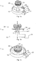
- the Figures 1a to 1c show a first variant of an assembly according to the invention in different views.
- the assembly 1 is shown in a disassembled or exploded view, in which the electronic subassembly 30 with the four contact elements 22 attached to it has not yet been displaced along the guide element 11 into the housing 10.
- the electronic subassembly 30 has a tubular counter-element 31 with which it can be arranged around the pin-shaped or cylindrical guide element 11 and is displaceable on the guide element 11 along the assembly direction X into the housing 10.
- the connector 20 comprises a connector housing 21 formed in one piece with the housing 10, a frame element 24 and the four contact elements 22 received in the frame element 24 and fixed with the frame element 24 on the electronic subassembly 30.
- the electronic subassembly 30 has a Printed circuit board on which the frame element 24 is attached and with the conductor tracks of which the contact elements 22 are contacted.
- the housing 10 integrally and in one piece with the connector housing 21, for example by injection molding and to be joined with the electronic subassembly 30 with a single assembly movement or with a single assembly step, the connector 20 being assembled at the same time.
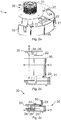
- the Figures 2a to 2c illustrate an alternative embodiment
- the Figures 2b and 2c each show a section through the assembly 1, which runs in particular through the connector 20 or its connector housing 21.
- the main difference compared to the variant from the Figures 1a to 1c is that the plug connector 20 is designed closer to the guide element 11 in the radial direction than the pin-shaped or cylindrical guide element 11, whereby the contact elements 22 do not protrude beyond the housing 10 in the plug-in direction Y. Therefore, a recess formed in the connector housing 21, which extends completely within the housing 10, is provided for a respective contact element 22.
- the frame element 24 also forms a projection 26 for each contact element 22, which extends along the respective contact element 22 through the respective recess 23 and additionally supports the respective contact element 22 in the assembly direction X, so that each contact element 22 along the assembly direction X is stabilized and supported on one side by the connector housing 21 and on the opposite side by the respective projection 26.
- the Figures 3a and 3b show a further embodiment according to the invention, in which the housing 10 is designed as an outer ring and as an inner pot connected to it in one piece via webs, the electronic subassembly 30 essentially consisting of a printed circuit board with conductor tracks formed on it, which extends along one of the webs from the inner pot to the outer ring and as a result, the connector 20 arranged on the outer ring electrically contacts the inner pot or a further electrical subassembly arranged on the inner pot.
- the connector housing 21 is in turn formed in one piece with the housing 10, with not only the contact elements 22 extending beyond the housing 10, but the entire connector 20 being arranged outside the housing 10.
- the section of the electronic subassembly 30 extends out of the housing 10 into the plug connector 20.
Landscapes
- Engineering & Computer Science (AREA)
- Power Engineering (AREA)
- Mechanical Engineering (AREA)
- General Engineering & Computer Science (AREA)
- Microelectronics & Electronic Packaging (AREA)
- Connector Housings Or Holding Contact Members (AREA)
- Details Of Connecting Devices For Male And Female Coupling (AREA)
Abstract
Description
- Die Erfindung betrifft eine Baugruppe mit einem Gehäuse, einem mehrteiligen Steckverbinder und einer elektronischen Unterbaugruppe, wobei die Steckrichtung des Steckverbinders orthogonal zu einer Montagerichtung der Baugruppe ist und der mehrteilige Steckverbinder bei einer Montage der Unterbaugruppe in das Gehäuse entlang der Montagerichtung fügbar ist.
- Aus dem Stand der Technik ist eine Vielzahl von Baugruppen mit Gehäusen, elektronischen Unterbaugruppen und Steckverbindern bekannt, bei welchen jedoch die Steckverbinder meist aufwändig mit den elektronischen Unterbaugruppen kontaktiert werden müssen, nachdem die elektronischen Unterbaugruppen in das zugehörige Gehäuse montiert wurden. Meist ist hierfür vorgesehen, zunächst die elektronische Unterbaugruppe in dem Gehäuse zu montieren, anschließend den Steckverbinder an dem Gehäuse zu fixieren und mit der elektronischen Unterbaugruppe elektrisch zu kontaktieren. Dies führt jedoch zum einen zu zusätzlichem Montageaufwand und zum anderen zu erhöhten Platzbedarf, da die Baugruppe auf eine bessere Zugänglichkeit für die Montage des Steckverbinders ausgelegt sein muss.
- Alternativ ist im Stand der Technik bekannt, die Steckverbinder zunächst an der elektronischen Unterbaugruppe zu fixieren und zu kontaktieren und anschließend gemeinsam in das Gehäuse zu fügen. Hierbei ist jedoch problematisch, dass der Steckverbinder vorzugsweise zusätzlich mit dem Gehäuse verbunden werden muss, um eine hohe mechanische Belastbarkeit des Steckverbinder gewährleisten zu können und um die elektronische Unterbaugruppe von mechanischen Kräften frei zu halten. Dadurch ergibt sich ebenfalls ein vergleichsweise hoher Montageaufwand für die gesamte Baugruppe.
- Ist der Steckverbinder ganz oder teilweise bereits an der elektronischen Unterbaugruppe fixiert und soll sich der Steckverbinder aus dem Gehäuse heraus erstrecken bzw. von außerhalb des Gehäuses zugänglich sein, ist zudem problematisch, dass zumeist die Montagerichtung der elektronischen Unterbaugruppe in das Gehäuse und die Steckrichtung des Steckverbinders parallel sein müssen.
- Der Erfindung liegt deshalb die Aufgabe zugrunde, die vorgenannten Nachteile zu überwinden und eine Baugruppe mit einem Gehäuse, einem Steckverbinder und einer elektronischen Unterbaugruppe bereitzustellen, deren Steckverbinder sich zugleich bei der Montage der elektronischen Unterbaugruppe in dem Gehäuse und mit geringem Montageaufwand montieren lässt.
- Diese Aufgabe wird durch die Merkmalskombination gemäß Patentanspruch 1 gelöst.
- Erfindungsgemäß wird eine Baugruppe umfassend ein Gehäuse, einen Steckverbinder und eine elektronische Unterbaugruppe vorgeschlagen. Das Gehäuse weist zur leichteren Montage und Festlegung der Position der elektronischen Unterbaugruppe in dem Gehäuse ein Führungselement und die elektronische Unterbaugruppe ein dazu korrespondierende Gegenelement auf, wobei das Führungselement und das Gegenelement eine Montagerichtung bestimmen, entlang welcher die elektronische Unterbaugruppe in das Gehäuse verschiebbar ist. Folglich kann die elektronische Unterbaugruppe durch eine Verschiebung entlang der Montagerichtung in dem Gehäuse angeordnet werden, wobei die Unterbaugruppe dazu vorzugsweise bis auf eine beispielsweise durch einen Anschlag bestimmte Montageposition verschoben wird. Ferner ist erfindungsgemäß vorgesehen, dass der Steckverbinder ein an dem Gehäuse angeordnetes und vorzugsweise an diesem befestigtes Steckverbindergehäuse und zumindest ein an der elektronischen Unterbaugruppe angeordnetes Kontaktelement aufweist. Das zumindest eine an der elektronischen Unterbaugruppe angeordnete Kontaktelement erstreckt sich orthogonal zu der, Montagerichtung und bestimmt dadurch vorzugsweise zugleich die Steckrichtung des Steckverbinders, welche entsprechend orthogonal zu der Montagerichtung ist. Um ein Fügen des zumindest einen Kontaktelements des Steckverbinders in das Steckverbindergehäuse zu ermöglichen, ist ferner vorgesehen, dass das Steckverbindergehäuse und/oder das Gehäuse für jeweils ein an der elektronischen Unterbaugruppe angeordnetes Kontaktelement also für jedes an der elektronischen Unterbaugruppe angeordnete Kontaktelement jeweils eine zumindest in die Montagerichtung offene Ausnehmung aufweist, durch welche hindurch das jeweilige Kontaktelement bei einer Verschiebung der elektronischen Unterbaugruppe entlang der Montagerichtung in eine in dem Steckverbindergehäuse liegende Endposition des zumindest einen Kontaktelements verschiebbar ist.
- Vorzugsweise wird die Endposition der Kontaktelemente bzw. des zumindest einen Kontaktelements in dem Steckverbindergehäuse dadurch bestimmt, dass die Kontaktelemente / das Kontaktelement vollständig in dem Steckverbindergehäuse oder einem in dem Steckverbindergehäuse bestimmten Aufnahmeraum angeordnet sind / ist und sich zugleich in der vorbestimmten Endposition befinden / befindet, in welcher ein zu dem Steckverbinder korrespondierendes Gegensteckelement entlang einer Steckrichtung in den Steckverbinder einsteckbar ist. Befindet sich das Kontaktelement bzw. die Kontaktelemente in ihrer Endposition ist vorzugsweise zugleich die elektronische Unterbaugruppe in ihrer Montageposition bzw. in ihrer Endposition in dem Gehäuse angeordnet.
- In einer vorteilhaften Weiterbildung ist vorgesehen, dass die Baugruppe eine Ventilatorbaugruppe ist, die elektronische Unterbaugruppe einen Stator eines Elektromotors aufweist oder zumindest elektrisch kontaktiert und zumindest das Gehäuse die elektronische Unterbaugruppe und/oder den Elektromotor topfförmig umgibt. Insbesondere kann das Gehäuse hierbei ausgebildet sein, neben dem Stator zumindest einen Teil des Rotors aufzunehmen.
- Um eine mechanische Stabilität des Steckverbinders zu erhöhen und um zugleich zu gewährleisten, dass mehrere nebeneinander angeordnete Kontaktelemente voneinander isoliert sind und bleiben, ist bei einer ebenfalls vorteilhaften Ausgestaltung der Baugruppe vorgesehen, dass der Steckverbinder zumindest zwei an der elektronischen Unterbaugruppe angeordnete Kontaktelemente aufweist, wobei zwischen den jeweiligen Ausnehmungen für jeweils ein Kontaktelement jeweils ein Steg ausgebildet ist, der die Ausnehmungen trennt. Der jeweilige Steg ist abhängig davon, ob das Steckverbindergehäuse und/oder das Gehäuse die Ausnehmung aufweist, vorzugsweise durch das entsprechende Gehäuse oder beide Gehäuse ausgebildet. Durch die Ausnehmungen und die dazwischen angeordneten Stege sind die Ausnehmungen als sich vorzugsweise in Steckrichtung des Steckverbinders und zugleich in Montagerichtung durch das Steckverbindergehäuse erstreckende Spalten ausgebildet, wobei jeweils zwei Spalten durch einen dazwischen liegenden Steg voneinander getrennt sind, welcher sich wie die Ausnehmungen orthogonal zu der Montagerichtung erstreckt.
- Bei einer Variante, welche die Stabilität des Steckverbinders erhöht und daher vorteilhaft ist, bildet das Steckverbindergehäuse einen bereits zuvor erwähnten Aufnahmeraum aus, in welchem das zumindest eine Kontaktelement in seiner Endposition angeordnet ist und welcher in eine Steckrichtung des Steckverbinders sowie durch die zumindest eine Ausnehmung offen ist. Der Aufnahmeraum ist zudem abschnittsweise in Umfangsrichtung um die Steckrichtung und vorzugsweise angrenzend zu der Öffnung in Steckrichtung vollständig geschlossen, so dass sich die Ausnehmungen nicht bis zu der Öffnung in Steckrichtung erstrecken. Die Öffnung in Steckrichtung liegt vorzugsweise auf einer von der elektronischen Unterbaugruppe weg weisenden Seite des Steckverbinders bzw. des Steckverbindergehäuses.
- Das zumindest eine Kontaktelement ist vorzugsweise ein gewinkelter oder gerader Lötstift, welcher auch als Pin bezeichnet werden kann, wobei sicher der Lötstift zumindest abschnittsweise orthogonal zu der Montagerichtung erstreckt. Durch die Erstreckung des Lötstifts bzw. der Lötstifte orthogonal zu der Montagerichtung wird entsprechend zugleich die Steckrichtung des Steckverbinders bestimmt. Ist eine Vielzahl von Kontaktelementen vorgesehen, sind diese vorzugsweise als Stiftleiste bzw. als Platinensteckverbinder ausgebildet.
- Vorzugsweise umfasst die elektronische Unterbaugruppe eine Leiterplatte mit Leiterbahnen, wobei das zumindest eine Kontaktelement mit einer Leiterbahn der Leiterplatte kontaktiert ist. Sind mehrere Kontaktelemente vorgesehen, sind diese vorzugsweise jeweils mit einer Leiterbahn kontaktiert, durch welche das jeweilige Kontaktelement mit weiteren elektronischen Bauteilen der elektronischen Unterbaugruppe und beispielsweise einem Stator elektrisch verbunden sind.
- An der Leiterplatte sind zudem bei einer weiteren Variante Befestigungselemente vorgesehen, durch welche die elektronische Unterbaugruppe an dem Gehäuse fixierbar ist. Die Befestigungselemente können beispielsweise als Rasthaken oder Schrauben ausgebildet sein, welche in dafür jeweils vorgesehene und von dem Gehäuse bereitgestellte Gegenelemente eingreifen. Durch die Befestigungselemente an der elektronischen Unterbaugruppe ist zudem zugleich das zumindest eine Kontaktelement in seiner Endposition fixierbar, so dass die Befestigungselemente der elektronischen Unterbaugruppe zugleich die Kontaktelemente an dem Steckverbindergehäuse fixieren.
- Vorteilhaft ist insbesondere eine Weiterbildung, bei welcher das Steckverbindergehäuse einstückig und zumindest abschnittsweise integral mit Gehäuse ausgebildet ist. Entsprechend kann das Steckverbindergehäuse und das Gehäuse einstückig gefertigt werden, wobei ebenfalls einstückig oder separat ein zusätzlicher Einsatz vorgesehen sein kann, welcher die Ausnehmungen bzw. die Stege ausbildet.
- Um die Kontaktelemente an der elektronischen Unterbaugruppe zu stabilisieren und in einer vorbestimmten Position zueinander und/oder an der Unterbaugruppe zu halten, ist bei einer vorteilhaften Ausgestaltung der Erfindung ferner vorgesehen, dass der Steckverbinder ein Rahmenelement aufweist, in welchem das zumindest eine Kontaktelement aufgenommen ist und mit welchem das zumindest eine Kontaktelement an der elektronischen Unterbaugruppe und insbesondere an einer Leiterplatte der elektronischen Unterbaugruppe fixiert ist. Darüber hinaus liegt das Rahmenelement mit dem zumindest einen Kontaktelement in der Endposition an der jeweiligen Ausnehmung an und/oder erstreckt sich zumindest abschnittsweise, beispielsweise mit einem dafür ausgebildeten Vorsprung, in die Ausnehmung hinein.
- Bei einer Variante, bei welcher sich das Rahmenelement insbesondere durch einen Vorsprung in die Ausnehmung hinein erstreckt, kann zum einen vorgesehen sein, dass das jeweilige Kontaktelement in seiner zugehörigen Ausnehmung durch den Vorsprung stabilisiert wird oder, dass der Vorsprung die Ausnehmung abschnittsweise verschließt, wodurch das Rahmenelement integral einen Deckel bildet, welcher die Ausnehmung bzw. die Ausnehmungen zumindest abschnittsweise abdeckt, so dass der Aufnahmeraum des Steckverbinders bzw. der Steckverbinder an sich von einem Innenraum des Gehäuses, in welchem die elektronische Unterbaugruppe aufgenommen ist, getrennt und vorzugsweise abgedichtet ist. Insbesondere kann hierdurch ein Deckel zur Abdeckung der Ausnehmung(en) in Steckrichtung bereitgestellt werden, wobei vorzugweise jede der Ausnehmungen durch den so gebildeten Deckel abgedeckt ist. Beispielsweise kann das Rahmenelement für jede Ausnehmung jeweils einen Vorsprung bilden, welcher sich jeweils in die zugehörige Ausnehmung hinein erstreckt und die Ausnehmung dadurch vollständig oder zumindest in Steckrichtung zu der elektronischen Unterbaugruppe hin verschließt. Alternativ kann das Rahmenelement auch mit einer ebenen Fläche die Ausnehmung oder die Ausnehmungen überlagern und unmittelbar an dem die Ausnehmungen bildenden Gehäuse anliegen und diese dadurch vollständig oder zumindest in Steckrichtung zu der elektronischen Unterbaugruppe hin verschließen. Vorteilhaft ist zudem, wenn der dadurch gebildete Deckel die Ausnehmung dicht und insbesondere Wasserdicht verschließt wobei hierfür an dem Deckel auch Dichtelemente vorgesehen sein können. Durch einen solchen Deckel, kann der Innenraum des Gehäuses oder zumindest ein Abschnitt des Innenraums des Gehäuses gegenüber der Umgebung und gegenüber dem Aufnahmeraum des Steckverbinders abgedichtet werden.
- Ist ein Rahmenelement mit einem Vorsprung vorhanden, kann zudem vorgesehen sein, dass hierdurch eine Position der elektronischen Unterbaugruppe in Umfangsrichtung um die Montagerichtung festgelegt wird und die Ausrichtung der Unterbaugruppe gegenüber dem Gehäuse festgelegt ist. Hierzu ist bei dieser Variante vorgesehen, dass das Rahmenelement zumindest einen Vorsprung ausbildet, der sich in der Endposition des Kontaktelements in eine Ausnehmung erstreckt. Durch den Vorsprung und die Ausnehmung, in welche sich der Vorsprung hinein erstreckt ist eine Ausrichtung bzw. eine Verdrehung der elektronischen Unterbaugruppe gegenüber dem Gehäuse in Umfangsrichtung um die Montagerichtung bestimmt.
- Alternativ hierzu kann auch vorgesehen sein, dass das Führungselement und das Gegenelement die Ausrichtung bzw. die Verdrehung der elektronischen Unterbaugruppe gegenüber dem Gehäuse in Umfangsrichtung um die Montagerichtung bestimmen. Hierfür können das Führungselement und das Gegenelement beispielsweise bezüglich ihrer Querschnittsformen jeweils eine zueinander korrespondierende Asymmetrie bzw. einen Vorsprung und eine dazu korrespondierende Nut aufweisen, so dass die elektronische Unterbaugruppe nur in einer bestimmten Orientierung entlang der Montagerichtung verschiebbar ist.
- Darüber hinaus ist eine Weiterbildung von Vorteil, bei welcher der Steckverbinder radial zu der Montagerichtung und/oder in Montagerichtung über das Gehäuse hinausragt.
- Ebenfalls vorteilhaft ist zudem eine Ausbildung der Baugruppe, bei welcher das zumindest eine Kontaktelement zumindest in seiner Endposition aus dem Gehäuse hinaus ragt.
- Von dem erfindungsgemäßen Grundgedanken ist darüber hinaus nicht nur eine Ausbildungsform umfasst, bei welcher alle Kontaktelemente an der elektronischen Unterbaugruppe angeordnet sind, sondern beispielsweise auch eine Variante, bei welcher nur ein Teil der Kontaktelemente des Steckverbinders an der elektronischen Unterbaugruppe angeordnet sind.
- Die vorstehend offenbarten Merkmale sind beliebig kombinierbar, soweit dies technisch möglich ist und diese nicht im Widerspruch zueinander stehen.
- Andere vorteilhafte Weiterbildungen der Erfindung sind in den Unteransprüchen gekennzeichnet bzw. werden nachstehend zusammen mit der Beschreibung der bevorzugten Ausführung der Erfindung anhand der Figuren näher dargestellt. Es zeigen:
- Fig. 1a - 1c
- jeweils eine Ansicht einer ersten Variante einer erfindungsgemäßen Baugruppe;
- Fig. 2a - 2c
- jeweils eine Ansicht einer zweiten Variante einer erfindungsgemäßen Baugruppe;
- Fig. 3a - 3b
- jeweils eine Ansicht einer dritten Variante einer erfindungsgemäßen Baugruppe
- Die Figuren sind beispielhaft schematisch. Gleiche Bezugszeichen in den Figuren weisen auf gleiche funktionale und/oder strukturelle Merkmale hin.
- Die
Figuren 1a bis 1c zeigen eine erste Variante einer erfindungsgemäßen Baugruppe in verschiedenen Ansichten. InFigur 1a und Figur 1b ist die Baugruppe 1 in einer demontierten bzw. explosionsartigen Ansicht dargestellt, bei welcher die elektronische Unterbaugruppe 30 mit den daran befestigten vier Kontaktelementen 22 noch nicht entlang dem Führungselement 11 in das Gehäuse 10 verschoben ist. Hierfür weist die elektronische Unterbaugruppe 30 ein rohrförmig ausgebildetes Gegenelement 31 auf, mit welchem es um das zapfen- bzw. zylinderförmig ausgebildete Führungselement 11 anordenbar und an dem Führungselement 11 entlang der Montagerichtung X in das Gehäuse 10 hinein verschiebbar ist. - Der Steckverbinder 20 umfasst ein einstückig mit dem Gehäuse 10 ausgebildetes Steckverbindergehäuse 21, ein Rahmenelement 24 sowie die vier in dem Rahmenelement 24 aufgenommenen und mit dem Rahmenelement 24 an der elektronischen Unterbaugruppe 30 fixierten Kontaktelemente 22. Neben einem Stator eines Elektromotors weist die elektronische Unterbaugruppe 30 eine Leiterplatte auf, an welcher das Rahmenelement 24 befestigt ist und mit dessen Leiterbahnen die Kontaktelemente 22 kontaktiert sind.
- Wie insbesondere in
Figur 1b gut zu erkennen, erstrecken sich die Kontaktelemente 22 in Steckrichtung Y bzw. orthogonal zu der Montagerichtung X aus dem Gehäuse 10 heraus. - Um bei der Montage bzw. der Verschiebung der elektronischen Unterbaugruppe 30 in das Gehäuse 10 zugleich auch den mehrteiligen Steckverbinder 20 montieren zu können, ohne hierfür zusätzliche Montageschritte vorsehen zu müssen, ist bei der dargestellten Variante vorgesehen, dass für jedes Kontaktelement 22 jeweils sowohl in dem Gehäuse 10 eine Ausnehmung 12 als auch in dem Steckverbindergehäuse 21 eine Ausnehmung 23 bzw. eine Ausnehmung mit einem ersten Abschnitt 12 und einem zweiten Abschnitt 23 vorgesehen ist. Entsprechend können die Kontaktelemente 22 bei einer Verschiebung der elektronischen Unterbaugruppe 30 entlang der Montagerichtung X durch die Ausnehmungen 12, 23 hindurch in den durch das Steckverbindergehäuse 21 gebildeten Aufnahmeraum verschoben werden, in welchem sie in der Endposition, wie sie in
Figur 1c gezeigt ist, vollständig aufgenommen sind. - Daher ist es möglich, das Gehäuse 10 integral und einstückig mit dem Steckverbindergehäuse 21 beispielsweise im Spritzgussverfahren herzustellen und mit einer einzigen Montagebewegung bzw. mit einem einzigen Montageschritt mit der elektronischen Unterbaugruppe 30 zu Fügen, wobei dabei zugleich der Steckverbinder 20 montiert wird.
- Die
Figuren 2a bis 2c illustrieren eine alternative Ausführungsvariante, wobei dieFiguren 2b und 2c jeweils einen Schnitt durch die Baugruppe 1 zeigen, welcher insbesondere durch den Steckverbinder 20 bzw. dessen Steckverbindergehäuse 21 verläuft. Der wesentliche Unterschied gegenüber der Variante aus denFiguren 1a bis 1c ist, dass der Steckverbinder 20 in Radialrichtung gegenüber dem zapfen- bzw. zylinderförmig ausgebildeten Führungselement 11 näher an dem Führungselement 11 ausgebildet ist, wodurch die Kontaktelemente 22 in Steckrichtung Y nicht über das Gehäuse 10 herausragen. Daher ist für ein jeweiliges Kontaktelement 22 jeweils eine in dem Steckverbindergehäuse 21 ausgebildete Ausnehmung vorgesehen, welche sich vollständig innerhalb des Gehäuses 10 erstreckt. - In dem in
Figur 2c gezeigten Schnitt sind die Kontaktelemente 22 ihrer Endposition gezeigt, wobei die elektronische Unterbaugruppe 30 dabei ebenfalls in ihrer End- bzw. Montageposition ist. In dem Schnitt ist zudem der Aufnahmeraum 25 des Steckverbinders 20 erkennbar, in welchen hinein sich die Kontaktelemente 22 erstrecken. - Bei der Variante, wie sie in den
Figuren 2a bis 2c dargestellt ist, bildet das Rahmenelement 24 zudem für jedes Kontaktelement 22 einen Vorsprung 26 aus, welcher sich entlang dem jeweiligen Kontaktelement 22 durch die jeweilige Ausnehmung 23 erstreckt und das jeweilige Kontaktelement 22 in die Montagerichtung X zusätzlich stützt, so dass jedes Kontaktelement 22 entlang der Montagerichtung X zu einer Seite hin durch das Steckverbindergehäuse 21 und zu der gegenüberliegenden Seite durch den jeweiligen Vorsprung 26 stabilisiert und gestützt ist. - Die
Figuren 3a und 3b zeigen eine weitere erfindungsgemäße Ausbildung, bei welcher das Gehäuse 10 als ein Außenring und als ein damit einstückig über Stege verbundener Innentopf ausgebildet ist, wobei die elektronische Unterbaugruppe 30 im Wesentlichen aus einer Leiterplatte mit daran ausgebildeten Leiterbahnen besteht, welche sich entlang einem der Stege von dem Innentopf zu dem Außenring erstreckt und dadurch den an dem Außenring angeordneten Steckverbinder 20 elektrisch mit dem Innentopf bzw. einer an dem Innentopf angeordneten weiteren elektrischen Unterbaugruppe kontaktiert. - Das Steckverbindergehäuse 21 ist wiederum einstückig mit dem Gehäuse 10 ausgebildet, wobei sich nicht nur die Kontaktelemente 22 über das Gehäuse 10 hinaus erstrecken, sondern der gesamte Steckverbinder 20 außerhalb des Gehäuses 10 angeordnet ist. Hierfür erstreckt sich in Abschnitt der elektronischen Unterbaugruppe 30 aus dem Gehäuse 10 heraus in den Steckverbinder 20 hinein.
Claims (12)
- Baugruppe (1) umfassend ein Gehäuse (10), einen Steckverbinder (20) und eine elektronische Unterbaugruppe (30),wobei das Gehäuse (10) ein Führungselement (11) und die elektronische Unterbaugruppe (30) ein dazu korrespondierende Gegenelement (31) aufweistund wobei das Führungselement (11) und das Gegenelement (31) eine Montagerichtung (X) bestimmen, entlang welcher die elektronische Unterbaugruppe (30) in das Gehäuse (10) verschiebbar ist,wobei der Steckverbinder (20) ein an dem Gehäuse (10) angeordnetes Steckverbindergehäuse (21) und zumindest ein an der elektronischen Unterbaugruppe (30) angeordnetes Kontaktelement (22) aufweist,wobei sich das zumindest eine an der elektronischen Unterbaugruppe (30) angeordnete Kontaktelement (22) orthogonal zu der Montagerichtung (X) erstreckt unddas Steckverbindergehäuse (21) und/oder das Gehäuse (10) für jeweils ein an der elektronischen Unterbaugruppe (30) angeordnetes Kontaktelement (22) eine zumindest in die Montagerichtung (X) offene Ausnehmung (12, 23) aufweist, durch welche hindurch das jeweilige Kontaktelement (22) bei einer Verschiebung der elektronischen Unterbaugruppe (30) entlang der Montagerichtung (X) in eine in dem Steckverbindergehäuse (21) liegende Endposition verschiebbar ist.
- Baugruppe nach Anspruch 1,
wobei die Baugruppe (1) eine Ventilatorbaugruppe ist, die elektronische Unterbaugruppe (30) einen Stator eines Elektromotors aufweist oder zumindest elektrisch kontaktiert und das Gehäuse (10) zumindest die elektronische Unterbaugruppe (30) und/oder den Elektromotor topfförmig umgibt. - Baugruppe nach Anspruch 1 oder 2,
wobei der Steckverbinder (20) zumindest zwei an der elektronischen Unterbaugruppe (30) angeordnete Kontaktelemente (22) aufweist und wobei zwischen den jeweiligen Ausnehmungen (12, 23) für jeweils ein Kontaktelement (22) jeweils ein Steg ausgebildet ist, der die Ausnehmungen (12, 23) trennt. - Baugruppe nach einem der vorhergehenden Ansprüche,wobei das Steckverbindergehäuse (21) einen Aufnahmeraum ausbildet, in welchem das zumindest eine Kontaktelement (22) in seiner Endposition angeordnet ist und welcher in eine Steckrichtung (Y) des Steckverbinders (20) sowie durch die zumindest eine Ausnehmung (12, 23) offen ist,und wobei der Aufnahmeraum abschnittsweise in Umfangsrichtung um die Steckrichtung (Y) vollständig geschlossen ist.
- Baugruppe nach einem der vorhergehenden Ansprüche,
wobei das zumindest eine Kontaktelement (22) ein gewinkelter oder gerader Lötstift ist, welcher sich zumindest abschnittsweise orthogonal zu der Montagerichtung (X) erstreckt. - Baugruppe nach einem der vorhergehenden Ansprüche,
wobei die elektronische Unterbaugruppe (30) eine Leiterplatte mit Leiterbahnen umfasst und das zumindest eine Kontaktelement (22) mit einer Leiterbahn der Leiterplatte kontaktiert ist. - Baugruppe nach dem vorhergehenden Anspruch,
wobei an der Leiterplatte Befestigungselemente vorgesehen sind, durch welche die elektronische Unterbaugruppe (30) an dem Gehäuse (10) fixierbar ist. - Baugruppe nach einem der vorhergehenden Ansprüche,
wobei das Steckverbindergehäuse (21) einstückig und zumindest abschnittsweise integral mit Gehäuse (10) ausgebildet ist. - Baugruppe nach einem der vorhergehenden Ansprüche,wobei der Steckverbinder (20) ein Rahmenelement (24) aufweist, in welchem das zumindest eine Kontaktelement aufgenommen ist und mit welchem das zumindest eine Kontaktelement (22) an der elektronischen Unterbaugruppe (30) fixiert ist,wobei das Rahmenelement (24) mit dem zumindest einen Kontaktelement (22) in der Endposition an der jeweiligen Ausnehmung (12, 23) anliegt und/oder sich zumindest abschnittsweise in diese hinein erstreckt.
- Baugruppe nach dem vorhergehenden Anspruch,wobei das Rahmenelement (24) zumindest einen Vorsprung ausbildet, der sich in der Endposition des Kontaktelements (22) in eine Ausnehmung (12, 23) erstreckt,und wobei durch den Vorsprung und die Ausnehmung (12, 23), in welche sich der Vorsprung hinein erstreckt, eine Ausrichtung der elektronischen Unterbaugruppe (30) gegenüber dem Gehäuse (10) in Umfangsrichtung um die Montagerichtung (X) bestimmt ist.
- Baugruppe nach einem der vorhergehenden Ansprüche 1 bis 9,
wobei das Führungselement (11) und das Gegenelement (31) eine Ausrichtung der elektronischen Unterbaugruppe (30) gegenüber dem Gehäuse (10) in Umfangsrichtung um die Montagerichtung (X) bestimmen. - Baugruppe nach einem der vorhergehenden Ansprüche,
wobei das zumindest eine Kontaktelement (22) zumindest in seiner Endposition aus dem Gehäuse (10) hinaus ragt.
Applications Claiming Priority (1)
| Application Number | Priority Date | Filing Date | Title |
|---|---|---|---|
| DE102020100988.7A DE102020100988A1 (de) | 2020-01-16 | 2020-01-16 | Baugruppe mit orthogonal zur Montagerichtung der Baugruppe montierbaren Steckverbinder |
Publications (1)
| Publication Number | Publication Date |
|---|---|
| EP3852239A1 true EP3852239A1 (de) | 2021-07-21 |
Family
ID=74130104
Family Applications (1)
| Application Number | Title | Priority Date | Filing Date |
|---|---|---|---|
| EP21150918.7A Withdrawn EP3852239A1 (de) | 2020-01-16 | 2021-01-11 | Baugruppe mit orthogonal zur montagerichtung der baugruppe montierbaren steckerverbinder |
Country Status (4)
| Country | Link |
|---|---|
| US (1) | US20210226508A1 (de) |
| EP (1) | EP3852239A1 (de) |
| CN (1) | CN113141085B (de) |
| DE (1) | DE102020100988A1 (de) |
Cited By (1)
| Publication number | Priority date | Publication date | Assignee | Title |
|---|---|---|---|---|
| US20220345002A1 (en) * | 2019-06-20 | 2022-10-27 | Panasonic Intellectual Property Management Co., Ltd. | Motor unit and moving body |
Citations (6)
| Publication number | Priority date | Publication date | Assignee | Title |
|---|---|---|---|---|
| JP2010130833A (ja) * | 2008-11-28 | 2010-06-10 | Mitsubishi Electric Corp | 電動機の固定子及び電動機及び空気調和機及び電動機の製造方法 |
| KR101573970B1 (ko) * | 2012-09-17 | 2015-12-02 | 한온시스템 주식회사 | 전동 압축기 |
| JP2016207963A (ja) * | 2015-04-28 | 2016-12-08 | 株式会社デンソー | 電子制御装置および駆動装置 |
| US9768542B2 (en) * | 2014-12-31 | 2017-09-19 | Borgwarner Inc. | Blind electrical connector to printed circuit board in housing |
| US20180080573A1 (en) * | 2016-09-20 | 2018-03-22 | Johnson Electric S.A. | Actuator |
| DE202019102972U1 (de) * | 2019-05-27 | 2019-06-13 | Ebm-Papst St. Georgen Gmbh & Co. Kg | Ventilatorbaugruppe mit variabel einstellbarem Steckverbinderabgang |
Family Cites Families (12)
| Publication number | Priority date | Publication date | Assignee | Title |
|---|---|---|---|---|
| US5616975A (en) * | 1994-05-11 | 1997-04-01 | Emerson Electric Co. | Integral connector and motor housing |
| JPH10225048A (ja) * | 1997-01-31 | 1998-08-21 | Mabuchi Motor Co Ltd | 減速機付き小型モータ |
| DE10063619B4 (de) * | 2000-12-20 | 2010-02-18 | Trw Automotive Electronics & Components Gmbh & Co. Kg | Antriebseinheit für Gebläse in Fahrzeugen |
| JP2003111345A (ja) * | 2001-09-28 | 2003-04-11 | Fujitsu General Ltd | 電動機 |
| JP2003116247A (ja) * | 2001-10-04 | 2003-04-18 | Mabuchi Motor Co Ltd | 小型モータ及びその製造方法 |
| ITPD20030013A1 (it) * | 2003-01-24 | 2004-07-25 | Inarca Spa | Gruppo di connessione, particolarmente per gli |
| JP2014039421A (ja) * | 2012-08-20 | 2014-02-27 | Mitsubishi Electric Corp | モールド電動機及び空気調和機 |
| DE102013207578A1 (de) * | 2013-04-25 | 2014-10-30 | Robert Bosch Gmbh | Stellantriebsanordnung mit einem Steckverbinder sowie Steckeranordnung für eine Stellantriebsanordnung und Herstellungsverfahren einer solchen |
| CN206908442U (zh) * | 2017-07-05 | 2018-01-19 | 合肥惠利普电机有限公司 | 一种具有电路板无引线的电机接线盒及其电机 |
| JP2019187092A (ja) * | 2018-04-10 | 2019-10-24 | 日本電産サンキョー株式会社 | モータユニット |
| CN209200828U (zh) * | 2019-01-24 | 2019-08-02 | 佛山市威灵洗涤电机制造有限公司 | 电机和具有其的家用电器 |
| US11990820B2 (en) * | 2019-06-20 | 2024-05-21 | Panasonic Intellectual Property Management Co., Ltd. | Motor unit and moving body |
-
2020
- 2020-01-16 DE DE102020100988.7A patent/DE102020100988A1/de active Pending
-
2021
- 2021-01-11 EP EP21150918.7A patent/EP3852239A1/de not_active Withdrawn
- 2021-01-13 US US17/147,510 patent/US20210226508A1/en not_active Abandoned
- 2021-01-13 CN CN202110040249.5A patent/CN113141085B/zh active Active
Patent Citations (6)
| Publication number | Priority date | Publication date | Assignee | Title |
|---|---|---|---|---|
| JP2010130833A (ja) * | 2008-11-28 | 2010-06-10 | Mitsubishi Electric Corp | 電動機の固定子及び電動機及び空気調和機及び電動機の製造方法 |
| KR101573970B1 (ko) * | 2012-09-17 | 2015-12-02 | 한온시스템 주식회사 | 전동 압축기 |
| US9768542B2 (en) * | 2014-12-31 | 2017-09-19 | Borgwarner Inc. | Blind electrical connector to printed circuit board in housing |
| JP2016207963A (ja) * | 2015-04-28 | 2016-12-08 | 株式会社デンソー | 電子制御装置および駆動装置 |
| US20180080573A1 (en) * | 2016-09-20 | 2018-03-22 | Johnson Electric S.A. | Actuator |
| DE202019102972U1 (de) * | 2019-05-27 | 2019-06-13 | Ebm-Papst St. Georgen Gmbh & Co. Kg | Ventilatorbaugruppe mit variabel einstellbarem Steckverbinderabgang |
Cited By (2)
| Publication number | Priority date | Publication date | Assignee | Title |
|---|---|---|---|---|
| US20220345002A1 (en) * | 2019-06-20 | 2022-10-27 | Panasonic Intellectual Property Management Co., Ltd. | Motor unit and moving body |
| US11990820B2 (en) * | 2019-06-20 | 2024-05-21 | Panasonic Intellectual Property Management Co., Ltd. | Motor unit and moving body |
Also Published As
| Publication number | Publication date |
|---|---|
| CN113141085A (zh) | 2021-07-20 |
| DE102020100988A1 (de) | 2021-07-22 |
| CN113141085B (zh) | 2024-04-02 |
| US20210226508A1 (en) | 2021-07-22 |
Similar Documents
| Publication | Publication Date | Title |
|---|---|---|
| EP1814202B1 (de) | Kupplung | |
| DE19813458B4 (de) | Elektrischer Verbinder | |
| DE69126105T2 (de) | Ein Modul-Koaxialsteckverbinder | |
| EP0754357B1 (de) | Verbindungssystem für elektrische leiter | |
| DE102005040952A1 (de) | Elektrischer Nullkraftsteckverbinder | |
| DE102020211730B3 (de) | Gehäuse für eine auf einer Leiterplatte angeordneten elektronische Schaltung | |
| DE102013207578A1 (de) | Stellantriebsanordnung mit einem Steckverbinder sowie Steckeranordnung für eine Stellantriebsanordnung und Herstellungsverfahren einer solchen | |
| EP4135168A1 (de) | Elektrische schnittstelleneinrichtung für einen elektromotor | |
| DE102008045839B4 (de) | Anschlussdose | |
| DE10140153A1 (de) | Steckverbindung zum gleichzeitigen Verbinden mehrerer Koaxialkabel | |
| DE69205869T2 (de) | Elektrischer Erdungssteckverbinder. | |
| DE102020100988A1 (de) | Baugruppe mit orthogonal zur Montagerichtung der Baugruppe montierbaren Steckverbinder | |
| DE102024125089A1 (de) | Steckereinsatz | |
| DE102012102849A1 (de) | Befestigung und Abdichtung eines Steckanschlussmoduls in einer Gehäusewandung | |
| DE602004008094T2 (de) | Elektrischer verbinder für einen flexiblen flachleiter und schalteinrichtung | |
| DE19948037B4 (de) | Elektrisches Steckverbindungselement und -system | |
| EP2648285B1 (de) | Steckverbinder zur Montage in eine Gehäuseöffnung eines Gehäuses | |
| EP0568899A2 (de) | Mehrpoliger Kabelsteckverbinder | |
| DE10159754B4 (de) | Verbinder und Verfahren zum Verbinden eines Drahtes | |
| EP4231463B1 (de) | Steckverbinder zur montage auf einer leiterplatte | |
| EP4213314B1 (de) | Verbindungselement und elektronisches bauteil mit mehrfachem steckplatz für zweidrahttechnologie | |
| DE9205977U1 (de) | Mehrpoliger Kabelsteckverbinder | |
| EP3805639B1 (de) | Leuchte mit steckkontakt, verwendung einer solchen leuchte und steckverbinder für eine solche leuchte | |
| EP4604333A1 (de) | Hermaphroditisches isoliergehäuse für einen steckverbinder, steckverbindersystem und verfahren | |
| DE102023212867A1 (de) | Motor, insbesondere Pumpenmotor und Verfahren zu dessen Herstellung |
Legal Events
| Date | Code | Title | Description |
|---|---|---|---|
| PUAI | Public reference made under article 153(3) epc to a published international application that has entered the european phase |
Free format text: ORIGINAL CODE: 0009012 |
|
| STAA | Information on the status of an ep patent application or granted ep patent |
Free format text: STATUS: THE APPLICATION HAS BEEN PUBLISHED |
|
| AK | Designated contracting states |
Kind code of ref document: A1 Designated state(s): AL AT BE BG CH CY CZ DE DK EE ES FI FR GB GR HR HU IE IS IT LI LT LU LV MC MK MT NL NO PL PT RO RS SE SI SK SM TR |
|
| STAA | Information on the status of an ep patent application or granted ep patent |
Free format text: STATUS: REQUEST FOR EXAMINATION WAS MADE |
|
| 17P | Request for examination filed |
Effective date: 20220120 |
|
| RBV | Designated contracting states (corrected) |
Designated state(s): AL AT BE BG CH CY CZ DE DK EE ES FI FR GB GR HR HU IE IS IT LI LT LU LV MC MK MT NL NO PL PT RO RS SE SI SK SM TR |
|
| STAA | Information on the status of an ep patent application or granted ep patent |
Free format text: STATUS: EXAMINATION IS IN PROGRESS |
|
| 17Q | First examination report despatched |
Effective date: 20240806 |
|
| STAA | Information on the status of an ep patent application or granted ep patent |
Free format text: STATUS: THE APPLICATION IS DEEMED TO BE WITHDRAWN |
|
| 18D | Application deemed to be withdrawn |
Effective date: 20250909 |