EP3852186A1 - Verfahren und vorrichtung zum verbinden von metallverbundfolien für pouchzellen mit einem vorsiegelband - Google Patents
Verfahren und vorrichtung zum verbinden von metallverbundfolien für pouchzellen mit einem vorsiegelband Download PDFInfo
- Publication number
- EP3852186A1 EP3852186A1 EP21150636.5A EP21150636A EP3852186A1 EP 3852186 A1 EP3852186 A1 EP 3852186A1 EP 21150636 A EP21150636 A EP 21150636A EP 3852186 A1 EP3852186 A1 EP 3852186A1
- Authority
- EP
- European Patent Office
- Prior art keywords
- metal composite
- composite film
- tape
- presealing
- arrester
- Prior art date
- Legal status (The legal status is an assumption and is not a legal conclusion. Google has not performed a legal analysis and makes no representation as to the accuracy of the status listed.)
- Granted
Links
Images
Classifications
-
- H—ELECTRICITY
- H01—ELECTRIC ELEMENTS
- H01M—PROCESSES OR MEANS, e.g. BATTERIES, FOR THE DIRECT CONVERSION OF CHEMICAL ENERGY INTO ELECTRICAL ENERGY
- H01M50/00—Constructional details or processes of manufacture of the non-active parts of electrochemical cells other than fuel cells, e.g. hybrid cells
- H01M50/10—Primary casings; Jackets or wrappings
- H01M50/183—Sealing members
- H01M50/186—Sealing members characterised by the disposition of the sealing members
-
- H—ELECTRICITY
- H01—ELECTRIC ELEMENTS
- H01M—PROCESSES OR MEANS, e.g. BATTERIES, FOR THE DIRECT CONVERSION OF CHEMICAL ENERGY INTO ELECTRICAL ENERGY
- H01M10/00—Secondary cells; Manufacture thereof
- H01M10/04—Construction or manufacture in general
- H01M10/0413—Large-sized flat cells or batteries for motive or stationary systems with plate-like electrodes
-
- H—ELECTRICITY
- H01—ELECTRIC ELEMENTS
- H01M—PROCESSES OR MEANS, e.g. BATTERIES, FOR THE DIRECT CONVERSION OF CHEMICAL ENERGY INTO ELECTRICAL ENERGY
- H01M50/00—Constructional details or processes of manufacture of the non-active parts of electrochemical cells other than fuel cells, e.g. hybrid cells
- H01M50/10—Primary casings; Jackets or wrappings
- H01M50/102—Primary casings; Jackets or wrappings characterised by their shape or physical structure
- H01M50/105—Pouches or flexible bags
-
- H—ELECTRICITY
- H01—ELECTRIC ELEMENTS
- H01M—PROCESSES OR MEANS, e.g. BATTERIES, FOR THE DIRECT CONVERSION OF CHEMICAL ENERGY INTO ELECTRICAL ENERGY
- H01M50/00—Constructional details or processes of manufacture of the non-active parts of electrochemical cells other than fuel cells, e.g. hybrid cells
- H01M50/10—Primary casings; Jackets or wrappings
- H01M50/116—Primary casings; Jackets or wrappings characterised by the material
- H01M50/117—Inorganic material
- H01M50/119—Metals
-
- H—ELECTRICITY
- H01—ELECTRIC ELEMENTS
- H01M—PROCESSES OR MEANS, e.g. BATTERIES, FOR THE DIRECT CONVERSION OF CHEMICAL ENERGY INTO ELECTRICAL ENERGY
- H01M50/00—Constructional details or processes of manufacture of the non-active parts of electrochemical cells other than fuel cells, e.g. hybrid cells
- H01M50/10—Primary casings; Jackets or wrappings
- H01M50/116—Primary casings; Jackets or wrappings characterised by the material
- H01M50/124—Primary casings; Jackets or wrappings characterised by the material having a layered structure
-
- H—ELECTRICITY
- H01—ELECTRIC ELEMENTS
- H01M—PROCESSES OR MEANS, e.g. BATTERIES, FOR THE DIRECT CONVERSION OF CHEMICAL ENERGY INTO ELECTRICAL ENERGY
- H01M50/00—Constructional details or processes of manufacture of the non-active parts of electrochemical cells other than fuel cells, e.g. hybrid cells
- H01M50/10—Primary casings; Jackets or wrappings
- H01M50/172—Arrangements of electric connectors penetrating the casing
- H01M50/174—Arrangements of electric connectors penetrating the casing adapted for the shape of the cells
- H01M50/178—Arrangements of electric connectors penetrating the casing adapted for the shape of the cells for pouch or flexible bag cells
-
- H—ELECTRICITY
- H01—ELECTRIC ELEMENTS
- H01M—PROCESSES OR MEANS, e.g. BATTERIES, FOR THE DIRECT CONVERSION OF CHEMICAL ENERGY INTO ELECTRICAL ENERGY
- H01M50/00—Constructional details or processes of manufacture of the non-active parts of electrochemical cells other than fuel cells, e.g. hybrid cells
- H01M50/10—Primary casings; Jackets or wrappings
- H01M50/183—Sealing members
- H01M50/184—Sealing members characterised by their shape or structure
-
- H—ELECTRICITY
- H01—ELECTRIC ELEMENTS
- H01M—PROCESSES OR MEANS, e.g. BATTERIES, FOR THE DIRECT CONVERSION OF CHEMICAL ENERGY INTO ELECTRICAL ENERGY
- H01M50/00—Constructional details or processes of manufacture of the non-active parts of electrochemical cells other than fuel cells, e.g. hybrid cells
- H01M50/50—Current conducting connections for cells or batteries
- H01M50/531—Electrode connections inside a battery casing
- H01M50/533—Electrode connections inside a battery casing characterised by the shape of the leads or tabs
-
- H—ELECTRICITY
- H01—ELECTRIC ELEMENTS
- H01M—PROCESSES OR MEANS, e.g. BATTERIES, FOR THE DIRECT CONVERSION OF CHEMICAL ENERGY INTO ELECTRICAL ENERGY
- H01M50/00—Constructional details or processes of manufacture of the non-active parts of electrochemical cells other than fuel cells, e.g. hybrid cells
- H01M50/50—Current conducting connections for cells or batteries
- H01M50/531—Electrode connections inside a battery casing
- H01M50/534—Electrode connections inside a battery casing characterised by the material of the leads or tabs
-
- H—ELECTRICITY
- H01—ELECTRIC ELEMENTS
- H01M—PROCESSES OR MEANS, e.g. BATTERIES, FOR THE DIRECT CONVERSION OF CHEMICAL ENERGY INTO ELECTRICAL ENERGY
- H01M50/00—Constructional details or processes of manufacture of the non-active parts of electrochemical cells other than fuel cells, e.g. hybrid cells
- H01M50/50—Current conducting connections for cells or batteries
- H01M50/543—Terminals
- H01M50/547—Terminals characterised by the disposition of the terminals on the cells
- H01M50/548—Terminals characterised by the disposition of the terminals on the cells on opposite sides of the cell
-
- H—ELECTRICITY
- H01—ELECTRIC ELEMENTS
- H01M—PROCESSES OR MEANS, e.g. BATTERIES, FOR THE DIRECT CONVERSION OF CHEMICAL ENERGY INTO ELECTRICAL ENERGY
- H01M50/00—Constructional details or processes of manufacture of the non-active parts of electrochemical cells other than fuel cells, e.g. hybrid cells
- H01M50/50—Current conducting connections for cells or batteries
- H01M50/543—Terminals
- H01M50/552—Terminals characterised by their shape
- H01M50/553—Terminals adapted for prismatic, pouch or rectangular cells
-
- H—ELECTRICITY
- H01—ELECTRIC ELEMENTS
- H01M—PROCESSES OR MEANS, e.g. BATTERIES, FOR THE DIRECT CONVERSION OF CHEMICAL ENERGY INTO ELECTRICAL ENERGY
- H01M2220/00—Batteries for particular applications
- H01M2220/20—Batteries in motive systems, e.g. vehicle, ship, plane
-
- Y—GENERAL TAGGING OF NEW TECHNOLOGICAL DEVELOPMENTS; GENERAL TAGGING OF CROSS-SECTIONAL TECHNOLOGIES SPANNING OVER SEVERAL SECTIONS OF THE IPC; TECHNICAL SUBJECTS COVERED BY FORMER USPC CROSS-REFERENCE ART COLLECTIONS [XRACs] AND DIGESTS
- Y02—TECHNOLOGIES OR APPLICATIONS FOR MITIGATION OR ADAPTATION AGAINST CLIMATE CHANGE
- Y02E—REDUCTION OF GREENHOUSE GAS [GHG] EMISSIONS, RELATED TO ENERGY GENERATION, TRANSMISSION OR DISTRIBUTION
- Y02E60/00—Enabling technologies; Technologies with a potential or indirect contribution to GHG emissions mitigation
- Y02E60/10—Energy storage using batteries
-
- Y—GENERAL TAGGING OF NEW TECHNOLOGICAL DEVELOPMENTS; GENERAL TAGGING OF CROSS-SECTIONAL TECHNOLOGIES SPANNING OVER SEVERAL SECTIONS OF THE IPC; TECHNICAL SUBJECTS COVERED BY FORMER USPC CROSS-REFERENCE ART COLLECTIONS [XRACs] AND DIGESTS
- Y02—TECHNOLOGIES OR APPLICATIONS FOR MITIGATION OR ADAPTATION AGAINST CLIMATE CHANGE
- Y02P—CLIMATE CHANGE MITIGATION TECHNOLOGIES IN THE PRODUCTION OR PROCESSING OF GOODS
- Y02P70/00—Climate change mitigation technologies in the production process for final industrial or consumer products
- Y02P70/50—Manufacturing or production processes characterised by the final manufactured product
Definitions
- the present invention relates to a method and a device for connecting a presealing tape to a metal composite film for pouch cells.
- batteries with pouch cells which are usually designed as galvanic cells.
- Such pouch cells generally referred to as battery cells, are used, for example, to provide electrical energy to drive vehicles.
- Another application is the supply of mobile devices such as cell phones, tablets or laptops with electrical energy for their operation. Due to the constantly increasing demands on such batteries and the battery cells built into them, there is a constant effort to lower the manufacturing costs, to extend the service life of the batteries and at the same time the power density, i. H. to increase the amount of electrical energy stored per unit volume.
- the pouch cells known in the prior art basically consist of an anode, a cathode and a separator arranged in between.
- the anode and the cathode form the electrodes of the pouch cells.
- the separator is used to prevent electrical contact between the two electrodes.
- the function of the pouch cells requires the presence of an electrolyte, which has to wet or penetrate both electrodes.
- the electrodes themselves are usually made up of several electrode tracks, which are also electrically isolated from one another by separators.
- the current generated in the pouch cells is diverted from the respective electrode tracks by means of so-called arrester flags.
- the arrester flags are electrical for this purpose conductively connected to the respective electrode tracks and conduct the current from there to an arrester tab, with which they are also connected in an electrically conductive manner.
- the components mentioned are then tightly enclosed with a metal composite film, with the arrester tabs of the respective electrode at least partially protruding from this envelope and forming the connection poles of the battery.
- a so-called pre-sealing tape is provided in the area of the conductor tabs, which ensures a tight seal between the conductor tab and the metal composite film, to ensure that the metal composite foil is reliably and permanently sealed.
- the pre-sealing strips prove to be problematic during the conductor welding.
- the arrester tabs are usually connected to the arrester lugs of the individual electrodes by welding. As a rule, this leads to a heat input in the diverter tab, which can damage the temperature-sensitive presealing tapes. To prevent this, it is necessary to cool the arrester tabs and the pre-sealing strips during the welding process, possibly very laboriously and continuously.
- the distance between the weld seam and the pre-sealing tape is chosen so that no heat input acts on the pre-sealing tape. In practice, however, the distance can usually not turn out to be so great, since valuable installation space is lost as a result of such a large distance.
- the pre-sealing tape must not be damaged or heated during production, since in a later process step it has to form a material bond with the metal composite film, which is also referred to as a pouch film.
- arrester tabs are usually procured as prefabricated one-piece products together with the associated presealing tapes.
- the object of the present invention is therefore to at least partially solve the problems arising from the prior art.
- a method for processing a metal composite film for pouch cells is to be specified, which simplifies the production process and improves the electrical properties of the pouch cells and thus the entire battery.
- a texture is first produced in at least a partial area of the metal composite film.
- a texture can be formed as a regular or irregular elevation or depression on the surface of the metal composite foil.
- the texture can be formed as a single elevation or depression or by a multiplicity of elevations or depressions.
- the texture can for example be designed in the manner of a pattern.
- the texture can have regular elevations and depressions in different directions.
- the recess can also extend through an entire wall thickness of the metal composite film, so that the metal composite film is perforated at these points.
- Textures can be created by embossing, such as point-like elevations or depressions or linear ribs or depressions. Textures can in particular also be implemented in the form of repeating patterns, such as, for example, intersecting lines.
- the textures are preferably embossed with a tool, in particular an insert.
- the presealing tape is applied to the metal composite film, wherein it at least partially covers the area of the metal composite film provided with the texture.
- Step b) can in particular be carried out after step a) has been completed. It is possible, for example, for the presealing tape to be placed (automatically) at a predetermined location on the metal composite film in step b).
- Step c) serves to connect the pre-sealing tape with the metal composite film to form a composite and then to cut it to the required and predefined contour.
- the pre-sealing tape and the metal composite film are fixed to one another and the joining is then carried out with or without joining means, preferably at room temperature.
- an adhesion and / or a form fit between the metal composite film and the presealing tape is preferably produced by pressure.
- step d) takes place in a separating step, in particular by means of a separating method, in which the edge region of the metal composite film is trimmed with dimensional accuracy. It is particularly possible here to carry out steps c) and d) combined in a common method step.
- the process step of connecting the metal composite film to the pre-sealing tape can take place together with the separating cut of the film.
- the separating cut is necessary due to the discontinuous edges of the film caused by the deformation. Furthermore, the later target size of the pouch film is achieved through the separating cut. The joint execution of the connection and the separating cut increases the cost-effectiveness of the manufacturing process considerably.
- the metal composite film produced in this way can then be used in a particularly simple manner for the production process of a pouch cell or a battery consisting of several pouch cells. This is due to the fact that the pre-sealing tape is securely arranged on the metal composite foil and not on the conductor tab as was previously the case.
- This has several advantages. On the one hand, this eliminates the heat sensitivity of the diverter tab, for example during welding, and other particularly advantageous welding processes, such as pressure welding, can also be used, whereby the ohmic resistance of the pouch cell can be reduced.
- the advantage of pressure welding is that in this way electrical connections can be created that have a significantly lower electrical resistance. The electrons to be conducted no longer have to make their way from one component to the other via small movements, but can use the entire contact area between the component, which significantly reduces the ohmic power loss and the pouch cells heat up significantly less when they release or absorb energy.
- Another advantage of arranging the presealing tape on the metal composite film is that the discharge tabs no longer have to be constantly cooled during the welding process. This considerably simplifies the manufacturing process. Furthermore, the previously required transport locks can also be used There is no need to position the pre-sealing tapes with the arrester tabs because the pre-sealing tape is now securely connected to the metal composite film and can thus be fed into the manufacturing process easily and without loss. For example, it was previously necessary to secure the pre-sealing tape to the conductor tab by means of an adhesive or a welding process. This work step can be omitted by the solution proposed here and it is made possible to avoid a further material or a further joining means such as an adhesive.
- arrester tabs no longer have to be procured pre-assembled together with the pre-sealing tapes, which also reduces procurement costs.
- the pre-sealing tape is connected to the metal composite film by means of adhesion and / or form fit through the previously applied texture.
- the pre-sealing tape is pressed against the texture so that a reliable connection is created between these two components.
- Adhesion is to be understood as the generation of adhesive forces between the presealing tape and the metal composite film. This can be done, for example, by pressing the two components with or without texture under pressure.
- auxiliary materials can also be used, which ensure adhesion between the components in the manner of an adhesive.
- connection of the metal composite film to the presealing tape can be carried out in an integrated manner in the two subsequent process steps of deep drawing and separating cut.
- the advantage of simplifying the manufacturing process can be realized here.
- the metal composite film is placed in a molding device with a before generating the texture on the surface of the metal composite film Recess is inserted.
- the metal composite film can be placed on a die, for example, the die having a recess that corresponds to the shape that the finished metal composite film or pouch film should later have.
- the metal composite foil can be securely fixed in the die by a sheet metal holder in order to ensure a secure hold during processing.
- the sheet metal holder actually functions as a film holder or hold-down for the pouch film to be processed.
- the texture on the metal composite film in step a) by means of an insert in the sheet metal holder in the molding device.
- an insert provided in the sheet metal holder or a separately provided insert closes shortly before or at the end of the forming process in order to produce the desired texture in the metal composite film.
- the creation of the texture can be carried out simultaneously during the cutting process or afterwards.
- the sheet metal holder which is a component of the molding device, can be used. This is done by first placing the metal composite film on the die. The sheet metal holder is then moved in the direction of the die and presses the metal composite foil against the die.
- step of generating the texture is carried out before step a) or at least shortly before the end of the deep-drawing process.
- Shortly before the end means that the forming process has already been completed to more than 80%, preferably more than 90%, and no major changes are to be expected in the edge area of the metal composite film.
- the texture can be applied to the metal composite film at the end of the forming process or shortly thereafter.
- the flow of material under the blank holder during deep drawing is not influenced by this process. This can be achieved, for example, by simple inserts that are provided in the sheet metal holder and that sheet metal holders act on the surface of the metal composite film via separate gas pressure springs shortly before the end of the forming process in order to create a desired texture.
- the forming process which can be designed in particular as a deep-drawing process with a punch and die
- various known methods and methods are available that use a punch and a complementarily shaped die, for example.
- the metal composite film can be reshaped within a cavity in one process step.
- This process step can in principle take place before, during or after process steps a) to d).
- the reshaping can be carried out depending on the type of deep-drawing process selected.
- the deep-drawing process can take place by means of a stamp, by means of electromagnetic pulse shaping and / or by means of compressed air.
- One advantage of the present invention is that the deep-drawing process and steps a) to d) can be carried out in an integrated manner in a process sequence without having to be locally repositioned.
- an aluminum composite film is used as the metal composite film.
- Such films are readily available and have already proven their worth for encasing pouch cells.
- the foils usually consist of different plastic layers, the base being an aluminum foil approx. 40 ⁇ m thick.
- the aluminum foil is encased on both sides by different plastic layers, which are necessary for the forming, insulation and subsequent material connection. This results in film thicknesses between approx. 120 ⁇ m and 180 ⁇ m [micrometers], which can vary depending on the manufacturer and requirements.
- the production of pouch cells is facilitated by the introduction of the pre-sealing tape on the pouch film and the better possibility of welding the arrester tabs and arrester flags of the cell stack. This in turn significantly improves the production of pouch cells.
- a metal composite film with a very precise edge contour can be produced.
- the pre-sealing strips can be positioned particularly precisely on the metal composite film. This increased manufacturing accuracy has an advantageous effect on the subsequent manufacturing step for manufacturing the pouch cells.
- the precisely manufactured metal composite film ensures the accuracy of the positioning of the pouch film including the presealing tape to the conductor tab.
- the additional process step of positioning and securing the transport of the presealing tape to the diverter tab is no longer necessary.
- the pouch cell designed according to this method can be produced in a particularly simple manner without additional cooling of the arresters during the connection to the arrester tabs.
- the metal composite foils used to encase the cell stack can be sealed particularly easily and reliably in step C), since the pre-sealing strips are already securely arranged on the metal composite foil. Further transport safeguards to secure the pre-sealing strips on the arrester tabs are no longer required.
- the use of the metal composite foil proposed here in the production of pouch cells thus considerably simplifies the production of these cells.
- Particularly preferred embodiments of pouch cells provide for the use of two metal composite foils which have previously been brought into the required shape by means of a deep-drawing process.
- the two metal composite foils then enclose a cell stack.
- the electricity generated in this cell stack is then delivered to a consumer by means of a large number of arrester flags and two arrester tabs.
- the arrester flags are depending on the polarity with one of the two Arrester tabs electrically connected, so that all arrester tabs connected to a cathode are connected to a first arrester tab and all arrester tabs connected to an anode are connected to a second arrester tab.
- a device for producing metal composite foils for pouch cells with a die which is characterized in that the die is designed to be complementary to the preformed metal composite film, a feed device for feeding presealing tape to the die and a stop means for positioning the presealing tape on the die, furthermore a sheet metal holder, which is designed to connect the presealing tape to the metal composite film, and a cutting tool for trimming the metal composite film. are provided.
- preformed metal composite foils which have previously been brought into a desired half-shell shape by means of a deep-drawing process, for example, can be securely connected to the presealing tape and cut to size.
- the steps of feeding the presealing tape, connecting the presealing tape to the metal composite film and cutting the blank can be carried out at a production station.
- This increases the efficiency of production considerably, since no further transport is required between these steps.
- the steps are preferably also carried out in an automated manner.
- the magazine can hold a plurality of presealing tapes, which are conveyed to the die by a conveyor device.
- the pre-sealing strips come to rest against stop means, which are designed, for example, as resiliently mounted movable bolts in the sheet metal holder, and are thus precisely positioned over the metal composite film. After feeding and positioning, the pre-sealing tape and metal composite foil are connected.
- the sheet metal holder can exert the correspondingly large contact pressure on the composite of presealing tape and metal composite foil and / or ensure a sufficiently high temperature input into the composite.
- the composite is brought into the desired shape, in which the circumferential outer edge is preferably cut to exact shape and size by means of the cutting tool.
- the cutting tool is preferably integrated into the sheet metal holder.
- the connecting step can be carried out simultaneously with the cutting of the outer contour in the separating step.
- the stop means is advantageously integrated into the sheet metal holder. This makes it possible, for example, to position the presealing tape with the sheet metal holder open and, when the sheet metal holder is closed, to perform the connection and the cutting at the same time.
- pouch cells can advantageously be used in motor vehicles, since they are inexpensive to manufacture and also have better electrical properties due to the improved and reduced ohmic resistance. These consist, for example, in the fact that the pouch cells do not heat up or at least significantly less heat during operation and can produce a higher power output.
- first primarily (only) serve to distinguish between several similar objects, sizes or processes, i.e. in particular no dependency and / or sequence of these objects, sizes or prescribe processes to each other. Should a dependency and / or sequence be required, this is explicitly stated here or it is obvious to the person skilled in the art when studying the specifically described embodiment.
- FIG. 1 an arrester tab 1 with a metal composite film 2 (pouch) and a presealing tape 3 is shown.
- the conductor tab 1 consists of an electrically conductive metal such as aluminum, copper or steel and, in the fully assembled state, serves as a contact for a pouch cell 4, not shown in this view.
- the metal composite film 2 consists of a very thin metal layer that is applied to a carrier layer .
- the carrier layer can for example consist of a plastic such as polypropylene or polyethylene.
- the plastic side of the metal composite film 2 must be connected to the conductor tab 1, with the pre-sealing tape 3 being arranged between the two components in order to ensure that the pouch cells 4 are permanently sealed to the outside.
- the arrester flags also required for the function of the pouch cells 4 must then connected to the arrester tab 1 in order to achieve the functionality of the pouch cells 4. According to the state of the art, this is done by means of welding, the diverter tab 1 having to be continuously cooled, since otherwise heat would be introduced into the pre-sealing tape 3 and damage it. The production of pouch cells according to the state of the art is therefore very laborious and error-prone.
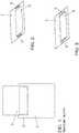
- a metal composite film 2 is shown in an oblique view.
- the metal composite film 2 has already gone through a deep-drawing process and has a cavity 5 for receiving a cell stack (not shown).
- To the right and left of the cavity 5 there are two areas 6 in which a texture has been introduced into the surface of the metal composite film 2. The process of introducing the texture is explained in more detail below.
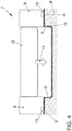
- Figure 3 is the metal composite film 2 after Figure 2 shown in a subsequent processing state, in which a pre-sealing tape 3 has been applied to the texture 6 and has been connected to the metal composite film 2 in a captive manner.
- a pre-sealing tape 3 has been applied to the texture 6 and has been connected to the metal composite film 2 in a captive manner.
- the manufacturing process of this metal composite film 2 is described below with reference to FIG Figures 4 and 5 explained in more detail.
- the Figure 4 shows a possible embodiment of a molding device 7 according to the invention for carrying out the method according to the invention.
- the molding device 7 consists of a die 8 and a sheet metal holder 9.
- the die 8 has a recess 10 which is formed in accordance with the cavity 5 which is to be formed in the metal composite film 2 after the deep-drawing process.
- the metal composite foil 2 is pressed by the sheet metal holder 9 in the direction of the arrow 11 against the die 8 and thus securely fixed in its position.
- a stamp 12 is also moved downward in the direction of the arrow 11, so that the metal composite film 2 undergoes a deformation and forms the desired cavity 5 within the recess 10.
- a texture 6 is introduced into a partial area of the surface of the metal composite film 2. This is done through inserts 13 that are inserted on the underside of the sheet metal holder 9, ie on the side facing the die 8, and have a surface which corresponds to the negative shape of the desired texture of the metal composite film 2.
- the inserts 13 are moved and controlled with the aid of gas pressure springs while generating a sufficiently large actuating force.
- the shaping device 7 designed in this way, the metal composite film 2 can be deep-drawn and provided with a texture 6 either in a single work step or in two work steps that follow one another or merge into one another. After both of these have taken place, the metal composite film 2 prepared in this way can be fed as a pouch for further processing to produce a pouch cell.
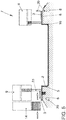
- FIG. 5 the molding device 7 is shown in a further processing state.
- the metal composite film 2 is in turn in the recess 10 of the die 8.
- the sheet metal holder 9 shown on the left is shown in an opened state.
- a pre-sealing tape 3 is fed from a magazine 14 in the direction of the arrows shown and comes to rest against a stop means, here stop 15.
- the stop 15 is integrated in the sheet metal holder 9 and moves into it as soon as the sheet metal holder 9 is moved downward against the die 8.
- the stop 15 is designed in such a way that the presealing tape 3 is arranged exactly over the texture 6.
- the sheet metal holder 9 as on the right side of the Figure 5 shown, downward method, wherein the pre-sealing tape 3 is firmly connected to the metal composite film 2 via the previously introduced texture 6, for example by gluing, welding or pressing.
- the pre-sealing tape 3 is firmly connected to the metal composite film 2 via the previously introduced texture 6, for example by gluing, welding or pressing.
- the metal composite foil 2 is cut exactly to the desired contour by means of a cutting tool 20.
- a cutting tool 20 Different embodiments are available for the execution of the cutting tool 20.
- a particularly simple embodiment with only one cutting knife is shown on the left-hand side of the figure. To cut the contour, this cutting knife is only moved upwards and in doing so reaches the blank holder 9, which acts as a cutting jaw Plant, whereby the metal composite foil foil 2 is cut to size.
- Another possible embodiment is shown on the right-hand side of the figure, in which two components form the cutting tool 20. One of the components is integrated in the sheet metal holder 9, while the second component is arranged in the die 8.
- the two components are positioned in such a way that when the sheet metal holder 9 is closed they shear off the metal composite foil at its outer edge and thus ensure a dimensionally accurate contour of the metal composite foil 2.
- the right side of the blank holder 9 acts as a cutting jaw when it is closed.
- the metal composite film 2 or pouch film produced in this way can then be removed together with the presealing tape 3 and processed further.
- two such processed metal composite foils 2 can then be used in order to arrange a cell stack including the associated arrester tabs and arrester tab 1 therein.
- the arrester tabs are arranged in such a way that they protrude as contacts from this arrangement.
- these pouch cells created in this way only have to be sealed by joining the edges of the metal composite film 2, the pre-sealing tape 3 permanently and tightly sealing the pouch cell 4, in particular at the exit points of the conductor tab 1.
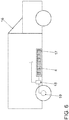
- a motor vehicle 16 which is equipped with a battery 17 in which a plurality of pouch cells 4 are arranged.
- the pouch cells 4 have been produced according to the method according to the invention.
- Such a battery 17 is inexpensive to manufacture and, moreover, has an extremely low level of heat development during operation, since the ohmic resistance within the pouch cells 4 is significantly reduced.
- the reduction of the ohmic resistance can be made possible through the use of area-based pressure welding (diffusion welding), which was previously not possible due to the interfering contour "pre-sealing tape".
- the energy provided by the battery 17 can be output as required to an electric motor 19 by means of a controller 18 in order to generate the drive power required in each case.
Landscapes
- Chemical & Material Sciences (AREA)
- Chemical Kinetics & Catalysis (AREA)
- Electrochemistry (AREA)
- General Chemical & Material Sciences (AREA)
- Inorganic Chemistry (AREA)
- Engineering & Computer Science (AREA)
- Manufacturing & Machinery (AREA)
- Sealing Battery Cases Or Jackets (AREA)
- Connection Of Batteries Or Terminals (AREA)
Abstract
a) Erzeugen einer Textur (6) in wenigstens einem Teilbereich der Metallverbundfolie (2);
b) Aufbringen eines Vorsiegelbandes (3) auf die Metallverbundfolie (2), wobei die Textur (6) zumindest teilweise von dem Vorsiegelband (3) überdeckt wird;
c) Verbinden des Vorsiegelbandes (3) mit der Metallverbundfolie (2) zu einem Verbund;
d) Zuschneiden des Verbunds auf eine vordefinierte Fertigkontur.
Description
- Die vorliegende Erfindung betrifft ein Verfahren und eine Vorrichtung zur Verbindung eines Vorsiegelbandes mit einer Metallverbundfolie für Pouchzellen.
- Im Stand der Technik sind verschiedene Arten von Batterien mit Pouchzellen bekannt, die in der Regel als galvanische Zellen ausgebildet sind. Derartige Pouchzellen, die i.A. als Batteriezellen bezeichnet werden, werden beispielsweise zur Bereitstellung von elektrischer Energie für den Antrieb von Fahrzeugen verwendet. Eine andere Anwendung ist die Versorgung von mobilen Geräten wie beispielsweise Mobilfunkgeräten, Tabletts oder Laptops mit elektrischer Energie für deren Betrieb. Aufgrund der ständig steigenden Anforderungen an derartige Batterien und die darin verbauten Batteriezellen ist ein es ein fortwährendes Bestreben die Herstellungskosten zu senken, die Lebensdauer der Batterien zu verlängern und gleichzeitig die Leistungsdichte, d. h. die pro Volumeneinheit gespeicherte elektrische Energiemenge, zu erhöhen.
- Die im Stand der Technik bekannten Pouchzellen bestehen grundsätzlich aus einer Anode, einer Kathode sowie einem dazwischen angeordneten Separator. Die Anode und die Kathode bilden die Elektroden der Pouchzellen. Der Separator dient dazu einen elektrischen Kontakt zwischen den beiden Elektroden zu verhindern. Weiterhin ist für die Funktion der Pouchzellen die Anwesenheit eines Elektrolyten erforderlich, der beide Elektroden benetzen bzw. durchsetzen muss. Die Elektroden selbst sind in der Regel aus mehreren Elektrodenbahnen aufgebaut, die ebenfalls durch Separatoren zueinander elektrisch isoliert werden.
- Der in der Pouchzellen erzeugte Strom wird mittels sogenannter Ableiterfähnchen von den jeweiligen Elektrodenbahnen abgeleitet. Die Ableiterfähnchen sind dazu elektrisch leitend mit den jeweiligen Elektrodenbahnen verbunden und leiten den Strom von dort zu einem Ableitertab, mit dem sie dazu ebenfalls elektrisch leitend verbunden sind. Die genannten Komponenten werden anschließend mit einer Metallverbundfolie dicht umschlossen, wobei die Ableitertabs der jeweiligen Elektrode zumindest teilweise aus dieser Umhüllung herausragen und die Anschlusspole der Batterie bilden. Für ein zuverlässiges und dauerhaft dichtes Abschließen der Metallverbundfolie ist im Bereich der Ableitertabs ein sogenanntes Vorsiegelband vorgesehen, welches für einen dichten Abschluss zwischen dem Ableitertab und der Metallverbundfolie sorgt.
- Bei den in der Praxis bekannten Lösungen erweisen sich die Vorsiegelbänder während der Ableiterschweißung als problematisch. Die Ableitertabs werden in der Regel durch Schweißen mit den Ableiterfähnchen der einzelnen Elektroden verbunden. Dies führt in der Regel zu einem Wärmeeintrag in dem Ableitertab, wodurch die temperaturempfindlichen Vorsiegelbänder beschädigt werden können. Um dies zu verhindern, ist es erforderlich die Ableitertabs und die Vorsiegelbänder während des Schweißprozesses ggf. sehr aufwendig und stetig zu kühlen. Alternativ wird der Abstand zwischen Schweißnaht und Vorsiegelband so gewählt, dass kein Wärmeintrag auf das Vorsiegelband einwirkt. In der Praxis kann der Abstand in der Regel allerdings nicht so groß ausfallen, da durch einen derart großen Abstand wertvoller Bauraum verloren geht. Das Vorsiegelband darf jedoch während der Fertigung weder beschädigt noch erwärmt werden, da es in einem späteren Prozessschritt eine stoffschlüssige Verbindung mit der Metallverbundfolie, die auch als Pouchfolie bezeichnet wird, eingehen muss. In der Praxis werden Ableitertabs in der Regel zusammen mit den zugehörigen Vorsiegelbänder als vorgefertigte einteilige Produkte beschafft.
- Bedingt durch die vorgenannten Einschränkungen können derzeit auch nur bestimmte Schweißverfahren wie beispielsweise Punktschweißen, Widerstandsschweißen oder Linearschweißen (Laserschweißen) für die Fertigung der Ableitertabs verwendet werden. Die Verwendung von Flächenschweißen (auch Druckschweißen genannt) ist nicht möglich, da dies zu Beschädigungen der Vorsiegelbänder führen würde.
- Die bislang bekannten Lösungen haben zudem weitere Nachteile. So muss der für die Verbindung der Ableiterfähnchen der Elektroden mit dem Ableitertab erforderliche Schweißprozess aufwendig und stetig gekühlt werden. Dabei muss sichergestellt werden, dass das Vorsiegelband nicht beschädigt bzw. erwärmt wird, um im weiteren Herstellungsprozess eine stoffschlüssige Verbindung mit der Metallverbundfolie zu gewährleisten. Ferner besteht der Nachteil, dass nur bestimmte Schweißverfahren verwendet werden können und so die elektrische Verbindung zwischen Ableiterfähnchen und dem Ableitertab einen relativ hohen elektrischen Widerstand aufweist. Außerdem muss während des Herstellungsprozesses zwischen dem Ableitertab und dem Vorsiegelband eine Transportsicherung vorgesehen werden, um ein unbeabsichtigtes Verlieren des Vorsiegelbandes zu verhindern.
- Aufgabe der vorliegenden Erfindung ist es daher, die sich aus dem Stand der Technik ergebenden Probleme zumindest teilweise zu lösen. Insbesondere soll ein Verfahren zur Verarbeitung einer Metallverbundfolie für Pouchzellen angegeben werden, das den Fertigungsprozess vereinfacht und die elektrischen Eigenschaften der Pouchzellen und damit der gesamten Batterie verbessert.
- Zur Lösung dieser Aufgaben trägt ein Verfahren mit den Merkmalen gemäß Patentanspruch 1 bei. Vorteilhafte Weiterbildungen sind Gegenstand der abhängigen Patentansprüche. Die in den Patentansprüchen einzeln aufgeführten Merkmale sind in technologisch sinnvoller Weise miteinander kombinierbar und können durch erläuternde Sachverhalte aus der Beschreibung und/oder Details aus den Figuren ergänzt werden, wobei weitere Ausführungsvarianten der Erfindung aufgezeigt werden.
- Vorliegend wird ein Verfahren zur Verbindung eines Vorsiegelbandes mit einer Metallverbundfolie für Pouchzellen vorgeschlagen, welches wenigsten die folgenden Schritte aufweist:
- a) Erzeugen einer Textur in wenigstens einem Teilbereich der Metallverbundfolie;
- b) Aufbringen eines Vorsiegelbandes auf die Metallverbundfolie, wobei die Textur zumindest teilweise von dem Vorsiegelband überdeckt wird;
- c) Verbinden des Vorsiegelbandes mit der Metallverbundfolie zu einem Verbund;
- d) Zuschneiden des Verbunds auf eine vordefinierte Fertigkontur.
- Im Schritt a) wird zunächst in wenigstens einem Teilbereich der Metallverbundfolie eine Textur erzeugt. Eine Textur kann als eine regelmäßige oder unregelmäßige Erhöhung oder Vertiefung an der Oberfläche der Metallverbundfolie ausgebildet werden. Die Textur kann als einzelne Erhöhung oder Vertiefung oder durch eine Vielzahl von Erhöhungen oder Vertiefungen ausgebildet werden. Die Textur kann beispielsweise nach Art eines Musters ausgeführt sein. Beispielsweise kann die Textur in verschiedene Richtungen regelmäßige Erhöhungen und Vertiefungen aufweisen. Die Vertiefung können sich dabei auch durch eine gesamte Wandstärke der Metallverbundfolie hindurch erstrecken, sodass die Metallverbundfolie an diesen Stellen durchbrochen ist. Texturen können durch Verprägungen erzeugt werden, wie beispielsweise punktförmige Erhöhungen bzw. Vertiefungen oder linienförmige Rippen oder Vertiefungen. Texturen können insbesondere auch in Form sich wiederholender Muster, wie beispielsweise sich kreuzender Linien, ausgeführt werden. Die Texturen werden dabei bevorzugt mit einem Werkzeug, insbesondere einem Einsatz, eingeprägt.
- Gemäß Schritt b) wird das Vorsiegelband auf die Metallverbundfolie aufgebracht, wobei es den mit der Textur versehenen Bereich der Metallverbundfolie zumindest teilweise überdeckt. Schritt b) kann insbesondere nach Abschluss des Schrittes a) durchgeführt werden. Es ist beispielsweise möglich, dass das Vorsiegelband in Schritt b) auf der Metallverbundfolie (automatisch) an einer vorgegebenen Stelle platziert wird.
- Schritt c) dient dazu, das Vorsiegelband mit der Metallverbundfolie zu einem Verbund zu verbinden und anschließend auf die benötigte und vordefinierte Kontur zuzuschneiden. Während des Verbindungsprozesses werden Vorsiegelband und Metallverbundfolie zueinander fixiert und dann das Verbinden mit oder ohne Fügemittel bevorzugt unter Raumtemperatur durchgeführt. Hierbei wird im Bereich der Textur bevorzugt durch Druck eine Adhäsion und/oder ein Formschluss zwischen der Metallverbundfolie und dem Vorsiegelband erzeugt.
- Das Zuschneiden gemäß Schritt d) erfolgt in einem Trennschritt insbesondere mittels eines trennenden Verfahrens, bei dem der Randbereich der Metallverbundfolie maßgenau beschnitten wird. Hierbei ist es insbesondere möglich die Schritte c) und d) kombiniert in einem gemeinsamen Verfahrensschritt auszuführen.
- Auf diese Weise kann der Prozessschritt der Verbindung der Metallverbundfolie mit dem Vorsiegelband gemeinsam mit dem Trennschnitt der Folie erfolgen. Der Trennschnitt ist aufgrund der durch die Umformung entstehenden unstetigen Ränder der Folie notwendig. Ferner wird durch den Trennschnitt das spätere Zielmaß der Pouchfolie erreicht. Durch die gemeinsame Ausführung der Verbindung und des Trennschnitts erhöht sich die Wirtschaftlichkeit des Herstellungsprozesses erheblich.
- Die so hergestellte Metallverbundfolie kann danach in besonders einfacher Weise für den Herstellungsprozess einer Pouchzelle bzw. einer Batterie bestehend aus mehreren Pouchzellen verwendet werden. Dies liegt daran, dass das Vorsiegelband sicher an der Metallverbundfolie angeordnet ist und nicht wie bisher am Ableitertab. Dies hat gleich mehrere Vorteile. Zum einen entfällt damit die Wärmeempfindlichkeit des Ableitertabs zum Beispiel während des Schweißens und es können auch andere besonders vorteilhafte Schweißverfahren, wie das Druckschweißen verwendet werden, wodurch der ohmsche Widerstand der Pouchzelle reduziert werden kann.
Der Vorteil des Druckschweißens besteht darin, dass auf diesem Wege elektrische Verbindungen geschaffen werden können, die einen wesentlich kleineren elektrischen Widerstand aufweisen. Die zu leitenden Elektronen müssen damit nicht mehr ihren Weg von einem Bauteil zum anderen über kleine Verbringungen nehmen, sondern können die gesamte Kontaktfläche zwischen dem Bauteil nutzen, wodurch der ohmsche Leistungsverlust signifikant verringert wird und sich die Pouchzellen bei Energieabgabe oder Energieaufnahme deutlich weniger erwärmen. - Ein anderer Vorteil der Anordnung des Vorsiegelbandes auf der Metallverbundfolie besteht darin, dass die Ableitertabs während des Schweißprozesses nicht mehr ständig gekühlt werden müssen. Hierdurch vereinfacht sich der Fertigungsprozess erheblich. Weiterhin können auch die bislang erforderlichen Transportsicherungen zur Positionierung der Vorsiegelbänder mit den Ableitertabs entfallen, weil das Vorsiegelband nun sicher mit der Metallverbundfolie verbunden ist und so einfach und verliersicher dem Herstellungsprozess zugeführt werden kann. So war beispielsweise bislang erforderlich das Vorsiegelband durch einen Kleber oder mittels eines Schweißverfahrens an dem Ableitertab zu sichern. Dieser Arbeitsschritt kann durch die hier vorgeschlagene Lösung entfallen und es wird ermöglicht, einen weiteren Werkstoff bzw. ein weiteres Fügemittel, wie beispielsweise ein Kleber, zu vermeiden.
- Schließlich müssen nun nicht mehr die Ableitertab zusammen mit den Vorsiegelbänder vorkonfektioniert beschafft werden, wodurch sich zudem die Beschaffungskosten reduzieren lassen.
- Insbesondere kann vorgesehen werden, dass das Verbinden des Vorsiegelbandes mit der Metallverbundfolie mittels Adhäsion und/oder Formschluss durch die vorher aufgebrachte Textur durchgeführt wird. Dazu wird das Vorsiegelband gegen die Textur gepresst, so dass das eine zuverlässige Verbindung zwischen diesen beiden Bauteilen entsteht. Unter Adhäsion ist dabei die Erzeugung von Haftkräften zwischen dem Vorsiegelband und der Metallverbundfolie zu verstehen. Dies kann beispielsweise durch Verpressen der beiden Bauteile mit oder ohne Textur unter Druck geschehen. Alternativ können auch Hilfsstoffe eingesetzt werden, die nach Art eines Klebstoffes für die Adhäsion zwischen den Bauteilen sorgen.
- Ein Vorteil der vorliegenden Erfindung besteht darin, dass die Verbindung der Metallverbundfolie mit dem Vorsiegelband in den zwei nachfolgenden Prozessschritten Tiefziehen und Trennschnitt integriert durchgeführt werden kann. Hierbei kann der Vorteil der Vereinfachung des Herstellerprozesses realisiert werden.
- Insbesondere ist es auch vorteilhaft, wenn die Metallverbundfolie vor dem Erzeugen der Textur an der Oberfläche der Metallverbundfolie in eine Formvorrichtung mit einer Aussparung eingelegt wird. Dazu kann die Metallverbundfolie beispielsweise auf eine Matrize aufgelegt werden, wobei die Matrize eine solche Aussparung aufweist, die der Form entspricht, die die fertige Metallverbundfolie bzw. Pouchfolie später aufweisen soll. Die Metallverbundfolie kann dabei von einem Blechhalter sicher in der Matrize fixiert werden, um einen sicheren Halt während der Bearbeitung sicherzustellen. Der Blechhalter funktioniert dabei im eigentlichen Sinne als Folienhalter bzw. Niederhalter für die zu bearbeitende Pouchfolie.
- Insbesondere ist es auch vorteilhaft, die Textur auf der Metallverbundfolie im Schritt a) durch einen Einsatz im Blechhalter in der Formvorrichtung zu erzeugen. Hierzu schließt ein im Blechhalter oder ein separat vorgesehener Einsatz kurz vor dem bzw. am Ende des Umformprozesses, um die gewünschte Textur in der Metallverbundfolie zu erzeugen. Das Erzeugen der Textur kann gleichzeitig während des Trennvorgangs oder danach durchgeführt werden. Zur Fixierung der Metallverbundfolie kann beispielsweise der Blechhalter, der ein Bestandteil der Formvorrichtung ist, verwendet werden. Dies geschieht, indem die Metallverbundfolie zunächst auf die Matrize aufgelegt wird. Danach wird der Blechhalter in Richtung der Matrize verfahren und presst dabei die Metallverbundfolie gegen die Matrize.
- Insbesondere vorteilhaft ist es, wenn der Schritt der Erzeugung der Textur vor dem Schritt a) oder zumindest kurz vor Ende des Tiefziehprozesses ausgeführt wird. Kurz vor dem Ende bedeutet dabei, dass der Umformprozess bereits zu mehr als 80%, vorzugsweise zu mehr als 90% abgeschlossen ist und keine größeren Veränderungen im Randbereich der Metallverbundfolie mehr zu erwarten sind. Auf diese Weise kann die Textur bereits am Ende der Umformung oder kurz danach auf die Metallverbundfolie eingebracht werden. Der Materialfluss unter dem Blechhalter während des Tiefziehens wird durch diesen Prozess nicht beeinflusst. Dies kann beispielsweise durch einfache Einsätze erreicht werden, die im Blechhalter vorgesehen sind und Blechhalter kurz vor Ende der Umformung über separate Gasdruckfedern auf die Oberfläche der Metallverbundfolie einwirken, um so eine gewünschte Textur zu erzeugen.
- Für die Umsetzung des Umformvorgangs, der insbesondere als Tiefziehvorgang mit Stempel und Matrize ausgestaltet sein kann, stehen unterschiedliche bekannte Verfahren und Methoden, die beispielsweise einen Stempel und eine komplementär geformte Matrize verwenden, zur Verfügung.
- Insbesondere kann die Metallverbundfolie in einem Verfahrensschritt innerhalb einer Kavität umgeformt werden. Dieser Verfahrensschritt kann grundsätzlich vor, während oder nach den Verfahrensschritten a) bis d) erfolgen. Die Durchführung der Umformung kann in Abhängigkeit von der Art des gewählten Tiefziehprozesses erfolgen. So kann der Tiefziehvorgang beispielsweise mittels eines Stempels, mittels elektromagnetischer Impulsumformung und/oder mittels Druckluft erfolgen. Ein Vorteil der vorliegenden Erfindung besteht darin, dass der Tiefziehvorgang und die Schritte a) bis d) in einem Verfahrensablauf integriert ausgeführt werden können, ohne örtlich umpositioniert werden zu müssen.
- Besonders vorteilhaft ist es, wenn als Metallverbundfolie eine Aluminium-Verbundfolie verwendet wird. Derartige Folien sind gut verfügbar und haben sich für die Ummantelung von Pouchzellen bereits bewährt. Die Folien bestehen in der Regel aus verschiedenen Kunststoffschichten, wobei die Basis eine ca. 40µm dicke Aluminiumfolie ist. Die Aluminiumfolie ist auf beiden Seiten von verschiedenen Kunststoffschichten ummantelt, die für die Umformung, Isolierung und spätere stoffschlüssige Verbindung notwendig sind. Somit ergeben sich Foliendicken zwischen ca. 120µm und 180µm [Mikrometer], die je nach Hersteller und Anforderung variieren können.
- Insbesondere kann mit wenigstens einer Metallverbundfolie der hier vorgeschlagenen Art, einem Zellstapel, einem Ableitertab und einem Ableiterfähnchen auch ein Verfahren zu Herstellung einer Pouchzelle mit folgenden Schritten durchgeführt werden:
- A) Verbinden des Ableitertabs mit dem Ableiterfähnchen,
- B) Zusammenführen des Ableitertabs mit dem Zellstapel;
- C) Umhüllen des Zellstapels und des Ableitertabs mit wenigstens einer Metallverbundfolie;
- D) Versiegeln der Metallverbundfolie.
- Durch die Einbringung des Vorsiegelbandes auf die Pouchfolie und die somit bessere Möglichkeit der Schweißung von Ableitertabs und Ableiterfähnchen des Zellstapels wird die Herstellung von Pouchzellen erleichtert. Damit wiederum wird auch die Fertigung von Pouchzellen in erheblichem Maß verbessert. Durch die Einhaltung der beschriebenen Prozessreihenfolge kann eine Metallverbundfolie mit einer sehr präzisen Randkontur hergestellt werden. Zudem können die Vorsiegelbänder besonders genau auf der Metallverbundfolie positioniert werden. Diese erhöhte Fertigungsgenauigkeit wirkt sich vorteilhaft auf den nachfolgenden Fertigungsschritt zur Herstellung der Pouchzellen aus. Durch die präzise gefertigte Metallverbundfolie ist in diesem späteren Schritt die Genauigkeit der Positionierung von der Pouchfolie inkl. Vorsiegelband zu dem Ableitertab gewährleistet. Außerdem ist der zusätzliche Prozessschritt der Positionierung und Transportsicherung des Vorsiegelbandes zu dem Ableitertab nicht länger notwendig.
- Die nach diesem Verfahren gestaltete Pouchzelle kann in besonders einfacher Weise ohne zusätzliche Kühlung der Ableiter während des Verbindens mit den Ableiterfähnchen hergestellt werden. Zudem können die zur Umhüllung des Zellstapels verwendeten Metallverbundfolien im Schritt C) besonders einfach und zuverlässig versiegelt werden, da die Vorsiegelbänder bereits sicher an der Metallverbundfolie angeordnet sind. Weitergehende Transportsicherungen zur Sicherung der Vorsiegelbänder an den Ableitertabs werden nicht mehr benötigt. Die Verwendung der hier vorgeschlagenen Metallverbundfolie bei der Herstellung von Pouchzellen erleichtert somit in erheblichem Maß die Fertigung dieser Zellen.
- Besonders bevorzugte Ausführungsformen von Pouchzellen sehen dabei die Verwendung von zwei Metallverbundfolien vor, die zuvor mittels eines Tiefziehvorgangs in die benötigte Form gebracht wurden. Die beiden Metallverbundfolie umhüllenden dann einen Zellstapel. Der in diesem Zellstapel erzeugte Strom wird dann mittels einer Vielzahl von Ableiterfähnchen und über zwei Ableitertabs an einen Verbraucher abgegeben. Die Ableiterfähnchen sind dabei je nach Polung mit einem der beiden Ableitertabs elektrisch verbunden, sodass alle mit einer Kathode verbundenen Ableiterfähnchen an einem ersten Ableitertab und alle mit einer Anode verbundenen Ableiterfähnchen an einem zweiten Ableitertab angeschlossen sind.
- Zur Lösung der Aufgabenstellung wird weiterhin ein Vorrichtung zur Herstellung von Metallverbundfolien für Pouchzellen mit einer Matrize vorgeschlagen, die dadurch gekennzeichnet ist, dass die Matrize zu der vorgeformten Metallverbundfolie komplementär ausgebildet ist, eine Zuführvorrichtung zur Zuführung von Vorsiegelband zur Matrize und ein Anschlagmittel zur Positionierung des Vorsiegelbands auf der Matrize aufweist, ferner ein Blechhalter, der zum Verbinden des Vorsiegelbands mit der Metallverbundfolie ausgebildet ist, und ein Schneidwerkzeug zum Beschneiden der Metallverbundfolie. vorgesehen sind. Mit einer derart gestalteten Vorrichtung können vorgeformte Metallverbundfolien, die beispielsweise zuvor mittels eines Tiefziehvorgangs in eine gewünschte halbschalenförmige Form gebracht worden sind, mit dem Vorsiegelband verliersicher verbunden und maßgenau zugeschnitten werden. Hierbei können die Schritte der Zuführung des Vorsiegelbands, des Verbindens von Vorsiegelband mit der Metallverbundfolie und des Zuschnitts an einer Fertigungsstation ausgeführt werden. Dies steigert die Effizienz der Fertigung erheblich, da zwischen diesen Schritten kein Weitertransport erforderlich ist. Vorzugsweise werden die Schritte auch automatisiert ausgeführt. Hierzu kann das Magazin eine Mehrzahl von Vorsiegelbändern bereithalten, die von einer Fördereinrichtung zur Matrize gefördert werden. Dort gelangen die Vorsiegelbänder zur Anlage an Anschlagmittel, die beispielsweise als federnd gelagerte bewegliche Bolzen im Blechhalter ausgeführt sind, und werden so genau Positionierung über der Metallverbundfolie positioniert. Nach der Zuführung und der Positionierung erfolgt dann das Verbinden von Vorsiegelband und Metallverbundfolie. Dies kann beispielsweise durch Aufschweissen mittels das Blechhalters erfolgen. Der Blechhalter kann dazu die entsprechend große Anpresskraft auf den Verbund von Vorsiegelband und Metallverbundfolie ausüben und/oder für einen ausreichend hohen Temperatureintrag in den Verbund sorgen. Schließlich wird der Verbund noch in die gewünschte Form gebracht, in dem vorzugsweise die umlaufende Aussenkante mittels des Schneidwerkzeugs formgenau und maßgenau zugeschnitten wird.
- Vorzugsweise ist dabei das Schneidwerkzeug in den Blechhalter integriert. Hierdurch kann die Vorrichtung kompakter gebaut werden. Zudem kann bei dieser Ausgestaltung der Schritt des Verbindens gleichzeitig mit dem Zuschnitt der Außenkontur im Trennschritt ausgeführt werden.
- Insbesondere ist dabei vorteilhafterweise das Anschlagmittel in den Blechhalter integriert. Hierdurch ist es beispielsweise möglich die Positionierung des Vorsiegelbands bei geöffnetem Blechhalter vorzunehmen und beim Schließen des Blechhalters gleichzeitig das Verbinden und den Zuschnitt auszuführen.
- Schließlich können derartige Pouchzellen vorteilhaft in Kraftfahrzeugen eingesetzt werden, da sie günstig in der Herstellung sind und zudem aufgrund des verbesserten und reduzierten ohmschen Widerstands bessere elektrische Eigenschaften aufweisen. Die bestehen beispielsweise darin, dass sich die Pouchzellen während des Betriebes nicht oder zumindest deutlich weniger erwärmen und eine höhere Leistungsabgabe erbringen können.
- Vorsorglich sei angemerkt, dass die hier verwendeten Zahlwörter ("erste", "zweite", ...) vorrangig (nur) zur Unterscheidung von mehreren gleichartigen Gegenständen, Größen oder Prozessen dienen, also insbesondere keine Abhängigkeit und/oder Reihenfolge dieser Gegenstände, Größen oder Prozesse zueinander zwingend vorgeben. Sollte eine Abhängigkeit und/oder Reihenfolge erforderlich sein, ist dies hier explizit angegeben oder es ergibt sich offensichtlich für den Fachmann beim Studium der konkret beschriebenen Ausgestaltung.
- Die Erfindung sowie das technische Umfeld werden nachfolgend anhand der beiliegenden Figuren näher erläutert. Es ist darauf hinzuweisen, dass die Erfindung durch die angeführten Ausführungsbeispiele nicht beschränkt werden soll. Insbesondere ist es, soweit nicht explizit anders dargestellt, auch möglich, Teilaspekte der in den Figuren erläuterten Sachverhalte zu extrahieren und mit anderen Bestandteilen und Erkenntnissen aus der vorliegenden Beschreibung zu kombinieren. Insbesondere ist darauf hinzuweisen, dass die Figuren und insbesondere die dargestellten Größenverhältnisse nur schematisch sind. Es zeigen:
-
Fig.1 : einen Ableitertab mit Metallverbundfolie und Vorsiegelband nach dem Stand der Technik; -
Fig. 2 : eine tiefgezogene Metallverbundfolie mit Textur; -
Fig. 3 : eine tiefgezogene Metallverbundfolie mit Textur und Vorsiegelband; -
Fig. 4 : eine seitliche Schnittansicht einer erfindungsgemäßen Formvorrichtung während des Tiefziehens; -
Fig. 5 : eine seitliche Schnittansicht einer erfindungsgemäßen Formvorrichtung während des Aufbringens des Vorsiegelbandes; und -
Fig. 6 : ein Kraftfahrzeug mit Pouchzellen gemäß der vorliegenden Erfindung; - In
Figur 1 ist ein Ableitertab 1 mit einer Metallverbundfolie 2 (Pouch) und einem Vorsiegelband 3 dargestellt. Der Ableitertab 1 besteht aus einem elektrisch leitenden Metall, wie beispielsweise Aluminium, Kupfer oder Stahl und dient im fertig montierten Zustand als Kontakt einer in dieser Ansicht nicht gezeigten Pouchzelle 4. Die Metallverbundfolie 2 besteht aus einer sehr dünnen Metallschicht, die auf einer Trägerschicht aufgebracht ist. Die Trägerschicht kann beispielsweise aus einem Kunststoff wie etwa Polypropylen oder Polyethylen bestehen. Im fertig montierten Zustand muss gemäß dem Stand der Technik die Kunststoffseite der Metallverbundfolie 2 mit dem Ableitertab 1 verbunden werden, wobei zwischen beiden Bauteilen das Vorsiegelband 3 angeordnet wird, um ein dauerhaft dichtes Abschließen der Pouchzellen 4 nach außen zu gewährleisten. Dies ist erforderlich, um ein Austreten von Elektrolyt oder ein Eindringen von Fremdstoffen in die Pouchzellen 4 zu verhindern. Die für die Funktion der Pouchzellen 4 ebenfalls erforderlichen Ableiterfähnchen müssen danach noch mit dem Ableitertab 1 verbunden werden, um die Funktionsfähigkeit der Pouchzellen 4 zu erreichen. Nach dem Stand der Technik erfolgt dies mittels Versschweißung, wobei der Ableitertab 1 fortlaufend gekühlt werden muss, da andernfalls ein Wärmeeintrag in das Vorsiegelband 3 erfolgen und zu einer Beschädigung desselbigen führen würde. Die Herstellung von Pouchzellen nach dem Stand der Technik ist somit sehr umständlich und fehleranfällig. - In
Figur 2 ist eine Metallverbundfolie 2 in einer Schrägansicht dargestellt. Die Metallverbundfolie 2 hat bereits einen Tiefziehprozess durchlaufen und weist eine Kavität 5 zur Aufnahme eines nicht dargestellten Zellstapels auf. Rechts und links der Kavität 5 befinden sich zwei Bereiche 6 in denen eine Textur in die Oberfläche der Metallverbundfolie 2 eingebracht worden ist. Der Vorgang der Einbringung der Textur wird nachfolgend noch näher erläutert. - In
Figur 3 ist die Metallverbundfolie 2 nachFigur 2 in einem nachfolgenden Bearbeitungszustand dargestellt, bei dem auf der Textur 6 ein Vorsiegelband 3 aufgebracht und verliersicher mit der Metallverbundfolie 2 verbunden worden ist. Der Fertigungsvorgang dieser Metallverbundfolie 2 wird nachfolgend anhand derFiguren 4 und5 näher erläutert. - Die
Figur 4 zeigt eine mögliche Ausführungsform einer erfindungsgemäßen Formvorrichtung 7 zur Durchführung des erfindungsgemäßen Verfahrens. Die Formvorrichtung 7 besteht aus einer Matrize 8 und einem Blechhalter 9. Die Matrize 8 weist eine Aussparung 10 auf, die entsprechend der Kavität 5 ausgebildet ist, welche nach dem Tiefziehvorgang in der Metallverbundfolie 2 ausgebildet werden soll. Die Metallverbundfolie 2 wird vom Blechhalter 9 in Richtung des Pfeils 11 gegen die Matrize 8 gepresst und somit sicher in ihrer Lage fixiert. Nachdem die Metallverbundfolie 2 auf diese Weise sicher fixiert ist, wird ein Stempel 12 ebenfalls in Richtung des Pfeils 11 nach unten verfahren, sodass die Metallverbundfolie 2 eine Verformung erfährt und innerhalb der Aussparung 10 die gewünschte Kavität 5 ausbildet. Kurz vor Ende des Tiefziehens oder kurz danach wird in einem Teilbereich der Oberfläche der Metallverbundfolie 2 eine Textur 6 eingebracht. Dies geschieht durch Einsätze 13, die an der Unterseite des Blechhalters 9, d. h. an der der Matrize 8 zugewandten Seite, eingesetzt sind und eine Oberfläche aufweisen, welche der Negativform der gewünschten Textur der Metallverbundfolie 2 entspricht. Die Einsätze 13 werden mit Hilfe von Gasdruckfedern unter Erzeugung einer ausreichend großen Betätigungskraft bewegt und gesteuert. Mit der so ausgebildeten Formvorrichtung 7 kann die Metallverbundfolie 2 entweder in einem einzigen Arbeitsschritt oder in zwei unmittelbar aufeinander folgenden bzw. ineinander übergehenden Arbeitsschritten tiefgezogen und mit einer Textur 6 versehen werden. Nachdem dies beides erfolgt ist, kann die so vorbereitete Metallverbundfolie 2 als Pouch der weiteren Verarbeitung zur Herstellung einer Pouchzelle zugeführt werden. - In
Figur 5 ist die Formvorrichtung 7 in einem weiteren Bearbeitungszustand dargestellt. Dabei liegt die Metallverbundfolie 2 wiederum in der Aussparung 10 der Matrize 8. Der auf der linken Seite dargestellte Blechhalter 9 ist in einem aufgefahrenen Zustand dargestellt. Aus einem Magazin 14 wird ein Vorsiegelband 3 in Richtung der dargestellten Pfeile zugeführt und gelangen an einem Anschlagmittel, hier Anschlag 15 zur Anlage. Der Anschlag 15 ist in den Blechhalter 9 integriert und fährt in diesen ein, sobald der Blechhalter 9 nach unten gegen die Matrize 8 verfahren wird. Der Anschlag 15 ist so ausgelegt, dass das Vorsiegelband 3 exakt über der Textur 6 angeordnet ist. Anschließend wird der Blechhalter 9, wie auf der rechten Seite derFigur 5 dargestellt, nach unten Verfahren, wobei das Vorsiegelband 3 über die zuvor eingebrachte Textur 6 beispielsweise durch Kleben, Schweißen oder Pressen fest mit der Metallverbundfolie 2 verbunden wird. Auf diese Weise kann eine transportsichere Verbindung des Vorsiegelbandes mit der Metallverbundfolie 2 geschaffen werden. - Gleichzeitig mit dem Zufahren des Blechhalter 9 oder in einem nachfolgenden separaten Arbeitsschritt wird die Metallverbundfolie 2 mittels eines Schneidwerkzeugs 20 exakt auf die gewünschte Kontur zugeschnitten. Für die Ausführung des Schneidwerkzeugs 20 stehen unterschiedliche Ausführungsformen zur Verfügung. So ist auf der linken Seite der Figur eine besonders einfache Ausführungsform mit nur einem Schneidmesser dargestellt. Zum Zuschneiden der Kontur wird dieses Schneidmesser lediglich nach oben bewegt und gelangt dabei an dem als Schneidbacke wirkenden Blechhalter 9 zur Anlage, wobei die Metallverbundfolie Folie 2 zugeschnitten wird. Auf der rechten Seite der Figur ist eine andere mögliche Ausführungsform dargestellt, bei der zwei Bauteile das Schneidwerkzeug 20 bilden. Eines der Bauteile ist im Blechhalter 9 integriert, während das zweite Bauteil in der Matrize 8 angeordnet ist. Die beiden Bauteile sind so positioniert, dass sie bei einem Zufahren des Blechhalters 9 die Metallverbundfolie an ihrem äußeren Rand abscheren und somit für eine maßgenaue Kontur der Metallverbundfolie 2 sorgen. Auch hier wirkt die rechte Seite des Blechhalter 9 beim Zufahren als Schneidbacke.
- Die so gefertigte Metallverbundfolie 2 bzw. Pouchfolie kann danach zusammen mit dem Vorsiegelband 3 entnommen und weiterverarbeitet werden. Zur Herstellung einer Pouchzellen können dann zwei solcher bearbeiteten Metallverbundfolien 2 verwendet werden, um einen Zellstapel einschließlich der zugehörigen Ableiterfähnchen und Ableitertab 1 darin anzuordnen. Dabei werden die Ableitertabs so angeordnet, dass sie als Kontakte aus dieser Anordnung herausragen. Anschließend muss diese so geschaffene Pouchzellen nur noch durch Zusammenfügen der Ränder der Metallverbundfolie 2 versiegelt werden, wobei das Vorsiegelband 3 insbesondere an den Austrittsstellen der Ableitertab 1 die Pouchzelle 4 dauerhaft und dicht abschließt.
- In
Figur 6 ist schließlich ein Kraftfahrzeug 16 dargestellt, das mit einer Batterie 17 ausgestattet ist in welcher eine Vielzahl von Pouchzellen 4 angeordnet sind. Die Pouchzellen 4 sind dabei nach dem erfindungsgemäßen Verfahren hergestellt worden. Eine derartige Batterie 17 ist kostengünstig in der Herstellung und weist zudem während des Betriebes eine außerordentlich geringe Wärmeentwicklung auf, da der ohmsche Widerstand innerhalb der Pouchzellen 4 deutlich reduziert ist. Die Verringerung des ohmschen Widerstands kann durch den Einsatz von flächenbasiertem Druckschweißen (Diffusionsschweißen) ermöglicht werden, was vorher durch die Störkontur "Vorsiegelband" nicht möglich war. Die so von der Batterie 17 bereitgestellte Energie kann bei einem so gestalteten Fahrzeug mittels einer Steuerung 18 bedarfsgerecht an einen Elektromotor 19 abgegeben werden, um die jeweils benötigte Antriebsleistung zu erzeugen. -
- 1
- Ableitertab
- 2
- Metallverbundfolie
- 3
- Vorsiegelband
- 4
- Pouchzelle
- 5
- Kavität
- 6
- Textur
- 7
- Formvorrichtung
- 8
- Matrize
- 9
- Blechhalter
- 10
- Aussparung
- 11
- Pfeil
- 12
- Stempel
- 13
- Einsatz
- 14
- Magazin
- 15
- Anschlag
- 16
- Kraftfahrzeug
- 17
- Batterie
- 18
- Steuerung
- 19
- Elektromotor
- 20
- Schneidwerkzeug
Claims (12)
- Verfahren zur Verbindung eines Vorsiegelbandes mit einer Metallverbundfolie (2) für Pouchzellen (4), das wenigsten die folgenden Schritte aufweist:a) Erzeugen einer Textur (6) in wenigsten einem Teilbereich der Metallverbundfolie (2);b) Aufbringen eines Vorsiegelbandes (3) auf die Metallverbundfolie (2), wobei die Textur (6) zumindest teilweise von dem Vorsiegelband (3) überdeckt wird;c) Verbinden des Vorsiegelbandes (3) mit der Metallverbundfolie (2) zu einem Verbund;d) Zuschneiden des Verbunds auf eine vordefinierte Fertigkontur.
- Verfahren nach dem vorhergehenden Anspruch, wobei das Verbinden des Vorsiegelbandes (3) mit der Metallverbundfolie (2) mittels Adhäsion durch die vorher aufgebrachte Textur durchgeführt wird.
- Verfahren nach einem der vorhergehenden Ansprüche, wobei die Metallverbundfolie (2) vor dem Schritt a) in eine Formvorrichtung (7) mit einer Aussparung (10) eingelegt wird.
- Verfahren nach einem der vorhergehenden Ansprüche, wobei die Textur auf der Metallverbundfolie (2) im Schritt a) durch einen Einsatz im Blechhalter (9) in der Formvorrichtung (7) erzeugt wird.
- Verfahren nach einem der vorhergehenden Ansprüche, wobei die Metallverbundfolie (2) vor dem Schritt a) durch Tiefziehen umgeformt wird.
- Verfahren nach einem der vorhergehenden Ansprüche, wobei die Metallverbundfolie (2) in einem Verfahrensschritt umgeformt wird, währenddessen sie sich innerhalb der Aussparung (10) befindet.
- Verfahren nach einem der vorhergehenden Ansprüche, wobei als Metallverbundfolie (2) eine Aluminium-Verbundfolie verwendet wird.
- Verfahren nach einem der vorhergehenden Ansprüche, wobei eine Folienstärke der Metallverbundfolie (2) zwischen 120 µm und 180 µm gewählt wird.
- Verfahren zu Herstellung einer Pouchzelle (4) mit wenigstens einer Metallverbundfolie (2) hergestellt nach einem der vorhergehenden Ansprüche, einem Zellstapel, wenigstens einem Ableitertab und wenigstens einem mit dem Zellstapel verbundenen Ableiterfähnchen mit folgenden Schritten:A) Verbinden des Ableitertabs mit dem Ableiterfähnchen,B) Zusammenführen des Ableiters mit dem Zellstapel;C) Umhüllen des Zellstapels und des Ableitertabs mit wenigstens zwei Metallverbundfolien (2) nach einem der vorhergehenden Ansprüche.;D) Versiegeln der Metallverbundfolien (2)
- Vorrichtung zur Herstellung von Metallverbundfolien (2) für Pouchzellen (4) mit einer Matrize, dadurch gekennzeichnet, dass die Matrize (8) zu der vorgeformten Metallverbundfolie (2) komplementär ausgebildet ist, eine Zuführvorrichtung (14) zur Zuführung von Vorsiegelband (3) zur Matrize (8) und ein Anschlagmittel (15) zur Positionierung des Vorsiegelbands (3) auf der Matrize (8) aufweist, ferner ein Blechhalter (9), der zum Verbinden des Vorsiegelbands (3) mit der Metallverbundfolie (2) ausgebildet ist, und ein Schneidwerkzeug (20 zum Beschneiden der Metallverbundfolie (2). vorgesehen sind.
- Pouchzelle (4) hergestellt nach dem Verfahren gemäß dem Anspruch 9.
- Kraftfahrzeug (16) mit wenigstens einer Pouchzelle (4) nach dem vorhergehenden Patentanspruch.
Applications Claiming Priority (1)
| Application Number | Priority Date | Filing Date | Title |
|---|---|---|---|
| DE102020101087.7A DE102020101087A1 (de) | 2020-01-17 | 2020-01-17 | Verfahren und Vorrichtung zum Verbinden von Metallverbundfolien für Pouchzellen mit einem Vorsiegelband |
Publications (2)
| Publication Number | Publication Date |
|---|---|
| EP3852186A1 true EP3852186A1 (de) | 2021-07-21 |
| EP3852186B1 EP3852186B1 (de) | 2024-11-20 |
Family
ID=74125045
Family Applications (1)
| Application Number | Title | Priority Date | Filing Date |
|---|---|---|---|
| EP21150636.5A Active EP3852186B1 (de) | 2020-01-17 | 2021-01-08 | Verfahren und vorrichtung zum verbinden von metallverbundfolien für pouchzellen mit einem vorsiegelband |
Country Status (6)
| Country | Link |
|---|---|
| US (1) | US12074332B2 (de) |
| EP (1) | EP3852186B1 (de) |
| CN (1) | CN113140841B (de) |
| DE (1) | DE102020101087A1 (de) |
| ES (1) | ES3008361T3 (de) |
| HU (1) | HUE069684T2 (de) |
Families Citing this family (1)
| Publication number | Priority date | Publication date | Assignee | Title |
|---|---|---|---|---|
| DE102024133327A1 (de) * | 2024-11-14 | 2026-05-21 | Dr. Ing. H.C. F. Porsche Aktiengesellschaft | Herstellungsverfahren für eine Batteriezelle, sowie eine Batteriezelle |
Citations (3)
| Publication number | Priority date | Publication date | Assignee | Title |
|---|---|---|---|---|
| JP2004006124A (ja) * | 2002-05-31 | 2004-01-08 | Dainippon Printing Co Ltd | 電池およびその製造方法 |
| DE102010050046A1 (de) * | 2010-10-29 | 2012-05-03 | Li-Tec Battery Gmbh | Elektrochemiche Zelle und Verfahren zu deren Herstellung |
| DE102017217676A1 (de) * | 2017-10-05 | 2019-04-11 | Robert Bosch Gmbh | Batteriezelle und Verfahren zur Herstellung einer Batteriezelle |
Family Cites Families (7)
| Publication number | Priority date | Publication date | Assignee | Title |
|---|---|---|---|---|
| JP2004052100A (ja) * | 2002-05-27 | 2004-02-19 | Nippon Steel Corp | 電池用外装材 |
| KR101465172B1 (ko) * | 2012-12-24 | 2014-11-25 | 주식회사 엘지화학 | 내구성 향상을 위해 실링 마진을 가진 파우치형 이차 전지 |
| CN104981316B (zh) * | 2013-01-16 | 2018-02-27 | 纳谷系统株式会社 | 叠层金属箔的制造方法以及包含叠层金属箔的制造方法的密封型电池的制造方法 |
| DE102013021113A1 (de) * | 2013-12-13 | 2015-06-18 | Daimler Ag | Einzelzelle, Verfahren zur Herstellung einer Einzelzelle und elektrische Batterie |
| US20170137159A1 (en) * | 2015-11-13 | 2017-05-18 | Mystic Pharmaceuticals, Inc. | Deep Draw Container Forming Method and Nutritional Product Containers |
| CN108428814B (zh) * | 2017-02-15 | 2021-09-07 | 宁德新能源科技有限公司 | 包装膜及软包电池 |
| US11462723B2 (en) * | 2020-10-28 | 2022-10-04 | GM Global Technology Operations LLC | Electrochemical cells with copper-free electrodes and methods for manufacturing the same |
-
2020
- 2020-01-17 DE DE102020101087.7A patent/DE102020101087A1/de active Pending
-
2021
- 2021-01-08 HU HUE21150636A patent/HUE069684T2/hu unknown
- 2021-01-08 EP EP21150636.5A patent/EP3852186B1/de active Active
- 2021-01-08 ES ES21150636T patent/ES3008361T3/es active Active
- 2021-01-15 US US17/150,413 patent/US12074332B2/en active Active
- 2021-01-15 CN CN202110054156.8A patent/CN113140841B/zh active Active
Patent Citations (3)
| Publication number | Priority date | Publication date | Assignee | Title |
|---|---|---|---|---|
| JP2004006124A (ja) * | 2002-05-31 | 2004-01-08 | Dainippon Printing Co Ltd | 電池およびその製造方法 |
| DE102010050046A1 (de) * | 2010-10-29 | 2012-05-03 | Li-Tec Battery Gmbh | Elektrochemiche Zelle und Verfahren zu deren Herstellung |
| DE102017217676A1 (de) * | 2017-10-05 | 2019-04-11 | Robert Bosch Gmbh | Batteriezelle und Verfahren zur Herstellung einer Batteriezelle |
Also Published As
| Publication number | Publication date |
|---|---|
| HUE069684T2 (hu) | 2025-04-28 |
| CN113140841B (zh) | 2024-01-16 |
| ES3008361T3 (en) | 2025-03-24 |
| DE102020101087A1 (de) | 2021-07-22 |
| US12074332B2 (en) | 2024-08-27 |
| CN113140841A (zh) | 2021-07-20 |
| US20210226286A1 (en) | 2021-07-22 |
| EP3852186B1 (de) | 2024-11-20 |
Similar Documents
| Publication | Publication Date | Title |
|---|---|---|
| WO2017055057A1 (de) | Verfahren zur herstellung eines elektrodenverbundes | |
| DE102012217451A1 (de) | Batteriezelle mit in Gehäusedeckplatte integriertem Knackfederbereich | |
| EP2467885A1 (de) | Galvanische zelle mit rahmen und verfahren zu ihrer herstellung | |
| WO2013023766A1 (de) | Gehäusedeckel für einen elektrochemischen energiespeicher mit einem becherförmigen gehäuse und verfahren zur herstellung des gehäusedeckels | |
| WO2014040791A1 (de) | Batteriezelle mit in gehäusedeckplatte integrierter berstscheibe | |
| DE102022204913A1 (de) | Verfahren zur Herstellung einer Bipolarplatte | |
| DE102020213462A1 (de) | Verfahren zur Herstellung einer Batteriezelle | |
| DE102021101264A1 (de) | Leistungsspeichervorrichtung | |
| WO2016193050A1 (de) | Batteriemodulgehäuse, batteriemodul, deckelelement für ein solches batteriemodulgehäuse oder für ein solches batteriemodul, verfahren zur herstellung eines solchen batteriemoduls und batterie | |
| WO2011012210A1 (de) | Verfahren zum herstellen einer bipolaren rahmenflachzelle | |
| EP3852186B1 (de) | Verfahren und vorrichtung zum verbinden von metallverbundfolien für pouchzellen mit einem vorsiegelband | |
| DE102012220386A1 (de) | Batteriezelle mit Gehäusedeckplatte mit vernieteter Einfüllöffnung | |
| WO2016193447A1 (de) | Verfahren zum bördeln eines zumindest zweilagigen materials | |
| DE102012215661B4 (de) | Laserverschweißte Verbindung und elektrochemische Vorrichtung | |
| DE102018203570A1 (de) | Energiespeichervorrichtung | |
| WO2011012204A1 (de) | Elektrodenanordnung für eine batterieeinzelzelle | |
| DE102022124854A1 (de) | Metall-polymer-hybrid-stromkollektor für eine batterieelektrode und verfahren zu deren herstellung | |
| DE112019001570T5 (de) | Batteriemodul | |
| EP4039385A1 (de) | Verfahren und formvorrichtung zur umformung einer metallverbundfolie für batteriezellen | |
| EP3902055B1 (de) | Verfahren und vorrichtung zur herstellung von metall-verbundfolien für batteriezellen | |
| DE102024204049A1 (de) | Separatorplatte, Bipolarplatte, Verfahren und Rollprägeanordnung | |
| WO2011012200A1 (de) | Batterie und verfahren zum herstellen einer batterie | |
| DE102022211098A1 (de) | Batteriezelle sowie Verfahren zu deren Herstellung | |
| DE1596231A1 (de) | Verfahren zum Trennen der Elektroden von Zellenbatterien,Brennstoffzellen oder Akkumulatoren,insbesondere bei meerwasserzuendbaren Zellen,durch dieses Verfahren erhaltende Batterien und Vorrichtung zum Durchfuehren des Verfahrens | |
| DE102010050046A1 (de) | Elektrochemiche Zelle und Verfahren zu deren Herstellung |
Legal Events
| Date | Code | Title | Description |
|---|---|---|---|
| PUAI | Public reference made under article 153(3) epc to a published international application that has entered the european phase |
Free format text: ORIGINAL CODE: 0009012 |
|
| STAA | Information on the status of an ep patent application or granted ep patent |
Free format text: STATUS: THE APPLICATION HAS BEEN PUBLISHED |
|
| AK | Designated contracting states |
Kind code of ref document: A1 Designated state(s): AL AT BE BG CH CY CZ DE DK EE ES FI FR GB GR HR HU IE IS IT LI LT LU LV MC MK MT NL NO PL PT RO RS SE SI SK SM TR |
|
| STAA | Information on the status of an ep patent application or granted ep patent |
Free format text: STATUS: REQUEST FOR EXAMINATION WAS MADE |
|
| 17P | Request for examination filed |
Effective date: 20220121 |
|
| RBV | Designated contracting states (corrected) |
Designated state(s): AL AT BE BG CH CY CZ DE DK EE ES FI FR GB GR HR HU IE IS IT LI LT LU LV MC MK MT NL NO PL PT RO RS SE SI SK SM TR |
|
| GRAP | Despatch of communication of intention to grant a patent |
Free format text: ORIGINAL CODE: EPIDOSNIGR1 |
|
| STAA | Information on the status of an ep patent application or granted ep patent |
Free format text: STATUS: GRANT OF PATENT IS INTENDED |
|
| INTG | Intention to grant announced |
Effective date: 20240715 |
|
| GRAS | Grant fee paid |
Free format text: ORIGINAL CODE: EPIDOSNIGR3 |
|
| GRAA | (expected) grant |
Free format text: ORIGINAL CODE: 0009210 |
|
| STAA | Information on the status of an ep patent application or granted ep patent |
Free format text: STATUS: THE PATENT HAS BEEN GRANTED |
|
| AK | Designated contracting states |
Kind code of ref document: B1 Designated state(s): AL AT BE BG CH CY CZ DE DK EE ES FI FR GB GR HR HU IE IS IT LI LT LU LV MC MK MT NL NO PL PT RO RS SE SI SK SM TR |
|
| REG | Reference to a national code |
Ref country code: GB Ref legal event code: FG4D Free format text: NOT ENGLISH |
|
| REG | Reference to a national code |
Ref country code: CH Ref legal event code: EP |
|
| REG | Reference to a national code |
Ref country code: DE Ref legal event code: R096 Ref document number: 502021005831 Country of ref document: DE |
|
| P01 | Opt-out of the competence of the unified patent court (upc) registered |
Free format text: CASE NUMBER: APP_60659/2024 Effective date: 20241111 |
|
| REG | Reference to a national code |
Ref country code: IE Ref legal event code: FG4D Free format text: LANGUAGE OF EP DOCUMENT: GERMAN |
|
| REG | Reference to a national code |
Ref country code: DE Ref legal event code: R081 Ref document number: 502021005831 Country of ref document: DE Owner name: POWERCO SE, DE Free format text: FORMER OWNER: VOLKSWAGEN AKTIENGESELLSCHAFT, 38440 WOLFSBURG, DE |
|
| REG | Reference to a national code |
Ref country code: ES Ref legal event code: FG2A Ref document number: 3008361 Country of ref document: ES Kind code of ref document: T3 Effective date: 20250324 |
|
| REG | Reference to a national code |
Ref country code: LT Ref legal event code: MG9D |
|
| REG | Reference to a national code |
Ref country code: NL Ref legal event code: MP Effective date: 20241120 |
|
| REG | Reference to a national code |
Ref country code: HU Ref legal event code: GB9C Owner name: POWERCO SE, DE Free format text: FORMER OWNER(S): VOLKSWAGEN AG, DE |
|
| PG25 | Lapsed in a contracting state [announced via postgrant information from national office to epo] |
Ref country code: PT Free format text: LAPSE BECAUSE OF FAILURE TO SUBMIT A TRANSLATION OF THE DESCRIPTION OR TO PAY THE FEE WITHIN THE PRESCRIBED TIME-LIMIT Effective date: 20250320 Ref country code: HR Free format text: LAPSE BECAUSE OF FAILURE TO SUBMIT A TRANSLATION OF THE DESCRIPTION OR TO PAY THE FEE WITHIN THE PRESCRIBED TIME-LIMIT Effective date: 20241120 Ref country code: IS Free format text: LAPSE BECAUSE OF FAILURE TO SUBMIT A TRANSLATION OF THE DESCRIPTION OR TO PAY THE FEE WITHIN THE PRESCRIBED TIME-LIMIT Effective date: 20250320 |
|
| PG25 | Lapsed in a contracting state [announced via postgrant information from national office to epo] |
Ref country code: FI Free format text: LAPSE BECAUSE OF FAILURE TO SUBMIT A TRANSLATION OF THE DESCRIPTION OR TO PAY THE FEE WITHIN THE PRESCRIBED TIME-LIMIT Effective date: 20241120 Ref country code: NL Free format text: LAPSE BECAUSE OF FAILURE TO SUBMIT A TRANSLATION OF THE DESCRIPTION OR TO PAY THE FEE WITHIN THE PRESCRIBED TIME-LIMIT Effective date: 20241120 |
|
| PG25 | Lapsed in a contracting state [announced via postgrant information from national office to epo] |
Ref country code: BG Free format text: LAPSE BECAUSE OF FAILURE TO SUBMIT A TRANSLATION OF THE DESCRIPTION OR TO PAY THE FEE WITHIN THE PRESCRIBED TIME-LIMIT Effective date: 20241120 |
|
| PG25 | Lapsed in a contracting state [announced via postgrant information from national office to epo] |
Ref country code: NO Free format text: LAPSE BECAUSE OF FAILURE TO SUBMIT A TRANSLATION OF THE DESCRIPTION OR TO PAY THE FEE WITHIN THE PRESCRIBED TIME-LIMIT Effective date: 20250220 |
|
| PG25 | Lapsed in a contracting state [announced via postgrant information from national office to epo] |
Ref country code: LV Free format text: LAPSE BECAUSE OF FAILURE TO SUBMIT A TRANSLATION OF THE DESCRIPTION OR TO PAY THE FEE WITHIN THE PRESCRIBED TIME-LIMIT Effective date: 20241120 Ref country code: GR Free format text: LAPSE BECAUSE OF FAILURE TO SUBMIT A TRANSLATION OF THE DESCRIPTION OR TO PAY THE FEE WITHIN THE PRESCRIBED TIME-LIMIT Effective date: 20250221 |
|
| PGFP | Annual fee paid to national office [announced via postgrant information from national office to epo] |
Ref country code: AT Payment date: 20250417 Year of fee payment: 5 |
|
| PG25 | Lapsed in a contracting state [announced via postgrant information from national office to epo] |
Ref country code: PL Free format text: LAPSE BECAUSE OF FAILURE TO SUBMIT A TRANSLATION OF THE DESCRIPTION OR TO PAY THE FEE WITHIN THE PRESCRIBED TIME-LIMIT Effective date: 20241120 |
|
| REG | Reference to a national code |
Ref country code: HU Ref legal event code: AG4A Ref document number: E069684 Country of ref document: HU |
|
| PG25 | Lapsed in a contracting state [announced via postgrant information from national office to epo] |
Ref country code: RS Free format text: LAPSE BECAUSE OF FAILURE TO SUBMIT A TRANSLATION OF THE DESCRIPTION OR TO PAY THE FEE WITHIN THE PRESCRIBED TIME-LIMIT Effective date: 20250220 |
|
| REG | Reference to a national code |
Ref country code: ES Ref legal event code: PC2A Owner name: POWERCO SE Effective date: 20250530 |
|
| PG25 | Lapsed in a contracting state [announced via postgrant information from national office to epo] |
Ref country code: SM Free format text: LAPSE BECAUSE OF FAILURE TO SUBMIT A TRANSLATION OF THE DESCRIPTION OR TO PAY THE FEE WITHIN THE PRESCRIBED TIME-LIMIT Effective date: 20241120 |
|
| PG25 | Lapsed in a contracting state [announced via postgrant information from national office to epo] |
Ref country code: DK Free format text: LAPSE BECAUSE OF FAILURE TO SUBMIT A TRANSLATION OF THE DESCRIPTION OR TO PAY THE FEE WITHIN THE PRESCRIBED TIME-LIMIT Effective date: 20241120 |
|
| PG25 | Lapsed in a contracting state [announced via postgrant information from national office to epo] |
Ref country code: EE Free format text: LAPSE BECAUSE OF FAILURE TO SUBMIT A TRANSLATION OF THE DESCRIPTION OR TO PAY THE FEE WITHIN THE PRESCRIBED TIME-LIMIT Effective date: 20241120 |
|
| PG25 | Lapsed in a contracting state [announced via postgrant information from national office to epo] |
Ref country code: RO Free format text: LAPSE BECAUSE OF FAILURE TO SUBMIT A TRANSLATION OF THE DESCRIPTION OR TO PAY THE FEE WITHIN THE PRESCRIBED TIME-LIMIT Effective date: 20241120 |
|
| PG25 | Lapsed in a contracting state [announced via postgrant information from national office to epo] |
Ref country code: SK Free format text: LAPSE BECAUSE OF FAILURE TO SUBMIT A TRANSLATION OF THE DESCRIPTION OR TO PAY THE FEE WITHIN THE PRESCRIBED TIME-LIMIT Effective date: 20241120 |
|
| PG25 | Lapsed in a contracting state [announced via postgrant information from national office to epo] |
Ref country code: CZ Free format text: LAPSE BECAUSE OF FAILURE TO SUBMIT A TRANSLATION OF THE DESCRIPTION OR TO PAY THE FEE WITHIN THE PRESCRIBED TIME-LIMIT Effective date: 20241120 |
|
| PG25 | Lapsed in a contracting state [announced via postgrant information from national office to epo] |
Ref country code: IT Free format text: LAPSE BECAUSE OF FAILURE TO SUBMIT A TRANSLATION OF THE DESCRIPTION OR TO PAY THE FEE WITHIN THE PRESCRIBED TIME-LIMIT Effective date: 20241120 |
|
| REG | Reference to a national code |
Ref country code: DE Ref legal event code: R097 Ref document number: 502021005831 Country of ref document: DE |
|
| REG | Reference to a national code |
Ref country code: CH Ref legal event code: PL |
|
| PG25 | Lapsed in a contracting state [announced via postgrant information from national office to epo] |
Ref country code: SE Free format text: LAPSE BECAUSE OF FAILURE TO SUBMIT A TRANSLATION OF THE DESCRIPTION OR TO PAY THE FEE WITHIN THE PRESCRIBED TIME-LIMIT Effective date: 20241120 |
|
| PG25 | Lapsed in a contracting state [announced via postgrant information from national office to epo] |
Ref country code: LU Free format text: LAPSE BECAUSE OF NON-PAYMENT OF DUE FEES Effective date: 20250108 Ref country code: MC Free format text: LAPSE BECAUSE OF FAILURE TO SUBMIT A TRANSLATION OF THE DESCRIPTION OR TO PAY THE FEE WITHIN THE PRESCRIBED TIME-LIMIT Effective date: 20241120 |
|
| PLBE | No opposition filed within time limit |
Free format text: ORIGINAL CODE: 0009261 |
|
| STAA | Information on the status of an ep patent application or granted ep patent |
Free format text: STATUS: NO OPPOSITION FILED WITHIN TIME LIMIT |
|
| PG25 | Lapsed in a contracting state [announced via postgrant information from national office to epo] |
Ref country code: BE Free format text: LAPSE BECAUSE OF NON-PAYMENT OF DUE FEES Effective date: 20250131 |
|
| PG25 | Lapsed in a contracting state [announced via postgrant information from national office to epo] |
Ref country code: FR Free format text: LAPSE BECAUSE OF NON-PAYMENT OF DUE FEES Effective date: 20250120 |
|
| PG25 | Lapsed in a contracting state [announced via postgrant information from national office to epo] |
Ref country code: CH Free format text: LAPSE BECAUSE OF NON-PAYMENT OF DUE FEES Effective date: 20250131 |
|
| 26N | No opposition filed |
Effective date: 20250821 |
|
| REG | Reference to a national code |
Ref country code: BE Ref legal event code: MM Effective date: 20250131 |
|
| GBPC | Gb: european patent ceased through non-payment of renewal fee |
Effective date: 20250220 |
|
| PG25 | Lapsed in a contracting state [announced via postgrant information from national office to epo] |
Ref country code: GB Free format text: LAPSE BECAUSE OF NON-PAYMENT OF DUE FEES Effective date: 20250220 |
|
| PG25 | Lapsed in a contracting state [announced via postgrant information from national office to epo] |
Ref country code: IE Free format text: LAPSE BECAUSE OF NON-PAYMENT OF DUE FEES Effective date: 20250108 |
|
| PGFP | Annual fee paid to national office [announced via postgrant information from national office to epo] |
Ref country code: HU Payment date: 20260115 Year of fee payment: 6 |
|
| PGFP | Annual fee paid to national office [announced via postgrant information from national office to epo] |
Ref country code: ES Payment date: 20260203 Year of fee payment: 6 |
|
| PGFP | Annual fee paid to national office [announced via postgrant information from national office to epo] |
Ref country code: DE Payment date: 20260131 Year of fee payment: 6 |
|
| PG25 | Lapsed in a contracting state [announced via postgrant information from national office to epo] |
Ref country code: CY Free format text: LAPSE BECAUSE OF FAILURE TO SUBMIT A TRANSLATION OF THE DESCRIPTION OR TO PAY THE FEE WITHIN THE PRESCRIBED TIME-LIMIT Effective date: 20241120 |
|
| PG25 | Lapsed in a contracting state [announced via postgrant information from national office to epo] |
Ref country code: TR Free format text: LAPSE BECAUSE OF FAILURE TO SUBMIT A TRANSLATION OF THE DESCRIPTION OR TO PAY THE FEE WITHIN THE PRESCRIBED TIME-LIMIT Effective date: 20241120 |
|
| PG25 | Lapsed in a contracting state [announced via postgrant information from national office to epo] |
Ref country code: LT Free format text: LAPSE BECAUSE OF FAILURE TO SUBMIT A TRANSLATION OF THE DESCRIPTION OR TO PAY THE FEE WITHIN THE PRESCRIBED TIME-LIMIT Effective date: 20241120 |