EP3852097A1 - Automotive sound absorption material - Google Patents
Automotive sound absorption material Download PDFInfo
- Publication number
- EP3852097A1 EP3852097A1 EP18933645.6A EP18933645A EP3852097A1 EP 3852097 A1 EP3852097 A1 EP 3852097A1 EP 18933645 A EP18933645 A EP 18933645A EP 3852097 A1 EP3852097 A1 EP 3852097A1
- Authority
- EP
- European Patent Office
- Prior art keywords
- resin film
- airflow
- layer
- film layer
- sound
- Prior art date
- Legal status (The legal status is an assumption and is not a legal conclusion. Google has not performed a legal analysis and makes no representation as to the accuracy of the status listed.)
- Granted
Links
Images


Classifications
-
- B—PERFORMING OPERATIONS; TRANSPORTING
- B60—VEHICLES IN GENERAL
- B60R—VEHICLES, VEHICLE FITTINGS, OR VEHICLE PARTS, NOT OTHERWISE PROVIDED FOR
- B60R13/00—Elements for body-finishing, identifying, or decorating; Arrangements or adaptations for advertising purposes
- B60R13/08—Insulating elements, e.g. for sound insulation
- B60R13/0815—Acoustic or thermal insulation of passenger compartments
-
- G—PHYSICS
- G10—MUSICAL INSTRUMENTS; ACOUSTICS
- G10K—SOUND-PRODUCING DEVICES; METHODS OR DEVICES FOR PROTECTING AGAINST, OR FOR DAMPING, NOISE OR OTHER ACOUSTIC WAVES IN GENERAL; ACOUSTICS NOT OTHERWISE PROVIDED FOR
- G10K11/00—Methods or devices for transmitting, conducting or directing sound in general; Methods or devices for protecting against, or for damping, noise or other acoustic waves in general
- G10K11/16—Methods or devices for protecting against, or for damping, noise or other acoustic waves in general
- G10K11/172—Methods or devices for protecting against, or for damping, noise or other acoustic waves in general using resonance effects
-
- B—PERFORMING OPERATIONS; TRANSPORTING
- B29—WORKING OF PLASTICS; WORKING OF SUBSTANCES IN A PLASTIC STATE IN GENERAL
- B29D—PRODUCING PARTICULAR ARTICLES FROM PLASTICS OR FROM SUBSTANCES IN A PLASTIC STATE
- B29D24/00—Producing articles with hollow walls
- B29D24/002—Producing articles with hollow walls formed with structures, e.g. cores placed between two plates or sheets, e.g. partially filled
- B29D24/005—Producing articles with hollow walls formed with structures, e.g. cores placed between two plates or sheets, e.g. partially filled the structure having joined ribs, e.g. honeycomb
-
- B—PERFORMING OPERATIONS; TRANSPORTING
- B29—WORKING OF PLASTICS; WORKING OF SUBSTANCES IN A PLASTIC STATE IN GENERAL
- B29D—PRODUCING PARTICULAR ARTICLES FROM PLASTICS OR FROM SUBSTANCES IN A PLASTIC STATE
- B29D99/00—Subject matter not provided for in other groups of this subclass
- B29D99/0089—Producing honeycomb structures
-
- B—PERFORMING OPERATIONS; TRANSPORTING
- B32—LAYERED PRODUCTS
- B32B—LAYERED PRODUCTS, i.e. PRODUCTS BUILT-UP OF STRATA OF FLAT OR NON-FLAT, e.g. CELLULAR OR HONEYCOMB, FORM
- B32B15/00—Layered products comprising a layer of metal
- B32B15/04—Layered products comprising a layer of metal comprising metal as the main or only constituent of a layer, which is next to another layer of the same or of a different material
- B32B15/08—Layered products comprising a layer of metal comprising metal as the main or only constituent of a layer, which is next to another layer of the same or of a different material of synthetic resin
-
- B—PERFORMING OPERATIONS; TRANSPORTING
- B32—LAYERED PRODUCTS
- B32B—LAYERED PRODUCTS, i.e. PRODUCTS BUILT-UP OF STRATA OF FLAT OR NON-FLAT, e.g. CELLULAR OR HONEYCOMB, FORM
- B32B15/00—Layered products comprising a layer of metal
- B32B15/14—Layered products comprising a layer of metal next to a fibrous or filamentary layer
-
- B—PERFORMING OPERATIONS; TRANSPORTING
- B32—LAYERED PRODUCTS
- B32B—LAYERED PRODUCTS, i.e. PRODUCTS BUILT-UP OF STRATA OF FLAT OR NON-FLAT, e.g. CELLULAR OR HONEYCOMB, FORM
- B32B27/00—Layered products comprising a layer of synthetic resin
- B32B27/06—Layered products comprising a layer of synthetic resin as the main or only constituent of a layer, which is next to another layer of the same or of a different material
- B32B27/08—Layered products comprising a layer of synthetic resin as the main or only constituent of a layer, which is next to another layer of the same or of a different material of synthetic resin
-
- B—PERFORMING OPERATIONS; TRANSPORTING
- B32—LAYERED PRODUCTS
- B32B—LAYERED PRODUCTS, i.e. PRODUCTS BUILT-UP OF STRATA OF FLAT OR NON-FLAT, e.g. CELLULAR OR HONEYCOMB, FORM
- B32B27/00—Layered products comprising a layer of synthetic resin
- B32B27/06—Layered products comprising a layer of synthetic resin as the main or only constituent of a layer, which is next to another layer of the same or of a different material
- B32B27/10—Layered products comprising a layer of synthetic resin as the main or only constituent of a layer, which is next to another layer of the same or of a different material of paper or cardboard
-
- B—PERFORMING OPERATIONS; TRANSPORTING
- B32—LAYERED PRODUCTS
- B32B—LAYERED PRODUCTS, i.e. PRODUCTS BUILT-UP OF STRATA OF FLAT OR NON-FLAT, e.g. CELLULAR OR HONEYCOMB, FORM
- B32B27/00—Layered products comprising a layer of synthetic resin
- B32B27/12—Layered products comprising a layer of synthetic resin next to a fibrous or filamentary layer
-
- B—PERFORMING OPERATIONS; TRANSPORTING
- B32—LAYERED PRODUCTS
- B32B—LAYERED PRODUCTS, i.e. PRODUCTS BUILT-UP OF STRATA OF FLAT OR NON-FLAT, e.g. CELLULAR OR HONEYCOMB, FORM
- B32B27/00—Layered products comprising a layer of synthetic resin
- B32B27/32—Layered products comprising a layer of synthetic resin comprising polyolefins
-
- B—PERFORMING OPERATIONS; TRANSPORTING
- B32—LAYERED PRODUCTS
- B32B—LAYERED PRODUCTS, i.e. PRODUCTS BUILT-UP OF STRATA OF FLAT OR NON-FLAT, e.g. CELLULAR OR HONEYCOMB, FORM
- B32B27/00—Layered products comprising a layer of synthetic resin
- B32B27/34—Layered products comprising a layer of synthetic resin comprising polyamides
-
- B—PERFORMING OPERATIONS; TRANSPORTING
- B32—LAYERED PRODUCTS
- B32B—LAYERED PRODUCTS, i.e. PRODUCTS BUILT-UP OF STRATA OF FLAT OR NON-FLAT, e.g. CELLULAR OR HONEYCOMB, FORM
- B32B27/00—Layered products comprising a layer of synthetic resin
- B32B27/36—Layered products comprising a layer of synthetic resin comprising polyesters
-
- B—PERFORMING OPERATIONS; TRANSPORTING
- B32—LAYERED PRODUCTS
- B32B—LAYERED PRODUCTS, i.e. PRODUCTS BUILT-UP OF STRATA OF FLAT OR NON-FLAT, e.g. CELLULAR OR HONEYCOMB, FORM
- B32B29/00—Layered products comprising a layer of paper or cardboard
- B32B29/02—Layered products comprising a layer of paper or cardboard next to a fibrous or filamentary layer
-
- B—PERFORMING OPERATIONS; TRANSPORTING
- B32—LAYERED PRODUCTS
- B32B—LAYERED PRODUCTS, i.e. PRODUCTS BUILT-UP OF STRATA OF FLAT OR NON-FLAT, e.g. CELLULAR OR HONEYCOMB, FORM
- B32B3/00—Layered products comprising a layer with external or internal discontinuities or unevennesses, or a layer of non-planar shape; Layered products comprising a layer having particular features of form
- B32B3/10—Layered products comprising a layer with external or internal discontinuities or unevennesses, or a layer of non-planar shape; Layered products comprising a layer having particular features of form characterised by a discontinuous layer, i.e. formed of separate pieces of material
- B32B3/12—Layered products comprising a layer with external or internal discontinuities or unevennesses, or a layer of non-planar shape; Layered products comprising a layer having particular features of form characterised by a discontinuous layer, i.e. formed of separate pieces of material characterised by a layer of regularly- arranged cells, e.g. a honeycomb structure
-
- B—PERFORMING OPERATIONS; TRANSPORTING
- B32—LAYERED PRODUCTS
- B32B—LAYERED PRODUCTS, i.e. PRODUCTS BUILT-UP OF STRATA OF FLAT OR NON-FLAT, e.g. CELLULAR OR HONEYCOMB, FORM
- B32B3/00—Layered products comprising a layer with external or internal discontinuities or unevennesses, or a layer of non-planar shape; Layered products comprising a layer having particular features of form
- B32B3/26—Layered products comprising a layer with external or internal discontinuities or unevennesses, or a layer of non-planar shape; Layered products comprising a layer having particular features of form characterised by a particular shape of the outline of the cross-section of a continuous layer; characterised by a layer with cavities or internal voids ; characterised by an apertured layer
- B32B3/266—Layered products comprising a layer with external or internal discontinuities or unevennesses, or a layer of non-planar shape; Layered products comprising a layer having particular features of form characterised by a particular shape of the outline of the cross-section of a continuous layer; characterised by a layer with cavities or internal voids ; characterised by an apertured layer characterised by an apertured layer, the apertures going through the whole thickness of the layer, e.g. expanded metal, perforated layer, slit layer regular cells B32B3/12
-
- B—PERFORMING OPERATIONS; TRANSPORTING
- B32—LAYERED PRODUCTS
- B32B—LAYERED PRODUCTS, i.e. PRODUCTS BUILT-UP OF STRATA OF FLAT OR NON-FLAT, e.g. CELLULAR OR HONEYCOMB, FORM
- B32B5/00—Layered products characterised by the non- homogeneity or physical structure, i.e. comprising a fibrous, filamentary, particulate or foam layer; Layered products characterised by having a layer differing constitutionally or physically in different parts
- B32B5/02—Layered products characterised by the non- homogeneity or physical structure, i.e. comprising a fibrous, filamentary, particulate or foam layer; Layered products characterised by having a layer differing constitutionally or physically in different parts characterised by structural features of a fibrous or filamentary layer
- B32B5/022—Non-woven fabric
-
- B—PERFORMING OPERATIONS; TRANSPORTING
- B32—LAYERED PRODUCTS
- B32B—LAYERED PRODUCTS, i.e. PRODUCTS BUILT-UP OF STRATA OF FLAT OR NON-FLAT, e.g. CELLULAR OR HONEYCOMB, FORM
- B32B7/00—Layered products characterised by the relation between layers; Layered products characterised by the relative orientation of features between layers, or by the relative values of a measurable parameter between layers, i.e. products comprising layers having different physical, chemical or physicochemical properties; Layered products characterised by the interconnection of layers
- B32B7/02—Physical, chemical or physicochemical properties
- B32B7/022—Mechanical properties
-
- B—PERFORMING OPERATIONS; TRANSPORTING
- B32—LAYERED PRODUCTS
- B32B—LAYERED PRODUCTS, i.e. PRODUCTS BUILT-UP OF STRATA OF FLAT OR NON-FLAT, e.g. CELLULAR OR HONEYCOMB, FORM
- B32B7/00—Layered products characterised by the relation between layers; Layered products characterised by the relative orientation of features between layers, or by the relative values of a measurable parameter between layers, i.e. products comprising layers having different physical, chemical or physicochemical properties; Layered products characterised by the interconnection of layers
- B32B7/04—Interconnection of layers
- B32B7/12—Interconnection of layers using interposed adhesives or interposed materials with bonding properties
-
- G—PHYSICS
- G10—MUSICAL INSTRUMENTS; ACOUSTICS
- G10K—SOUND-PRODUCING DEVICES; METHODS OR DEVICES FOR PROTECTING AGAINST, OR FOR DAMPING, NOISE OR OTHER ACOUSTIC WAVES IN GENERAL; ACOUSTICS NOT OTHERWISE PROVIDED FOR
- G10K11/00—Methods or devices for transmitting, conducting or directing sound in general; Methods or devices for protecting against, or for damping, noise or other acoustic waves in general
- G10K11/16—Methods or devices for protecting against, or for damping, noise or other acoustic waves in general
- G10K11/162—Selection of materials
- G10K11/168—Plural layers of different materials, e.g. sandwiches
-
- B—PERFORMING OPERATIONS; TRANSPORTING
- B32—LAYERED PRODUCTS
- B32B—LAYERED PRODUCTS, i.e. PRODUCTS BUILT-UP OF STRATA OF FLAT OR NON-FLAT, e.g. CELLULAR OR HONEYCOMB, FORM
- B32B2250/00—Layers arrangement
- B32B2250/05—5 or more layers
-
- B—PERFORMING OPERATIONS; TRANSPORTING
- B32—LAYERED PRODUCTS
- B32B—LAYERED PRODUCTS, i.e. PRODUCTS BUILT-UP OF STRATA OF FLAT OR NON-FLAT, e.g. CELLULAR OR HONEYCOMB, FORM
- B32B2250/00—Layers arrangement
- B32B2250/40—Symmetrical or sandwich layers, e.g. ABA, ABCBA, ABCCBA
-
- B—PERFORMING OPERATIONS; TRANSPORTING
- B32—LAYERED PRODUCTS
- B32B—LAYERED PRODUCTS, i.e. PRODUCTS BUILT-UP OF STRATA OF FLAT OR NON-FLAT, e.g. CELLULAR OR HONEYCOMB, FORM
- B32B2262/00—Composition or structural features of fibres which form a fibrous or filamentary layer or are present as additives
- B32B2262/02—Synthetic macromolecular fibres
- B32B2262/0253—Polyolefin fibres
-
- B—PERFORMING OPERATIONS; TRANSPORTING
- B32—LAYERED PRODUCTS
- B32B—LAYERED PRODUCTS, i.e. PRODUCTS BUILT-UP OF STRATA OF FLAT OR NON-FLAT, e.g. CELLULAR OR HONEYCOMB, FORM
- B32B2262/00—Composition or structural features of fibres which form a fibrous or filamentary layer or are present as additives
- B32B2262/02—Synthetic macromolecular fibres
- B32B2262/0276—Polyester fibres
-
- B—PERFORMING OPERATIONS; TRANSPORTING
- B32—LAYERED PRODUCTS
- B32B—LAYERED PRODUCTS, i.e. PRODUCTS BUILT-UP OF STRATA OF FLAT OR NON-FLAT, e.g. CELLULAR OR HONEYCOMB, FORM
- B32B2307/00—Properties of the layers or laminate
- B32B2307/10—Properties of the layers or laminate having particular acoustical properties
- B32B2307/102—Insulating
-
- B—PERFORMING OPERATIONS; TRANSPORTING
- B32—LAYERED PRODUCTS
- B32B—LAYERED PRODUCTS, i.e. PRODUCTS BUILT-UP OF STRATA OF FLAT OR NON-FLAT, e.g. CELLULAR OR HONEYCOMB, FORM
- B32B2307/00—Properties of the layers or laminate
- B32B2307/50—Properties of the layers or laminate having particular mechanical properties
- B32B2307/54—Yield strength; Tensile strength
-
- B—PERFORMING OPERATIONS; TRANSPORTING
- B32—LAYERED PRODUCTS
- B32B—LAYERED PRODUCTS, i.e. PRODUCTS BUILT-UP OF STRATA OF FLAT OR NON-FLAT, e.g. CELLULAR OR HONEYCOMB, FORM
- B32B2307/00—Properties of the layers or laminate
- B32B2307/50—Properties of the layers or laminate having particular mechanical properties
- B32B2307/546—Flexural strength; Flexion stiffness
-
- B—PERFORMING OPERATIONS; TRANSPORTING
- B32—LAYERED PRODUCTS
- B32B—LAYERED PRODUCTS, i.e. PRODUCTS BUILT-UP OF STRATA OF FLAT OR NON-FLAT, e.g. CELLULAR OR HONEYCOMB, FORM
- B32B2307/00—Properties of the layers or laminate
- B32B2307/70—Other properties
- B32B2307/72—Density
-
- B—PERFORMING OPERATIONS; TRANSPORTING
- B32—LAYERED PRODUCTS
- B32B—LAYERED PRODUCTS, i.e. PRODUCTS BUILT-UP OF STRATA OF FLAT OR NON-FLAT, e.g. CELLULAR OR HONEYCOMB, FORM
- B32B2307/00—Properties of the layers or laminate
- B32B2307/70—Other properties
- B32B2307/724—Permeability to gases, adsorption
- B32B2307/7242—Non-permeable
-
- B—PERFORMING OPERATIONS; TRANSPORTING
- B32—LAYERED PRODUCTS
- B32B—LAYERED PRODUCTS, i.e. PRODUCTS BUILT-UP OF STRATA OF FLAT OR NON-FLAT, e.g. CELLULAR OR HONEYCOMB, FORM
- B32B2307/00—Properties of the layers or laminate
- B32B2307/70—Other properties
- B32B2307/732—Dimensional properties
-
- B—PERFORMING OPERATIONS; TRANSPORTING
- B32—LAYERED PRODUCTS
- B32B—LAYERED PRODUCTS, i.e. PRODUCTS BUILT-UP OF STRATA OF FLAT OR NON-FLAT, e.g. CELLULAR OR HONEYCOMB, FORM
- B32B2605/00—Vehicles
-
- B—PERFORMING OPERATIONS; TRANSPORTING
- B32—LAYERED PRODUCTS
- B32B—LAYERED PRODUCTS, i.e. PRODUCTS BUILT-UP OF STRATA OF FLAT OR NON-FLAT, e.g. CELLULAR OR HONEYCOMB, FORM
- B32B2605/00—Vehicles
- B32B2605/003—Interior finishings
Definitions
- the present invention relates to a sound-absorbing material for vehicles.
- a typical structure of a vehicle has an engine compartment provided at the front, a trunk compartment provided at the rear, and a passenger compartment provided in the middle thereof.
- the passenger compartment is provided with seats such as a driver's seat, a front passenger seat, and a rear seat.
- the passenger compartment has a dash insulator, a floor carpet, a floor spacer, a trunk trim, and a trunk floor installed so that they cover the outside of the vehicle interior.
- These components are formed in an uneven shape according to shapes of vehicle bodies or designs of components.
- the exterior under a vehicle body has a front fender liner, a rear fender liner, and an undercover which is formed in an uneven shape for controlling air flow, installed thereon.
- a thermoplastic resin is used as a material, and each of the materials is heated and press-molded by a die having the shape of the component to be finished into an uneven-shaped component having a plurality of portions with different thicknesses.
- Noise transmitted to the interior of a vehicle includes noise from the windows, noise from the tires, noise from under the vehicle body, noise from engine sounds, and noise from motor sounds. It is said that particularly noise of frequencies of 500 Hz to 4000 Hz is annoying to drivers and passengers. In addition, it is said that, in electric vehicles, even frequencies of 4000 to 8000 Hz, to which annoyance has not been felt conventionally, would cause annoyance to drivers and passengers because electric vehicles have no engine. Therefore, the interior and exterior components of vehicles are required to have a function of absorbing noise in these frequency bands. On the other hand, it is also important to reduce fuel consumption, and it is also required to reduce weight of interior and exterior components of vehicles.
- JP 4539294 B discloses that, at both ends of a honeycomb core made of non-metal, frequency selection plates with apertures made of light metal are adhered via an adhesive, and fiber reinforced substrates are adhered outside the plates, in which the frequency selection plates transmit or block a specific frequency.
- Patent Document 1 JP 4539294 B
- the frequency selection plate of JP 4539294 B is made of light metal, so a sound damping effect is expected due to the friction of air passing through the aperture of the frequency selection plate, but there is no further effect.
- a member having apertures there is a problem in that dirt accumulates in the apertures, changing the frequency of transmission or blocking so that the desired sound absorption performance cannot be stably obtained.
- the present invention provides a sound-absorbing material for a vehicle, having a multilayer structure, the material including: a core layer having tubular cells, the tubular cells being arranged in a plurality of rows; and a first airflow-blocking resin film layer adhered to one surface of the core layer, wherein a relationship between a Young's modulus E 1 (MPa) of the first airflow-blocking resin film layer and a surface density M 1 (g/m 2 ) of a layer structure on the first airflow-blocking resin film layer side with respect to the core layer is 0.5 ⁇ E 1 /M 1 ⁇ 21.
- E 1 Young's modulus
- M 1 g/m 2
- the tubular cell may have a polygonal tubular shape such as a substantially quadrangular tubular shape or a substantially hexagonal tubular shape, or may have a curved tubular shape such as a substantially circular tubular shape or a substantially elliptical tubular shape. It is preferable that each of the cells in the core layer have a closed surface at one end and an open end at another end, the open ends of the cells allow an internal space of the cell to be in communication with an outside, and the open ends of the cells be arranged on both sides of the core layer such that rows of the open ends of the cells are in every other row.
- the open end, the one-side closed surface, and the other-side closed surface may have a polygonal shape such as a substantially quadrangular shape or a substantially hexagonal shape, or may have a curved shape such as a substantially circular shape or a substantially elliptical shape, according to the shape of the cell.
- the first airflow-blocking resin film layer may have a structure in which a plurality of materials having different Young's modulus are laminated.
- the Young's modulus E 1 in this case is the Young's modulus of the entire first airflow-blocking resin film layer.
- the sound-absorbing material for a vehicle, of the present invention may further include an inner surface layer on the surface of the first airflow-blocking resin film layer opposite to the core layer.
- the surface density M 1 in this case is the total surface density (mass per unit area) of the first airflow-blocking resin film layer and the inner surface layer.
- the inner surface layer is a layer of the surface facing the vehicle inner side, and may be, for example, a layer configured with fiber such as nonwoven fabric, plain needle punched fabric, or velour, a layer configured with a foamed resin such as urethane foam, polyethylene foam or nylon foam, or a layer in which these are combined.
- the sound-absorbing material for a vehicle of the present invention may further include a second airflow-blocking resin film layer adhered to a surface of the core layer, the surface being opposite to the surface to which the first airflow-blocking resin film layer is adhered.
- a relationship between a Young's modulus E 2 (MPa) of the second airflow-blocking resin film layer and a surface density M 2 (g/m 2 ) of a layer structure on the second airflow-blocking resin film layer side with respect to the core layer may satisfy 0.5 ⁇ E 2 /M 2 ⁇ 21 or need not satisfy it.
- the absolute value of the difference between E 1 /M 1 and E 2 /M 2 may be 0.8 or more.
- the sound-absorbing material for a vehicle of the present invention may further include an outer surface layer on the surface of the second airflow-blocking resin film layer opposite to the core layer.
- the surface density M 2 in this case is the total surface density of the second airflow-blocking resin film layer and the outer surface layer.
- the outer surface layer is a layer of the surface facing the vehicle outer side, and may be, for example, a layer configured with fiber such as nonwoven fabric, plain needle punched fabric, or velour, a layer configured with a foamed resin such as urethane foam, polyethylene foam or nylon foam, or a layer in which these are combined.
- the sound-absorbing material for a vehicle may further include a resin film layer having a plurality of apertures, the resin film layer being adhered to a surface of the core layer, the surface being opposite to the surface to which the first airflow-blocking resin film layer is adhered.
- the sound-absorbing material for a vehicle includes: a core layer in which tubular cells are arranged in a plurality of rows; and a first airflow-blocking resin film layer adhered to one surface of the core layer.
- the sound-absorbing material for a vehicle has a configuration such that a relationship between a Young's modulus E 1 of the first airflow-blocking resin film layer and a surface density M 1 of a layer structure on the first airflow-blocking resin film layer side with respect to the core layer is 0.5 ⁇ E 1 /M 1 ⁇ 21.
- the airflow-blocking resin film layer has a Young's modulus E 1 significantly smaller than typical ones with respect to the surface density M 1 , use of an airflow-blocking resin film layer, which generally is not considered to contribute to sound absorption, also contributes to sound absorption from the relationship with the predetermined structure of the core layer. This makes it possible to obtain desired sound absorption performance having a peak of sound absorption coefficient in the frequency band of 500 Hz to 8000 Hz, which causes annoying noise in vehicles.
- the predetermined structure of the core layer and the first airflow-blocking resin film layer enables high rigidity even with weight reduction of the vehicle component.
- the structure also enables exhibiting the desired sound absorption performance without using a member having a plurality of apertures, which can eliminate accumulation of dirt in the apertures to stably obtain the desired sound absorption performance.
- the configuration in which the first airflow-blocking resin film layer has a structure in which a plurality of materials having different Young's modulus are laminated, facilitates the design of the Young's modulus E 1 and the surface density M 1 . This can facilitate the control of the peak of the sound absorption coefficient.
- the configuration in which an inner surface layer is further provided on the surface of the first airflow-blocking resin film layer opposite to the core layer, makes it possible to protect the first airflow-blocking resin film layer having a Young's modulus less than general ones, and to stably obtain the desired sound absorption performance.
- the configuration is such that: a second airflow-blocking resin film layer is adhered to the surface of the core layer opposite to the surface to which the first airflow-blocking resin film layer is adhered; and the absolute value of the difference between E 2 /M 2 and E 1 /M 1 is 0.8 or more, where E 2 is the Young's modulus of the second airflow-blocking resin film layer, and M 2 is the surface density of the layer structure on the second airflow-blocking resin film layer side with respect to the core layer.
- This configuration makes it possible to obtain a sound-absorbing material for a vehicle, having two peaks of sound absorption coefficient in a frequency band of 500 Hz to 8000 Hz, which causes annoying noise in a vehicle, and thus, has excellent sound absorption performance with a wide frequency band of absorbing sound.
- the sound-absorbing material for a vehicle may further include a resin film layer having a plurality of apertures, the resin film layer adhered to the surface of the core layer opposite to the surface to which the first airflow-blocking resin film layer is adhered.
- An aperture pattern preformed on the resin film layer having a plurality of apertures makes it possible to readily adjust and stably maintain the degree of blockage of the open end on at least one surface of the core layer. This enables controlling the peak of the sound absorption coefficient of the sound-absorbing material for a vehicle, and thus enables, together with the E/M values, more readily controlling the peak of the sound absorption coefficient of the sound-absorbing material for a vehicle into a desired frequency band.
- a sound-absorbing material for a vehicle has a configuration such that: each of the cells in the core layer has a closed surface at one end and an open end at another end; the open ends of the cells allow an internal space of the cell to be in communication with an outside; and the open ends of the cells are arranged on both sides of the core layer such that rows of the open ends of the cells are in every other row.
- the closed surface of the cell in the core layer ensures that it serves as a surface for adhering the first airflow-blocking resin film layer and the core layer, and the closed surface of the cell is arranged in every other row. This can improve adhesiveness between the first airflow-blocking resin film layer and the core layer.
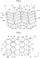
- FIG. 1 is a perspective view showing a manufacturing process of a core material which becomes the core layer. Note that a manufacturing method of this core material is described in detail in WO 2006/053407 A , which is incorporated herein by reference.
- a flat material sheet is thermoformed by a roller (not shown) having a predetermined die to be plastically deformed substantially without cutting the sheet, so that a core material 1 in the figure is formed.
- the material of the core material 1 to be used can include, for example, a thermoplastic resin such as polypropylene (PP), polyethylene (PE), polyethylene terephthalate (PET), a composite material with fibers, paper, and metal, but it is not limited to these.
- a thermoplastic resin is preferable.
- the thickness of the material sheet is preferably in the range of 0.05 mm to 0.50 mm, for example, but it is not limited to this, and the thickness of the core material 1 after thermoforming is substantially the same.
- the core material 1 has a three-dimensional structure in which ridge portions 11 and valley portions 12 are alternately arranged in a width direction X orthogonal to a manufacturing direction Y.
- the ridge portion 11 is configured with two side surfaces 13 and a top surface 17 between them
- the valley portion 12 is configured with two side surfaces 13 shared with the adjacent ridge portions 11 and a bottom surface 14 between them.
- the shape of the ridge portion 11 is a trapezoid as shown in FIG. 2 , but the present invention is not limited to this.
- shapes may be curved shapes such as sine curves or bow shapes.
- the core material 1 includes the three-dimensional structure continuously in the manufacturing direction Y. That is, as shown in FIG. 1 , a plurality of ridge portions 11a, 11b, 11c, and 11d are continuously formed in the manufacturing direction Y.
- the valley portions 12 are also formed continuously.
- the connection between the ridge portions 11 and the connection between the valley portions 12 are made by alternately repeating two types of connection methods.
- the first connection method is such that, as shown in FIG. 1 , on a first folding line X1 in the width direction, top surfaces 17b and 17c of two adjacent ridge portions 11b and 11c are connected, via trapezoidal-shaped ridge portion connecting surfaces 15b and 15c, respectively.
- the ridge portion connecting surface 15 is formed at a right angle to the top surface 17.
- the bottom surfaces 14b and 14c of two adjacent valley portions are directly connected.
- the second connection method is such that, as shown in FIG.
- valley portion connecting surface 16 is formed at a right angle to the bottom surface 14.
- top surfaces 12a and 12b (or 12c and 12d) of two adjacent ridge portions are directly connected.
- the core material 1 has a plurality of three-dimensional structures (the ridge portions 11 and the valley portions 12) connected via the connection regions (the ridge portion connecting surfaces 15 and the valley portion connecting surfaces 16), and has the connection region folded to form a core layer of the sound-absorbing material for a vehicle, of the present invention.
- the core material 1 is mountain-folded along the first folding line X1 such that the bottom surfaces 14b and 14c of two adjacent valley portions contact back-to-back with each other, and the angle formed by the ridge portion connecting surfaces 15b and 15c of two adjacent ridge portions increases to 180 degrees.
- the core material 1 is valley-folded along the second folding line X2 such that top surfaces 17a and 17b (or 17c and 17d) of two adjacent ridge portions contact face to face with each other, and the angle between the valley portion connecting surfaces 16a and 16b (or 16c and 16d) of two adjacent valley portions increases to 180 degrees.
- the core layer 10 includes substantially hexagonal tubular cells 20 arranged in a plurality of rows, and has cells 20A, 20C and 20E formed out of two adjacent ridge portions and cells 20B and 20D formed out of two adjacent valley portions, each arranged in every other row.
- a broken line 18 in FIG. 3 is the surface that has been the back surface of the core material, and generally indicates the inner wall of the cell 20 having the substantially hexagonal tubular shape.
- the cells 20A, 20C, and 20E formed from the ridge portions includes six cell side walls each forming the substantially hexagonal tubular shape. Each of these cell side walls is formed out of the two top surfaces 17 and the four side surfaces 13 of the cell material. Furthermore, these cells 20A, 20C, and 20E include substantially hexagonal tubular-shaped closed surfaces 21A, 21C, and 21E, respectively, to close the cell ends at the cell end on one surface 10a (front surface in FIG. 2 ) of the core layer 10. Each of these closed surfaces 21 on one side is formed out of two trapezoidal ridge portion connecting surfaces 15 in the cell material.
- these cells 20A, 20C, and 20E include open ends 22A, 22C, and 22E that are opened in the substantially hexagonal shape at the cell ends on the other surface 10b which is at the opposite side of the core layer 10.
- the open ends 22A, 22C, and 22E allow the respective internal spaces of the cells 20A, 20C, and 20E to be in communication with the outside.
- the cells 20B and 20D formed from the valley portions also includes six cell side walls each forming the substantially hexagonal tubular shape. Each of these cell side walls is formed from two bottom surfaces 14 and four side surfaces 13 of the cell material. Furthermore, these cells 20B and 20D include open ends 22B and 22D that are opened in the substantially hexagonal shape at the cell ends on the one surface 10a of the core layer 10. The open ends 22B and 22D allow the respective internal spaces of the cells 20B and 20D to be in communication with the outside. Furthermore, these cells 20B and 20D include substantially hexagonal tubular-shaped closed surfaces 21B and 21D that close the cell ends, respectively, at the cell end on the other surface 10b, which is at the opposite side of the core layer 10. Each of these closed surfaces 21 on the other side is formed out of the two trapezoidal valley portion connecting surfaces 16 in the cell material.
- the core layer 10 has the one-side closed surfaces 21A, 21C, and 21E formed out of the ridge portions of the cell material in every other row at the cell end on one surface 10a, and has the other-side closed surfaces 21B and 21D formed out of valley portions of the cell material in the different cell rows from the above at the cell end on the other surface 10b.
- both the closed surface 21 on one side and the closed surface 21 on the other side perform substantially the same function.
- the thickness of the entire core layer 10 varies depending on which component of the vehicle a multilayered structure is used for, so it is not limited to the following. However, it is preferably in the range of 3 mm to 25 mm, and is more preferably in the range of 5 mm to 20 mm from the viewpoint of controlling the peak of the sound absorption coefficient by the airflow-blocking resin film layer, to be described below, the sound absorption performance of the core layer 10 itself, and the strength and weight of the core layer 10.
- the basis weight (weight per unit area) of the core layer 10 varies depending on which component of the vehicle the multilayered structure is used for, so it is not limited to the following. However, it is preferably in the range of 400 g/m 2 to 4000 g/m 2 , and is more preferably in the range of 500 g/m 2 to 3000 g/m 2 . As the thickness of the core layer 10 is greater and the basis weight is greater, the strength of the core layer 10 tends to be higher, and the frequency at which the sound absorption coefficient is at the peak tends to be controllable at lower frequencies, in general.
- the basis weight of the core layer 10 can be adjusted by the type of material of the core layer 10, the thickness of the entire core layer 10 or the wall thickness of the cell 20 (thickness of the material sheet) as well as the pitches Pcx and Pcy between the cells 20 of the core layer 10 (distance between the central axes of the cells).
- the pitch Pcy between the cells 20 be in the range of 3 mm to 15 mm in the direction in which the cells 20 are adjacent to each other to form a row, which is the core manufacturing direction Y, and it is more preferable that the pitch Pcy be in the range of 4 mm to 10 mm.
- a sound-absorbing material for a vehicle includes a core layer 10 described above, an airflow-blocking resin film layer 40 provided on one surface thereof, and a nonwoven fabric layer 30 being provided on the resin film layer 40 and serving as an inner surface layer.
- the material of the airflow-blocking resin film layer 40 to be used may be, for example, resin films such as polypropylene (PP), polyethylene (PE), polyethylene terephthalate (PET), and polyamide (PA), but it is not limited to these.
- the airflow-blocking resin film layer 40 may have a structure in which a plurality of layers of these different types of resins are laminated, or may have a structure in which a plurality of layers of materials, each having different Young's modulus, are laminated even if they are of the same type of resin.
- the Young's modulus E of the airflow-blocking resin film layer 40 is not limited to the following because it depends on a ratio with a surface density E to be described below in detail, but it is lower than those to be used for general vehicle components, and for example, the upper limit thereof is preferably 1700 MPa or less, more preferably 1600 MPa or less, and still more preferably 1500 MPa or less.
- the lower limit of the Young's modulus is preferably 200 MPa or more, and more preferably 300 MPa or more, but it is not limited to these.
- the values of the Young's modulus in the direction in which the molten resin of the film flows (MD) and the Young's modulus in the direction perpendicular thereto (TD) differ depending on the type of resin and/or the manufacturing method of the film, but the Young's modulus of the lower value is used in calculating an E/M of the present invention.
- the surface density (basis weight) of the airflow-blocking resin film layer 40 also depends on the total surface density E with the nonwoven fabric layer 30 to be described below, and it is not limited to the following, but the lower limit thereof is, for example, preferably 30 g/m 2 or more, more preferably 40 g/m 2 or more, and still more preferably 50 g/m 2 or more.
- the upper limit of the surface density is preferably 500 g/m 2 or less, more preferably 300 g/m 2 or less, and still more preferably 250 g/m 2 or less, but it is not limited to these.
- the thickness of the airflow-blocking resin film layer 40 is not limited to the following, but the lower limit thereof is, for example, preferably 0.02 mm or more, more preferably 0.03 mm or more, and still more preferably 0.05 mm or more.
- the upper limit of the thickness is preferably 0.8 mm or less, more preferably 0.7 mm or less, and still more preferably 0.6 mm or less, but it is not limited to these.
- the airflow-blocking resin film layer 40 may be adhered to the core layer 10 by heat-welding, or may be adhered thereto via an adhesive (not shown).
- the adhesive to be used is not particularly limited, but for example, it may be an epoxy-based or acrylic-based adhesive.
- the airflow-blocking resin film layer 40 may have a three-layer structure including a central layer and two adhesive layers located on both side surfaces thereof.
- the material of the adhesive layers is a material having a melting point lower than the melting point of the material used for the central layer.
- polyamide having a melting point of 190°C to 220°C is used for the central layer
- polyethylene having a melting point of 90°C to 130°C is used for the adhesive layer.
- the temperature at the time of heating when the airflow-blocking resin film layer 40 is adhered to the core layer 10 and the nonwoven fabric layer 30, and the temperature for thermoforming into a predetermined shape of the sound-absorbing material for a vehicle are set to about 150°C to 160°C.
- This configuration and process melts the adhesive layers to firmly adhere to the core layer 10 and the nonwoven fabric layer 30, while not melting the central layer, so that the Young's modulus of the airflow-blocking resin film layer 40 is not significantly changed. This makes it possible to obtain desired sound absorption performance of the sound-absorbing material for a vehicle.
- a resin having a melting point higher than that of polyethylene for the adhesive layer there may be mentioned polypropylene, other than polyamide.
- nonwoven fabric layer 30 it is preferable to use various nonwoven fabrics such as spunbonded, spunlace, and needle punched nonwoven fabrics using a resin such as polyethylene terephthalate (PET), polypropylene (PP), or polyethylene (PE), but it is not limited to these.
- a resin such as polyethylene terephthalate (PET), polypropylene (PP), or polyethylene (PE), but it is not limited to these.
- the surface density (basis weight) of the nonwoven fabric layer 30 is not limited to the following because it depends on the total surface density E with the airflow-blocking resin film layer 40, but the lower limit thereof is, for example, preferably 10 g/m 2 or more, more preferably 20 g/m 2 or more, and still more preferably 30 g/m 2 or more.
- the upper limit of the surface density is preferably 500 g/m 2 or less, more preferably 300 g/m 2 or less, and still more preferably 250 g/m 2 or less, but it is not limited to these.
- the Young's modulus of the airflow-blocking resin film layer 40 is defined as E
- the total surface density of the airflow-blocking resin film layer 40 and the nonwoven fabric layer 30 is defined as M.
- E/M values are set to the range of 0.5 to 21 to enable the peak of the sound absorption coefficient of the sound-absorbing material for a vehicle to be controlled into the frequency band of 500 Hz to 8000 Hz, which causes annoying noise in vehicles.
- the E/M value is preferably in the range of 0.5 to 8, and furthermore, when the peak of the sound absorption coefficient is to be provided in the band of 1000 Hz to 3000 Hz, the E/M value is more preferably in the range of 1.5 to 5.5.
- the E/M value is preferably in the range of 8 to 21, and furthermore, when the peak of the sound absorption coefficient is to be provided in the band of 5000 Hz to 6000 Hz, the value of E/M is preferably in the range of 11 to 14.
- an airflow-blocking resin film layer 40 is provided on at least one surface of the core layer 10 in which open ends and closed surfaces are arranged in every other row, and a nonwoven fabric layer 30 is further provided on the outside of the resin film layer 40.
- E/M which is the ratio of Young's modulus E of the airflow-blocking resin film layer 40 to the total surface density M of the airflow-blocking resin film layer 40 and the nonwoven fabric layer 30, is adjusted. This enables controlling the peak of the sound absorption coefficient of the sound-absorbing material for a vehicle in a desired frequency band.
- FIGs. 4 and 5 show a case in which the nonwoven fabric layer 30 is provided on the outside of the airflow-blocking resin film layer 40, the present invention is not limited to this.
- This configuration enables the peak of the sound absorption coefficient of the sound-absorbing material for a vehicle to be controlled in a desired frequency band, similarly to the above.
- a sound-absorbing material for a vehicle of a second embodiment includes: the core layer 10 described above; a first airflow-blocking resin film layer 40a provided on one surface thereof; a second airflow-blocking resin film layer 40b provided on the other surface thereof; and a first and a second nonwoven fabric layers 30a and 30b serving as an inner surface layer and an outer surface layer respectively and being provided on the respective airflow-blocking resin film layers.
- a first airflow-blocking resin film layer 40a provided on one surface thereof
- a second airflow-blocking resin film layer 40b provided on the other surface thereof
- a first and a second nonwoven fabric layers 30a and 30b serving as an inner surface layer and an outer surface layer respectively and being provided on the respective airflow-blocking resin film layers.
- Both the first and second airflow-blocking resin film layers 40a and 40b, and the first and second nonwoven fabric layers 30a and 30b, which are adhered on both side surfaces of the core layer 10, may have the same configuration (the material and thickness of the resin film, the manufacturing method and basis weight of nonwoven fabric, or the like), or may have different configurations on the opposite side surfaces thereof.
- the value of E/M which is the ratio of the Young's modulus E of the airflow-blocking resin film layer 40 to the total surface density M of the airflow-blocking resin film layer 40 and the nonwoven fabric layer 30, is adjusted separately on the first airflow-blocking resin film layer 40a side and the second airflow-blocking resin film layer 40b side. That is, the Young's modulus of the first airflow-blocking resin film layer 40a is defined as E 1 , and the total surface density of the first airflow-blocking resin film layer 40a and the first nonwoven fabric layer 30a is defined as M 1 , and E 1 /M 1 values are set in the range of 0.5 to 21.
- the Young's modulus of the second airflow-blocking resin film layer 40b is defined as E 2
- the total surface density of the second airflow-blocking resin film layer 40b and the second nonwoven fabric layer 30b is defined as M 2
- E 2 /M 2 values are set to the range of 0.5 to 21.
- the value of E 1 /M 1 and the value of E 2 /M 2 are preferably different, and the absolute value of the difference between E 1 /M 1 and E 2 /M 2 is preferably 0.8 or more, more preferably 2.0 or more, and still more preferably 3.0 or more.
- the upper limit of the absolute value of this difference is not particularly limited, but it is preferably 5 or less, for example.
- the sound-absorbing material for a vehicle is configured such that: the airflow-blocking resin film layer 40 and the nonwoven fabric layer 30 are provided on each of both surfaces of the core layer 10 in which the open ends and the closed surfaces are arranged in every other row; both the value of E 1 /M 1 on the first airflow-blocking resin film layer 40a side and the value of E 2 /M 2 on the second airflow-blocking resin film layer 40b side are set within the range of 0.5 to 21; and furthermore, the values are made different from each other within this range.
- This configuration makes it possible to obtain the sound-absorbing material for a vehicle with excellent sound absorption performance having two peaks of sound absorption coefficient in a frequency band of 500 Hz to 8000 Hz, which causes annoying noise in a vehicle.
- setting the absolute value of the difference between the values of E 1 /M 1 and E 2 /M 2 to 0.8 or more enables widening the frequency band of absorbing sound.
- the sound-absorbing material for a vehicle of a third embodiment includes: the core layer 10 described above; an airflow-blocking resin film layer 40 provided on one surface thereof; a resin film layer 50 having a plurality of apertures on the surface of the core layer 10 opposite to the airflow-blocking resin film layer 40; and a first and a second nonwoven fabric layers 30a and 30b serving as an inner surface layer and an outer surface layer respectively and being provided on the respective airflow-blocking resin film layers.
- the same configurations as those in the first and second embodiments are referred to by the same reference signs, and detailed descriptions thereof are omitted here.
- the resin film layer 50 having a plurality of apertures (hereinafter referred to as the apertured film layer 50) has a plurality of holes 55 passing through the layer.
- the holes 55 are opened in advance before the adhesion to the core layer 10, for example, by a hot needle or punching (punching using a male die and a female die).
- a hot needle or punching punching using a male die and a female die.
- the holes 55 do not have any particular limitation on their aperture pattern, but they are preferably arranged in a staggered arrangement or a lattice arrangement.
- the aperture rate of the apertured film layer 50 is not particularly limited, but it is preferably in the range of 0.2% to 5%.
- the diameter of the holes 55 is preferably in the range of 0.25 mm to 2.5 mm, and more preferably in the range of 0.3 mm to 2.0 mm.
- the pitches of the holes 55 of the apertured film layer 50 do not necessarily have to be the same as the pitches Pcx and Pcy of the cells 20 of the core layer 10 shown in FIG. 2 , and the holes 55 and the cells 20 do not necessarily have to be aligned when the apertured film layer 50 is adhered to the core layer 10. This is because the positions of the holes 55 of the apertured film layer 50 and the open ends 22 of the cells 20 of the core layer 10 randomly overlap with each other to enable appropriate communication between the inside and outside. It is preferable that the pitch of the holes 55 of the apertured film layer 50 be smaller than the pitch of the cells 20 of the core layer 10 at least in either an X direction or a Y direction.
- the same effect as in the first embodiment can be obtained.
- the aperture pattern preformed in the apertured film layer 50 can readily adjust and stably maintain the degree of blockage of the open ends 22 on at least one surface of the core layer 10. This enables controlling the peak of the sound absorption coefficient of the sound-absorbing material for a vehicle, and thus enables, together with the E/M value on the airflow-blocking resin film layer 40 side, more readily controlling the peak of the sound absorption coefficient of the sound-absorbing material for a vehicle in a desired frequency band.
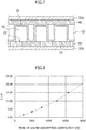
- Example 1 a sound-absorbing material for a vehicle, having a multilayer structure shown in FIGs. 4 and 5 , was produced.
- a three-layered airflow-blocking resin film with a thickness of 50 ⁇ m (the material being polyethylene/polyamide/polyethylene, the Young's modulus of the film being 300 MPa) was adhered to one surface of the core layer having the structure of FIGs. 1 to 3 .
- a spunbonded nonwoven fabric (the material being polyethylene terephthalate, the basis weight being 250 g/m 2 ) was adhered on the airflow-blocking resin film, as an inner surface layer.
- the total surface density of the airflow-blocking resin film and the nonwoven fabric was 180 g/m 2 .
- this multilayered structure was heated and pressed to obtain a sound-absorbing material for a vehicle in which the layers were adhered.
- a cylindrical sample having a diameter of about 29 mm was taken from the sound-absorbing material for a vehicle of Example 1 according to a method conforming to ISO10534-2 (JIS A 1405), and then the normal incident sound absorption coefficients at frequencies of 500 Hz to 6300 Hz of this sample were measured. As a result, the peak frequency of the sound absorption coefficient was 1000 Hz.
- Example 1 In the same manner as in Example 1, as shown in Table 1 below, sound-absorbing materials for a vehicle of Examples 2 to 6, which vary in the materials, the basis weights, the thicknesses, and the like of the nonwoven fabrics and the airflow-blocking resin films, were produced, and the sound absorption performances thereof were measured. Table 1 and FIG. 8 show the results including Example 1.
- the core layer used was made of a polypropylene resin and had a thickness of about 20 mm or less and a pitch Pcy between cells of about 10 mm or less.
- E/M which is the ratio of the Young's modulus E of the airflow-blocking resin film layer to the surface density M of the layer structure on the core layer, the higher the peak frequency of the sound absorption coefficient of the sound-absorbing material for a vehicle.
- E/M the ratio of the Young's modulus E of the airflow-blocking resin film layer to the surface density M of the layer structure on the core layer
- Examples 1 to 6 indicate that, with E/M values being set to the range of 0.5 to 21, it is possible to produce sound-absorbing material for vehicles having desired sound absorption performance having a peak of sound absorption coefficient in the frequency band of 500 Hz to 8000 Hz, which causes annoying noise in vehicles.
- the sound-absorbing material for a vehicle of the present invention adhering an airflow-blocking resin film layer enables controlling the peak of the sound absorption coefficient into the frequency band of 500 Hz to 8000 Hz while maintaining a low weight and a high rigidity. More specifically, the sound-absorbing material for a vehicle of the present invention is useful for sound-absorbing cover components of noise generating sources such as floor carpets, floor spacers, trunk trims, trunk floors, dash insulators, and undercovers.
Landscapes
- Engineering & Computer Science (AREA)
- Mechanical Engineering (AREA)
- Physics & Mathematics (AREA)
- Acoustics & Sound (AREA)
- Multimedia (AREA)
- Textile Engineering (AREA)
- Vehicle Interior And Exterior Ornaments, Soundproofing, And Insulation (AREA)
- Laminated Bodies (AREA)
- Soundproofing, Sound Blocking, And Sound Damping (AREA)
Abstract
Description
- The present invention relates to a sound-absorbing material for vehicles.
- A typical structure of a vehicle has an engine compartment provided at the front, a trunk compartment provided at the rear, and a passenger compartment provided in the middle thereof. The passenger compartment is provided with seats such as a driver's seat, a front passenger seat, and a rear seat. The passenger compartment has a dash insulator, a floor carpet, a floor spacer, a trunk trim, and a trunk floor installed so that they cover the outside of the vehicle interior. These components are formed in an uneven shape according to shapes of vehicle bodies or designs of components. Furthermore, the exterior under a vehicle body has a front fender liner, a rear fender liner, and an undercover which is formed in an uneven shape for controlling air flow, installed thereon. For many of these components, a thermoplastic resin is used as a material, and each of the materials is heated and press-molded by a die having the shape of the component to be finished into an uneven-shaped component having a plurality of portions with different thicknesses.
- As a recent trend in vehicle development, the quietness in the interior of a vehicle is emphasized. Noise transmitted to the interior of a vehicle includes noise from the windows, noise from the tires, noise from under the vehicle body, noise from engine sounds, and noise from motor sounds. It is said that particularly noise of frequencies of 500 Hz to 4000 Hz is annoying to drivers and passengers. In addition, it is said that, in electric vehicles, even frequencies of 4000 to 8000 Hz, to which annoyance has not been felt conventionally, would cause annoyance to drivers and passengers because electric vehicles have no engine. Therefore, the interior and exterior components of vehicles are required to have a function of absorbing noise in these frequency bands. On the other hand, it is also important to reduce fuel consumption, and it is also required to reduce weight of interior and exterior components of vehicles.
- In addition,
JP 4539294 B - Patent Document 1:
JP 4539294 B - The frequency selection plate of
JP 4539294 B - Therefore, it is an object of the present invention to provide a sound-absorbing material for a vehicle, capable of stably yielding desired sound absorption performance while reducing the weight of the sound-absorbing material for a vehicle.
- In order to achieve the object, the present invention provides a sound-absorbing material for a vehicle, having a multilayer structure, the material including: a core layer having tubular cells, the tubular cells being arranged in a plurality of rows; and a first airflow-blocking resin film layer adhered to one surface of the core layer, wherein a relationship between a Young's modulus E1 (MPa) of the first airflow-blocking resin film layer and a surface density M1 (g/m2) of a layer structure on the first airflow-blocking resin film layer side with respect to the core layer is 0.5 < E1/M1 < 21.
- The tubular cell may have a polygonal tubular shape such as a substantially quadrangular tubular shape or a substantially hexagonal tubular shape, or may have a curved tubular shape such as a substantially circular tubular shape or a substantially elliptical tubular shape. It is preferable that each of the cells in the core layer have a closed surface at one end and an open end at another end, the open ends of the cells allow an internal space of the cell to be in communication with an outside, and the open ends of the cells be arranged on both sides of the core layer such that rows of the open ends of the cells are in every other row. The open end, the one-side closed surface, and the other-side closed surface may have a polygonal shape such as a substantially quadrangular shape or a substantially hexagonal shape, or may have a curved shape such as a substantially circular shape or a substantially elliptical shape, according to the shape of the cell.
- The first airflow-blocking resin film layer may have a structure in which a plurality of materials having different Young's modulus are laminated. The Young's modulus E1 in this case is the Young's modulus of the entire first airflow-blocking resin film layer. In addition, the sound-absorbing material for a vehicle, of the present invention, may further include an inner surface layer on the surface of the first airflow-blocking resin film layer opposite to the core layer. The surface density M1 in this case is the total surface density (mass per unit area) of the first airflow-blocking resin film layer and the inner surface layer. The inner surface layer is a layer of the surface facing the vehicle inner side, and may be, for example, a layer configured with fiber such as nonwoven fabric, plain needle punched fabric, or velour, a layer configured with a foamed resin such as urethane foam, polyethylene foam or nylon foam, or a layer in which these are combined.
- The sound-absorbing material for a vehicle of the present invention may further include a second airflow-blocking resin film layer adhered to a surface of the core layer, the surface being opposite to the surface to which the first airflow-blocking resin film layer is adhered. In this case, a relationship between a Young's modulus E2 (MPa) of the second airflow-blocking resin film layer and a surface density M2 (g/m2) of a layer structure on the second airflow-blocking resin film layer side with respect to the core layer may satisfy 0.5 < E2/M2 < 21 or need not satisfy it. In addition, the absolute value of the difference between E1/M1 and E2/M2 may be 0.8 or more. Furthermore, the sound-absorbing material for a vehicle of the present invention may further include an outer surface layer on the surface of the second airflow-blocking resin film layer opposite to the core layer. The surface density M2 in this case is the total surface density of the second airflow-blocking resin film layer and the outer surface layer. The outer surface layer is a layer of the surface facing the vehicle outer side, and may be, for example, a layer configured with fiber such as nonwoven fabric, plain needle punched fabric, or velour, a layer configured with a foamed resin such as urethane foam, polyethylene foam or nylon foam, or a layer in which these are combined.
- Alternatively, the sound-absorbing material for a vehicle, of the present invention, may further include a resin film layer having a plurality of apertures, the resin film layer being adhered to a surface of the core layer, the surface being opposite to the surface to which the first airflow-blocking resin film layer is adhered.
- As described above, the sound-absorbing material for a vehicle, according to the present invention, includes: a core layer in which tubular cells are arranged in a plurality of rows; and a first airflow-blocking resin film layer adhered to one surface of the core layer. The sound-absorbing material for a vehicle has a configuration such that a relationship between a Young's modulus E1 of the first airflow-blocking resin film layer and a surface density M1 of a layer structure on the first airflow-blocking resin film layer side with respect to the core layer is 0.5 < E1/M1 < 21. With this configuration, when the airflow-blocking resin film layer has a Young's modulus E1 significantly smaller than typical ones with respect to the surface density M1, use of an airflow-blocking resin film layer, which generally is not considered to contribute to sound absorption, also contributes to sound absorption from the relationship with the predetermined structure of the core layer. This makes it possible to obtain desired sound absorption performance having a peak of sound absorption coefficient in the frequency band of 500 Hz to 8000 Hz, which causes annoying noise in vehicles. As described above, the predetermined structure of the core layer and the first airflow-blocking resin film layer enables high rigidity even with weight reduction of the vehicle component. The structure also enables exhibiting the desired sound absorption performance without using a member having a plurality of apertures, which can eliminate accumulation of dirt in the apertures to stably obtain the desired sound absorption performance.
- The configuration, in which the first airflow-blocking resin film layer has a structure in which a plurality of materials having different Young's modulus are laminated, facilitates the design of the Young's modulus E1 and the surface density M1. This can facilitate the control of the peak of the sound absorption coefficient.
- The configuration, in which an inner surface layer is further provided on the surface of the first airflow-blocking resin film layer opposite to the core layer, makes it possible to protect the first airflow-blocking resin film layer having a Young's modulus less than general ones, and to stably obtain the desired sound absorption performance.
- The configuration is such that: a second airflow-blocking resin film layer is adhered to the surface of the core layer opposite to the surface to which the first airflow-blocking resin film layer is adhered; and the absolute value of the difference between E2/M2 and E1/M1 is 0.8 or more, where E2 is the Young's modulus of the second airflow-blocking resin film layer, and M2 is the surface density of the layer structure on the second airflow-blocking resin film layer side with respect to the core layer. This configuration makes it possible to obtain a sound-absorbing material for a vehicle, having two peaks of sound absorption coefficient in a frequency band of 500 Hz to 8000 Hz, which causes annoying noise in a vehicle, and thus, has excellent sound absorption performance with a wide frequency band of absorbing sound.
- The sound-absorbing material for a vehicle may further include a resin film layer having a plurality of apertures, the resin film layer adhered to the surface of the core layer opposite to the surface to which the first airflow-blocking resin film layer is adhered. An aperture pattern preformed on the resin film layer having a plurality of apertures makes it possible to readily adjust and stably maintain the degree of blockage of the open end on at least one surface of the core layer. This enables controlling the peak of the sound absorption coefficient of the sound-absorbing material for a vehicle, and thus enables, together with the E/M values, more readily controlling the peak of the sound absorption coefficient of the sound-absorbing material for a vehicle into a desired frequency band.
- A sound-absorbing material for a vehicle has a configuration such that: each of the cells in the core layer has a closed surface at one end and an open end at another end; the open ends of the cells allow an internal space of the cell to be in communication with an outside; and the open ends of the cells are arranged on both sides of the core layer such that rows of the open ends of the cells are in every other row. With this configuration, the closed surface of the cell in the core layer ensures that it serves as a surface for adhering the first airflow-blocking resin film layer and the core layer, and the closed surface of the cell is arranged in every other row. This can improve adhesiveness between the first airflow-blocking resin film layer and the core layer.
-
-
FIG. 1 is a perspective view showing a manufacturing process of a core material used for a core layer in a sound-absorbing material for a vehicle according to the present invention. -
FIG. 2 is a schematic plan view showing a core layer in a sound-absorbing material for a vehicle according to the present invention. -
FIG. 3 is a schematic cross-sectional view showing the core layer ofFIG. 2 along line III-III. -
FIG. 4 is an exploded perspective view showing an embodiment of a sound-absorbing material for a vehicle according to the present invention. -
FIG. 5 is a schematic cross-sectional view of the embodiment of the sound-absorbing material for a vehicle shown inFIG. 4 . -
FIG. 6 is an exploded perspective view showing another embodiment of a sound-absorbing material for a vehicle, according to the present invention. -
FIG. 7 is a schematic cross-sectional view showing another embodiment of a sound-absorbing material for a vehicle, according to the present invention. -
FIG. 8 is a graph showing a relationship between E1/M1 and sound absorption peak frequencies in examples of a sound-absorbing material for a vehicle, according to the present invention. - An embodiment of a sound-absorbing material for a vehicle, according to the present invention, is described below with reference to the accompanying drawings. Note that the drawings are not intended to be drawn to scale unless otherwise specified.
- First, a core layer common to each embodiment of the sound-absorbing material for a vehicle, according to the present invention, is described below.
FIG. 1 is a perspective view showing a manufacturing process of a core material which becomes the core layer. Note that a manufacturing method of this core material is described in detail inWO 2006/053407 A , which is incorporated herein by reference. - As shown in
FIG. 1 , a flat material sheet is thermoformed by a roller (not shown) having a predetermined die to be plastically deformed substantially without cutting the sheet, so that acore material 1 in the figure is formed. The material of thecore material 1 to be used can include, for example, a thermoplastic resin such as polypropylene (PP), polyethylene (PE), polyethylene terephthalate (PET), a composite material with fibers, paper, and metal, but it is not limited to these. In particular, a thermoplastic resin is preferable. In this embodiment, a case in which a thermoplastic resin is used is described below. The thickness of the material sheet is preferably in the range of 0.05 mm to 0.50 mm, for example, but it is not limited to this, and the thickness of thecore material 1 after thermoforming is substantially the same. - The
core material 1 has a three-dimensional structure in which ridge portions 11 and valley portions 12 are alternately arranged in a width direction X orthogonal to a manufacturing direction Y. The ridge portion 11 is configured with twoside surfaces 13 and atop surface 17 between them, and the valley portion 12 is configured with twoside surfaces 13 shared with the adjacent ridge portions 11 and abottom surface 14 between them. In this embodiment, a case is described in which the shape of the ridge portion 11 is a trapezoid as shown inFIG. 2 , but the present invention is not limited to this. In addition to polygons such as triangles or rectangles, shapes may be curved shapes such as sine curves or bow shapes. - The
core material 1 includes the three-dimensional structure continuously in the manufacturing direction Y. That is, as shown inFIG. 1 , a plurality ofridge portions - The first connection method is such that, as shown in
FIG. 1 , on a first folding line X1 in the width direction,top surfaces adjacent ridge portions portion connecting surfaces portion connecting surface 15 is formed at a right angle to thetop surface 17. On the first folding line X1 in the width direction, the bottom surfaces 14b and 14c of two adjacent valley portions are directly connected. The second connection method is such that, as shown inFIG. 2 , on a second folding line X2 in the width direction, bottom surfaces 14a and 14b (or 14c and 14d) of two adjacent valley portions are connected, via trapezoidal-shaped valleyportion connecting surfaces portion connecting surface 16 is formed at a right angle to thebottom surface 14. On the second folding line X2 in the width direction,top surfaces - Thus, the
core material 1 has a plurality of three-dimensional structures (the ridge portions 11 and the valley portions 12) connected via the connection regions (the ridgeportion connecting surfaces 15 and the valley portion connecting surfaces 16), and has the connection region folded to form a core layer of the sound-absorbing material for a vehicle, of the present invention. Specifically, thecore material 1 is mountain-folded along the first folding line X1 such that the bottom surfaces 14b and 14c of two adjacent valley portions contact back-to-back with each other, and the angle formed by the ridgeportion connecting surfaces core material 1 is valley-folded along the second folding line X2 such thattop surfaces portion connecting surfaces core layer 10 of the sound-absorbing material for a vehicle, of the present invention, obtained by folding thecore material 1 in this manner, is shown inFIGs. 2 and3 . - As shown in
FIGs. 2 and3 , thecore layer 10 includes substantially hexagonaltubular cells 20 arranged in a plurality of rows, and hascells cells broken line 18 inFIG. 3 is the surface that has been the back surface of the core material, and generally indicates the inner wall of thecell 20 having the substantially hexagonal tubular shape. - The
cells top surfaces 17 and the fourside surfaces 13 of the cell material. Furthermore, thesecells closed surfaces surface 10a (front surface inFIG. 2 ) of thecore layer 10. Each of theseclosed surfaces 21 on one side is formed out of two trapezoidal ridgeportion connecting surfaces 15 in the cell material. Furthermore, thesecells other surface 10b which is at the opposite side of thecore layer 10. The open ends 22A, 22C, and 22E allow the respective internal spaces of thecells - The
cells bottom surfaces 14 and fourside surfaces 13 of the cell material. Furthermore, thesecells surface 10a of thecore layer 10. The open ends 22B and 22D allow the respective internal spaces of thecells cells closed surfaces other surface 10b, which is at the opposite side of thecore layer 10. Each of theseclosed surfaces 21 on the other side is formed out of the two trapezoidal valleyportion connecting surfaces 16 in the cell material. - In this way, the
core layer 10 has the one-side closed surfaces 21A, 21C, and 21E formed out of the ridge portions of the cell material in every other row at the cell end on onesurface 10a, and has the other-side closedsurfaces other surface 10b. However, unless otherwise stated, both theclosed surface 21 on one side and theclosed surface 21 on the other side perform substantially the same function. - The thickness of the
entire core layer 10 varies depending on which component of the vehicle a multilayered structure is used for, so it is not limited to the following. However, it is preferably in the range of 3 mm to 25 mm, and is more preferably in the range of 5 mm to 20 mm from the viewpoint of controlling the peak of the sound absorption coefficient by the airflow-blocking resin film layer, to be described below, the sound absorption performance of thecore layer 10 itself, and the strength and weight of thecore layer 10. - The basis weight (weight per unit area) of the
core layer 10 varies depending on which component of the vehicle the multilayered structure is used for, so it is not limited to the following. However, it is preferably in the range of 400 g/m2 to 4000 g/m2, and is more preferably in the range of 500 g/m2 to 3000 g/m2. As the thickness of thecore layer 10 is greater and the basis weight is greater, the strength of thecore layer 10 tends to be higher, and the frequency at which the sound absorption coefficient is at the peak tends to be controllable at lower frequencies, in general. - The basis weight of the
core layer 10 can be adjusted by the type of material of thecore layer 10, the thickness of theentire core layer 10 or the wall thickness of the cell 20 (thickness of the material sheet) as well as the pitches Pcx and Pcy between thecells 20 of the core layer 10 (distance between the central axes of the cells). In order to set the basis weight of thecore layer 10 within the above range, for example, it is preferable that the pitch Pcy between thecells 20 be in the range of 3 mm to 15 mm in the direction in which thecells 20 are adjacent to each other to form a row, which is the core manufacturing direction Y, and it is more preferable that the pitch Pcy be in the range of 4 mm to 10 mm. - Next, individual embodiments of sound-absorbing materials for a vehicle, according to the present invention, are described below using the
core layer 10 described above. - As shown in
FIGs. 4 and5 , a sound-absorbing material for a vehicle, of a first embodiment, includes acore layer 10 described above, an airflow-blockingresin film layer 40 provided on one surface thereof, and anonwoven fabric layer 30 being provided on theresin film layer 40 and serving as an inner surface layer. - The material of the airflow-blocking
resin film layer 40 to be used may be, for example, resin films such as polypropylene (PP), polyethylene (PE), polyethylene terephthalate (PET), and polyamide (PA), but it is not limited to these. In addition, the airflow-blockingresin film layer 40 may have a structure in which a plurality of layers of these different types of resins are laminated, or may have a structure in which a plurality of layers of materials, each having different Young's modulus, are laminated even if they are of the same type of resin. - The Young's modulus E of the airflow-blocking
resin film layer 40 is not limited to the following because it depends on a ratio with a surface density E to be described below in detail, but it is lower than those to be used for general vehicle components, and for example, the upper limit thereof is preferably 1700 MPa or less, more preferably 1600 MPa or less, and still more preferably 1500 MPa or less. In addition, the lower limit of the Young's modulus is preferably 200 MPa or more, and more preferably 300 MPa or more, but it is not limited to these. Note that the values of the Young's modulus in the direction in which the molten resin of the film flows (MD) and the Young's modulus in the direction perpendicular thereto (TD) differ depending on the type of resin and/or the manufacturing method of the film, but the Young's modulus of the lower value is used in calculating an E/M of the present invention. - The surface density (basis weight) of the airflow-blocking
resin film layer 40 also depends on the total surface density E with thenonwoven fabric layer 30 to be described below, and it is not limited to the following, but the lower limit thereof is, for example, preferably 30 g/m2 or more, more preferably 40 g/m2 or more, and still more preferably 50 g/m2 or more. In addition, the upper limit of the surface density is preferably 500 g/m2 or less, more preferably 300 g/m2 or less, and still more preferably 250 g/m2 or less, but it is not limited to these. - The thickness of the airflow-blocking
resin film layer 40 is not limited to the following, but the lower limit thereof is, for example, preferably 0.02 mm or more, more preferably 0.03 mm or more, and still more preferably 0.05 mm or more. In addition, the upper limit of the thickness is preferably 0.8 mm or less, more preferably 0.7 mm or less, and still more preferably 0.6 mm or less, but it is not limited to these. - The airflow-blocking
resin film layer 40 may be adhered to thecore layer 10 by heat-welding, or may be adhered thereto via an adhesive (not shown). The adhesive to be used is not particularly limited, but for example, it may be an epoxy-based or acrylic-based adhesive. In addition, in order to heat-weld the airflow-blockingresin film layer 40 with thecore layer 10 and thenonwoven fabric layer 30, for example, the airflow-blockingresin film layer 40 may have a three-layer structure including a central layer and two adhesive layers located on both side surfaces thereof. In this case, the material of the adhesive layers is a material having a melting point lower than the melting point of the material used for the central layer. For example, polyamide having a melting point of 190°C to 220°C is used for the central layer, and polyethylene having a melting point of 90°C to 130°C is used for the adhesive layer. Then, the temperature at the time of heating when the airflow-blockingresin film layer 40 is adhered to thecore layer 10 and thenonwoven fabric layer 30, and the temperature for thermoforming into a predetermined shape of the sound-absorbing material for a vehicle are set to about 150°C to 160°C. This configuration and process melts the adhesive layers to firmly adhere to thecore layer 10 and thenonwoven fabric layer 30, while not melting the central layer, so that the Young's modulus of the airflow-blockingresin film layer 40 is not significantly changed. This makes it possible to obtain desired sound absorption performance of the sound-absorbing material for a vehicle. As a resin having a melting point higher than that of polyethylene for the adhesive layer, there may be mentioned polypropylene, other than polyamide. - For the
nonwoven fabric layer 30, it is preferable to use various nonwoven fabrics such as spunbonded, spunlace, and needle punched nonwoven fabrics using a resin such as polyethylene terephthalate (PET), polypropylene (PP), or polyethylene (PE), but it is not limited to these. - The surface density (basis weight) of the
nonwoven fabric layer 30 is not limited to the following because it depends on the total surface density E with the airflow-blockingresin film layer 40, but the lower limit thereof is, for example, preferably 10 g/m2 or more, more preferably 20 g/m2 or more, and still more preferably 30 g/m2 or more. In addition, the upper limit of the surface density is preferably 500 g/m2 or less, more preferably 300 g/m2 or less, and still more preferably 250 g/m2 or less, but it is not limited to these. - In this embodiment, the Young's modulus of the airflow-blocking
resin film layer 40 is defined as E, and the total surface density of the airflow-blockingresin film layer 40 and thenonwoven fabric layer 30 is defined as M. Here, E/M values are set to the range of 0.5 to 21 to enable the peak of the sound absorption coefficient of the sound-absorbing material for a vehicle to be controlled into the frequency band of 500 Hz to 8000 Hz, which causes annoying noise in vehicles. Outside of this frequency band, when the peak of the sound absorption coefficient is to be provided in the band of 500 Hz to 4000 Hz, the E/M value is preferably in the range of 0.5 to 8, and furthermore, when the peak of the sound absorption coefficient is to be provided in the band of 1000 Hz to 3000 Hz, the E/M value is more preferably in the range of 1.5 to 5.5. In addition, when the peak of the sound absorption coefficient is to be provided in the band of 4000 Hz to 8000 Hz, the E/M value is preferably in the range of 8 to 21, and furthermore, when the peak of the sound absorption coefficient is to be provided in the band of 5000 Hz to 6000 Hz, the value of E/M is preferably in the range of 11 to 14. - As described above, according to the first embodiment, an airflow-blocking
resin film layer 40 is provided on at least one surface of thecore layer 10 in which open ends and closed surfaces are arranged in every other row, and anonwoven fabric layer 30 is further provided on the outside of theresin film layer 40. This configuration enables high rigidity even with weight reduction of the sound-absorbing material for a vehicle. At the same time, the value of E/M, which is the ratio of Young's modulus E of the airflow-blockingresin film layer 40 to the total surface density M of the airflow-blockingresin film layer 40 and thenonwoven fabric layer 30, is adjusted. This enables controlling the peak of the sound absorption coefficient of the sound-absorbing material for a vehicle in a desired frequency band. - Note that, although
FIGs. 4 and5 show a case in which thenonwoven fabric layer 30 is provided on the outside of the airflow-blockingresin film layer 40, the present invention is not limited to this. There may be a configuration such that nononwoven fabric layer 30 is provided, and the Young's modulus E of the airflow-blockingresin film layer 40 and the surface density M of only the airflow-blockingresin film layer 40 is adjusted. This configuration enables the peak of the sound absorption coefficient of the sound-absorbing material for a vehicle to be controlled in a desired frequency band, similarly to the above. - As shown in
FIG. 6 , a sound-absorbing material for a vehicle of a second embodiment includes: thecore layer 10 described above; a first airflow-blockingresin film layer 40a provided on one surface thereof; a second airflow-blockingresin film layer 40b provided on the other surface thereof; and a first and a secondnonwoven fabric layers - Both the first and second airflow-blocking resin film layers 40a and 40b, and the first and second
nonwoven fabric layers core layer 10, may have the same configuration (the material and thickness of the resin film, the manufacturing method and basis weight of nonwoven fabric, or the like), or may have different configurations on the opposite side surfaces thereof. - Thus, when the airflow-blocking
resin film layer 40 is provided on both sides of thecore layer 10, the value of E/M, which is the ratio of the Young's modulus E of the airflow-blockingresin film layer 40 to the total surface density M of the airflow-blockingresin film layer 40 and thenonwoven fabric layer 30, is adjusted separately on the first airflow-blockingresin film layer 40a side and the second airflow-blockingresin film layer 40b side. That is, the Young's modulus of the first airflow-blockingresin film layer 40a is defined as E1, and the total surface density of the first airflow-blockingresin film layer 40a and the firstnonwoven fabric layer 30a is defined as M1, and E1/M1 values are set in the range of 0.5 to 21. In addition, the Young's modulus of the second airflow-blockingresin film layer 40b is defined as E2, and the total surface density of the second airflow-blockingresin film layer 40b and the secondnonwoven fabric layer 30b is defined as M2, and E2/M2 values are set to the range of 0.5 to 21. The value of E1/M1 and the value of E2/M2 are preferably different, and the absolute value of the difference between E1/M1 and E2/M2 is preferably 0.8 or more, more preferably 2.0 or more, and still more preferably 3.0 or more. Note that the upper limit of the absolute value of this difference is not particularly limited, but it is preferably 5 or less, for example. - According to the second embodiment, the sound-absorbing material for a vehicle is configured such that: the airflow-blocking
resin film layer 40 and thenonwoven fabric layer 30 are provided on each of both surfaces of thecore layer 10 in which the open ends and the closed surfaces are arranged in every other row; both the value of E1/M1 on the first airflow-blockingresin film layer 40a side and the value of E2/M2 on the second airflow-blockingresin film layer 40b side are set within the range of 0.5 to 21; and furthermore, the values are made different from each other within this range. This configuration makes it possible to obtain the sound-absorbing material for a vehicle with excellent sound absorption performance having two peaks of sound absorption coefficient in a frequency band of 500 Hz to 8000 Hz, which causes annoying noise in a vehicle. In particular, setting the absolute value of the difference between the values of E1/M1 and E2/M2 to 0.8 or more enables widening the frequency band of absorbing sound. - As shown in
FIG. 7 , the sound-absorbing material for a vehicle of a third embodiment includes: thecore layer 10 described above; an airflow-blockingresin film layer 40 provided on one surface thereof; aresin film layer 50 having a plurality of apertures on the surface of thecore layer 10 opposite to the airflow-blockingresin film layer 40; and a first and a secondnonwoven fabric layers - The
resin film layer 50 having a plurality of apertures (hereinafter referred to as the apertured film layer 50) has a plurality ofholes 55 passing through the layer. Theholes 55 are opened in advance before the adhesion to thecore layer 10, for example, by a hot needle or punching (punching using a male die and a female die). In order to prevent the holes from being closed, it is preferable to have a hole shape in which burrs of the holes are minimized. - The
holes 55 do not have any particular limitation on their aperture pattern, but they are preferably arranged in a staggered arrangement or a lattice arrangement. The aperture rate of theapertured film layer 50 is not particularly limited, but it is preferably in the range of 0.2% to 5%. The diameter of theholes 55 is preferably in the range of 0.25 mm to 2.5 mm, and more preferably in the range of 0.3 mm to 2.0 mm. - Note that the pitches of the
holes 55 of theapertured film layer 50 do not necessarily have to be the same as the pitches Pcx and Pcy of thecells 20 of thecore layer 10 shown inFIG. 2 , and theholes 55 and thecells 20 do not necessarily have to be aligned when theapertured film layer 50 is adhered to thecore layer 10. This is because the positions of theholes 55 of theapertured film layer 50 and the open ends 22 of thecells 20 of thecore layer 10 randomly overlap with each other to enable appropriate communication between the inside and outside. It is preferable that the pitch of theholes 55 of theapertured film layer 50 be smaller than the pitch of thecells 20 of thecore layer 10 at least in either an X direction or a Y direction. - According to the third embodiment, also with the
apertured film layer 50 provided on the surface of thecore layer 10 opposite to the airflow-blockingresin film layer 40, the same effect as in the first embodiment can be obtained. In addition, the aperture pattern preformed in theapertured film layer 50 can readily adjust and stably maintain the degree of blockage of the open ends 22 on at least one surface of thecore layer 10. This enables controlling the peak of the sound absorption coefficient of the sound-absorbing material for a vehicle, and thus enables, together with the E/M value on the airflow-blockingresin film layer 40 side, more readily controlling the peak of the sound absorption coefficient of the sound-absorbing material for a vehicle in a desired frequency band. - Examples of the present invention are described below.
- As Example 1, a sound-absorbing material for a vehicle, having a multilayer structure shown in
FIGs. 4 and5 , was produced. A three-layered airflow-blocking resin film with a thickness of 50 µm (the material being polyethylene/polyamide/polyethylene, the Young's modulus of the film being 300 MPa) was adhered to one surface of the core layer having the structure ofFIGs. 1 to 3 . Furthermore, a spunbonded nonwoven fabric (the material being polyethylene terephthalate, the basis weight being 250 g/m2) was adhered on the airflow-blocking resin film, as an inner surface layer. The total surface density of the airflow-blocking resin film and the nonwoven fabric was 180 g/m2. Then, this multilayered structure was heated and pressed to obtain a sound-absorbing material for a vehicle in which the layers were adhered. - In order to evaluate the sound absorption performance of the sound-absorbing material for a vehicle of Example 1, a cylindrical sample having a diameter of about 29 mm was taken from the sound-absorbing material for a vehicle of Example 1 according to a method conforming to ISO10534-2 (JIS A 1405), and then the normal incident sound absorption coefficients at frequencies of 500 Hz to 6300 Hz of this sample were measured. As a result, the peak frequency of the sound absorption coefficient was 1000 Hz.
- In the same manner as in Example 1, as shown in Table 1 below, sound-absorbing materials for a vehicle of Examples 2 to 6, which vary in the materials, the basis weights, the thicknesses, and the like of the nonwoven fabrics and the airflow-blocking resin films, were produced, and the sound absorption performances thereof were measured. Table 1 and
FIG. 8 show the results including Example 1. Here, in any of the examples, the core layer used was made of a polypropylene resin and had a thickness of about 20 mm or less and a pitch Pcy between cells of about 10 mm or less.Table 1 Examples Nonwoven fabric layer (Basis weight) Airflow-blocking resin film layer (Thickness) Young's modulus E Surface density M Peak of sound absorption coefficient [Hz] E/ M 1 Spun bonded (130 g/m2) 3-layer film (PE/PA/PE) 300 180 1000 1.67 50 µm 2 None 3-layer film (PE/PA/PE) 300 50 3150 6.00 50 µm 3 Needle punched (230 g/m2) PP film 1000 270 2100 3.70 50 µm 4 Needle punched (225 g/m2) PP film 1500 430 2000 3.49 230 µm 5 Spunbonded (50 g/m2) PP film 1500 150 5000 10.00 100 µm 6 Spunbonded (30 g/m2) PP film 1500 100 6300 15.00 70 µm - As shown in Table 1 and
FIG. 8 , the higher the value of E/M, which is the ratio of the Young's modulus E of the airflow-blocking resin film layer to the surface density M of the layer structure on the core layer, the higher the peak frequency of the sound absorption coefficient of the sound-absorbing material for a vehicle. Normally, it was generally thought that the airflow-blocking resin film layer does not contribute to sound absorption. It is however presumed that use of the airflow-blocking resin film layer having a Young's modulus E significantly smaller than that of general ones with respect to the surface density M contributes to sound absorption from the relationship with the predetermined structure of the core layer. In addition, as shown inFIG. 8 , the results of Examples 1 to 6 indicate that, with E/M values being set to the range of 0.5 to 21, it is possible to produce sound-absorbing material for vehicles having desired sound absorption performance having a peak of sound absorption coefficient in the frequency band of 500 Hz to 8000 Hz, which causes annoying noise in vehicles. - According to the sound-absorbing material for a vehicle of the present invention, adhering an airflow-blocking resin film layer enables controlling the peak of the sound absorption coefficient into the frequency band of 500 Hz to 8000 Hz while maintaining a low weight and a high rigidity. More specifically, the sound-absorbing material for a vehicle of the present invention is useful for sound-absorbing cover components of noise generating sources such as floor carpets, floor spacers, trunk trims, trunk floors, dash insulators, and undercovers.
-
- 1
- Core material
- 10
- Core layer
- 11
- Ridge portion
- 12
- Valley portion
- 13
- Side surface portion
- 14
- Bottom surface portion
- 15
- Ridge portion connecting surface
- 16
- Valley portion connecting surface
- 17
- Top surface
- 18
- Back surface of core material
- 19
- Through hole
- 20
- Cell
- 21
- Closed surface
- 22
- Open end
- 30
- Nonwoven fabric layer
- 40
- Airflow-blocking resin film layer
- 50
- Resin film layer having a plurality of apertures
- 55
- Hole
Claims (6)
- A sound-absorbing material for a vehicle, having a multilayer structure, the material comprising:a core layer having tubular cells, the tubular cells being arranged in a plurality of rows; anda first airflow-blocking resin film layer adhered to one surface of the core layer, wherein a relationship between a Young's modulus E1 (MPa) of the first airflow-blocking resin film layer and a surface density M1 (g/m2) of a layer structure on the first airflow-blocking resin film layer side with respect to the core layer is 0.5 < E1/M1 < 21.
- The sound-absorbing material for a vehicle, according to claim 1, wherein the first airflow-blocking resin film layer has a structure in which a plurality of materials having different Young's modulus are laminated.
- The sound-absorbing material for a vehicle, according to claim 1 or 2, further comprising a second airflow-blocking resin film layer adhered to a surface of the core layer, the surface being opposite to the surface to which the first airflow-blocking resin film layer is adhered.
- The sound-absorbing material for a vehicle, according to claim 3, wherein a relationship between a Young's modulus E2 (MPa) of the second airflow-blocking resin film layer and a surface density M2 (g/m2) of a layer structure on the second airflow-blocking resin film layer side with respect to the core layer is 0.5 < E2/M2 < 21, and
the absolute value of the difference between E1/M1 and E2/M2 is 0.8 or more. - The sound-absorbing material for a vehicle, according to claim 1 or 2, further comprising a resin film layer having a plurality of apertures, the resin film layer being adhered to a surface of the core layer, the surface being opposite to the surface to which the first airflow-blocking resin film layer is adhered.
- The sound-absorbing material for a vehicle, according to any one of claims 1 to 5, wherein each of the cells in the core layer has a closed surface at one end and an open end at another end,the open ends of the cells allow an internal space of the cell to be in communication with an outside, andthe open ends of the cells are arranged on both sides of the core layer such that rows of the open ends of the cells are in every other row.
Applications Claiming Priority (1)
| Application Number | Priority Date | Filing Date | Title |
|---|---|---|---|
| PCT/JP2018/034144 WO2020054050A1 (en) | 2018-09-14 | 2018-09-14 | Automotive sound absorption material |
Publications (3)
| Publication Number | Publication Date |
|---|---|
| EP3852097A1 true EP3852097A1 (en) | 2021-07-21 |
| EP3852097A4 EP3852097A4 (en) | 2021-08-25 |
| EP3852097B1 EP3852097B1 (en) | 2025-04-02 |
Family
ID=69776648
Family Applications (1)
| Application Number | Title | Priority Date | Filing Date |
|---|---|---|---|
| EP18933645.6A Active EP3852097B1 (en) | 2018-09-14 | 2018-09-14 | Automotive sound absorption material |
Country Status (7)
| Country | Link |
|---|---|
| US (1) | US11872945B2 (en) |
| EP (1) | EP3852097B1 (en) |
| JP (1) | JP6925082B2 (en) |
| CN (1) | CN112639960B (en) |
| ES (1) | ES3022908T3 (en) |
| MX (1) | MX2021001715A (en) |
| WO (1) | WO2020054050A1 (en) |
Cited By (2)
| Publication number | Priority date | Publication date | Assignee | Title |
|---|---|---|---|---|
| US12039963B2 (en) | 2019-02-13 | 2024-07-16 | Nissan Motor Co., Ltd. | Soundproofing structure |
| US12039962B2 (en) | 2019-02-13 | 2024-07-16 | Nissan Motor Co., Ltd. | Soundproofing structure |
Families Citing this family (6)
| Publication number | Priority date | Publication date | Assignee | Title |
|---|---|---|---|---|
| JP6636471B2 (en) * | 2017-02-16 | 2020-01-29 | 株式会社ニフコ | Sound absorber and sound absorbing structure |
| JP7235278B2 (en) * | 2018-10-15 | 2023-03-08 | 岐阜プラスチック工業株式会社 | SOUND ABSORPTION STRUCTURE AND MANUFACTURING METHOD THEREOF |
| JP7371600B2 (en) * | 2020-10-05 | 2023-10-31 | トヨタ自動車株式会社 | Honeycomb core manufacturing method |
| CN115803227B (en) * | 2020-12-22 | 2025-11-14 | 寿屋福隆特株式会社 | Vehicle interior materials and seat back panels |
| KR102463526B1 (en) * | 2022-06-23 | 2023-01-18 | 주식회사 신양테크 | Prefabricated Mat Block |
| EP4420864A1 (en) * | 2023-02-23 | 2024-08-28 | GIWA GmbH | Composite part |
Family Cites Families (30)
| Publication number | Priority date | Publication date | Assignee | Title |
|---|---|---|---|---|
| JPS62225641A (en) | 1986-03-25 | 1987-10-03 | 松下電工株式会社 | Sound absorbing apparatus |
| JPH04303637A (en) | 1991-03-30 | 1992-10-27 | Nippon Tokushu Toryo Co Ltd | Molded ceiling material |
| DE4408782A1 (en) * | 1994-03-15 | 1995-09-21 | Fraunhofer Ges Forschung | Foil sound absorber |
| JPH10156985A (en) | 1996-11-28 | 1998-06-16 | Toomoku:Kk | Composite plastic structural board |
| JP3533862B2 (en) * | 1997-01-24 | 2004-05-31 | 日産自動車株式会社 | Engine cover |
| JP2000136581A (en) | 1998-11-02 | 2000-05-16 | Kawai Musical Instr Mfg Co Ltd | Sound absorbing panel |
| JP3429749B2 (en) | 2000-02-10 | 2003-07-22 | 積水化学工業株式会社 | Tatami mat core made of polyolefin resin composite foam and thin tatami mat using the same |
| JP4231792B2 (en) * | 2002-03-26 | 2009-03-04 | 宇部日東化成株式会社 | Hollow structure plate, method for manufacturing the same, and apparatus for manufacturing the same |
| DE10228395C1 (en) * | 2002-06-25 | 2003-12-04 | Carcoustics Tech Ct Gmbh | Acoustic insulation, for motor vehicles, has a shaped body from a deep drawn thermoplastic film, with a second component part to form a hollow zone with it and spacers from the body extend into the hollow |
| JP4539294B2 (en) | 2004-11-04 | 2010-09-08 | 横浜ゴム株式会社 | Method for manufacturing honeycomb sandwich panel |
| CA2584113C (en) | 2004-11-19 | 2013-02-12 | K.U.Leuven Research & Development | Half closed thermoplastic honeycomb, their production process and equipment to produce |
| JP2006218759A (en) * | 2005-02-10 | 2006-08-24 | Toyo Quality One Corp | Molded ceiling material for automobile and manufacturing method thereof |
| US20060289231A1 (en) * | 2005-06-28 | 2006-12-28 | Priebe Joseph A | Acoustic absorber/barrier composite |
| JP4794479B2 (en) | 2007-03-02 | 2011-10-19 | 株式会社宝建材製作所 | Railcar floor structure |
| EP2085962A2 (en) * | 2008-02-01 | 2009-08-05 | Yamaha Corporation | Sound absorbing structure and vehicle component having sound absorbing properties |
| WO2010050242A1 (en) * | 2008-10-31 | 2010-05-06 | キョーラク株式会社 | Sandwich panel, method of forming core material for sandwich panel, and method of forming sandwich panel |
| CN102224038B (en) * | 2008-11-26 | 2013-10-23 | 陶氏环球技术有限责任公司 | Acoustic baffle members and methods for applying acoustic baffles in cavities |
| JP2013174849A (en) * | 2012-01-23 | 2013-09-05 | Inoac Corp | Incombustible sound absorption panel |
| US20140113104A1 (en) | 2012-02-23 | 2014-04-24 | E I Du Pont De Nemours And Company | Fiber-resin composite sheet and article comprising the same |
| JP2013237242A (en) | 2012-05-17 | 2013-11-28 | Toray Ind Inc | Honeycomb structure and sandwich structure |
| JP2014080359A (en) | 2012-09-28 | 2014-05-08 | Sekisui Chem Co Ltd | Thermoplastic resin film and laminated glass |
| DE102014218730A1 (en) * | 2014-09-18 | 2016-03-24 | Ford Global Technologies, Llc | Energy absorber and overhead system with energy absorber |
| JP6043407B2 (en) * | 2015-02-27 | 2016-12-14 | 富士フイルム株式会社 | Soundproof structure and method for manufacturing soundproof structure |
| JP6023845B1 (en) * | 2015-04-28 | 2016-11-09 | 加川 清二 | Electromagnetic absorption panel |
| JP6522752B2 (en) | 2015-06-22 | 2019-06-05 | 富士フイルム株式会社 | Heat ray shielding material, building member using the same, cage member and side wall |
| WO2016208507A1 (en) | 2015-06-22 | 2016-12-29 | 富士フイルム株式会社 | Sound-proof structure, louver, and partition |
| JP2017151256A (en) | 2016-02-24 | 2017-08-31 | 宇部エクシモ株式会社 | Hollow structure plate, and sound absorption structure |
| JP6669528B2 (en) | 2016-02-25 | 2020-03-18 | 岐阜プラスチック工業株式会社 | Sound insulation panel |
| EP3550558B1 (en) | 2016-11-29 | 2021-09-15 | FUJIFILM Corporation | Soundproofing structure |
| WO2018150828A1 (en) | 2017-02-16 | 2018-08-23 | 富士フイルム株式会社 | Sound proof structure |
-
2018
- 2018-09-14 WO PCT/JP2018/034144 patent/WO2020054050A1/en not_active Ceased
- 2018-09-14 JP JP2020546649A patent/JP6925082B2/en active Active
- 2018-09-14 ES ES18933645T patent/ES3022908T3/en active Active
- 2018-09-14 US US17/267,153 patent/US11872945B2/en active Active
- 2018-09-14 EP EP18933645.6A patent/EP3852097B1/en active Active
- 2018-09-14 MX MX2021001715A patent/MX2021001715A/en unknown
- 2018-09-14 CN CN201880097094.5A patent/CN112639960B/en active Active
Cited By (3)
| Publication number | Priority date | Publication date | Assignee | Title |
|---|---|---|---|---|
| US12039963B2 (en) | 2019-02-13 | 2024-07-16 | Nissan Motor Co., Ltd. | Soundproofing structure |
| US12039962B2 (en) | 2019-02-13 | 2024-07-16 | Nissan Motor Co., Ltd. | Soundproofing structure |
| EP3926622B1 (en) * | 2019-02-13 | 2025-12-31 | Nissan Motor Co., Ltd. | SOUND REFLECTION STRUCTURE |
Also Published As
| Publication number | Publication date |
|---|---|
| EP3852097B1 (en) | 2025-04-02 |
| MX2021001715A (en) | 2021-04-19 |
| CN112639960B (en) | 2024-12-27 |
| JP6925082B2 (en) | 2021-08-25 |
| ES3022908T3 (en) | 2025-05-29 |
| CN112639960A (en) | 2021-04-09 |
| JPWO2020054050A1 (en) | 2021-08-30 |
| EP3852097A4 (en) | 2021-08-25 |
| US11872945B2 (en) | 2024-01-16 |
| US20210309164A1 (en) | 2021-10-07 |
| WO2020054050A1 (en) | 2020-03-19 |
Similar Documents
| Publication | Publication Date | Title |
|---|---|---|
| EP3852097B1 (en) | Automotive sound absorption material | |
| US12358442B2 (en) | Automobile component | |
| EP3871927B1 (en) | Noise insulation material for automobile | |
| US12467511B2 (en) | Damping material | |
| EP2695774B1 (en) | Sound-deadening sheet for automobile, method for manufacturing same, and automobile dash silencer using sound-deadening sheet | |
| EP3915842B1 (en) | Vehicle interior material | |
| US11872944B2 (en) | Sound insulating material for vehicle |
Legal Events
| Date | Code | Title | Description |
|---|---|---|---|
| STAA | Information on the status of an ep patent application or granted ep patent |
Free format text: STATUS: THE INTERNATIONAL PUBLICATION HAS BEEN MADE |
|
| PUAI | Public reference made under article 153(3) epc to a published international application that has entered the european phase |
Free format text: ORIGINAL CODE: 0009012 |
|
| STAA | Information on the status of an ep patent application or granted ep patent |
Free format text: STATUS: REQUEST FOR EXAMINATION WAS MADE |
|
| 17P | Request for examination filed |
Effective date: 20210209 |
|
| AK | Designated contracting states |
Kind code of ref document: A1 Designated state(s): AL AT BE BG CH CY CZ DE DK EE ES FI FR GB GR HR HU IE IS IT LI LT LU LV MC MK MT NL NO PL PT RO RS SE SI SK SM TR |
|
| A4 | Supplementary search report drawn up and despatched |
Effective date: 20210722 |
|
| RIC1 | Information provided on ipc code assigned before grant |
Ipc: G10K 11/168 20060101AFI20210716BHEP Ipc: B32B 3/12 20060101ALI20210716BHEP Ipc: G10K 11/172 20060101ALI20210716BHEP Ipc: B29D 24/00 20060101ALI20210716BHEP |
|
| DAV | Request for validation of the european patent (deleted) | ||
| DAX | Request for extension of the european patent (deleted) | ||
| STAA | Information on the status of an ep patent application or granted ep patent |
Free format text: STATUS: EXAMINATION IS IN PROGRESS |
|
| 17Q | First examination report despatched |
Effective date: 20230306 |
|
| RAP1 | Party data changed (applicant data changed or rights of an application transferred) |
Owner name: KOTOBUKIYA FRONTE CO., LTD. |
|
| GRAP | Despatch of communication of intention to grant a patent |
Free format text: ORIGINAL CODE: EPIDOSNIGR1 |
|
| STAA | Information on the status of an ep patent application or granted ep patent |
Free format text: STATUS: GRANT OF PATENT IS INTENDED |
|
| RIC1 | Information provided on ipc code assigned before grant |
Ipc: B29D 24/00 20060101ALI20241119BHEP Ipc: B32B 3/12 20060101ALI20241119BHEP Ipc: G10K 11/172 20060101ALI20241119BHEP Ipc: G10K 11/168 20060101AFI20241119BHEP |
|
| INTG | Intention to grant announced |
Effective date: 20241211 |
|
| GRAS | Grant fee paid |
Free format text: ORIGINAL CODE: EPIDOSNIGR3 |
|
| GRAA | (expected) grant |
Free format text: ORIGINAL CODE: 0009210 |
|
| STAA | Information on the status of an ep patent application or granted ep patent |
Free format text: STATUS: THE PATENT HAS BEEN GRANTED |
|
| AK | Designated contracting states |
Kind code of ref document: B1 Designated state(s): AL AT BE BG CH CY CZ DE DK EE ES FI FR GB GR HR HU IE IS IT LI LT LU LV MC MK MT NL NO PL PT RO RS SE SI SK SM TR |
|
| REG | Reference to a national code |
Ref country code: GB Ref legal event code: FG4D |
|
| REG | Reference to a national code |
Ref country code: CH Ref legal event code: EP |
|
| REG | Reference to a national code |
Ref country code: IE Ref legal event code: FG4D |
|
| REG | Reference to a national code |
Ref country code: DE Ref legal event code: R096 Ref document number: 602018080847 Country of ref document: DE |
|
| REG | Reference to a national code |
Ref country code: ES Ref legal event code: FG2A Ref document number: 3022908 Country of ref document: ES Kind code of ref document: T3 Effective date: 20250529 |
|
| REG | Reference to a national code |
Ref country code: NL Ref legal event code: MP Effective date: 20250402 |
|
| PG25 | Lapsed in a contracting state [announced via postgrant information from national office to epo] |
Ref country code: NL Free format text: LAPSE BECAUSE OF FAILURE TO SUBMIT A TRANSLATION OF THE DESCRIPTION OR TO PAY THE FEE WITHIN THE PRESCRIBED TIME-LIMIT Effective date: 20250402 |
|
| REG | Reference to a national code |
Ref country code: AT Ref legal event code: MK05 Ref document number: 1782109 Country of ref document: AT Kind code of ref document: T Effective date: 20250402 |
|
| PG25 | Lapsed in a contracting state [announced via postgrant information from national office to epo] |
Ref country code: FI Free format text: LAPSE BECAUSE OF FAILURE TO SUBMIT A TRANSLATION OF THE DESCRIPTION OR TO PAY THE FEE WITHIN THE PRESCRIBED TIME-LIMIT Effective date: 20250402 Ref country code: PT Free format text: LAPSE BECAUSE OF FAILURE TO SUBMIT A TRANSLATION OF THE DESCRIPTION OR TO PAY THE FEE WITHIN THE PRESCRIBED TIME-LIMIT Effective date: 20250804 |
|
| PGFP | Annual fee paid to national office [announced via postgrant information from national office to epo] |
Ref country code: DE Payment date: 20250923 Year of fee payment: 8 |
|
| REG | Reference to a national code |
Ref country code: LT Ref legal event code: MG9D |
|
| PG25 | Lapsed in a contracting state [announced via postgrant information from national office to epo] |
Ref country code: NO Free format text: LAPSE BECAUSE OF FAILURE TO SUBMIT A TRANSLATION OF THE DESCRIPTION OR TO PAY THE FEE WITHIN THE PRESCRIBED TIME-LIMIT Effective date: 20250702 Ref country code: GR Free format text: LAPSE BECAUSE OF FAILURE TO SUBMIT A TRANSLATION OF THE DESCRIPTION OR TO PAY THE FEE WITHIN THE PRESCRIBED TIME-LIMIT Effective date: 20250703 |
|
| PG25 | Lapsed in a contracting state [announced via postgrant information from national office to epo] |
Ref country code: PL Free format text: LAPSE BECAUSE OF FAILURE TO SUBMIT A TRANSLATION OF THE DESCRIPTION OR TO PAY THE FEE WITHIN THE PRESCRIBED TIME-LIMIT Effective date: 20250402 |
|
| PG25 | Lapsed in a contracting state [announced via postgrant information from national office to epo] |
Ref country code: BG Free format text: LAPSE BECAUSE OF FAILURE TO SUBMIT A TRANSLATION OF THE DESCRIPTION OR TO PAY THE FEE WITHIN THE PRESCRIBED TIME-LIMIT Effective date: 20250402 |
|
| PGFP | Annual fee paid to national office [announced via postgrant information from national office to epo] |
Ref country code: GB Payment date: 20250927 Year of fee payment: 8 |
|
| PG25 | Lapsed in a contracting state [announced via postgrant information from national office to epo] |
Ref country code: HR Free format text: LAPSE BECAUSE OF FAILURE TO SUBMIT A TRANSLATION OF THE DESCRIPTION OR TO PAY THE FEE WITHIN THE PRESCRIBED TIME-LIMIT Effective date: 20250402 |
|
| PG25 | Lapsed in a contracting state [announced via postgrant information from national office to epo] |
Ref country code: AT Free format text: LAPSE BECAUSE OF FAILURE TO SUBMIT A TRANSLATION OF THE DESCRIPTION OR TO PAY THE FEE WITHIN THE PRESCRIBED TIME-LIMIT Effective date: 20250402 |
|
| PGFP | Annual fee paid to national office [announced via postgrant information from national office to epo] |
Ref country code: FR Payment date: 20250926 Year of fee payment: 8 |
|
| PG25 | Lapsed in a contracting state [announced via postgrant information from national office to epo] |
Ref country code: RS Free format text: LAPSE BECAUSE OF FAILURE TO SUBMIT A TRANSLATION OF THE DESCRIPTION OR TO PAY THE FEE WITHIN THE PRESCRIBED TIME-LIMIT Effective date: 20250702 |
|
| PG25 | Lapsed in a contracting state [announced via postgrant information from national office to epo] |
Ref country code: IS Free format text: LAPSE BECAUSE OF FAILURE TO SUBMIT A TRANSLATION OF THE DESCRIPTION OR TO PAY THE FEE WITHIN THE PRESCRIBED TIME-LIMIT Effective date: 20250802 |
|
| PG25 | Lapsed in a contracting state [announced via postgrant information from national office to epo] |
Ref country code: LV Free format text: LAPSE BECAUSE OF FAILURE TO SUBMIT A TRANSLATION OF THE DESCRIPTION OR TO PAY THE FEE WITHIN THE PRESCRIBED TIME-LIMIT Effective date: 20250402 |
|
| REG | Reference to a national code |
Ref country code: DE Ref legal event code: R097 Ref document number: 602018080847 Country of ref document: DE |
|
| PG25 | Lapsed in a contracting state [announced via postgrant information from national office to epo] |
Ref country code: SM Free format text: LAPSE BECAUSE OF FAILURE TO SUBMIT A TRANSLATION OF THE DESCRIPTION OR TO PAY THE FEE WITHIN THE PRESCRIBED TIME-LIMIT Effective date: 20250402 Ref country code: DK Free format text: LAPSE BECAUSE OF FAILURE TO SUBMIT A TRANSLATION OF THE DESCRIPTION OR TO PAY THE FEE WITHIN THE PRESCRIBED TIME-LIMIT Effective date: 20250402 |
|
| PG25 | Lapsed in a contracting state [announced via postgrant information from national office to epo] |
Ref country code: CZ Free format text: LAPSE BECAUSE OF FAILURE TO SUBMIT A TRANSLATION OF THE DESCRIPTION OR TO PAY THE FEE WITHIN THE PRESCRIBED TIME-LIMIT Effective date: 20250402 |
|
| PG25 | Lapsed in a contracting state [announced via postgrant information from national office to epo] |
Ref country code: EE Free format text: LAPSE BECAUSE OF FAILURE TO SUBMIT A TRANSLATION OF THE DESCRIPTION OR TO PAY THE FEE WITHIN THE PRESCRIBED TIME-LIMIT Effective date: 20250402 |
|
| PG25 | Lapsed in a contracting state [announced via postgrant information from national office to epo] |
Ref country code: RO Free format text: LAPSE BECAUSE OF FAILURE TO SUBMIT A TRANSLATION OF THE DESCRIPTION OR TO PAY THE FEE WITHIN THE PRESCRIBED TIME-LIMIT Effective date: 20250402 Ref country code: SK Free format text: LAPSE BECAUSE OF FAILURE TO SUBMIT A TRANSLATION OF THE DESCRIPTION OR TO PAY THE FEE WITHIN THE PRESCRIBED TIME-LIMIT Effective date: 20250402 |
|
| PG25 | Lapsed in a contracting state [announced via postgrant information from national office to epo] |
Ref country code: IT Free format text: LAPSE BECAUSE OF FAILURE TO SUBMIT A TRANSLATION OF THE DESCRIPTION OR TO PAY THE FEE WITHIN THE PRESCRIBED TIME-LIMIT Effective date: 20250402 |
|
| PGFP | Annual fee paid to national office [announced via postgrant information from national office to epo] |
Ref country code: ES Payment date: 20251001 Year of fee payment: 8 |
|
| PLBE | No opposition filed within time limit |
Free format text: ORIGINAL CODE: 0009261 |
|
| STAA | Information on the status of an ep patent application or granted ep patent |
Free format text: STATUS: NO OPPOSITION FILED WITHIN TIME LIMIT |
|
| REG | Reference to a national code |
Ref country code: CH Ref legal event code: L10 Free format text: ST27 STATUS EVENT CODE: U-0-0-L10-L00 (AS PROVIDED BY THE NATIONAL OFFICE) Effective date: 20260211 |
|
| 26N | No opposition filed |
Effective date: 20260105 |