EP3851868A1 - Device for detecting axial deviation of radar, vehicle-mounted system comprising same, and method for detecting axial deviation of radar - Google Patents
Device for detecting axial deviation of radar, vehicle-mounted system comprising same, and method for detecting axial deviation of radar Download PDFInfo
- Publication number
- EP3851868A1 EP3851868A1 EP19859556.3A EP19859556A EP3851868A1 EP 3851868 A1 EP3851868 A1 EP 3851868A1 EP 19859556 A EP19859556 A EP 19859556A EP 3851868 A1 EP3851868 A1 EP 3851868A1
- Authority
- EP
- European Patent Office
- Prior art keywords
- radar
- vehicle
- axial deviation
- reference object
- surrounding
- Prior art date
- Legal status (The legal status is an assumption and is not a legal conclusion. Google has not performed a legal analysis and makes no representation as to the accuracy of the status listed.)
- Pending
Links
Images


Classifications
-
- G—PHYSICS
- G01—MEASURING; TESTING
- G01S—RADIO DIRECTION-FINDING; RADIO NAVIGATION; DETERMINING DISTANCE OR VELOCITY BY USE OF RADIO WAVES; LOCATING OR PRESENCE-DETECTING BY USE OF THE REFLECTION OR RERADIATION OF RADIO WAVES; ANALOGOUS ARRANGEMENTS USING OTHER WAVES
- G01S7/00—Details of systems according to groups G01S13/00, G01S15/00, G01S17/00
- G01S7/48—Details of systems according to groups G01S13/00, G01S15/00, G01S17/00 of systems according to group G01S17/00
- G01S7/497—Means for monitoring or calibrating
- G01S7/4972—Alignment of sensor
-
- G—PHYSICS
- G01—MEASURING; TESTING
- G01S—RADIO DIRECTION-FINDING; RADIO NAVIGATION; DETERMINING DISTANCE OR VELOCITY BY USE OF RADIO WAVES; LOCATING OR PRESENCE-DETECTING BY USE OF THE REFLECTION OR RERADIATION OF RADIO WAVES; ANALOGOUS ARRANGEMENTS USING OTHER WAVES
- G01S13/00—Systems using the reflection or reradiation of radio waves, e.g. radar systems; Analogous systems using reflection or reradiation of waves whose nature or wavelength is irrelevant or unspecified
- G01S13/88—Radar or analogous systems specially adapted for specific applications
- G01S13/93—Radar or analogous systems specially adapted for specific applications for anti-collision purposes
- G01S13/931—Radar or analogous systems specially adapted for specific applications for anti-collision purposes of land vehicles
-
- G—PHYSICS
- G01—MEASURING; TESTING
- G01S—RADIO DIRECTION-FINDING; RADIO NAVIGATION; DETERMINING DISTANCE OR VELOCITY BY USE OF RADIO WAVES; LOCATING OR PRESENCE-DETECTING BY USE OF THE REFLECTION OR RERADIATION OF RADIO WAVES; ANALOGOUS ARRANGEMENTS USING OTHER WAVES
- G01S17/00—Systems using the reflection or reradiation of electromagnetic waves other than radio waves, e.g. lidar systems
- G01S17/88—Lidar systems specially adapted for specific applications
- G01S17/93—Lidar systems specially adapted for specific applications for anti-collision purposes
- G01S17/931—Lidar systems specially adapted for specific applications for anti-collision purposes of land vehicles
-
- G—PHYSICS
- G01—MEASURING; TESTING
- G01S—RADIO DIRECTION-FINDING; RADIO NAVIGATION; DETERMINING DISTANCE OR VELOCITY BY USE OF RADIO WAVES; LOCATING OR PRESENCE-DETECTING BY USE OF THE REFLECTION OR RERADIATION OF RADIO WAVES; ANALOGOUS ARRANGEMENTS USING OTHER WAVES
- G01S7/00—Details of systems according to groups G01S13/00, G01S15/00, G01S17/00
- G01S7/02—Details of systems according to groups G01S13/00, G01S15/00, G01S17/00 of systems according to group G01S13/00
- G01S7/40—Means for monitoring or calibrating
- G01S7/4004—Means for monitoring or calibrating of parts of a radar system
- G01S7/4026—Antenna boresight
- G01S7/403—Antenna boresight in azimuth, i.e. in the horizontal plane
-
- G—PHYSICS
- G01—MEASURING; TESTING
- G01S—RADIO DIRECTION-FINDING; RADIO NAVIGATION; DETERMINING DISTANCE OR VELOCITY BY USE OF RADIO WAVES; LOCATING OR PRESENCE-DETECTING BY USE OF THE REFLECTION OR RERADIATION OF RADIO WAVES; ANALOGOUS ARRANGEMENTS USING OTHER WAVES
- G01S7/00—Details of systems according to groups G01S13/00, G01S15/00, G01S17/00
- G01S7/02—Details of systems according to groups G01S13/00, G01S15/00, G01S17/00 of systems according to group G01S13/00
- G01S7/40—Means for monitoring or calibrating
- G01S7/4004—Means for monitoring or calibrating of parts of a radar system
- G01S7/4026—Antenna boresight
- G01S7/4034—Antenna boresight in elevation, i.e. in the vertical plane
-
- G—PHYSICS
- G01—MEASURING; TESTING
- G01S—RADIO DIRECTION-FINDING; RADIO NAVIGATION; DETERMINING DISTANCE OR VELOCITY BY USE OF RADIO WAVES; LOCATING OR PRESENCE-DETECTING BY USE OF THE REFLECTION OR RERADIATION OF RADIO WAVES; ANALOGOUS ARRANGEMENTS USING OTHER WAVES
- G01S13/00—Systems using the reflection or reradiation of radio waves, e.g. radar systems; Analogous systems using reflection or reradiation of waves whose nature or wavelength is irrelevant or unspecified
- G01S13/88—Radar or analogous systems specially adapted for specific applications
- G01S13/93—Radar or analogous systems specially adapted for specific applications for anti-collision purposes
- G01S13/931—Radar or analogous systems specially adapted for specific applications for anti-collision purposes of land vehicles
- G01S2013/9327—Sensor installation details
- G01S2013/93271—Sensor installation details in the front of the vehicles
-
- G—PHYSICS
- G01—MEASURING; TESTING
- G01S—RADIO DIRECTION-FINDING; RADIO NAVIGATION; DETERMINING DISTANCE OR VELOCITY BY USE OF RADIO WAVES; LOCATING OR PRESENCE-DETECTING BY USE OF THE REFLECTION OR RERADIATION OF RADIO WAVES; ANALOGOUS ARRANGEMENTS USING OTHER WAVES
- G01S13/00—Systems using the reflection or reradiation of radio waves, e.g. radar systems; Analogous systems using reflection or reradiation of waves whose nature or wavelength is irrelevant or unspecified
- G01S13/88—Radar or analogous systems specially adapted for specific applications
- G01S13/93—Radar or analogous systems specially adapted for specific applications for anti-collision purposes
- G01S13/931—Radar or analogous systems specially adapted for specific applications for anti-collision purposes of land vehicles
- G01S2013/9327—Sensor installation details
- G01S2013/93275—Sensor installation details in the bumper area
Definitions
- the present invention relates to a device for detecting axial deviation of a radar, a vehicle-mounted system comprising the same, and a method for detecting axial deviation of the radar.
- the vehicle-mounted system includes, for example, a radar that detects a surrounding object (specifically, other vehicles, people, roadside structures, and the like) around the vehicle, and an electronic control unit that controls driving support or autonomous driving of the vehicle based on surrounding object data acquired by the radar.
- a radar that detects a surrounding object (specifically, other vehicles, people, roadside structures, and the like) around the vehicle
- an electronic control unit that controls driving support or autonomous driving of the vehicle based on surrounding object data acquired by the radar.
- the radar is attached to the vehicle so that a reference axis (in other words, central axis of a detection region) is in a predetermined direction.
- the radar transmits electromagnetic waves (specifically, radio waves or light) to the surrounding of the vehicle and receives reflected waves from the surrounding object to acquire surrounding object data (specifically, relative position, and the like). If axial deviation occurs in the radar for some reasons, an error occurs in surrounding object data acquired by the radar, and the error influences control of driving support or autonomous driving of the vehicle.
- PTL 1 discloses a method for correcting a reference axis of a radar mounted on a vehicle.
- a corner reflector is installed in advance at a predetermined relative position on the assumption that the vehicle stops at a predetermined position.
- the radar receives reflected waves from the corner reflector, and thereby the radar acquires the direction of the corner reflector, and the reference axis is corrected based on the acquired direction.
- the vehicle may receive an object collision to deform, and thus the axial deviation may occur in the radar, during a period from when a driver has exited the vehicle until the driver enters the vehicle again. Then, even though the axial deviation occurs in the radar, the driver may not notice the axial deviation.
- the axial deviation of the radar can be detected and corrected only after the vehicle travels to a specific place where the corner reflector is installed in advance.
- the present invention has been made in view of the above circumstances, and an object of the present invention is to provide a device for detecting axial deviation of a radar, a vehicle-mounted system comprising the same, and a method for detecting axial deviation of the radar, in which it is possible to detect axial deviation of a radar, which occurs while a vehicle is parked, before the vehicle travels.
- the representative of the present invention is an axial deviation detection device for detecting axial deviation of a radar mounted on a vehicle.
- the device is configured to perform a first process of selecting a first reference object that satisfies a condition of being stationary and not being a movement target from among first surrounding objects, the selection being made based on first surrounding object data acquired by the radar when a driver has exited the vehicle, and selecting and storing a relative position of the first reference object among relative positions of the first surrounding objects, that are acquired by the radar when the driver has exited the vehicle, a second process of, then, selecting a second reference object that satisfies a condition of being stationary and not being a movement target from among second surrounding objects, the selection being made based on second surrounding object data acquired by the radar when the driver has entered the vehicle, and selecting a relative position of the second reference object among relative positions of the second surrounding objects, that are acquired by the radar when the driver has entered the vehicle, and a third process of determining whether or not the first reference object
- the present invention it is possible to detect axial deviation of a radar, which occurs while a vehicle is parked, before the vehicle travels.
- FIG. 1 is a block diagram illustrating a configuration of a vehicle-mounted system according to an embodiment of the present invention.
- FIG. 2 is a block diagram illustrating a configuration of a radar unit in the embodiment of the present invention.
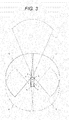
- FIG. 3 is a top view of a vehicle illustrating a radar detection region along with a radar arrangement in the embodiment of the present invention.
- a vehicle-mounted system is mounted on a vehicle 1 (see FIG. 3 ), and includes a plurality of radar units 3 and an electronic control unit (ECU) 4, which are communicably connected to each other via a network 2.
- Each of the radar units 3 includes a radar 5 and an axial deviation detection device 6.
- the electronic control unit 4 and the axial deviation detection device 6 are configured by a computer or the like.
- the plurality of radars 5 are housed in the bumper of the vehicle 1 and arranged on the front right side, the rear right side, the rear left side, the front left side, and the front center of the vehicle 1, respectively.
- the plurality of radars detect surrounding objects (specifically, other vehicles, people, roadside structures, and the like) in a detection region 7 on the front right side of the vehicle 1, a detection region 8 on the rear right side, a detection region 9 on the rear left side, a detection region 10 on the front left side, and a detection region 11 in the front center, respectively.
- the radar 5 is, for example, a millimeter-wave radar that uses millimeter waves (in other words, high-frequency radio waves). The radar transmits radio waves to the surrounding of vehicle 1 and receives reflected waves from surrounding objects, so as to acquire surrounding object data.
- the radar 5 is configured by a radio frequency module (RF) 12, a signal processing board 13, a control board 14, and the like.
- the control board 14 is connected to the network 2 and controls the radio frequency module 12 and the signal processing board 13.
- the radio frequency module 12 includes an antenna for transmitting and receiving radio waves, and a monolithic microwave integrated circuit (MMIC) that converts the radio waves (in other words, reflected waves from the surrounding objects) received by the antenna into electrical signals.
- MMIC monolithic microwave integrated circuit
- the signal processing board 13 performs a process such as fast Fourier transform (FFT) on the electric signal from the radio frequency module 12.
- FFT fast Fourier transform
- the electronic control unit 4 receives an input of the surrounding object data from the radar 5 via the network 2, and controls driving support or autonomous driving of the vehicle 1 based on the input data. Because the control related to the driving support or autonomous driving of the vehicle 1 is known, the description thereof will be omitted.
- the plurality of axial deviation detection devices 6 which are the main components of the present embodiment, receive an input of the surrounding object data from the plurality of radars 5, and detect the axial deviations of the plurality of radars 5 based on the data.
- the axial deviation detection device 6 includes a reference object selection unit 15, a database (DB) 16, a storage unit 17, a same target determination unit 18, an axial deviation detection unit 19, and a correction determination unit 20, as functional components.
- the database 16 and the storage unit 17 are configured by a flash memory and the like.
- the database 16 stores, in advance, reference information for determining whether or not the surrounding object is a movement target.
- the database stores, in advance, the radar cross section (RCS) of a movement target (specifically, another vehicle, a person, and the like) corresponding to the frequency of the radio wave used in the radar 5.
- the radar cross section of a movement target specifically, another vehicle, a person, and the like
- the radar cross section of a person is -10 to 0 dBsm.
- FIG. 4 is a flowchart illustrating the pre-process when the driver has exited the vehicle among processes of the axial deviation detection device in the embodiment of the present invention.
- the axial deviation detection device 6 receives an input of information indicating an ignition OFF (engine stop) and information of a door opening operation, the subsequent door closing operation, and the subsequent door locking operation via the network 2, the axial deviation detection device determines that the driver has exited the vehicle 1.
- the pre-process illustrated in FIG. 4 is started.
- Step S101 the reference object selection unit 15 of the axial deviation detection device 6 determines whether or not surrounding object data has been input from the radar 5 when the driver has exited the vehicle 1.
- Step S101 when vehicle 1 is parked in a vacant lot, there are no surrounding object in the detection region of the radar 5. In this case, the surrounding object data is not input, and thus the determination in Step S101 becomes NO, and the pre-process ends.
- a metal fence 21A and a streetlight pole 22 exist in the detection region 7 on the front right side
- the metal fence 21A and the streetlight pole 22 exist in the detection region 8 on the rear right side
- a sign 23, another vehicle 24, and a metal fence 21B exist in the detection region 9 on the rear left side
- another vehicle 24, the metal fence 21B, a person 25, and a vertical shop 26A exist in the detection region 10 on the front left side
- a vertical shop 26B and the metal fence 21A exist in the detection region 11 in the front center.
- the surrounding object data is input, and thus the determination in Step S101 becomes YES, and the process proceeds to Step S102.
- the surrounding object detected by the radar 5 when the driver has exited the vehicle 1 is referred to as a first surrounding object.
- Step S102 the reference object selection unit 15 of the axial deviation detection device 6 determines whether or not the first surrounding object is stationary based on the relative velocity of the first surrounding object acquired by the radar 5.
- the reference object selection unit 15 determines whether or not the radar cross section of the first surrounding object acquired by the radar 5 is equal to the radar cross section of the movement target stored in advance in the database 16, so as to determine whether or not the first surrounding object is the movement target. Then, the reference object selection unit 15 selects a first reference object that satisfies the condition of being stationary and not being the movement target among the first surrounding objects.
- the metal fence 21A and the streetlight pole 22 are selected as the first reference objects among the metal fences 21A and the streetlight poles 22 existing in the detection region 7 on the front right side.
- the metal fence 21A and the streetlight pole 22 are selected as the first reference objects among the metal fences 21A and the streetlight poles 22 existing in the detection region 8 on the rear right side.
- the sign 23 and the metal fence 21B are selected as the first reference objects among the signs 23, other vehicles 24, and the metal fence 21B existing in the detection region 9 on the rear left side.
- the metal fence 21B and the vertical shop 26A are selected as the first reference objects among the other vehicles 24, the metal fence 21B, the person 25, and the vertical shop 26A existing in the detection region 10 on the front left side.
- the vertical shop 26B and the metal fence 21A are selected as the first reference object among the vertical shop 26B and the metal fence 21A existing in the detection region 11 in the front center.
- Step S103 the reference object selection unit 15 of the axial deviation detection device 6 determines whether or not there is the first reference object. When there is no first reference object, the determination in Step S103 becomes NO, and the pre-process ends. On the other hand, when there is the first reference object, the determination in Step S103 becomes YES, and the process proceeds to Step S104.
- Step S104 the reference object selection unit 15 of the axial deviation detection device 6 selects the relative position of the first reference object among the relative positions of the first surrounding objects, which are acquired by the radar 5, and the reference object selection unit stores the selected relative position in the storage unit 17.
- the reference object selection unit 15 of the axial deviation detection device 6 may select not only the relative position of the first reference object but also the shape and size (or radar cross section) of the first reference object.
- the reference object selection unit may store the selected relative position, shape, and size in the storage unit 17.
- FIG. 6 is a flowchart illustrating the post-process performed when the driver has entered the vehicle among processes of the axial deviation detection device in the embodiment of the present invention.
- the axial deviation detection device 6 receives an input of information of a door unlocking operation via the network 2, the axial deviation detection device determines that the driver has entered the vehicle 1. Thus, the post-process illustrated in FIG. 6 is started.
- Step S201 the reference object selection unit 15 of the axial deviation detection device 6 determines whether or not surrounding object data has been input from the radar 5 when the driver has entered the vehicle 1.
- the surrounding object data is not input from the radar 5, and thus the determination in Step S201 becomes NO, and the post-process ends.
- the determination in Step S201 becomes YES, and the process proceeds to Step S202.
- the surrounding object detected by the radar 5 when the driver has entered the vehicle 1 is referred to as a second surrounding object.
- Step S206 the same target determination unit 18 of the axial deviation detection device 6 determines whether or not there is the same target.
- the determination in Step S206 becomes NO, and the post-process ends.
- the determination in Step S206 becomes YES, and the process proceeds to Step S207.
- Step S210 the correction determination unit 20 of the axial deviation detection device 6 outputs a correction command for the reference axis to the radar 5.
- the control board 14 of the radar 5 corrects the reference axis (in other words, the central axis of the detection region) in response to this correction command.
- Step S211 the correction determination unit 20 of the axial deviation detection device 6 outputs an alarm command to an alarm (specifically, for example, display or buzzer) to generate an alarm.
- the correction determination unit 20 of the axial deviation detection device 6 outputs a travel restriction command to the electronic control unit 4 via the network 2 to restrict travelling of the vehicle 1.
- the axial deviation of the radar 5 it is possible to detect the axial deviation of the radar 5 that occurs while the vehicle 1 is parked, before the vehicle 1 travels. Then, if the axial deviation of the radar 5 is within the range in which the axial deviation can be corrected by software, the axial deviation of the radar 5 is corrected by software, so that it is possible to prevent an occurrence of the error in the surrounding object data. On the other hand, if the axial deviation of the radar 5 is not within the range in which the axial deviation can be corrected by software, it is possible to notify the driver that the hardware needs to be adjusted, by the alarm.
- the reference object selection unit 15 of the axial deviation detection device 6 determines whether or not the radar cross section of the surrounding object acquired by the radar 5 is equal to the radar cross section of the movement target stored in the database 16 in advance, and thereby determines whether or not the surrounding object is the movement target.
- the present invention is not limited to this example, and may be modified in a range without departing from the gist and the technical idea of the present invention.
- the reference object selection unit 15 of the axial deviation detection device 6 may determine whether or not the radar cross section of the surrounding object acquired by the radar 5 is equal to or smaller than a predetermined value set in advance, and thereby may determine whether or not the surrounding object is the movement target.
- the database 16 may store, in advance, the radar cross section of a non-movement target corresponding to the frequency of the radio wave used in the radar 5. Then, the reference object selection unit 15 of the axial deviation detection device 6 may determine whether or not the radar cross section of the surrounding object acquired by the radar 5 is equal to the radar cross section of the non-movement target stored in advance in the database 16, so as to determine whether or not the surrounding object is the movement target.
- the vehicle-mounted system includes the plurality of radar units 3 and the electronic control units 4 that are communicably connected to each other via the network 2 (in other words, when the vehicle-mounted system includes a plurality of axial deviation detection devices 6 that detect the axial deviation of the plurality of radars 5, respectively) is described.
- the present invention is not limited to this example, and may be modified in a range without departing from the gist and the technical idea of the present invention.
- the vehicle-mounted system may include a plurality of radars 5, a deviation detection device 6A, and an electronic control unit 4 that are communicably connected to each other via the network 2.
- the vehicle-mounted system may include one axial deviation detection device 6A that detects the axial deviation of the plurality of radars 5. Also in this modification example, it is possible to obtain the similar effects to those in the above embodiment.
- FIG. 9 is a flowchart illustrating processing of the electronic control unit in this modification example.
- Step S302 the electronic control unit 4 determines whether or not there is a non-detection region, based on the information on the axial deviation of the radar 5. When there is no non-detection region, the determination in Step S302 becomes NO, and the process ends.
- Step S302 when the axial deviation (specifically, deviation angle ⁇ B of the reference axis in the horizontal direction) of the radar 5 mounted on the front right side of the vehicle 1 occurs, and the detection region 7 for the deviation angle is shifted to a detection region 7B, a non-detection region 28 is generated between the detection region 7B and the detection region 11 adjacent to the detection region 7B.
- the determination in Step S302 becomes YES, and the process proceeds to Step S303.
- Step S303 the electronic control unit 4 determines whether or not the non-detection region interferes with the control of the driving support or the autonomous driving of the vehicle 1. Specifically, the electronic control unit determines whether or not the non-detection region is at a position causing interference with the control of the driving support or the autonomous driving of the vehicle 1, and whether or not the non-detection region has a large size enough to interfere with the control of the driving support or the autonomous driving of the vehicle 1. When the non-detection region does not interfere with the control of the driving support or the autonomous driving of the vehicle 1, the determination in Step S303 becomes NO, and the process ends.
- Step S303 when the non-detection region interferes with the control of the driving support or the autonomous driving of the vehicle 1, the determination in Step S303 becomes YES, and the process proceeds to Step S304.
- Step S304 the electronic control unit 4 restricts the traveling of the vehicle 1.
- the radar 5 is a millimeter wave radar.
- the present invention is not limited to this example, and the present invention can be modified in a range without departing from the gist and the technical idea of the present invention.
- the radar 5 may be, for example, a laser radar using a laser (in other words, light).
- the vehicle-mounted system may include a camera that captures the surrounding of the vehicle 1 and an image processing device that processes an image of the camera to detect surrounding objects. Then, the electronic control unit 4 may control the driving support or the autonomous driving of the vehicle 1 based on the surrounding object data acquired by the image processing device. Further, the vehicle-mounted system may include an own-vehicle position acquisition device that acquires the position of the vehicle 1 by using a global positioning system (GPS) and a map information storage device that stores map information. Then, the electronic control unit 4 may control the driving support or autonomous driving of the vehicle 1 based on the position of the vehicle 1 and the map information.
- GPS global positioning system
Landscapes
- Engineering & Computer Science (AREA)
- Radar, Positioning & Navigation (AREA)
- Remote Sensing (AREA)
- Physics & Mathematics (AREA)
- Computer Networks & Wireless Communication (AREA)
- General Physics & Mathematics (AREA)
- Electromagnetism (AREA)
- Radar Systems Or Details Thereof (AREA)
- Traffic Control Systems (AREA)
- Optical Radar Systems And Details Thereof (AREA)
Abstract
Description
- The present invention relates to a device for detecting axial deviation of a radar, a vehicle-mounted system comprising the same, and a method for detecting axial deviation of the radar.
- In recent years, vehicle-mounted systems for performing driving support or autonomous driving of a vehicle have been developed. The vehicle-mounted system includes, for example, a radar that detects a surrounding object (specifically, other vehicles, people, roadside structures, and the like) around the vehicle, and an electronic control unit that controls driving support or autonomous driving of the vehicle based on surrounding object data acquired by the radar.
- The radar is attached to the vehicle so that a reference axis (in other words, central axis of a detection region) is in a predetermined direction. The radar transmits electromagnetic waves (specifically, radio waves or light) to the surrounding of the vehicle and receives reflected waves from the surrounding object to acquire surrounding object data (specifically, relative position, and the like). If axial deviation occurs in the radar for some reasons, an error occurs in surrounding object data acquired by the radar, and the error influences control of driving support or autonomous driving of the vehicle.
-
PTL 1 discloses a method for correcting a reference axis of a radar mounted on a vehicle. In this method, a corner reflector is installed in advance at a predetermined relative position on the assumption that the vehicle stops at a predetermined position. The radar receives reflected waves from the corner reflector, and thereby the radar acquires the direction of the corner reflector, and the reference axis is corrected based on the acquired direction. - PTL 1:
JP 2003-270327 A - Meanwhile, for example, when a vehicle is parked in a public parking area, the vehicle may receive an object collision to deform, and thus the axial deviation may occur in the radar, during a period from when a driver has exited the vehicle until the driver enters the vehicle again. Then, even though the axial deviation occurs in the radar, the driver may not notice the axial deviation. In the method disclosed in
PTL 1, the axial deviation of the radar can be detected and corrected only after the vehicle travels to a specific place where the corner reflector is installed in advance. - The present invention has been made in view of the above circumstances, and an object of the present invention is to provide a device for detecting axial deviation of a radar, a vehicle-mounted system comprising the same, and a method for detecting axial deviation of the radar, in which it is possible to detect axial deviation of a radar, which occurs while a vehicle is parked, before the vehicle travels.
- In order to achieve the above object, the representative of the present invention is an axial deviation detection device for detecting axial deviation of a radar mounted on a vehicle. The device is configured to perform a first process of selecting a first reference object that satisfies a condition of being stationary and not being a movement target from among first surrounding objects, the selection being made based on first surrounding object data acquired by the radar when a driver has exited the vehicle, and selecting and storing a relative position of the first reference object among relative positions of the first surrounding objects, that are acquired by the radar when the driver has exited the vehicle, a second process of, then, selecting a second reference object that satisfies a condition of being stationary and not being a movement target from among second surrounding objects, the selection being made based on second surrounding object data acquired by the radar when the driver has entered the vehicle, and selecting a relative position of the second reference object among relative positions of the second surrounding objects, that are acquired by the radar when the driver has entered the vehicle, and a third process of determining whether or not the first reference object and the second reference object are the same target, and comparing the relative positions of the first reference object and the second reference object that are determined to be the same target, to thereby detect axial deviation of the radar.
- According to the present invention, it is possible to detect axial deviation of a radar, which occurs while a vehicle is parked, before the vehicle travels.
-
- [
FIG. 1] FIG. 1 is a block diagram illustrating a configuration of a vehicle-mounted system according to an embodiment of the present invention. - [
FIG. 2] FIG. 2 is a block diagram illustrating a configuration of a radar unit in the embodiment of the present invention. - [
FIG. 3] FIG. 3 is a top view of a vehicle illustrating a radar detection region along with a radar arrangement in the embodiment of the present invention. - [
FIG. 4] FIG. 4 is a flowchart illustrating a pre-process performed when a driver has exited the vehicle among processes of an axial deviation detection device in the embodiment of the present invention. - [
FIG. 5] FIG. 5 is a top view of a vehicle illustrating a specific example of a surrounding object detected by a radar in the embodiment of the present invention. - [
FIG. 6] FIG. 6 is a flowchart illustrating a post-process performed when the driver has entered the vehicle among processes of the axial deviation detection device in the embodiment of the present invention. - [
FIG. 7] FIG. 7 is a top view of a vehicle illustrating a specific example of the axial deviation of the radar in the embodiment of the present invention. - [
FIG. 8] FIG. 8 is a block diagram illustrating a configuration of a vehicle-mounted system according to a modification example of the present invention. - [
FIG. 9] FIG. 9 is a flowchart illustrating processing of an electronic control unit according to another modification example of the present invention. - [
FIG. 10] FIG. 10 is a top view of a vehicle illustrating a specific example of a non-detection region caused by the axial deviation of the radar in another modification example of the present invention. - An embodiment of the present invention will be described with reference to the drawings.
-
FIG. 1 is a block diagram illustrating a configuration of a vehicle-mounted system according to an embodiment of the present invention.FIG. 2 is a block diagram illustrating a configuration of a radar unit in the embodiment of the present invention.FIG. 3 is a top view of a vehicle illustrating a radar detection region along with a radar arrangement in the embodiment of the present invention. - In the embodiment, a vehicle-mounted system is mounted on a vehicle 1 (see
FIG. 3 ), and includes a plurality ofradar units 3 and an electronic control unit (ECU) 4, which are communicably connected to each other via anetwork 2. Each of theradar units 3 includes aradar 5 and an axialdeviation detection device 6. Theelectronic control unit 4 and the axialdeviation detection device 6 are configured by a computer or the like. - As illustrated in
FIG. 3 , for example, the plurality ofradars 5 are housed in the bumper of thevehicle 1 and arranged on the front right side, the rear right side, the rear left side, the front left side, and the front center of thevehicle 1, respectively. The plurality of radars detect surrounding objects (specifically, other vehicles, people, roadside structures, and the like) in adetection region 7 on the front right side of thevehicle 1, adetection region 8 on the rear right side, adetection region 9 on the rear left side, adetection region 10 on the front left side, and adetection region 11 in the front center, respectively. Theradar 5 is, for example, a millimeter-wave radar that uses millimeter waves (in other words, high-frequency radio waves). The radar transmits radio waves to the surrounding ofvehicle 1 and receives reflected waves from surrounding objects, so as to acquire surrounding object data. - The
radar 5 is configured by a radio frequency module (RF) 12, asignal processing board 13, acontrol board 14, and the like. Thecontrol board 14 is connected to thenetwork 2 and controls theradio frequency module 12 and thesignal processing board 13. Theradio frequency module 12 includes an antenna for transmitting and receiving radio waves, and a monolithic microwave integrated circuit (MMIC) that converts the radio waves (in other words, reflected waves from the surrounding objects) received by the antenna into electrical signals. Thesignal processing board 13 performs a process such as fast Fourier transform (FFT) on the electric signal from theradio frequency module 12. Thus, the surrounding object data (specifically, relative position, relative velocity, radar cross section, and the like) is acquired. - The
electronic control unit 4 receives an input of the surrounding object data from theradar 5 via thenetwork 2, and controls driving support or autonomous driving of thevehicle 1 based on the input data. Because the control related to the driving support or autonomous driving of thevehicle 1 is known, the description thereof will be omitted. - The plurality of axial
deviation detection devices 6, which are the main components of the present embodiment, receive an input of the surrounding object data from the plurality ofradars 5, and detect the axial deviations of the plurality ofradars 5 based on the data. The axialdeviation detection device 6 includes a referenceobject selection unit 15, a database (DB) 16, astorage unit 17, a sametarget determination unit 18, an axialdeviation detection unit 19, and acorrection determination unit 20, as functional components. Thedatabase 16 and thestorage unit 17 are configured by a flash memory and the like. - The
database 16 stores, in advance, reference information for determining whether or not the surrounding object is a movement target. Specifically, for example, the database stores, in advance, the radar cross section (RCS) of a movement target (specifically, another vehicle, a person, and the like) corresponding to the frequency of the radio wave used in theradar 5. For example, if the frequency of the radio wave used in theradar 5 is 76 GHz, the radar cross section of another vehicle is 5 to 15 dBsm, and the radar cross section of a person is -10 to 0 dBsm. - The processing of the axial
deviation detection device 6 is roughly divided into a pre-process performed when a driver has exited thevehicle 1 and a post-process performed when the driver has entered thevehicle 1 after the exit. Firstly, the pre-process performed when the driver has exited thevehicle 1 will be described.FIG. 4 is a flowchart illustrating the pre-process when the driver has exited the vehicle among processes of the axial deviation detection device in the embodiment of the present invention. - For example, when the axial
deviation detection device 6 receives an input of information indicating an ignition OFF (engine stop) and information of a door opening operation, the subsequent door closing operation, and the subsequent door locking operation via thenetwork 2, the axial deviation detection device determines that the driver has exited thevehicle 1. Thus, the pre-process illustrated inFIG. 4 is started. - Firstly, in Step S101, the reference
object selection unit 15 of the axialdeviation detection device 6 determines whether or not surrounding object data has been input from theradar 5 when the driver has exited thevehicle 1. - For example, when
vehicle 1 is parked in a vacant lot, there are no surrounding object in the detection region of theradar 5. In this case, the surrounding object data is not input, and thus the determination in Step S101 becomes NO, and the pre-process ends. - For example, as illustrated in
FIG. 5 , when thevehicle 1 is parked in a public parking area, ametal fence 21A and astreetlight pole 22 exist in thedetection region 7 on the front right side, themetal fence 21A and thestreetlight pole 22 exist in thedetection region 8 on the rear right side, asign 23, anothervehicle 24, and ametal fence 21B exist in thedetection region 9 on the rear left side, anothervehicle 24, themetal fence 21B, aperson 25, and avertical shop 26A exist in thedetection region 10 on the front left side, avertical shop 26B and themetal fence 21A exist in thedetection region 11 in the front center. In this case, the surrounding object data is input, and thus the determination in Step S101 becomes YES, and the process proceeds to Step S102. Note that, the surrounding object detected by theradar 5 when the driver has exited thevehicle 1 is referred to as a first surrounding object. - In Step S102, the reference
object selection unit 15 of the axialdeviation detection device 6 determines whether or not the first surrounding object is stationary based on the relative velocity of the first surrounding object acquired by theradar 5. - In addition, the reference
object selection unit 15 determines whether or not the radar cross section of the first surrounding object acquired by theradar 5 is equal to the radar cross section of the movement target stored in advance in thedatabase 16, so as to determine whether or not the first surrounding object is the movement target. Then, the referenceobject selection unit 15 selects a first reference object that satisfies the condition of being stationary and not being the movement target among the first surrounding objects. - Describing with a specific example of the surrounding object illustrated in
FIG. 5 , themetal fence 21A and thestreetlight pole 22 are selected as the first reference objects among themetal fences 21A and thestreetlight poles 22 existing in thedetection region 7 on the front right side. Themetal fence 21A and thestreetlight pole 22 are selected as the first reference objects among themetal fences 21A and thestreetlight poles 22 existing in thedetection region 8 on the rear right side. Thesign 23 and themetal fence 21B are selected as the first reference objects among thesigns 23,other vehicles 24, and themetal fence 21B existing in thedetection region 9 on the rear left side. Themetal fence 21B and thevertical shop 26A are selected as the first reference objects among theother vehicles 24, themetal fence 21B, theperson 25, and thevertical shop 26A existing in thedetection region 10 on the front left side. Thevertical shop 26B and themetal fence 21A are selected as the first reference object among thevertical shop 26B and themetal fence 21A existing in thedetection region 11 in the front center. - Proceeding to Step S103, the reference
object selection unit 15 of the axialdeviation detection device 6 determines whether or not there is the first reference object. When there is no first reference object, the determination in Step S103 becomes NO, and the pre-process ends. On the other hand, when there is the first reference object, the determination in Step S103 becomes YES, and the process proceeds to Step S104. - In Step S104, the reference
object selection unit 15 of the axialdeviation detection device 6 selects the relative position of the first reference object among the relative positions of the first surrounding objects, which are acquired by theradar 5, and the reference object selection unit stores the selected relative position in thestorage unit 17. The referenceobject selection unit 15 of the axialdeviation detection device 6 may select not only the relative position of the first reference object but also the shape and size (or radar cross section) of the first reference object. The reference object selection unit may store the selected relative position, shape, and size in thestorage unit 17. - Next, the post-process performed when the driver has entered the
vehicle 1 will be described.FIG. 6 is a flowchart illustrating the post-process performed when the driver has entered the vehicle among processes of the axial deviation detection device in the embodiment of the present invention. - For example, when the axial
deviation detection device 6 receives an input of information of a door unlocking operation via thenetwork 2, the axial deviation detection device determines that the driver has entered thevehicle 1. Thus, the post-process illustrated inFIG. 6 is started. - Firstly, in Step S201, the reference
object selection unit 15 of the axialdeviation detection device 6 determines whether or not surrounding object data has been input from theradar 5 when the driver has entered thevehicle 1. When the surrounding object data is not input from theradar 5, and thus the determination in Step S201 becomes NO, and the post-process ends. On the other hand, when the surrounding object data is input from theradar 5, the determination in Step S201 becomes YES, and the process proceeds to Step S202. Note that, the surrounding object detected by theradar 5 when the driver has entered thevehicle 1 is referred to as a second surrounding object. - In Step S202, the reference
object selection unit 15 of the axialdeviation detection device 6 determines whether or not the second surrounding object is stationary based on the relative velocity of the second surrounding object acquired by theradar 5. - In addition, the reference
object selection unit 15 determines whether or not the radar cross section of the second surrounding object acquired by theradar 5 is equal to the radar cross section of the movement target stored in advance in thedatabase 16, so as to determine whether or not the second surrounding object is the movement target. Then, the referenceobject selection unit 15 selects a second reference object that satisfies the condition of being stationary and not being the movement target among the second surrounding objects. - Then, the process proceeds to Step S203, and the reference
object selection unit 15 of the axialdeviation detection device 6 determines whether or not there is a second reference object. When there is no second reference object, the determination in Step S203 becomes NO, and the post-process ends. On the other hand, when there is the second reference object, the determination in Step S203 becomes YES, and the process proceeds to Step S204. In Step S204, the referenceobject selection unit 15 of the axialdeviation detection device 6 selects the relative position of the second reference object among pieces of second surrounding object data acquired by theradar 5. The referenceobject selection unit 15 of the axialdeviation detection device 6 may select not only the relative position of the second reference object but also the shape and size (or radar cross section) of the second reference object. - Then, the process proceeds to Step S205. The same
target determination unit 18 of the axialdeviation detection device 6 determines, for example, whether or not a difference between the relative position of the first reference object (stored in thestorage unit 17 in Step S104 described above) and the relative position of the second reference object (selected in Step S204 described above) is within a predetermined range set in advance, and thereby determines whether or not the first reference object and the second reference object are the same target. Note that, the sametarget determination unit 18 of the axialdeviation detection device 6 may determine whether or not the shape or size (or radar cross section) of the first reference object stored in thestorage unit 17 in Step S104 described above is similar to the shape or size (or radar cross section) of the second reference object selected in Step S204 described above, and thereby determine whether or not the first reference object and the second reference object are the same target. - Then, the process proceeds to Step S206, and the same
target determination unit 18 of the axialdeviation detection device 6 determines whether or not there is the same target. When there is no same target, the determination in Step S206 becomes NO, and the post-process ends. On the other hand, when there is the same target, the determination in Step S206 becomes YES, and the process proceeds to Step S207. - In Step S207, the axial
deviation detection unit 19 of the axialdeviation detection device 6 compares the relative positions (in particular, relative directions) of the first reference object and the second reference object determined to be the same target to each other, and thereby detects the axial deviation (specifically, deviation angle of the reference axis in at least one of a horizontal direction and a vertical direction) of theradar 5. Then, the process proceeds to Step S208. The axialdeviation detection unit 19 of the axialdeviation detection device 6 determines whether or not the deviation angle of the reference axis of theradar 5 is equal to or larger than a threshold value set in advance, and thereby determines whether or not the axial deviation of theradar 5 occurs. When there is no axial deviation of the radar 5 (in other words, when the deviation angle of the reference axis is smaller than the threshold value), the determination in Step S208 becomes NO, and the post-process ends. On the other hand, for example, as illustrated inFIG. 7 , the axial deviation (specifically, deviation angle θA of the reference axis in the horizontal direction) of theradar 5 mounted on the front right side of thevehicle 1 occurs. Thus, when thedetection region 7 for the axial deviation is deviated to adetection region 7A, therelative position 27 of thestreetlight pole 22 is shifted to arelative position 27A. Then, when there is the axial deviation of the radar 5 (in other words, when the deviation angle of the reference axis is equal to or larger than the threshold value), the determination in Step S208 becomes YES, and the process proceeds to Step S209. - In Step S209, the
correction determination unit 20 of the axialdeviation detection device 6 determines whether or not the axial deviation of theradar 5 is within a range in which the axial deviation of theradar 5 can be corrected by software. When the axial deviation of theradar 5 is within the correctable range, the determination in Step S209 becomes YES, and the process proceeds to Step S210. - In Step S210, the
correction determination unit 20 of the axialdeviation detection device 6 outputs a correction command for the reference axis to theradar 5. Thecontrol board 14 of theradar 5 corrects the reference axis (in other words, the central axis of the detection region) in response to this correction command. - On the other hand, when the axial deviation of the
radar 5 is not within the correctable range, the determination in Step S209 becomes NO, and the process proceeds to Step S211. In Step S211 thecorrection determination unit 20 of the axialdeviation detection device 6 outputs an alarm command to an alarm (specifically, for example, display or buzzer) to generate an alarm. In addition, thecorrection determination unit 20 of the axialdeviation detection device 6 outputs a travel restriction command to theelectronic control unit 4 via thenetwork 2 to restrict travelling of thevehicle 1. - As described above, in the embodiment, it is possible to detect the axial deviation of the
radar 5 that occurs while thevehicle 1 is parked, before thevehicle 1 travels. Then, if the axial deviation of theradar 5 is within the range in which the axial deviation can be corrected by software, the axial deviation of theradar 5 is corrected by software, so that it is possible to prevent an occurrence of the error in the surrounding object data. On the other hand, if the axial deviation of theradar 5 is not within the range in which the axial deviation can be corrected by software, it is possible to notify the driver that the hardware needs to be adjusted, by the alarm. - Note that, in the above embodiment, an example in which the reference
object selection unit 15 of the axialdeviation detection device 6 determines whether or not the radar cross section of the surrounding object acquired by theradar 5 is equal to the radar cross section of the movement target stored in thedatabase 16 in advance, and thereby determines whether or not the surrounding object is the movement target is described. The present invention is not limited to this example, and may be modified in a range without departing from the gist and the technical idea of the present invention. For example, the referenceobject selection unit 15 of the axialdeviation detection device 6 may determine whether or not the radar cross section of the surrounding object acquired by theradar 5 is equal to or smaller than a predetermined value set in advance, and thereby may determine whether or not the surrounding object is the movement target. Alternatively, thedatabase 16 may store, in advance, the radar cross section of a non-movement target corresponding to the frequency of the radio wave used in theradar 5. Then, the referenceobject selection unit 15 of the axialdeviation detection device 6 may determine whether or not the radar cross section of the surrounding object acquired by theradar 5 is equal to the radar cross section of the non-movement target stored in advance in thedatabase 16, so as to determine whether or not the surrounding object is the movement target. - Alternatively, the
database 16 may store the shape and size of the movement target in advance. Then, the referenceobject selection unit 15 of the axialdeviation detection device 6 may determine whether the shape or size of the surrounding object acquired by theradar 5 are similar to the shape or size of the movement target stored in advance in thedatabase 16, and thereby determine whether or not the surrounding object is the movement target. Alternatively, thedatabase 16 may store the shape or size of the non-movement target in advance. Then, the referenceobject selection unit 15 of the axialdeviation detection device 6 may determine whether the shape or size of the surrounding object acquired by theradar 5 are similar to the shape of the non-movement target stored in advance in thedatabase 16, and thereby determine whether or not the surrounding object is the non-movement target. - Further, in the embodiment, an example in which the vehicle-mounted system includes the plurality of
radar units 3 and theelectronic control units 4 that are communicably connected to each other via the network 2 (in other words, when the vehicle-mounted system includes a plurality of axialdeviation detection devices 6 that detect the axial deviation of the plurality ofradars 5, respectively) is described. The present invention is not limited to this example, and may be modified in a range without departing from the gist and the technical idea of the present invention. For example, as in the modification example illustrated inFIG. 9 , the vehicle-mounted system may include a plurality ofradars 5, adeviation detection device 6A, and anelectronic control unit 4 that are communicably connected to each other via thenetwork 2. In other words, the vehicle-mounted system may include one axialdeviation detection device 6A that detects the axial deviation of the plurality ofradars 5. Also in this modification example, it is possible to obtain the similar effects to those in the above embodiment. - The above-described axial
deviation detection device 6A may compare the relative positions of the reference object, which are acquired by tworadars 5, the reference object existing in the overlapping portion of the detection regions of the tworadars 5, and thereby detect the axial deviation of theradar 5. - Further, in the above embodiment and the above modification examples, an example in which, when the axial deviation of the
radar 5 is not within the correctable range, thecorrection determination unit 20 of the axialdeviation detection device electronic control unit 4 via thenetwork 2 to restrict the traveling of thevehicle 1 is described. The present invention is not limited to this example, and may be modified in a range without departing from the gist and the technical idea of the present invention. For example, thecorrection determination unit 20 of the axialdeviation detection device radar 5 to theelectronic control unit 4 via thenetwork 2 when the axial deviation of theradar 5 is not within the correctable range. In such a modification example, the processing of theelectronic control unit 4 will be described with reference toFIGS. 9 and10 .FIG. 9 is a flowchart illustrating processing of the electronic control unit in this modification example. - In Step S301, the
electronic control unit 4 determines whether or not the information on the axial deviation of theradar 5 has been input. When the information on the axial deviation of theradar 5 is not input, the determination in Step S301 becomes NO, and the process ends. On the other hand, when the information on the axial deviation of theradar 5 is input, the determination in Step S301 becomes YES, and the process proceeds to Step S302. - In Step S302, the
electronic control unit 4 determines whether or not there is a non-detection region, based on the information on the axial deviation of theradar 5. When there is no non-detection region, the determination in Step S302 becomes NO, and the process ends. - On the other hand, for example, as illustrated in
FIG. 10 , when the axial deviation (specifically, deviation angle θB of the reference axis in the horizontal direction) of theradar 5 mounted on the front right side of thevehicle 1 occurs, and thedetection region 7 for the deviation angle is shifted to adetection region 7B, anon-detection region 28 is generated between thedetection region 7B and thedetection region 11 adjacent to thedetection region 7B. When such a non-detection region is generated, the determination in Step S302 becomes YES, and the process proceeds to Step S303. - In Step S303, the
electronic control unit 4 determines whether or not the non-detection region interferes with the control of the driving support or the autonomous driving of thevehicle 1. Specifically, the electronic control unit determines whether or not the non-detection region is at a position causing interference with the control of the driving support or the autonomous driving of thevehicle 1, and whether or not the non-detection region has a large size enough to interfere with the control of the driving support or the autonomous driving of thevehicle 1. When the non-detection region does not interfere with the control of the driving support or the autonomous driving of thevehicle 1, the determination in Step S303 becomes NO, and the process ends. On the other hand, when the non-detection region interferes with the control of the driving support or the autonomous driving of thevehicle 1, the determination in Step S303 becomes YES, and the process proceeds to Step S304. In Step S304, theelectronic control unit 4 restricts the traveling of thevehicle 1. - In the above embodiment and the above modification examples, an example in which the
radar 5 is a millimeter wave radar is described. The present invention is not limited to this example, and the present invention can be modified in a range without departing from the gist and the technical idea of the present invention. Theradar 5 may be, for example, a laser radar using a laser (in other words, light). - Further, although not particularly described in the above embodiment and the above modification examples, the vehicle-mounted system may include a camera that captures the surrounding of the
vehicle 1 and an image processing device that processes an image of the camera to detect surrounding objects. Then, theelectronic control unit 4 may control the driving support or the autonomous driving of thevehicle 1 based on the surrounding object data acquired by the image processing device. Further, the vehicle-mounted system may include an own-vehicle position acquisition device that acquires the position of thevehicle 1 by using a global positioning system (GPS) and a map information storage device that stores map information. Then, theelectronic control unit 4 may control the driving support or autonomous driving of thevehicle 1 based on the position of thevehicle 1 and the map information. -
- 1
- vehicle
- 5
- radar
- 6, 6A
- axial deviation detection device
- 21A, 21B
- metal fence (surrounding object, reference object)
- 22
- streetlight pole (surrounding object, reference object)
- 23
- sign (surrounding object, reference object)
- 24
- other vehicles (surrounding object)
- 25
- person (surrounding object)
- 26A, 26B
- vertical shop (reference object)
Claims (8)
- A device for detecting axial deviation of a radar mounted on a vehicle, the device configured to perform
a first process of selecting a first reference object that satisfies a condition of being stationary and not being a movement target from among first surrounding objects, the selection being made based on first surrounding object data acquired by the radar when a driver has exited the vehicle, and selecting and storing a relative position of the first reference object among relative positions of the first surrounding objects, that are acquired by the radar when the driver has exited the vehicle,
a second process of, then, selecting a second reference object that satisfies a condition of being stationary and not being a movement target from among second surrounding objects, the selection being made based on second surrounding object data acquired by the radar when the driver has entered the vehicle, and selecting a relative position of the second reference object among relative positions of the second surrounding objects, that are acquired by the radar when the driver has entered the vehicle, and
a third process of determining whether or not the first reference object and the second reference object are the same target, and comparing the relative positions of the first reference object and the second reference object that are determined to be the same target, to thereby detect axial deviation of the radar. - The device for detecting axial deviation of a radar according to claim 1, wherein the device is configured to perform a fourth process of determining whether or not the axial deviation of the radar is within a correctable range, and a fifth process of outputting a correction command of a reference axis of the radar when the axial deviation of the radar is within the correctable range.
- The device for detecting axial deviation of a radar according to claim 2, wherein the device is configured to perform a sixth process of outputting an alarm command when the axial deviation of the radar is not within the correctable range.
- A vehicle-mounted system comprising:a radar that detects a surrounding object around a vehicle;an electronic control unit that controls driving support or autonomous driving of the vehicle based on surrounding object data acquired by the radar; andan axial deviation detection device that detects axial deviation of the radar,wherein the axial deviation detection device is configured to performa first process of selecting a first reference object that satisfies a condition of being stationary and not being a movement target from among first surrounding objects, the selection being made based on first surrounding object data acquired by the radar when a driver has exited the vehicle, and selecting and storing a relative position of the first reference object among relative positions of the first surrounding objects, that are acquired by the radar when the driver has exited the vehicle,a second process of, then, selecting a second reference object that satisfies a condition of being stationary and not being a movement target from among second surrounding objects, the selection being made based on second surrounding object data acquired by the radar when the driver has entered the vehicle, and selecting a relative position of the second reference object among relative positions of the second surrounding objects, that are acquired by the radar when the driver has entered the vehicle,a third process of determining whether or not the first reference object and the second reference object are the same target, comparing the relative positions of the first reference object and the second reference object, that are determined to be the same target, to thereby detect axial deviation of the radar,a fourth process of determining whether or not the axial deviation of the radar is within a correctable range,a fifth process of outputting a correction command of a reference axis of the radar when the axial deviation of the radar is within the correctable range, anda sixth process of outputting an alarm command and outputting information on the axial deviation of the radar to the electronic control unit, when the axial deviation of the radar is not within the correctable range, andthe electronic control unit is configured to performa seventh process of determining whether or not a non-detection region is generated, based on the information on the axial deviation of the radar,an eighth process of determining whether or not the non-detection region interferes with control of driving support or autonomous driving of the vehicle, when the non-detection region is generated, anda ninth process of restricting traveling of the vehicle when the non-detection region interferes with the control of the driving support or the autonomous driving of the vehicle.
- A method for detecting axial deviation of a radar mounted on a vehicle, the method comprising:a first process of selecting a first reference object that satisfies a condition of being stationary and not being a movement target from among first surrounding objects, the selection being made based on first surrounding object data acquired by the radar when a driver has exited the vehicle, and selecting and storing a relative position of the first reference object among relative positions of the first surrounding objects, that are acquired by the radar when the driver has exited the vehicle;a second process of, then, selecting a second reference object that satisfies a condition of being stationary and not being a movement target from among second surrounding objects, the selection being made based on second surrounding object data acquired by the radar when the driver has entered the vehicle, and selecting a relative position of the second reference object among relative positions of the second surrounding objects, that are acquired by the radar when the driver has entered the vehicle; anda third process of determining whether or not the first reference object and the second reference object are the same target, and comparing the relative positions of the first reference object and the second reference object that are determined to be the same target, to thereby detect axial deviation of the radar.
- The method for detecting axial deviation of a radar according to claim 5, further comprising:a fourth process of determining whether or not the axial deviation of the radar is within a correctable range; anda fifth process of outputting a correction command of a reference axis of the radar when the axial deviation of the radar is within the correctable range.
- The method for detecting axial deviation of a radar according to claim 6, further comprising
a sixth process of outputting an alarm command when the axial deviation of the radar is not within the correctable range. - The method for detecting axial deviation of a radar according to claim 7, further comprising:a seventh process of determining whether or not a non-detection region is generated, based on information on the axial deviation of the radar, when the axial deviation of the radar is not within the correctable range;an eighth process of determining whether or not the non-detection region interferes with control of driving support or autonomous driving of the vehicle, when the non-detection region is generated; anda ninth process of restricting traveling of the vehicle when the non-detection region interferes with the control of the driving support or the autonomous driving of the vehicle.
Applications Claiming Priority (2)
| Application Number | Priority Date | Filing Date | Title |
|---|---|---|---|
| JP2018168865 | 2018-09-10 | ||
| PCT/JP2019/033415 WO2020054392A1 (en) | 2018-09-10 | 2019-08-27 | Device for detecting axial deviation of radar, vehicle-mounted system comprising same, and method for detecting axial deviation of radar |
Publications (2)
| Publication Number | Publication Date |
|---|---|
| EP3851868A1 true EP3851868A1 (en) | 2021-07-21 |
| EP3851868A4 EP3851868A4 (en) | 2022-05-18 |
Family
ID=69777505
Family Applications (1)
| Application Number | Title | Priority Date | Filing Date |
|---|---|---|---|
| EP19859556.3A Pending EP3851868A4 (en) | 2018-09-10 | 2019-08-27 | Device for detecting axial deviation of radar, vehicle-mounted system comprising same, and method for detecting axial deviation of radar |
Country Status (4)
| Country | Link |
|---|---|
| EP (1) | EP3851868A4 (en) |
| JP (1) | JPWO2020054392A1 (en) |
| CN (1) | CN112639508B (en) |
| WO (1) | WO2020054392A1 (en) |
Families Citing this family (4)
| Publication number | Priority date | Publication date | Assignee | Title |
|---|---|---|---|---|
| DE102020007645A1 (en) * | 2020-04-03 | 2021-10-07 | Daimler Ag | Method for calibrating a lidar sensor |
| CN113534136B (en) * | 2020-04-22 | 2023-07-28 | 宇通客车股份有限公司 | Method and system for detecting left-over children in vehicle |
| CN115989315A (en) | 2020-07-15 | 2023-04-18 | 本纳曼恩服务有限公司 | System and method for anaerobic digestion |
| CN113702929B (en) * | 2021-08-16 | 2024-07-05 | 中汽创智科技有限公司 | Method, device, equipment and storage medium for calibrating installation angle of vehicle-mounted radar |
Family Cites Families (12)
| Publication number | Priority date | Publication date | Assignee | Title |
|---|---|---|---|---|
| JP2003270327A (en) | 2002-03-20 | 2003-09-25 | Murata Mfg Co Ltd | Radar, radar system, and method for setting reference direction for radar |
| JP4895484B2 (en) * | 2004-06-28 | 2012-03-14 | 富士通テン株式会社 | Axis deviation calculation method for on-vehicle radar device and on-vehicle radar axis deviation determination method |
| JP2009281862A (en) * | 2008-05-22 | 2009-12-03 | Toyota Motor Corp | Axis adjusting method of radar device and axis adjusting device |
| JP5166975B2 (en) * | 2008-05-26 | 2013-03-21 | 富士通テン株式会社 | Vehicle periphery monitoring device and vehicle periphery monitoring method |
| JP2010127743A (en) * | 2008-11-27 | 2010-06-10 | Fujitsu Ten Ltd | Radar system and moving body |
| JP5551892B2 (en) * | 2009-06-19 | 2014-07-16 | 富士通テン株式会社 | Signal processing apparatus and radar apparatus |
| DE102013208735A1 (en) * | 2013-05-13 | 2014-11-13 | Robert Bosch Gmbh | Method and device for determining and compensating for a misalignment angle of a radar sensor of a vehicle |
| JP6475543B2 (en) * | 2015-03-31 | 2019-02-27 | 株式会社デンソー | Vehicle control apparatus and vehicle control method |
| JP6321576B2 (en) * | 2015-05-12 | 2018-05-09 | トヨタ自動車株式会社 | Limiting device and vehicle |
| JP6564290B2 (en) * | 2015-09-29 | 2019-08-21 | 株式会社Subaru | Automatic driving device |
| US10591584B2 (en) * | 2016-10-25 | 2020-03-17 | GM Global Technology Operations LLC | Radar calibration with known global positioning of static objects |
| DE102017210112A1 (en) * | 2017-06-16 | 2018-12-20 | Robert Bosch Gmbh | Method and system for performing a calibration of a sensor |
-
2019
- 2019-08-27 WO PCT/JP2019/033415 patent/WO2020054392A1/en unknown
- 2019-08-27 JP JP2020546827A patent/JPWO2020054392A1/en active Pending
- 2019-08-27 EP EP19859556.3A patent/EP3851868A4/en active Pending
- 2019-08-27 CN CN201980051711.2A patent/CN112639508B/en active Active
Also Published As
| Publication number | Publication date |
|---|---|
| WO2020054392A1 (en) | 2020-03-19 |
| CN112639508B (en) | 2024-03-29 |
| CN112639508A (en) | 2021-04-09 |
| EP3851868A4 (en) | 2022-05-18 |
| JPWO2020054392A1 (en) | 2021-08-30 |
Similar Documents
| Publication | Publication Date | Title |
|---|---|---|
| EP3851868A1 (en) | Device for detecting axial deviation of radar, vehicle-mounted system comprising same, and method for detecting axial deviation of radar | |
| US11027653B2 (en) | Apparatus, system and method for preventing collision | |
| EP2023158A2 (en) | Automotive forward looking sensor with identification of traversable stationary obstacles in the driving path | |
| KR100803414B1 (en) | Near object detection system | |
| US9500748B2 (en) | Target recognition apparatus | |
| US20110285571A1 (en) | Sensor and alignment adjusting method | |
| EP3865904A1 (en) | Electronic device, electronic device control method, and electronic device control program | |
| CN111699404B (en) | Driving auxiliary target acquisition method and device, radar, driving system and vehicle | |
| US10191148B2 (en) | Radar system for vehicle and method for measuring azimuth therein | |
| EP3865909A1 (en) | Electronic device, method for controlling electronic device, and program for controlling electronic device | |
| JP2001216596A (en) | Road detector and automatic vehicle | |
| JP2004085258A (en) | Radar equipment | |
| US10343696B2 (en) | Travel control device of vehicle | |
| JP6690593B2 (en) | Perimeter monitoring radar device | |
| JP2006047140A (en) | Method and detector for detecting axial shift in radar system | |
| KR100875564B1 (en) | Near Object Detection System | |
| US11933887B2 (en) | Apparatus and method for controlling radar | |
| EP4254006A1 (en) | Electronic device, method for controlling electronic device, and program | |
| EP3859383A1 (en) | Electronic device, control method for electronic device, and control program for electronic device | |
| JP2000099875A (en) | Vehicle detector | |
| JP2001084485A (en) | Vehicle detector | |
| US20210141078A1 (en) | Detection system and method for characterizing targets | |
| JP2000111644A (en) | Vehicle detecting device | |
| JP2019079315A (en) | In-vehicle system, target recognition method, and computer program | |
| US11977142B2 (en) | Electronic device, control method of electronic device, and control program of electronic device |
Legal Events
| Date | Code | Title | Description |
|---|---|---|---|
| STAA | Information on the status of an ep patent application or granted ep patent |
Free format text: STATUS: THE INTERNATIONAL PUBLICATION HAS BEEN MADE |
|
| PUAI | Public reference made under article 153(3) epc to a published international application that has entered the european phase |
Free format text: ORIGINAL CODE: 0009012 |
|
| STAA | Information on the status of an ep patent application or granted ep patent |
Free format text: STATUS: REQUEST FOR EXAMINATION WAS MADE |
|
| 17P | Request for examination filed |
Effective date: 20210412 |
|
| AK | Designated contracting states |
Kind code of ref document: A1 Designated state(s): AL AT BE BG CH CY CZ DE DK EE ES FI FR GB GR HR HU IE IS IT LI LT LU LV MC MK MT NL NO PL PT RO RS SE SI SK SM TR |
|
| RAP3 | Party data changed (applicant data changed or rights of an application transferred) |
Owner name: HITACHI ASTEMO, LTD. |
|
| DAV | Request for validation of the european patent (deleted) | ||
| DAX | Request for extension of the european patent (deleted) | ||
| A4 | Supplementary search report drawn up and despatched |
Effective date: 20220419 |
|
| RIC1 | Information provided on ipc code assigned before grant |
Ipc: G01S 17/931 20200101ALI20220411BHEP Ipc: G01S 13/931 20200101ALI20220411BHEP Ipc: G01S 7/497 20060101ALI20220411BHEP Ipc: G01S 7/40 20060101AFI20220411BHEP |