EP3851846A1 - Defect inspection device for steel plate - Google Patents
Defect inspection device for steel plate Download PDFInfo
- Publication number
- EP3851846A1 EP3851846A1 EP21161512.5A EP21161512A EP3851846A1 EP 3851846 A1 EP3851846 A1 EP 3851846A1 EP 21161512 A EP21161512 A EP 21161512A EP 3851846 A1 EP3851846 A1 EP 3851846A1
- Authority
- EP
- European Patent Office
- Prior art keywords
- steel plate
- defect
- inspection
- magnetic flux
- present disclosure
- Prior art date
- Legal status (The legal status is an assumption and is not a legal conclusion. Google has not performed a legal analysis and makes no representation as to the accuracy of the status listed.)
- Pending
Links
Images





Classifications
-
- G—PHYSICS
- G01—MEASURING; TESTING
- G01N—INVESTIGATING OR ANALYSING MATERIALS BY DETERMINING THEIR CHEMICAL OR PHYSICAL PROPERTIES
- G01N27/00—Investigating or analysing materials by the use of electric, electrochemical, or magnetic means
- G01N27/72—Investigating or analysing materials by the use of electric, electrochemical, or magnetic means by investigating magnetic variables
- G01N27/82—Investigating or analysing materials by the use of electric, electrochemical, or magnetic means by investigating magnetic variables for investigating the presence of flaws
- G01N27/90—Investigating or analysing materials by the use of electric, electrochemical, or magnetic means by investigating magnetic variables for investigating the presence of flaws using eddy currents
- G01N27/9006—Details, e.g. in the structure or functioning of sensors
-
- G—PHYSICS
- G01—MEASURING; TESTING
- G01N—INVESTIGATING OR ANALYSING MATERIALS BY DETERMINING THEIR CHEMICAL OR PHYSICAL PROPERTIES
- G01N27/00—Investigating or analysing materials by the use of electric, electrochemical, or magnetic means
- G01N27/72—Investigating or analysing materials by the use of electric, electrochemical, or magnetic means by investigating magnetic variables
- G01N27/82—Investigating or analysing materials by the use of electric, electrochemical, or magnetic means by investigating magnetic variables for investigating the presence of flaws
-
- G—PHYSICS
- G01—MEASURING; TESTING
- G01N—INVESTIGATING OR ANALYSING MATERIALS BY DETERMINING THEIR CHEMICAL OR PHYSICAL PROPERTIES
- G01N27/00—Investigating or analysing materials by the use of electric, electrochemical, or magnetic means
- G01N27/72—Investigating or analysing materials by the use of electric, electrochemical, or magnetic means by investigating magnetic variables
- G01N27/82—Investigating or analysing materials by the use of electric, electrochemical, or magnetic means by investigating magnetic variables for investigating the presence of flaws
- G01N27/83—Investigating or analysing materials by the use of electric, electrochemical, or magnetic means by investigating magnetic variables for investigating the presence of flaws by investigating stray magnetic fields
- G01N27/87—Investigating or analysing materials by the use of electric, electrochemical, or magnetic means by investigating magnetic variables for investigating the presence of flaws by investigating stray magnetic fields using probes
Definitions
- the present disclosure relates to a device for inspecting defects present in an interior portion or a surface of a steel plate using a leakage magnetic flux.
- Technologies for detecting defects in a steel plate may include an ultrasonic test, a magnetic flux leakage inspection, a magnetic particle inspection, an eddy-current inspection, an optical inspection method and the like.
- a magnetic flux leakage inspection is a scheme of detecting a portion of magnetic flux leaked to the outside of a steel plate due to defects present in a steel plate when the steel plate is magnetized in a certain direction, using a magnetic sensor or a hall sensor.
- Such a magnetic flux leakage inspection may have superior performance in terms of the detection of crack defects occurring in a surface or below a surface layer of a ferromagnetic metal, and an example of an inspection device using the magnetic flux leakage described above is disclosed in Cited Document (Korean Patent Laid-Open Publication No. 2010-0076838 ).
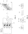
- a magnetizer 120 may be disposed an on upper portion of a steel plate 10 wound around a roll 110. Electromagnetic poles 121a and 121b are alternately arranged in a lower region of the magnetizer 120 and a coil 122 is wound an an upper region of the magnetizer 120.
- the steel plate 10 may be magnetized in a direction from the electromagnetic pole 121a having N-polarity to the electromagnetic pole 121b having S-polarity.
- a leakage magnetic flux may be sensed by a sensor 131 disposed between the electromagnetic poles 121a and 121b, such that defects present in the steel plate 10 may be detected.
- the electromagnetic poles 121a and 121b may be spaced apart from each other by a predetermined interval and be configured such that they are inclined at a certain angle (0) with respect to a rolling direction and thus, are formed to a boundary line A at which the steel plate 10 comes into contact with the roll 110, in a spiral manner.
- the magnetizer 120 may have an integrated structure in which a plurality of the electromagnetic poles 121a and 121b may be integrally provided. Therefore, it may be unfeasible to replace only some units such as the electromagnetic poles 121a and 121b or the sensor 131, leading to difficulties in terms of maintenance and management.
- An aspect of the present disclosure provides a device for inspecting defects in a steel plate, the device being capable of accurately detecting defects in surfaces or in interior portions of the steel plate.
- An aspect of the present disclosure also provides a device for inspecting defects in a steel plate, the device allowing for efficient maintenance and management thereof.
- An aspect of the present disclosure also provides a device for inspecting defects in a steel plate, the device being capable of separately detecting a surface defect and an interior defect or accurately determining a position of the interior defect.
- a defect inspection device for inspecting defects in a steel plate may include: a plurality of inspection units arranged in a width direction of the steel plate, wherein each of the plurality of inspection units includes a magnetizer including a first magnetized pole and a second magnetized pole corresponding to each other, and generating magnetic flux for magnetizing the steel plate in a direction inclined at a predetermined angle with respect to a rolling direction of the steel plate; and a detector detecting a leakage magnetic flux leaked due to defects present in an interior portion or a surface of the steel plate, using the magnetic flux generated by the magnetizer.
- the second magnetized pole may be spaced apart from the first magnetized pole by a predetermined distance and disposed to be parallel to the first magnetized pole, in a direction perpendicular to a direction in which the first magnetized pole is inclined, and the first magnetized pole and the second magnetized pole may have the same length.
- the first magnetized pole and the second magnetized pole may be inclined at an angle of 45 degrees with respect to the rolling direction.
- the plurality of inspection units may be provided in modular form such that the inspection units are individually detachable.
- the magnetizer may have a permanent magnet and a yoke extended to both sides of the permanent magnet, and the first magnetized pole may be provided on one end of the yoke and a second magnetized pole may be provided on the other end of the yoke.
- the permanent magnet may be a cylindrical permanent magnet.
- the cylindrical permanent magnet may be provided in the magnetizer such that the cylindrical permanent magnet rotates about an axis of a cylinder extended in a length direction of the cylinder, and a magnitude of the magnetic flux induced in the yoke may be adjustable.
- the plurality of inspection units may include upper inspection units disposed an an upper portion of the steel plate; and lower inspection units disposed an a lower portion of the steel plate.
- the defect inspection device may further include a defect analyzer analyzing a defect position in a thickness direction of the steel plate, based on a phase and a magnitude of a signal measured by each of the upper inspection units and lower inspection units.
- the detector may include a plurality of hall sensors, an interval between the hall sensors adjacent to each other being 60 ⁇ m or less.
- the first and second magnetized poles may be disposed such that adjacent magnetized poles in the inspection units adjacent to each other are identical to each other.
- two magnetized poles configuring a magnetizer have the same length, such that accurate defect detection may be enabled.
- a plurality of inspection units are provided in modular form such that the inspection units are individually detachable.
- maintenance and management efficiency of an inspection device may be increased.
- the inspection units are disposed on both upper and lower portions of the steel plate to detect a leakage magnetic flux, a surface defect and an interior defect may be separately detected and a position of the interior defect may be accurately determined.
- FIG. 1 is a view illustrating a structure of an inspection device according to the related art.
- FIG. 2 is views illustrating the inspection device of FIG. 1 when viewed from the above, in order to describe limitations of the related art.
- FIG.3 is a configuration diagram of an inspection device according to an exemplary embodiment of the present disclosure.
- FIG.4A is views illustrating an internal structure of an inspection unit according to an exemplary embodiment of the present disclosure.
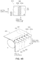
- FIG.4B is views illustrating a plurality of inspection units installed on a plane and an upper portion of a roll according to an exemplary embodiment of the present disclosure.
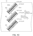
- FIG. 4C is a view illustrating directions in which magnetized poles are disposed according to an exemplary embodiment of the present disclosure.
- FIG.5A is views illustrating inspection units disposed an upper and lower portions of a steel plate according to an exemplary embodiment of the present disclosure.
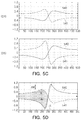
- FIGS.5B and 5C are diagrams illustrating output signals of the inspection units disposed on the upper and lower portions of the steel plate depending an positions of defects according to an exemplary embodiment of the present disclosure.
- FIGS. 5D and 5E are diagrams for describing a method for analyzing the positions of defects from the output signals of the inspection units disposed on the upper and lower portions of the steel plate.
- FIG. 3 is a configuration diagram of an inspection device according to an exemplary embodiment of the present disclosure.
- the inspection device may include a power supply unit 310 supplying power to a detector 320b, a plurality of inspection units (a single inspection unit 320 is illustrated in FIG. 3 ) arranged in a width direction of a steel plate 10, an amplifier 330 amplifying a leakage magnetic flux detected by the inspection unit 320, and a defect detection unit 340 detecting defects (hereinafter, referred to as "defects D") present in the steel plate 10 based on the leakage magnetic flux amplified by the amplifier 330.
- each of the plurality of inspection unit 320 may include a magnetizer 320a magnetizing the steel plate 10 in a predetermined direction and the detector 320b detecting the leakage magnetic flux due to the defects D in the steel plate 10.
- FIG. 4A is views illustrating an internal structure of a single inspection unit according to an exemplary embodiment of the present disclosure.
- one inspection unit 320 may include a permanent magnet PM and a yoke extended to both sides of the permanent magnet PM.
- a first magnetized pole 320c may be provided on one end of the yoke and a second magnetized pole 320d may be provided on the other end of the yoke.
- the permanent magnet PM a cylindrical permanent magnet, may be provided in the magnetizer 320a such that the permanent magnet PM may rotate about an axis of a cylinder extended in a length direction of the cylinder, and a magnitude of the magnetic flux induced in the yoke may be adjusted. That is, as the permanent magnet PM rotates about the axis of the cylinder extended in the length direction of the cylinder, a magnitude of magnetic flux formed between the first magnetized pole 320c and the second magnetized pole 320d may be varied.
- the first magnetized pole 320c and the second magnetized pole 320d may be disposed on an upper portion of the steel plate 10 in a direction inclined at a predetermined angle with respect to a rolling direction, and a description thereof will be provided below with reference to FIG. 4B .
- the detector 320b may be disposed between the first magnetized pole 320c and the second magnetized pole 320d in the length direction of the cylindrical permanent magnet PM, while being spaced apart from the first magnetized pole 320c and the second magnetized pole 320d by predetermined distances.
- the detector 320b is provided to detect the leakage magnetic flux due to an interior or surface defect of the steel plate 10 and may include a magnetic sensor or a hall sensor.
- the detector 320b may be an array formed of a plurality of hall elements and an interval L between adjacent hall sensors HS1 and HS2 may be 60 ⁇ m or less. According to the exemplary embodiment of the present disclosure, the interval between the adjacent hall sensors HS1 and HS2 may be significantly reduced, defect detection may be further precisely performed.
- the inspection units 320 may be provided in modular form and be individually detachable.
- the first magnetized pole 320c, the second magnetized pole 320d, the permanent magnet PM, and the detector 320b within each of the inspection units 320 may also be provided in modular form and the individual units may be separately detachable.
- the inspection device is provided in modular form as described above, maintenance and management efficiency of the inspection device may be increased.
- FIG. 4B is views illustrating a plurality of inspection units installed on a plane and an upper portion of a roll according to an exemplary embodiment of the present disclosure.
- FIG. 4C is a view illustrating directions in which magnetized poles are disposed according to an exemplary embodiment of the present disclosure.
- the defect inspection device for inspecting defects in the steel plate 10 may include a plurality of inspection units, and each of a plurality of inspection units 320 to 325 may be arranged in the width direction of the steel plate 10 and disposed in a direction inclined at a predetermined angle e with respect to a rolling direction of the steel plate 10.
- the plurality of inspection units 320 to 325 may be spaced apart from the steel plate 10 by a predetermine distance in a vertical direction.
- FIG. 4B illustrates a case in which only six inspection units 320 to 325 are provided, the case is merely provided for the convenience of explanation and it may be apparent to a person having ordinary skill in the art that the number of inspection units may be variously modified as needed.
- the plurality of inspection units 320 to 325 may be arranged in the width direction of the steel plate 10 on the upper portion of the steel plate 10 wound around a surface of a roll R, but may be disposed in a direction inclined at a predetermined angle e with respect to a rolling direction of the steel plate 10.
- FIG. 4C only illustrates three inspection units 320 to 322, the number of inspection units may be equal to the number of inspection units illustrated in FIG. 4B .
- the exemplary embodiment is explained based on a single inspection unit 320 with reference to FIG. 4C , the disposition directions may be applied to the remaining inspection units 321 and 322 in the same manner.
- the first magnetized pole 320c and the second magnetized pole 320d may have opposite polarities.
- the second magnetized pole 320d may be spaced apart from the first magnetized pole 320c by a predetermined distance and disposed to be parallel thereto, in a direction perpendicular to a direction in which the first magnetized pole 320c is inclined, and the first magnetized pole 320c and the second magnetized pole 320d may have the same length.
- an angle e at which the first magnetized pole 320c and the second magnetized pole 320d are inclined with respect to the rolling direction may be 45 degrees.
- the angle as described above is merely provided by way of example, it may be apparent to a person having ordinary skill in the art that the angle is modified as needed.
- two magnetized poles 320c and 320d configuring the magnetizer 320a have the same length, directions and degrees of intensity of magnetic flux formed in both ends of the magnetized poles 320c and 320d may be uniform, such that accurate defect detection may be enabled.
- power may be supplied to the detector 320b by the power supply unit 310 and the magnetic flux leakage caused by the defects D may be detected by the plurality of inspection units 320 to 325 arranged in the width direction of the steel plate 10.
- magnetic flux may be generated by the magnetizer 320a formed in a direction inclined at a predetermined angle with respect to the rolling direction, and the generated magnetic flux may pass through the steel plate 10.
- the detector 320b may detect a leakage magnetic flux due to the defects D present in the steel plate 10. The detected leakage magnetic flux may be transferred to the amplifier 330.
- the amplifier 330 may amplify the leakage magnetic flux detected in the inspection unit 320 at a predetermined ratio and then, transfer the amplified leakage magnetic flux to the defect detection unit 340.
- the defect detection unit 340 may detect the defects D in the steel plate 10 based on the leakage magnetic flux amplified by the amplifier 330.
- FIG. 5A is views illustrating inspection units disposed an upper and lower portions of a steel plate according to an exemplary embodiment of the present disclosure. Unlike FIG. 4A , a leakage magnetic flux may be detected by disposing inspection units 320 and 520 on both upper and lower portions of the steel plate 10, such that a surface defect and an interior defect may be separately detected or a position of the interior defect may be accurately determined.
- FIGS. 5B and 5C are diagrams illustrating output signals of the inspection units disposed on the upper and lower portions of the steel plate depending on positions of defects according to an exemplary embodiment of the present disclosure.
- an upper inspection unit 320 may be disposed on the upper portion of the steel plate 10 and a lower inspection unit 520 may be disposed on the lower portion of the steel plate 10, corresponding to the upper portion thereof.
- FIG. 5A illustrates a case in which a single upper inspection unit 320 and a single lower inspection unit 520 are disposed on the upper portion and the lower portion of the steel plate 10, respectively, a plurality of inspection units may be disposed an each of the upper and lower portions of the steel plate 10 as illustrated in FIG. 4B .
- reference numeral 530 indicates an enlarged view of defects present in a thickness direction of the steel plate 10, in an upper view of FIG. 5a and illustrates that the defects D may be present in various positions in a thickness direction 532 of the steel plate 10.
- D1 indicates the defect D present in or adjacent to an upper surface of the steel plate 10
- D2 indicates the defect D present in an upper interior portion
- D3 indicates the defect D present in a central portion of the steel plate 10
- D4 indicates the defect D present in a lower interior portion of the steel plate
- D5 indicates the defect D present in or adjacent to a lower surface of the steel plate 10.
- FIGS. 5B and 5C output signals from the upper inspection unit 320 and the lower inspection unit 520 are illustrated in FIG. 5B and FIG. 5C , respectively.
- reference numeral 540 indicates an output signal from the upper inspection unit 320
- reference numeral 541 indicates an output signal from the lower inspection unit 520.
- magnitudes and phases of the output signals from the upper inspection unit 320 and the lower inspection unit 520 are different depending on positions of the defects D1 to D5. That is, in the case of the defect D1 formed in or adjacent to the upper surface of the steel plate 10, it can be seen that a phase of the output signal 540 from the upper inspection unit 320 is opposite to that of the output signal 541 from the lower inspection unit 520, and a magnitude of the output signal 540 from the upper inspection unit 320 is higher than that of the output signal 541 from the lower inspection unit 520. Thus, it can be seen that the defect D is formed in or adjacent to the upper surface of the steel plate 10.
- the defect D3 formed in the central portion of the steel plate 10 it can be seen that the output signal 540 from the upper inspection unit 320 and the output signal 541 from the lower inspection unit 520 have the same degree of magnitude, but have opposite phases. Thus, it can be seen that the defect D is formed in the central portion of the steel plate 10.
- the position of the defect D may be analyzed by comparing the phase and the magnitude of the output signal 540 from the upper inspection unit 320 with those of the output signal 541 from the lower inspection unit 520.
- a defect position DP may be analyzed by calculating a defect function DF to which various factors are input, and a description thereof will be described with reference to FIGS. 5D and 5E .
- FIG. 5D is a diagram for describing factors provided to calculate the defect function DF from the output signal 540 from the upper inspection unit 320 and the output signal 541 from the lower inspection unit 520.
- ⁇ M denotes a difference in magnitudes of two output signals 540 and 541
- Al denotes an area of the output signal 541 from the lower inspection unit 520
- A2 denotes an area of the output signal 540 from the upper inspection unit 320
- S denotes a slope of a straight line formed by connecting a maximum value and a minimum value of the output signal.
- DF denotes a defect function
- ⁇ M denotes a difference in magnitudes of two output signals
- A denotes an area of the output signal
- S denotes a slope of a straight line formed by connecting a maximum value and a minimum value of the output signal
- Wf denotes a defect type (an circle, an oval, a line or the like)
- L denotes a value for compensating an interval between the detector and the steel plate.
- the defect function DF to which the factors such as ⁇ M, A, S, Wf, and L are input may be variously implemented, and it is not limited thereto in the present disclosure.
- the defect function DF to which only ⁇ M among the above-described factors such as ⁇ M, A, S, Wf, and L is input is calculated in FIG. 5E .
- a method of analyzing the defect position DP from the calculated defect function DF will be exemplified with reference to FIG. 5E . It is assumed that a thickness of the steel plate 10 is 1.2mm and a distance from a surface of the steel plate 10 to a center thereof is 0.6mm.
- the defect detection unit 340 of FIG. 3 may calculate the difference ⁇ M in magnitudes of the two output signals 540 and 541 depending on the defect position DP from the surface of the steel plate 10 to the center thereof and subsequently, may obtain a graph as illustrated in FIG. 5E .
- the defect position DP of 1 refers to a point distant from the upper surface of the steel plate 10 by 0.6mm (that is, the center of the steel plate) and the defect position DP of 0.1 refers to a point, the upper surface of the steel plate 10.
- the defect detection unit 340 of FIG. 3 may calculate the difference ⁇ M in magnitudes of the output signals 540 and 541 obtained from the upper inspection unit 320 and the lower inspection unit 520 and compare the calculated difference ⁇ M in magnitudes with the graph of FIG. 5E to thereby analyze the defect position DP.
- the defect position DP is 0.1 and accordingly, the defect D is located in the upper surface of the steel plate 10.
- the defect position DP is 1 and accordingly, the defect D is located in the point (the center) distant from the upper surface of the steel plate 10 by 0.6mm.
- the defect D may be present in a certain point between the upper surface of the steel plate 10 and the center thereof (the point distant from the upper surface of the steel plate 10 by 0.6mm)
- the inspection units may be disposed on both upper and lower portions of the steel plate to detect a leakage magnetic flux, such that a surface defect and an interior defect may be separately detected and a position of the interior defect may be accurately determined.
Landscapes
- Chemical & Material Sciences (AREA)
- Chemical Kinetics & Catalysis (AREA)
- Electrochemistry (AREA)
- Physics & Mathematics (AREA)
- Health & Medical Sciences (AREA)
- Life Sciences & Earth Sciences (AREA)
- Analytical Chemistry (AREA)
- Biochemistry (AREA)
- General Health & Medical Sciences (AREA)
- General Physics & Mathematics (AREA)
- Immunology (AREA)
- Pathology (AREA)
- Investigating Or Analyzing Materials By The Use Of Magnetic Means (AREA)
Abstract
Description
- The present disclosure relates to a device for inspecting defects present in an interior portion or a surface of a steel plate using a leakage magnetic flux.
- Technologies for detecting defects in a steel plate may include an ultrasonic test, a magnetic flux leakage inspection, a magnetic particle inspection, an eddy-current inspection, an optical inspection method and the like.
- Among these, a magnetic flux leakage inspection is a scheme of detecting a portion of magnetic flux leaked to the outside of a steel plate due to defects present in a steel plate when the steel plate is magnetized in a certain direction, using a magnetic sensor or a hall sensor. Such a magnetic flux leakage inspection may have superior performance in terms of the detection of crack defects occurring in a surface or below a surface layer of a ferromagnetic metal, and an example of an inspection device using the magnetic flux leakage described above is disclosed in Cited Document (Korean Patent Laid-Open Publication No.
2010-0076838 - Referring to
FIG. 1 in connection with Korean Patent Laid-Open Publication No.2010-0076838 magnetizer 120 may be disposed an on upper portion of asteel plate 10 wound around aroll 110.Electromagnetic poles magnetizer 120 and acoil 122 is wound an an upper region of themagnetizer 120. Here, in a case in which currents flow in theelectromagnetic poles coil 122 in opposite directions, thesteel plate 10 may be magnetized in a direction from theelectromagnetic pole 121a having N-polarity to theelectromagnetic pole 121b having S-polarity. In this case, a leakage magnetic flux may be sensed by asensor 131 disposed between theelectromagnetic poles steel plate 10 may be detected. Meanwhile, theelectromagnetic poles steel plate 10 comes into contact with theroll 110, in a spiral manner. - However, according to the Cited Document, the following limitations are present.
- First, as illustrated in
FIG. 2 , accurate detection of defects may be difficult due to a non-detection region R1 in which magnetic flux is unable to be detected. In magnetic flux formed in ends of theelectromagnetic pole 121a having N-polarity and theelectromagnetic pole 121b having S-polarity, directions and degrees of intensity thereof may not be uniformly formed (seereference numeral 201 and R2). - Second, as illustrated in
FIG. 1 , themagnetizer 120 may have an integrated structure in which a plurality of theelectromagnetic poles electromagnetic poles sensor 131, leading to difficulties in terms of maintenance and management. - Third, since defects present in a surface and an interior portion of the
steel plate 10 may be simultaneously detected, it may be difficult to separately detect a surface defect and an interior defect or accurately determining a position of the interior defect may be unfeasible. - An aspect of the present disclosure provides a device for inspecting defects in a steel plate, the device being capable of accurately detecting defects in surfaces or in interior portions of the steel plate.
- An aspect of the present disclosure also provides a device for inspecting defects in a steel plate, the device allowing for efficient maintenance and management thereof.
- An aspect of the present disclosure also provides a device for inspecting defects in a steel plate, the device being capable of separately detecting a surface defect and an interior defect or accurately determining a position of the interior defect.
- According to an aspect of the present disclosure, a defect inspection device for inspecting defects in a steel plate may include: a plurality of inspection units arranged in a width direction of the steel plate, wherein each of the plurality of inspection units includes a magnetizer including a first magnetized pole and a second magnetized pole corresponding to each other, and generating magnetic flux for magnetizing the steel plate in a direction inclined at a predetermined angle with respect to a rolling direction of the steel plate; and a detector detecting a leakage magnetic flux leaked due to defects present in an interior portion or a surface of the steel plate, using the magnetic flux generated by the magnetizer.
- According to an aspect of the present disclosure, the second magnetized pole may be spaced apart from the first magnetized pole by a predetermined distance and disposed to be parallel to the first magnetized pole, in a direction perpendicular to a direction in which the first magnetized pole is inclined, and the first magnetized pole and the second magnetized pole may have the same length.
- According to an aspect of the present disclosure, the first magnetized pole and the second magnetized pole may be inclined at an angle of 45 degrees with respect to the rolling direction.
- According to an aspect of the present disclosure, the plurality of inspection units may be provided in modular form such that the inspection units are individually detachable.
- According to an aspect of the present disclosure, the magnetizer may have a permanent magnet and a yoke extended to both sides of the permanent magnet, and the first magnetized pole may be provided on one end of the yoke and a second magnetized pole may be provided on the other end of the yoke.
- According to an aspect of the present disclosure, the permanent magnet may be a cylindrical permanent magnet.
- The cylindrical permanent magnet may be provided in the magnetizer such that the cylindrical permanent magnet rotates about an axis of a cylinder extended in a length direction of the cylinder, and a magnitude of the magnetic flux induced in the yoke may be adjustable.
- According to an aspect of the present disclosure, the plurality of inspection units may include upper inspection units disposed an an upper portion of the steel plate; and lower inspection units disposed an a lower portion of the steel plate.
- According to an aspect of the present disclosure, the defect inspection device may further include a defect analyzer analyzing a defect position in a thickness direction of the steel plate, based on a phase and a magnitude of a signal measured by each of the upper inspection units and lower inspection units.
- According to an aspect of the present disclosure, the detector may include a plurality of hall sensors, an interval between the hall sensors adjacent to each other being 60µm or less.
- According to an aspect of the present disclosure, in the plurality of inspection units, the first and second magnetized poles may be disposed such that adjacent magnetized poles in the inspection units adjacent to each other are identical to each other.
- According to exemplary embodiments of the present disclosure, two magnetized poles configuring a magnetizer have the same length, such that accurate defect detection may be enabled.
- According to exemplary embodiments of the present disclosure, a plurality of inspection units are provided in modular form such that the inspection units are individually detachable. Thus, maintenance and management efficiency of an inspection device may be increased.
- According to exemplary embodiments of the present disclosure, the inspection units are disposed on both upper and lower portions of the steel plate to detect a leakage magnetic flux, a surface defect and an interior defect may be separately detected and a position of the interior defect may be accurately determined.
-
FIG. 1 is a view illustrating a structure of an inspection device according to the related art. -
FIG. 2 is views illustrating the inspection device ofFIG. 1 when viewed from the above, in order to describe limitations of the related art. -
FIG.3 is a configuration diagram of an inspection device according to an exemplary embodiment of the present disclosure. -
FIG.4A is views illustrating an internal structure of an inspection unit according to an exemplary embodiment of the present disclosure. -
FIG.4B is views illustrating a plurality of inspection units installed on a plane and an upper portion of a roll according to an exemplary embodiment of the present disclosure. -
FIG. 4C is a view illustrating directions in which magnetized poles are disposed according to an exemplary embodiment of the present disclosure. -
FIG.5A is views illustrating inspection units disposed an upper and lower portions of a steel plate according to an exemplary embodiment of the present disclosure. -
FIGS.5B and5C are diagrams illustrating output signals of the inspection units disposed on the upper and lower portions of the steel plate depending an positions of defects according to an exemplary embodiment of the present disclosure. -
FIGS. 5D and5E are diagrams for describing a method for analyzing the positions of defects from the output signals of the inspection units disposed on the upper and lower portions of the steel plate. - Hereinafter, exemplary embodiments of the present disclosure will now be described in detail with reference to the accompanying drawings. Exemplary embodiments of the present disclosure may, however, be exemplified in many different forms and should not be construed as being limited to the specific embodiments set forth herein. In the drawings, the shapes and dimensions of elements may be exaggerated for clarity, and the same reference numerals will be used throughout to designate the same or like elements.
-
FIG. 3 is a configuration diagram of an inspection device according to an exemplary embodiment of the present disclosure. The inspection device according to an exemplary embodiment of the present disclosure may include apower supply unit 310 supplying power to adetector 320b, a plurality of inspection units (asingle inspection unit 320 is illustrated inFIG. 3 ) arranged in a width direction of asteel plate 10, anamplifier 330 amplifying a leakage magnetic flux detected by theinspection unit 320, and adefect detection unit 340 detecting defects (hereinafter, referred to as "defects D") present in thesteel plate 10 based on the leakage magnetic flux amplified by theamplifier 330. Meanwhile, each of the plurality ofinspection unit 320 may include amagnetizer 320a magnetizing thesteel plate 10 in a predetermined direction and thedetector 320b detecting the leakage magnetic flux due to the defects D in thesteel plate 10. - Hereinafter, the inspection unit will be described in detail.
-
FIG. 4A is views illustrating an internal structure of a single inspection unit according to an exemplary embodiment of the present disclosure. - As illustrated in
FIG. 4A , oneinspection unit 320 may include a permanent magnet PM and a yoke extended to both sides of the permanent magnet PM. A firstmagnetized pole 320c may be provided on one end of the yoke and a secondmagnetized pole 320d may be provided on the other end of the yoke. The permanent magnet PM, a cylindrical permanent magnet, may be provided in themagnetizer 320a such that the permanent magnet PM may rotate about an axis of a cylinder extended in a length direction of the cylinder, and a magnitude of the magnetic flux induced in the yoke may be adjusted. That is, as the permanent magnet PM rotates about the axis of the cylinder extended in the length direction of the cylinder, a magnitude of magnetic flux formed between the firstmagnetized pole 320c and the secondmagnetized pole 320d may be varied. - By way of example, in a case in which N-pole and S-pole of the permanent magnet PM are vertically disposed, the lowest magnitude of magnetic flux is formed between the first
magnetized pole 320c and the secondmagnetized pole 320d. In a case in which N-pole and S-pole of the permanent magnet PM are horizontally disposed, the highest magnitude of magnetic flux is formed between the firstmagnetized pole 320c and the secondmagnetized pole 320d. In addition, the firstmagnetized pole 320c and the secondmagnetized pole 320d may be disposed on an upper portion of thesteel plate 10 in a direction inclined at a predetermined angle with respect to a rolling direction, and a description thereof will be provided below with reference toFIG. 4B . - Further, the
detector 320b may be disposed between the firstmagnetized pole 320c and the secondmagnetized pole 320d in the length direction of the cylindrical permanent magnet PM, while being spaced apart from the firstmagnetized pole 320c and the secondmagnetized pole 320d by predetermined distances. Thedetector 320b is provided to detect the leakage magnetic flux due to an interior or surface defect of thesteel plate 10 and may include a magnetic sensor or a hall sensor. Further, thedetector 320b may be an array formed of a plurality of hall elements and an interval L between adjacent hall sensors HS1 and HS2 may be 60µm or less. According to the exemplary embodiment of the present disclosure, the interval between the adjacent hall sensors HS1 and HS2 may be significantly reduced, defect detection may be further precisely performed. - Moreover, according to the exemplary embodiment of the present disclosure, the
inspection units 320 may be provided in modular form and be individually detachable. In addition, the firstmagnetized pole 320c, the secondmagnetized pole 320d, the permanent magnet PM, and thedetector 320b within each of theinspection units 320 may also be provided in modular form and the individual units may be separately detachable. The inspection device is provided in modular form as described above, maintenance and management efficiency of the inspection device may be increased. - Meanwhile,
FIG. 4B is views illustrating a plurality of inspection units installed on a plane and an upper portion of a roll according to an exemplary embodiment of the present disclosure.FIG. 4C is a view illustrating directions in which magnetized poles are disposed according to an exemplary embodiment of the present disclosure. - According to the exemplary embodiment of the present disclosure, as illustrated in
reference numeral 410 ofFIG. 4B , the defect inspection device for inspecting defects in the steel plate 10 (as described in detail with reference toFIG. 4A ) may include a plurality of inspection units, and each of a plurality ofinspection units 320 to 325 may be arranged in the width direction of thesteel plate 10 and disposed in a direction inclined at a predetermined angle e with respect to a rolling direction of thesteel plate 10. The plurality ofinspection units 320 to 325 may be spaced apart from thesteel plate 10 by a predetermine distance in a vertical direction. AlthoughFIG. 4B illustrates a case in which only sixinspection units 320 to 325 are provided, the case is merely provided for the convenience of explanation and it may be apparent to a person having ordinary skill in the art that the number of inspection units may be variously modified as needed. - Furthermore, depending on embodiments, as illustrated in
reference numeral 420 ofFIG. 4B , the plurality ofinspection units 320 to 325 may be arranged in the width direction of thesteel plate 10 on the upper portion of thesteel plate 10 wound around a surface of a roll R, but may be disposed in a direction inclined at a predetermined angle e with respect to a rolling direction of thesteel plate 10. - Hereinafter, directions in which magnetized poles within the inspection units are disposed will be described in detail with reference to
FIG. 4C . For the understanding of the present disclosure, althoughFIG. 4C only illustrates threeinspection units 320 to 322, the number of inspection units may be equal to the number of inspection units illustrated inFIG. 4B . In addition, for the understanding of the present disclosure, although the exemplary embodiment is explained based on asingle inspection unit 320 with reference toFIG. 4C , the disposition directions may be applied to the remaininginspection units - As illustrated in
FIG. 4C , the firstmagnetized pole 320c and the secondmagnetized pole 320d may have opposite polarities. The secondmagnetized pole 320d may be spaced apart from the firstmagnetized pole 320c by a predetermined distance and disposed to be parallel thereto, in a direction perpendicular to a direction in which the firstmagnetized pole 320c is inclined, and the firstmagnetized pole 320c and the secondmagnetized pole 320d may have the same length. Here, an angle e at which the firstmagnetized pole 320c and the secondmagnetized pole 320d are inclined with respect to the rolling direction may be 45 degrees. The angle as described above is merely provided by way of example, it may be apparent to a person having ordinary skill in the art that the angle is modified as needed. - As described above, according to an exemplary embodiment of the present disclosure, two
magnetized poles magnetized poles - An operational principle of the inspection device according to the exemplary embodiment as described above will be explained.
- Referring to
FIGS. 3 through 4C , power may be supplied to thedetector 320b by thepower supply unit 310 and the magnetic flux leakage caused by the defects D may be detected by the plurality ofinspection units 320 to 325 arranged in the width direction of thesteel plate 10. By way of example, in thesingle inspection unit 320, magnetic flux may be generated by themagnetizer 320a formed in a direction inclined at a predetermined angle with respect to the rolling direction, and the generated magnetic flux may pass through thesteel plate 10. In this case, thedetector 320b may detect a leakage magnetic flux due to the defects D present in thesteel plate 10. The detected leakage magnetic flux may be transferred to theamplifier 330. - Next, the
amplifier 330 may amplify the leakage magnetic flux detected in theinspection unit 320 at a predetermined ratio and then, transfer the amplified leakage magnetic flux to thedefect detection unit 340. Finally, thedefect detection unit 340 may detect the defects D in thesteel plate 10 based on the leakage magnetic flux amplified by theamplifier 330. -
FIG. 5A is views illustrating inspection units disposed an upper and lower portions of a steel plate according to an exemplary embodiment of the present disclosure. UnlikeFIG. 4A , a leakage magnetic flux may be detected by disposinginspection units steel plate 10, such that a surface defect and an interior defect may be separately detected or a position of the interior defect may be accurately determined.FIGS. 5B and5C are diagrams illustrating output signals of the inspection units disposed on the upper and lower portions of the steel plate depending on positions of defects according to an exemplary embodiment of the present disclosure. - Hereinafter, an inspection device and an operational principle thereof according to an exemplary embodiment will be described.
- Referring to
FIG. 5A , anupper inspection unit 320 may be disposed on the upper portion of thesteel plate 10 and alower inspection unit 520 may be disposed on the lower portion of thesteel plate 10, corresponding to the upper portion thereof. For the understanding of the present disclosure, whileFIG. 5A illustrates a case in which a singleupper inspection unit 320 and a singlelower inspection unit 520 are disposed on the upper portion and the lower portion of thesteel plate 10, respectively, a plurality of inspection units may be disposed an each of the upper and lower portions of thesteel plate 10 as illustrated inFIG. 4B . - Meanwhile,
reference numeral 530 indicates an enlarged view of defects present in a thickness direction of thesteel plate 10, in an upper view ofFIG. 5a and illustrates that the defects D may be present in various positions in athickness direction 532 of thesteel plate 10. For example, as illustrated inreference numeral 531, D1 indicates the defect D present in or adjacent to an upper surface of thesteel plate 10, D2 indicates the defect D present in an upper interior portion, D3 indicates the defect D present in a central portion of thesteel plate 10, D4 indicates the defect D present in a lower interior portion of thesteel plate 10, and D5 indicates the defect D present in or adjacent to a lower surface of thesteel plate 10. - With regard to the respective defects D1 to D5, output signals from the
upper inspection unit 320 and thelower inspection unit 520 are illustrated inFIG. 5B andFIG. 5C , respectively. InFIGS. 5B and5C ,reference numeral 540 indicates an output signal from theupper inspection unit 320 andreference numeral 541 indicates an output signal from thelower inspection unit 520. - As illustrated in
FIGS. 5B and5C , magnitudes and phases of the output signals from theupper inspection unit 320 and thelower inspection unit 520 are different depending on positions of the defects D1 to D5. That is, in the case of the defect D1 formed in or adjacent to the upper surface of thesteel plate 10, it can be seen that a phase of theoutput signal 540 from theupper inspection unit 320 is opposite to that of theoutput signal 541 from thelower inspection unit 520, and a magnitude of theoutput signal 540 from theupper inspection unit 320 is higher than that of theoutput signal 541 from thelower inspection unit 520. Thus, it can be seen that the defect D is formed in or adjacent to the upper surface of thesteel plate 10. - On the contrary, in the case of the defect D5 formed in or adjacent to the lower surface of the
steel plate 10, it can be seen that a phase of theoutput signal 541 from thelower inspection unit 520 is opposite to that of theoutput signal 540 from theupper inspection unit 320, and a magnitude of theoutput signal 541 from thelower inspection unit 520 is higher than that of theoutput signal 540 from theupper inspection unit 320. Thus, it can be seen that the defect D is formed in or adjacent to the lower surface of thesteel plate 10. - On the other hand, in the case of the defect D3 formed in the central portion of the
steel plate 10, it can be seen that theoutput signal 540 from theupper inspection unit 320 and theoutput signal 541 from thelower inspection unit 520 have the same degree of magnitude, but have opposite phases. Thus, it can be seen that the defect D is formed in the central portion of thesteel plate 10. - As described above, the position of the defect D may be analyzed by comparing the phase and the magnitude of the
output signal 540 from theupper inspection unit 320 with those of theoutput signal 541 from thelower inspection unit 520. - In addition to the graphical method described above, a defect position DP may be analyzed by calculating a defect function DF to which various factors are input, and a description thereof will be described with reference to
FIGS. 5D and5E . -
FIG. 5D is a diagram for describing factors provided to calculate the defect function DF from theoutput signal 540 from theupper inspection unit 320 and theoutput signal 541 from thelower inspection unit 520. - In
FIG. 5D , ΔM denotes a difference in magnitudes of twooutput signals output signal 541 from thelower inspection unit 520, A2 denotes an area of theoutput signal 540 from theupper inspection unit 320, and S denotes a slope of a straight line formed by connecting a maximum value and a minimum value of the output signal. - According to an exemplary embodiment of the present disclosure, the defect function DF may be calculated according to the following
mathematical formula 1, based on several further factors in addition to the various factors described above.
- Here, DF denotes a defect function, ΔM denotes a difference in magnitudes of two output signals, A denotes an area of the output signal, S denotes a slope of a straight line formed by connecting a maximum value and a minimum value of the output signal, Wf denotes a defect type (an circle, an oval, a line or the like), and L denotes a value for compensating an interval between the detector and the steel plate.
- The defect function DF to which the factors such as ΔM, A, S, Wf, and L are input may be variously implemented, and it is not limited thereto in the present disclosure.
- However, hereinafter, the defect function DF to which only ΔM among the above-described factors such as ΔM, A, S, Wf, and L is input is calculated in
FIG. 5E . A method of analyzing the defect position DP from the calculated defect function DF will be exemplified with reference toFIG. 5E . It is assumed that a thickness of thesteel plate 10 is 1.2mm and a distance from a surface of thesteel plate 10 to a center thereof is 0.6mm. - First, the
defect detection unit 340 ofFIG. 3 may calculate the difference ΔM in magnitudes of the twooutput signals steel plate 10 to the center thereof and subsequently, may obtain a graph as illustrated inFIG. 5E . Here, the defect position DP of 1 refers to a point distant from the upper surface of thesteel plate 10 by 0.6mm (that is, the center of the steel plate) and the defect position DP of 0.1 refers to a point, the upper surface of thesteel plate 10. - Thereafter, the
defect detection unit 340 ofFIG. 3 may calculate the difference ΔM in magnitudes of the output signals 540 and 541 obtained from theupper inspection unit 320 and thelower inspection unit 520 and compare the calculated difference ΔM in magnitudes with the graph ofFIG. 5E to thereby analyze the defect position DP. - For example, in
FIG. 5E , in a case in which the difference ΔM (that is, the defect function DF) in magnitudes of the two output signals is 1 (when ΔM is 1, since the difference ΔM in magnitudes of the two output signals is the greatest, it may be previously confirmed that the defect D may be present in the upper surface of the steel plate 10), it can be confirmed that the defect position DP is 0.1 and accordingly, the defect D is located in the upper surface of thesteel plate 10. - As another example, in a case in which the difference ΔM (that is, the defect function DF) in magnitudes of the two output signals is 0 (when ΔM is 0, since the difference ΔM in magnitudes of the two output signals is the lowest, it may be previously confirmed that the defect D may be present in the center of the steel plate 10), it can be confirmed that the defect position DP is 1 and accordingly, the defect D is located in the point (the center) distant from the upper surface of the
steel plate 10 by 0.6mm. - In a case in which the difference ΔM in magnitudes of the two output signals ranges from 1 to 0, it may be analyzed that the defect D may be present in a certain point between the upper surface of the
steel plate 10 and the center thereof (the point distant from the upper surface of thesteel plate 10 by 0.6mm) - As set forth above, according to exemplary embodiments of the present disclosure, the inspection units may be disposed on both upper and lower portions of the steel plate to detect a leakage magnetic flux, such that a surface defect and an interior defect may be separately detected and a position of the interior defect may be accurately determined.
- While the present disclosure has been shown and described in connection with the embodiments and the drawings, it will be apparent to those skilled in the art that modifications and variations can be made without departing from the Spirit and scope of the disclosure as defined by the appended claims. Independent aspects of the invention, which might be claimed in combination with or in replacement of the subject matter of
claim 1 are the following: - Aspect 1: A defect inspection device for inspecting defects in a steel plate, the defect inspection device comprising:
- a plurality of inspection units arranged in a width direction of the steel plate,
- wherein each of the plurality of inspection units includes:
- a magnetizer including a first magnetized pole and a second magnetized pole corresponding to each other, and generating magnetic flux for magnetizing the steel plate in a direction inclined at a predetermined angle with respect to a rolling direction of the steel plate; and
- a detector detecting a leakage magnetic flux leaked due to defects present in an interior portion or a surface of the steel plate, using the magnetic flux generated by the magnetizer.
- Aspect 2: The defect inspection device of
aspect 1, wherein the second magnetized pole is spaced apart from the first magnetized pole by a predetermined distance and disposed to be parallel to the first magnetized pole, in a direction perpendicular to a direction in which the first magnetized pole is inclined. - Aspect 3: The defect inspection device of aspect 2, wherein the first magnetized pole and the second magnetized pole have the same length.
- Aspect 4: The defect inspection device of
aspect 1, wherein the first magnetized pole and the second magnetized pole are inclined at an angle of 45 degrees with respect to the rolling direction. - Aspect 5: The defect inspection device of
aspect 1, wherein the plurality of inspection units are provided in modular form such that the inspection units are individually detachable. - Aspect 6: The defect inspection device of
aspect 1, wherein the magnetizer has a permanent magnet and a yoke extended to both sides of the permanent magnet, and
the first magnetized pole is provided on one end of the yoke and a second magnetized pole is provided on the other end of the yoke. - Aspect 7: The defect inspection device of aspect 6, wherein the permanent magnet is a cylindrical permanent magnet.
- Aspect 8: The defect inspection device of aspect 7, wherein the cylindrical permanent magnet is provided in the magnetizer such that the cylindrical permanent magnet rotates about an axis of a cylinder extended in a length direction of the cylinder, and
a magnitude of the magnetic flux induced in the yoke is adjustable. - Aspect 9: The defect inspection device of
aspect 1, wherein the plurality of inspection units include:- upper inspection units disposed on an upper portion of the steel plate; and
- lower inspection units disposed on a lower portion of the steel plate.
- Aspect 10: The defect inspection device of aspect 9, further comprising: a defect analyzer analyzing a defect position in a thickness direction of the steel plate, based on a phase and a magnitude of a signal measured by each of the upper inspection units and lower inspection units.
- Aspect 11: The defect inspection device of
aspect 1, wherein the detector includes a plurality of hall sensors, an interval between the hall sensors adjacent to each other being 60 µm or less.
Claims (1)
- A defect inspection device for inspecting defects in a steel plate (10) rolling in a first direction, the defect inspection device comprising:a plurality of inspection units arranged in a second width direction perpendicular to the first direction of the steel plate (10), each of the plurality of inspection units having an upper inspection unit (320) disposable on an upper portion of the steel plate (10) and a lower inspection unit (520) disposable on a lower portion of the steel plate (10), wherein each of upper inspection units (320) and lower inspection units (520) comprises:a magnetizer (120) including a first magnetized pole (320c) anda second magnetized pole (320d) corresponding to each other; anda detector (320b) configured for detecting a leakage magnetic flux leaked due to defects present in an interior portion or a surface of the steel plate
(10), using the magnetic flux generated by the magnetizer (120),wherein the defect inspection device further comprises a defect detection unit (320) configured for detecting a defect position in a thickness direction of the steel plate (10), based on a phase and a magnitude of a signal measured by the upper inspection unit (320) and the lower inspection unit (520) of each of the plurality of inspection units, the defect detection unit (340) detecting defects using a defect function DF calculated according to Formula 1,
Applications Claiming Priority (3)
| Application Number | Priority Date | Filing Date | Title |
|---|---|---|---|
| KR1020110135319A KR101309966B1 (en) | 2011-12-15 | 2011-12-15 | Apparatus for detecting defect of steel plate |
| EP12857074.4A EP2796869A4 (en) | 2011-12-15 | 2012-11-30 | DEVICE FOR INSPECTING STEEL PLATE DEFECTS |
| PCT/KR2012/010307 WO2013089373A1 (en) | 2011-12-15 | 2012-11-30 | Defect inspection device of steel plate |
Related Parent Applications (1)
| Application Number | Title | Priority Date | Filing Date |
|---|---|---|---|
| EP12857074.4A Division EP2796869A4 (en) | 2011-12-15 | 2012-11-30 | DEVICE FOR INSPECTING STEEL PLATE DEFECTS |
Publications (1)
| Publication Number | Publication Date |
|---|---|
| EP3851846A1 true EP3851846A1 (en) | 2021-07-21 |
Family
ID=48612773
Family Applications (2)
| Application Number | Title | Priority Date | Filing Date |
|---|---|---|---|
| EP12857074.4A Withdrawn EP2796869A4 (en) | 2011-12-15 | 2012-11-30 | DEVICE FOR INSPECTING STEEL PLATE DEFECTS |
| EP21161512.5A Pending EP3851846A1 (en) | 2011-12-15 | 2012-11-30 | Defect inspection device for steel plate |
Family Applications Before (1)
| Application Number | Title | Priority Date | Filing Date |
|---|---|---|---|
| EP12857074.4A Withdrawn EP2796869A4 (en) | 2011-12-15 | 2012-11-30 | DEVICE FOR INSPECTING STEEL PLATE DEFECTS |
Country Status (6)
| Country | Link |
|---|---|
| US (1) | US9417212B2 (en) |
| EP (2) | EP2796869A4 (en) |
| JP (1) | JP6051229B2 (en) |
| KR (1) | KR101309966B1 (en) |
| CN (1) | CN103998924B (en) |
| WO (1) | WO2013089373A1 (en) |
Families Citing this family (8)
| Publication number | Priority date | Publication date | Assignee | Title |
|---|---|---|---|---|
| KR101482347B1 (en) | 2012-12-27 | 2015-01-13 | 주식회사 포스코 | Apparatus and method of detecting inner defect of steel plate |
| KR101657745B1 (en) | 2013-12-11 | 2016-09-19 | 주식회사 포스코 | Apparatus and method of detecting defect of steel plate |
| CN105572227B (en) * | 2016-03-16 | 2018-02-27 | 武汉优凯检测技术有限公司 | One kind probe underneath type non-contact detecting steel plate automatic flaw detection device |
| CN109283243A (en) * | 2017-07-19 | 2019-01-29 | 迅得机械股份有限公司 | Flexible board marking system and method |
| WO2019077778A1 (en) * | 2017-10-20 | 2019-04-25 | 国立大学法人 岡山大学 | Eddy-current flaw testing method and eddy-current flaw testing device |
| CN109781832A (en) * | 2019-03-19 | 2019-05-21 | 哈尔滨工业大学(深圳) | A kind of method and excitation unit of coated steel strip damage check |
| KR102589404B1 (en) * | 2019-04-24 | 2023-10-16 | 제이에프이 스틸 가부시키가이샤 | Leakage flux detection device |
| DE102019004240B4 (en) * | 2019-06-18 | 2024-04-25 | Mike Pfennig | Apparatus for testing steel wire ropes and method for its use |
Citations (4)
| Publication number | Priority date | Publication date | Assignee | Title |
|---|---|---|---|---|
| JPS57108656A (en) * | 1980-12-26 | 1982-07-06 | Kawasaki Steel Corp | Detecting method of internal defect in thin steel plate |
| JPH09274016A (en) * | 1996-04-05 | 1997-10-21 | Nkk Corp | Method and apparatus for flaw detection of magnetic metal body |
| KR20100076838A (en) | 2008-12-26 | 2010-07-06 | 주식회사 포스코 | Defect inspection apparatus and method of steel sheet |
| US20110040499A1 (en) * | 2008-03-31 | 2011-02-17 | Jfe Steel Corporation | Apparatus for detecting periodic defect and method therefor |
Family Cites Families (12)
| Publication number | Priority date | Publication date | Assignee | Title |
|---|---|---|---|---|
| JPH05322851A (en) * | 1992-05-19 | 1993-12-07 | Syst Hightech:Kk | Thin-steel band magnetic flaw detector by inclined magnetic field |
| JP2769534B2 (en) * | 1992-05-19 | 1998-06-25 | 株式会社システムハイテック | Array structure of magnetic sensors in thin steel strip magnetic testing equipment |
| US6057684A (en) * | 1995-10-31 | 2000-05-02 | Yoshihiro Murakami | Magnetic flaw detection apparatus using an E-shaped magnetic sensor and high-pass filter |
| JPH09304345A (en) | 1996-05-10 | 1997-11-28 | Nippon Steel Corp | Magnetic head device |
| WO2002004937A1 (en) | 2000-07-12 | 2002-01-17 | Nkk Corporation | Magnetic leakage flux flaw detection method and manufacturing method of hot rolled steel plate using the same |
| JP2007322176A (en) | 2006-05-30 | 2007-12-13 | Toshiba Corp | Magnetic flaw detector and its leakage magnetic sensor |
| CN100427947C (en) * | 2006-06-16 | 2008-10-22 | 清华大学 | Magnetic flux leakage detection method for large-area steel plate defects |
| JP2010048624A (en) | 2008-08-20 | 2010-03-04 | Sanshiro Kimoto | Low-frequency electromagnetic induction type defect measuring apparatus |
| JP2011007565A (en) | 2009-06-24 | 2011-01-13 | Jfe Engineering Corp | Leakage flux flaw detector |
| KR101085563B1 (en) | 2009-09-04 | 2011-11-25 | 조선대학교산학협력단 | Inclusion apparatus of cold rolled steel plate using magnetic sensor |
| JP5544962B2 (en) | 2010-03-19 | 2014-07-09 | Jfeスチール株式会社 | Magnetic flux leakage flaw detection method and magnetic flux leakage inspection device |
| US20110234212A1 (en) * | 2010-03-29 | 2011-09-29 | Benoit Lepage | Magnetic flux leakage inspection device |
-
2011
- 2011-12-15 KR KR1020110135319A patent/KR101309966B1/en active Active
-
2012
- 2012-11-30 WO PCT/KR2012/010307 patent/WO2013089373A1/en not_active Ceased
- 2012-11-30 US US14/365,299 patent/US9417212B2/en active Active
- 2012-11-30 CN CN201280062114.8A patent/CN103998924B/en active Active
- 2012-11-30 EP EP12857074.4A patent/EP2796869A4/en not_active Withdrawn
- 2012-11-30 JP JP2014547086A patent/JP6051229B2/en active Active
- 2012-11-30 EP EP21161512.5A patent/EP3851846A1/en active Pending
Patent Citations (4)
| Publication number | Priority date | Publication date | Assignee | Title |
|---|---|---|---|---|
| JPS57108656A (en) * | 1980-12-26 | 1982-07-06 | Kawasaki Steel Corp | Detecting method of internal defect in thin steel plate |
| JPH09274016A (en) * | 1996-04-05 | 1997-10-21 | Nkk Corp | Method and apparatus for flaw detection of magnetic metal body |
| US20110040499A1 (en) * | 2008-03-31 | 2011-02-17 | Jfe Steel Corporation | Apparatus for detecting periodic defect and method therefor |
| KR20100076838A (en) | 2008-12-26 | 2010-07-06 | 주식회사 포스코 | Defect inspection apparatus and method of steel sheet |
Also Published As
| Publication number | Publication date |
|---|---|
| CN103998924A (en) | 2014-08-20 |
| WO2013089373A1 (en) | 2013-06-20 |
| JP2015500498A (en) | 2015-01-05 |
| CN103998924B (en) | 2017-05-24 |
| KR101309966B1 (en) | 2013-09-17 |
| US20140347041A1 (en) | 2014-11-27 |
| KR20130068295A (en) | 2013-06-26 |
| EP2796869A1 (en) | 2014-10-29 |
| US9417212B2 (en) | 2016-08-16 |
| EP2796869A4 (en) | 2015-12-23 |
| JP6051229B2 (en) | 2016-12-27 |
Similar Documents
| Publication | Publication Date | Title |
|---|---|---|
| EP2796869A1 (en) | Defect inspection device of steel plate | |
| US10539535B2 (en) | Defect measurement method, defect measurement device, and testing probe | |
| EP2940464A1 (en) | Apparatus and method for detecting inner defects of steel plate | |
| JP6189870B2 (en) | Penetration coil configuration, test apparatus having penetration coil configuration, and test method | |
| KR20150048141A (en) | Eddy current flaw detection probe and eddy current flaw inspection apparatus | |
| CN113740413B (en) | A steel plate delamination defect detection method and system based on magnetic permeability disturbance measurement | |
| JP2006220610A (en) | Defect detection device | |
| KR20190089027A (en) | Damage evaluation method and damage evaluation device of magnetic cord | |
| KR20140117983A (en) | Apparatus for detecting defect of rolled coil | |
| CN113728226B (en) | Magnetic flux leakage detection device | |
| JP5140214B2 (en) | Rotating eddy current flaw detection probe | |
| JP4175181B2 (en) | Magnetic flux leakage flaw detector | |
| JP4192708B2 (en) | Magnetic sensor | |
| JP4842922B2 (en) | Electromagnetic ultrasonic probe | |
| EP3081932B1 (en) | Apparatus and method of inspecting defect of steel plate | |
| RU109863U1 (en) | MAGNETIC SYSTEM OF AN IN-TUBE DEFECTOSCOPE WITH TRANSVERSE MAGNETIZATION | |
| KR101482346B1 (en) | Apparatus and method of detecting surface defect of steel plate | |
| RU2210786C2 (en) | Permanent magnet coercimeter | |
| JP2007163263A (en) | Eddy current flaw detection sensor | |
| KR20160049115A (en) | Calibration module of magnetic sensor and apparatus for detecting magnetic flux leakage |
Legal Events
| Date | Code | Title | Description |
|---|---|---|---|
| PUAI | Public reference made under article 153(3) epc to a published international application that has entered the european phase |
Free format text: ORIGINAL CODE: 0009012 |
|
| STAA | Information on the status of an ep patent application or granted ep patent |
Free format text: STATUS: THE APPLICATION HAS BEEN PUBLISHED |
|
| AC | Divisional application: reference to earlier application |
Ref document number: 2796869 Country of ref document: EP Kind code of ref document: P |
|
| AK | Designated contracting states |
Kind code of ref document: A1 Designated state(s): AL AT BE BG CH CY CZ DE DK EE ES FI FR GB GR HR HU IE IS IT LI LT LU LV MC MK MT NL NO PL PT RO RS SE SI SK SM TR |
|
| STAA | Information on the status of an ep patent application or granted ep patent |
Free format text: STATUS: REQUEST FOR EXAMINATION WAS MADE |
|
| TPAC | Observations filed by third parties |
Free format text: ORIGINAL CODE: EPIDOSNTIPA |
|
| 17P | Request for examination filed |
Effective date: 20220118 |
|
| RBV | Designated contracting states (corrected) |
Designated state(s): AL AT BE BG CH CY CZ DE DK EE ES FI FR GB GR HR HU IE IS IT LI LT LU LV MC MK MT NL NO PL PT RO RS SE SI SK SM TR |
|
| RAP3 | Party data changed (applicant data changed or rights of an application transferred) |
Owner name: POSCO HOLDINGS INC. |
|
| RAP1 | Party data changed (applicant data changed or rights of an application transferred) |
Owner name: POSCO CO., LTD |
|
| STAA | Information on the status of an ep patent application or granted ep patent |
Free format text: STATUS: EXAMINATION IS IN PROGRESS |
|
| 17Q | First examination report despatched |
Effective date: 20230517 |
|
| TPAC | Observations filed by third parties |
Free format text: ORIGINAL CODE: EPIDOSNTIPA |
|
| TPAC | Observations filed by third parties |
Free format text: ORIGINAL CODE: EPIDOSNTIPA |
|
| TPAC | Observations filed by third parties |
Free format text: ORIGINAL CODE: EPIDOSNTIPA |
|
| GRAP | Despatch of communication of intention to grant a patent |
Free format text: ORIGINAL CODE: EPIDOSNIGR1 |
|
| STAA | Information on the status of an ep patent application or granted ep patent |
Free format text: STATUS: GRANT OF PATENT IS INTENDED |
|
| INTG | Intention to grant announced |
Effective date: 20260219 |