EP3851686B1 - Lightweight fastener - Google Patents
Lightweight fastener Download PDFInfo
- Publication number
- EP3851686B1 EP3851686B1 EP20152361.0A EP20152361A EP3851686B1 EP 3851686 B1 EP3851686 B1 EP 3851686B1 EP 20152361 A EP20152361 A EP 20152361A EP 3851686 B1 EP3851686 B1 EP 3851686B1
- Authority
- EP
- European Patent Office
- Prior art keywords
- nut
- clip
- fastener according
- leg
- cage
- Prior art date
- Legal status (The legal status is an assumption and is not a legal conclusion. Google has not performed a legal analysis and makes no representation as to the accuracy of the status listed.)
- Active
Links
- 239000004033 plastic Substances 0.000 claims description 12
- 239000004696 Poly ether ether ketone Substances 0.000 claims description 5
- JUPQTSLXMOCDHR-UHFFFAOYSA-N benzene-1,4-diol;bis(4-fluorophenyl)methanone Chemical compound OC1=CC=C(O)C=C1.C1=CC(F)=CC=C1C(=O)C1=CC=C(F)C=C1 JUPQTSLXMOCDHR-UHFFFAOYSA-N 0.000 claims description 5
- 229920002530 polyetherether ketone Polymers 0.000 claims description 5
- 229920001169 thermoplastic Polymers 0.000 claims description 4
- 239000004416 thermosoftening plastic Substances 0.000 claims description 4
- 238000001746 injection moulding Methods 0.000 claims description 2
- 238000005096 rolling process Methods 0.000 claims description 2
- 239000000654 additive Substances 0.000 description 3
- 230000003993 interaction Effects 0.000 description 3
- 238000000034 method Methods 0.000 description 3
- 229920000049 Carbon (fiber) Polymers 0.000 description 2
- 230000005540 biological transmission Effects 0.000 description 2
- 239000004917 carbon fiber Substances 0.000 description 2
- 238000007667 floating Methods 0.000 description 2
- 239000003365 glass fiber Substances 0.000 description 2
- 230000001788 irregular Effects 0.000 description 2
- 238000004519 manufacturing process Methods 0.000 description 2
- 239000000463 material Substances 0.000 description 2
- 229910052751 metal Inorganic materials 0.000 description 2
- 239000002184 metal Substances 0.000 description 2
- 230000002787 reinforcement Effects 0.000 description 2
- 230000007704 transition Effects 0.000 description 2
- 239000000853 adhesive Substances 0.000 description 1
- 230000001070 adhesive effect Effects 0.000 description 1
- 229910052782 aluminium Inorganic materials 0.000 description 1
- XAGFODPZIPBFFR-UHFFFAOYSA-N aluminium Chemical compound [Al] XAGFODPZIPBFFR-UHFFFAOYSA-N 0.000 description 1
- 238000005253 cladding Methods 0.000 description 1
- 238000000576 coating method Methods 0.000 description 1
- 230000000295 complement effect Effects 0.000 description 1
- 238000010276 construction Methods 0.000 description 1
- 230000001419 dependent effect Effects 0.000 description 1
- 238000005516 engineering process Methods 0.000 description 1
- 239000011521 glass Substances 0.000 description 1
- 230000012447 hatching Effects 0.000 description 1
- 238000003780 insertion Methods 0.000 description 1
- 230000037431 insertion Effects 0.000 description 1
- 238000003754 machining Methods 0.000 description 1
- 230000013011 mating Effects 0.000 description 1
- 238000007514 turning Methods 0.000 description 1
Images

Classifications
-
- F—MECHANICAL ENGINEERING; LIGHTING; HEATING; WEAPONS; BLASTING
- F16—ENGINEERING ELEMENTS AND UNITS; GENERAL MEASURES FOR PRODUCING AND MAINTAINING EFFECTIVE FUNCTIONING OF MACHINES OR INSTALLATIONS; THERMAL INSULATION IN GENERAL
- F16B—DEVICES FOR FASTENING OR SECURING CONSTRUCTIONAL ELEMENTS OR MACHINE PARTS TOGETHER, e.g. NAILS, BOLTS, CIRCLIPS, CLAMPS, CLIPS OR WEDGES; JOINTS OR JOINTING
- F16B37/00—Nuts or like thread-engaging members
- F16B37/04—Devices for fastening nuts to surfaces, e.g. sheets, plates
- F16B37/044—Nut cages
-
- F—MECHANICAL ENGINEERING; LIGHTING; HEATING; WEAPONS; BLASTING
- F16—ENGINEERING ELEMENTS AND UNITS; GENERAL MEASURES FOR PRODUCING AND MAINTAINING EFFECTIVE FUNCTIONING OF MACHINES OR INSTALLATIONS; THERMAL INSULATION IN GENERAL
- F16B—DEVICES FOR FASTENING OR SECURING CONSTRUCTIONAL ELEMENTS OR MACHINE PARTS TOGETHER, e.g. NAILS, BOLTS, CIRCLIPS, CLAMPS, CLIPS OR WEDGES; JOINTS OR JOINTING
- F16B37/00—Nuts or like thread-engaging members
- F16B37/04—Devices for fastening nuts to surfaces, e.g. sheets, plates
- F16B37/041—Releasable devices
- F16B37/043—Releasable devices with snap action
-
- F—MECHANICAL ENGINEERING; LIGHTING; HEATING; WEAPONS; BLASTING
- F16—ENGINEERING ELEMENTS AND UNITS; GENERAL MEASURES FOR PRODUCING AND MAINTAINING EFFECTIVE FUNCTIONING OF MACHINES OR INSTALLATIONS; THERMAL INSULATION IN GENERAL
- F16B—DEVICES FOR FASTENING OR SECURING CONSTRUCTIONAL ELEMENTS OR MACHINE PARTS TOGETHER, e.g. NAILS, BOLTS, CIRCLIPS, CLAMPS, CLIPS OR WEDGES; JOINTS OR JOINTING
- F16B37/00—Nuts or like thread-engaging members
- F16B37/04—Devices for fastening nuts to surfaces, e.g. sheets, plates
-
- F—MECHANICAL ENGINEERING; LIGHTING; HEATING; WEAPONS; BLASTING
- F16—ENGINEERING ELEMENTS AND UNITS; GENERAL MEASURES FOR PRODUCING AND MAINTAINING EFFECTIVE FUNCTIONING OF MACHINES OR INSTALLATIONS; THERMAL INSULATION IN GENERAL
- F16B—DEVICES FOR FASTENING OR SECURING CONSTRUCTIONAL ELEMENTS OR MACHINE PARTS TOGETHER, e.g. NAILS, BOLTS, CIRCLIPS, CLAMPS, CLIPS OR WEDGES; JOINTS OR JOINTING
- F16B41/00—Measures against loss of bolts, nuts, or pins; Measures against unauthorised operation of bolts, nuts or pins
- F16B41/002—Measures against loss of bolts, nuts or pins
Definitions
- the present invention is concerned with lightweight fasteners, referred to in the industry as clips or clip nuts.
- a clip consists of a clamp-like clip body and a clip nut movably mounted on it.
- the present invention relates, inter alia, to a lightweight fastener with a clip nut made entirely of plastic.
- the plate-shaped elements or components are often lightweight wall elements or sandwich panels, which for reasons of weight usually consist of two outer layers (made of plastic or aluminum) which are bonded with a honeycomb reinforcement in between.
- U.S. 8,177,466 U.S. 2008/0310931 A1
- U.S. 2008/0310931 A1 shows a two-part clip with a clamp-shaped, resilient clip body and a clip nut mounted in a snap-on mount.
- the U.S. 5,423,646 describes a clip with a clip body made of metal, on one leg of which a sleeve with an internal thread is permanently installed.
- the EP 0 407 282 A1 shows a clip made of a metal bracket with a clamp mount that has a clip nut with an enlarged support base facing the interior of the clamp.
- the aim of the present invention is to reduce the above-mentioned disadvantages of the prior art and in particular to present a clip which can present improved assembly, handling and manufacturing characteristics.
- a lightweight fastener according to the invention comprises a one-piece plastic clip body and a clip nut.
- the clip body has the basic shape of a clamp, with two opposite legs extending in the longitudinal direction and a web connecting two opposite leg ends. The two facing surfaces of the legs and the web thus describe or delimit a receiving space for a plate-shaped component.
- receiving space should be understood as the volume that is described by the boundary surfaces of the two legs and the web.
- inner side or “inner area” in the case of the clip body or lightweight fastener also refers to this inner area between the two legs of the clip body.
- top and “bottom” refer to the usual representation of a clip similar to the representation in figure 1 .
- the clip nut in turn, has a nut base that is essentially plate-shaped with a flat, planar base surface pointing toward the inside of the clamp.
- a main body is built on the nut base (more precisely: on the (top) side opposite the base surface) with a cover surface and a plurality of side walls which extend between the nut base and the cover surface.
- the nut base resembles an irregularly shaped flange which closes off the main body at its lower end.
- the main body has a generally polygonal cross section parallel to the nut base.
- the horizontal cross section has an irregular shape, preferably as a polygon.
- the main body has a central central opening that extends through the nut base, main body and top surface (vertical through hole).
- the first leg of the clip body carries a cage made up of several wall elements, in which the clip nut is mounted so that it can move in a floating manner.
- the term “cage” refers to the mounting or movable mounting of the clip nut that is usual with clips.
- the cage holds the clip nut with play. For this purpose, this cage has at least two holding openings.
- the second leg of the clip body is designed as a tongue-shaped, flat contact surface on the inside of the clamp.
- the contact surface means the contact surface with a component onto which the lightweight fastener is pushed.
- Both legs namely the first leg in the area of the cage and the second leg in the area of the tongue, each have an opening which is aligned with the central opening of the clip nut arranged in the cage.
- the first leg is designed in such a way that the base surface of the clip nut faces the inside of the clamp and is designed as a contact surface for direct contact with the plate-shaped component.
- the clip nut is held as a component on the upper side of a leg and thus, when installed, presses on the leg. This acts as a washer for the clip nut.
- the first leg is configured such that the nut base forms part of the inside of the first leg. Ideally, the remaining inner surface of the leg is designed so that it is flush with the base surface of the nut base. Alternatively, it can also be offset slightly across the surface, so that the base surface of the nut base can rest against the component in every application.
- the main body of the clip nut has at least two peg-shaped lugs which engage in the corresponding openings in the wall elements of the cage.
- these lugs are located on opposite sides of the main body and are dimensioned to have clearance in the associated openings.
- the lugs In interaction with the openings of the cage, the lugs have the main function of securing against loss and less of a torque arm. This power transmission or torque transmission when screwing a fastener into the central opening takes place primarily through the side walls of the main body to the wall elements of the cage.
- a lightweight fastener according to the invention can therefore have at least n inwardly directed wall elements of the cage, which are convexly curved inwards. "Inwards” is to be understood as “facing the area circumscribed by the wall elements”.
- the side walls of the clip nut main body and the wall elements of the cage face each other in pairs.
- the curvature of the side walls or wall elements follows the shape of conic sections, ie can be described as a circular section, elliptical, parabolic or hyperbolic in horizontal cross section (parallel to the base surface). In this case, the curvature is preferably designed as a circular arc.
- the bulges will thus use the same basic geometric shape.
- the radii of the circular arcs for the concave side walls or convex wall elements can be chosen to be essentially the same size.
- the outer shape of the clip nut side walls is complementary to the wall elements of the cage, outer curve meets inner curve. So when a fastener is connected to the clip nut, initial sure the clip nut is rotated by the fastener to some extent until rotation is prevented.
- the floating mounting of the clip nut in the cage provides this degree of freedom as planned.
- lugs and projections as torque supports, these serve to dissipate force. In the present invention, this is accomplished through the contact of the sidewalls/panels. Depending on the alignment or orientation of the fastener, clip nut and cage, the contact will adjust itself automatically. The contact area could therefore take place over one or more areas at the same time. Due to the significantly larger contact surfaces compared to the webs or lugs in the prior art, a gentler force dissipation is achieved, which allows an optimized design of the entire lightweight fastener.
- the central opening of the clip nut is equipped with an internal thread.
- other types of attachment can also be provided, e.g. bayonet locks, snap-on mounts, rotary clamp locks.
- the clip nut can be made in one piece from plastic, preferably a thermoplastic, in particular PEEK.
- Additives such as glass fibers, carbon fibers or other injection-mouldable additives can be used in order to adjust the strength of the clip nut as desired or required.
- the end of the thread facing the top surface can be designed in such a way that a screwed-in fastener is secured in a clamping manner.
- the methods known in the prior art can be used here, for example by slightly widening the thread ridges, changing the thread pitch or not fully forming the thread.
- the nut base can be designed such that it has contact areas on its top side facing away from the base area, which have a concave curvature and are aligned in such a way that they allow the clip nut to roll or tilt along the first leg.
- the lugs on the main body which are stored in the corresponding openings of the cage, serve primarily the loss protection.
- the domed top of the nut base or the bearing surfaces of this top face through the flange-like projection of the main body to the bottom of the cage or the first leg.
- the base surface forms a direct contact surface for the component to be secured, so the cage consequently lies on the curved upper side of the nut base or the contact surfaces of this upper side.
- the selected shape creates additional tilting mobility between the first leg / cage bottom and the clip nut.
- a chamfer which is bevelled towards the base surface can be provided on the nut base. This is preferably attached to the side of the clip nut facing away from the web and supports or facilitates the sliding of the lightweight fastener onto the component.
- the nut base has a stop edge on the edge opposite the bevel.
- the clip body can be made in one piece from plastic, preferably a thermoplastic, in particular PEEK.
- the clip body can preferably be designed as a 2-component injection molding in one piece, with the first plastic component being chosen to be more elastic than the second.
- the strength or elasticity of the plastic components can be adjusted in a known manner using additives such as glass or carbon fibers.
- the more elastic component is preferably used predominantly in the area of the second leg or the tongue and in the area of the web. This makes it easier to slide onto the component, because the elastically yielding tongue and web support the assembly process.
- the cage can have a more rigid structure, for example in an embodiment with glass-filled PEEK.
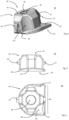
- figure 1 shows a lightweight fastener 10 from above in a 3D view.
- the two main components are the clip nut 40 installed in the cage 28, which forms the majority of the first leg 22 of the clip body 20.
- the first leg 22 is connected to the second leg 24 via a web 23 , which is functionally designed and referred to as a tongue 27 .
- the terms first leg 22, second leg 24 and connecting web 23 are primarily intended to be functional. Since the clip body 20 is constructed in one piece and these functional areas merge into one another, it is clear to the person skilled in the art that precise demarcation lines are neither useful nor necessary.
- figure 1 shows further details that can be provided in a series product from a structural point of view, such as recesses to save material, reinforcement ribs and gripping surfaces.
- FIG 2 12 is a top view of the clip body 20 of the lightweight fastener 10, ie the first leg 22.
- the structure of the cage 28 can be seen from above.
- the cage has a large opening 29 through the first leg 22 which allows parts of the second leg 24 and the tongue 27 to be viewed.
- the tongue 27 has a further opening 25 .
- the web 23 is shown in plan view.
- Two areas of the cage 28 have the openings 36 and 37 in the cage 28; they are indicated in dashed lines opposite one another in the longitudinal axis of the first leg 22. These openings are arranged parallel to the plane of extension of the first leg 22 .
- the figure 3 shows a side view of the clip body 20, again with the first leg 22, second leg 24 and connecting web 23.
- the cage 28 occupies the predominant part of the first leg 22. Between the cage 28 and the transition area to the web 23, the leg is equipped with a step that is oriented towards the inside of the clamp and provides an emergency contact surface 19.
- figure 1 shows the interaction of the emergency contact surface 19 and the stop edge 49 (cf. also figure 6 ).
- the opening 25 in the second leg 24 and the position of the opening 29 (first leg 22) are indicated by arrows.
- the opening 25 in the area of the tongue 27 is surrounded by a cut sleeve section 21, similar to a collar.
- FIG 4 shows a perspective view of a clip nut 40 as an isolated component. Its main components are the nut base 42 and the main body 44.
- the nut base 42 is shown as a substantially planar, plate-shaped base surface 43 with irregularly shaped edges.
- the planar base surface 43 (underside) transitions at one edge into the previously described chamfer 45.
- the main body 44 is shown as a basically polygonal body whose side walls 51, 51', 51",... are concave, interrupted by planar wall sections The side walls partially merge into slopes, which in turn open into the top surface 41.
- the central opening 46 is shown in the top surface with its internal thread 49.
- Two projections or lugs 56, 57 are attached to the main body, which serve as protection against loss (according to Mounting in the clip body. They come to lie in the openings 36, 37 in the mounted state.
- figure 5 shows a clip nut 40 in a schematic side view. It can be seen here that the nut base 42 has a flat base surface 43 ("underside"), while its upper side has a convex curvature.
- FIG. 14 is again a plan view of the clip nut from top surface 41.
- FIG. The irregular shape of the nut base 42 selected here can be seen. How to in synopsis of figure 1 and 6 recognizes, there are contact areas between the nut base and the receiving space 26 facing underside of the first leg 22 of the clip body 20. These support areas 47 and 48 are in figure 6 indicated by hatching. As also described above, because of the convexly curved surface of the nut base 42, the clip nut 40 can perform a rolling movement relative to the clip body.
- Feature 49 designates the stop edge, which (in the assembled state) can interact with the emergency contact surface 19 .
Landscapes
- Engineering & Computer Science (AREA)
- General Engineering & Computer Science (AREA)
- Mechanical Engineering (AREA)
- Connection Of Plates (AREA)
Description
Die vorliegende Erfindung befasst sich mit Leichtbaubefestigern, die in der Industrie als Clip oder nach dem englischen Begriff als clip nut bezeichnet werden. Grundsätzlich besteht ein solcher Clip aus einem aus einem klammerförmigen Klippkörper und einer daran beweglich gelagerten Klippmuttter. Die vorliegende Erfindung bezieht sich unter anderem auf einen Leichtbaubefestiger mit einer Klippmutter komplett aus Kunststoff.The present invention is concerned with lightweight fasteners, referred to in the industry as clips or clip nuts. Basically, such a clip consists of a clamp-like clip body and a clip nut movably mounted on it. The present invention relates, inter alia, to a lightweight fastener with a clip nut made entirely of plastic.
Im Fahrzeugbau wie in der Luftfahrtindustrie werden häufig Leichtbau-Verkleidungen eingesetzt, die lösbar befestigt werden müssen. Um spanende Verarbeitungsschritte bei der Endmontage zu vermeiden, werden solche z.B. plattenförmige Verkleidungselemente vorgebohrt und mit Clips versehen. In deren Verschraubungselemente greifen bei der Endmontage dann die Befestiger zu anderen Verkleidungselementen bzw. strukturell tragenden Elementen ein. Die plattenförmigen Elemente bzw. Bauteile sind hierbei häufig Leichtbauwandelemente bzw. Sandwichpanels, die aus Gewichtsgründen zumeist aus zwei Aussenlagen (aus Kunststoff oder Aluminium) bestehen, welche mit einer wabenförmigen Aussteifung dazwischen verklebt sind.In vehicle construction as well as in the aviation industry, lightweight panels are often used, which have to be detachably attached. In order to avoid machining steps during final assembly, such e.g. panel-shaped cladding elements are pre-drilled and provided with clips. During final assembly, the fasteners for other paneling elements or structurally supporting elements then engage in their screwing elements. The plate-shaped elements or components are often lightweight wall elements or sandwich panels, which for reasons of weight usually consist of two outer layers (made of plastic or aluminum) which are bonded with a honeycomb reinforcement in between.
Clips sind grundsätzlich aus dem Stand der Technik bekannt. Die
Die
Die
Allen drei Clip-Ausführungen ist gemein, dass Vorkehrungen getroffen wurden, um ein Mitdrehen der Mutter während des Eindrehens der Schraube zu verhindern. Die
Die vorliegende Erfindung hat zum Ziel, die oben genannten Nachteile des Standes der Technik zu verringern und insbesondere einen Clip vorzustellen, der verbesserte Eigenschaften in Bezug auf Montage, Handhabung und Herstellung aufweisen kann.The aim of the present invention is to reduce the above-mentioned disadvantages of the prior art and in particular to present a clip which can present improved assembly, handling and manufacturing characteristics.
Diese Aufgabe wird durch eine im Grundsatz zweiteiligen Leichtbaubefestiger aus Klippkörper und Klippmutter gelöst mit den Merkmalen des unabhängigen Anspruchs 1. Die Unteransprüche beschreiben weitere Varianten und Ausführungsbeispiele.This object is achieved by a basically two-part lightweight fastener made of clip body and clip nut with the features of independent claim 1. The dependent claims describe further variants and exemplary embodiments.
Ein erfindungsgemässer Leichtbaubefestiger umfasst einen einstückigen Klippkörper aus Kunststoff und eine Klippmutter. Wie im Stand der Technik weist der Klippkörper die Grundform einer Klemme auf, mit zwei sich gegenüberliegenden, sich in Längsrichtung erstreckenden Schenkeln und einem, zwei gegenüberliegende Schenkel-Enden verbindenden Steg. Die beiden zugewandten Flächen der Schenkel und der Steg beschreiben bzw. begrenzen somit einen Aufnahmeraum für ein plattenförmiges Bauteil.A lightweight fastener according to the invention comprises a one-piece plastic clip body and a clip nut. As in the prior art, the clip body has the basic shape of a clamp, with two opposite legs extending in the longitudinal direction and a web connecting two opposite leg ends. The two facing surfaces of the legs and the web thus describe or delimit a receiving space for a plate-shaped component.
Der Begriff Aufnahmeraum soll dabei als das Volumen verstanden werden, der von den Grenzflächen der beiden Schenkel und dem Steg beschrieben wird. Der Begriff "Innenseite" bzw. "Innenbereich" beim Klippkörper bzw. Leichtbaubefestiger bezieht sich ebenfalls auf diesen Innenbereich zwischen den beiden Schenkeln des Klippkörpers. Die Begriffe "oben" und "unten" beziehen sich auf die übliche Darstellung eines Clips ähnlich der Darstellung in
Die Klippmutter wiederum weist eine Mutternbasis auf, die im Wesentlichen plattenförmig ausgestaltet ist mit einer flachen, zur Klemmeninnenseite weisenden, ebenen Basisfläche. Auf der Mutternbasis (genauer: auf der der Basisfläche entgegengesetzten (Ober-)Seite) baut ein Hauptkörper auf mit einer Deckfläche sowie eine Mehrzahl an Seitenwänden, die sich zwischen Mutternbasis und Deckfläche erstrecken.The clip nut, in turn, has a nut base that is essentially plate-shaped with a flat, planar base surface pointing toward the inside of the clamp. A main body is built on the nut base (more precisely: on the (top) side opposite the base surface) with a cover surface and a plurality of side walls which extend between the nut base and the cover surface.
Somit ähnelt, vereinfacht gesagt, die Mutternbasis einem unregelmässig ausgestalteten Flansch, der den Hauptkörper an seinem unteren Ende abschliesst.Thus, to put it simply, the nut base resembles an irregularly shaped flange which closes off the main body at its lower end.
Der Hauptkörper hat einen im Wesentlichen polygonen Querschnitt parallel zur Mutternbasis. In üblicher Betrachtungsweise weist also der Horizontalquerschnitt eine irreguläre Form auf, bevorzugt als Vieleck. Seiner Funktion als Klippmutter folgend, hat der Hauptkörper eine zentrale Mittenöffnung, die sich durch die Mutternbasis, den Hauptkörper und die Deckfläche erstreckt (vertikale Durchgangsöffnung).The main body has a generally polygonal cross section parallel to the nut base. In the usual way of looking at it, the horizontal cross section has an irregular shape, preferably as a polygon. Following its function as a clip nut, the main body has a central central opening that extends through the nut base, main body and top surface (vertical through hole).
Der erste Schenkel des Klippkörpers trägt einen Käfig aus mehreren Wandelementen, in dem die Klippmutter schwimmend beweglich gelagert ist. Mit Käfig ist die bei Clips übliche Aufnahme bzw. bewegliche Lagerung der Klippmutter gemeint. Der Käfig hält die Klippmutter mit Spiel. Dieser Käfig weist hierzu mindestens zwei Halteöffnungen auf.The first leg of the clip body carries a cage made up of several wall elements, in which the clip nut is mounted so that it can move in a floating manner. The term “cage” refers to the mounting or movable mounting of the clip nut that is usual with clips. The cage holds the clip nut with play. For this purpose, this cage has at least two holding openings.
Der zweite Schenkel des Klippkörpers ist zur Klemmen-Innenseite als zungenförmige, flache Anlagefläche ausgestaltet. Mit Anlagefläche ist damit die Kontaktfläche mit einem Bauteil gemeint, auf das der Leichtbaubefestiger aufgeschoben wird.The second leg of the clip body is designed as a tongue-shaped, flat contact surface on the inside of the clamp. The contact surface means the contact surface with a component onto which the lightweight fastener is pushed.
Beide Schenkel, und zwar der erste Schenkel im Bereich des Käfigs und der zweite Schenkel im Bereich der Zunge, weisen jeweils eine Öffnung auf, die mit der zentralen Mittenöffnung der im Käfig angeordneten Klippmutter fluchten.Both legs, namely the first leg in the area of the cage and the second leg in the area of the tongue, each have an opening which is aligned with the central opening of the clip nut arranged in the cage.
Weiterhin ist der erste Schenkel so ausgestaltet, dass die Basisfläche der Klippmutter zur Innenseite der Klemme weist und als Anlagefläche ausgebildet ist für den direkten Kontakt mit dem plattenförmigen Bauteil. In den meisten Ausführungen des Standes der Technik wird die Klippmutter als Bauteil auf der Oberseite eines Schenkels gehaltert und presst damit, im verbauten Zustand, auf den Schenkel. Dieser wirkt also als Unterlagscheibe für die Klippmutter. Bei der vorliegenden Erfindung ist der erste Schenkel so ausgeführt, dass die Mutternbasis Teil der Innenseite des ersten Schenkels bildet. Idealerweise wird die restliche Innenfläche des Schenkels so ausgeführt, dass sie flächig mit der Basisfläche der Mutternbasis fluchtet. Sie kann alternativ auch geringfügig flächig versetzt sein, damit in jedem Anwendungsfall die Basisfläche der Mutternbasis am Bauteil anliegen kann.Furthermore, the first leg is designed in such a way that the base surface of the clip nut faces the inside of the clamp and is designed as a contact surface for direct contact with the plate-shaped component. In most designs of the prior art, the clip nut is held as a component on the upper side of a leg and thus, when installed, presses on the leg. This acts as a washer for the clip nut. In the present invention, the first leg is configured such that the nut base forms part of the inside of the first leg. Ideally, the remaining inner surface of the leg is designed so that it is flush with the base surface of the nut base. Alternatively, it can also be offset slightly across the surface, so that the base surface of the nut base can rest against the component in every application.
Ferner weist der Hauptkörper der Klippmutter mindestens zwei zapfenförmige Nasen auf, die in die entsprechenden Öffnungen der Wandelemente des Käfigs eingreifen. Bevorzugt werden diese Nasen an gegenüberliegenden Seiten des Hauptkörpers angeordnet und sind so dimensioniert, dass sie in den zugehörigen Öffnungen Spiel haben. Die Nasen haben im Zusammenspiel mit den Öffnungen des Käfigs die Hauptfunktion einer Verliersicherung und weniger die einer Drehmomentstütze. Diese Kraftübertragung bzw. Drehmomentübertragung beim Eindrehen eines Befestigers in die zentrale Mittenöffnung erfolgt vorrangig durch die Seitenwände des Hauptkörpers auf die Wandelemente des Käfigs.Furthermore, the main body of the clip nut has at least two peg-shaped lugs which engage in the corresponding openings in the wall elements of the cage. Preferably, these lugs are located on opposite sides of the main body and are dimensioned to have clearance in the associated openings. In interaction with the openings of the cage, the lugs have the main function of securing against loss and less of a torque arm. This power transmission or torque transmission when screwing a fastener into the central opening takes place primarily through the side walls of the main body to the wall elements of the cage.
Bevorzugt ist eine Anzahl von n Seitenwänden des Klippmutter-Hauptkörpers konkav gewölbt, wobei gilt n=>3. Da die Form des Horizontalquerschnitts des Hauptkörpers als Polygon beschrieben wurde, könnte also ein Sechseck mit z.B. 3 oder 4 konkav (nach innen) gewölbten Seiten diese Bedingung erfüllen. Ebenso ein Oktagon mit z.B. 4 oder 6 konkaven Seiten. Ausdrücklich kann vorgesehen sein, dass zwischen konkaven (Seiten-)Wandflächen auch weitere gerade oder konvexe Seitenwände vorgesehen sein können. Diese Wandflächen können stetig ineinander übergehen oder durch Kanten getrennt sein. Entscheidend ist das Zusammenspiel mit den Wandelementen des Käfigs.A number of n side walls of the main body of the clip nut are preferably curved in a concave manner, where n=>3. Since the shape of the horizontal cross-section of the main body has been described as a polygon, a hexagon with, for example, 3 or 4 concave (inwardly) curved sides could fulfill this condition. Also an octagon with e.g. 4 or 6 concave sides. Provision can expressly be made for further straight or convex side walls to be provided between concave (side) wall surfaces. These wall surfaces can merge into one another continuously or be separated by edges. The decisive factor is the interaction with the wall elements of the cage.
Ein Leichtbaubefestiger gemäss Erfindung kann daher mindestens n nach innen gerichtete Wandelemente des Käfigs aufweisen, die konvex nach innen gewölbt sind. "Nach innen" ist dabei als "dem von den Wandelementen umschriebenen Bereich zugewandt" zu verstehen. In bevorzugter Ausführung stehen die Seitenwände des Klippmutter-Hauptkörpers und die Wandelemente des Käfigs sich paarweise gegenüber. In weiter bevorzugten Ausführungsformen wird die Wölbung der Seitenwände bzw. Wandelemente der Form von Kegelschnitten folgen, also im Horizontalquerschnitt (parallel zur Basisfläche) als kreisabschnittsförmig, elliptisch, parabolisch oder hyperbolisch beschreibbar sind. Konstruktiv bevorzugt wird hierbei die Wölbung als Kreisbogen ausgeführt. In einer konstruktiv und herstelltechnisch bevorzugten Ausführung werden somit die Wölbungen dieselbe geometrische Grundform nutzen. Noch weiter bevorzugt können die Radien der Kreisbögen für die konkaven Seitenwände bzw. konvexen Wandelemente im Wesentlichen gleich gross gewählt werden.A lightweight fastener according to the invention can therefore have at least n inwardly directed wall elements of the cage, which are convexly curved inwards. "Inwards" is to be understood as "facing the area circumscribed by the wall elements". In a preferred embodiment, the side walls of the clip nut main body and the wall elements of the cage face each other in pairs. In further preferred embodiments, the curvature of the side walls or wall elements follows the shape of conic sections, ie can be described as a circular section, elliptical, parabolic or hyperbolic in horizontal cross section (parallel to the base surface). In this case, the curvature is preferably designed as a circular arc. In an embodiment that is preferred in terms of design and production technology, the bulges will thus use the same basic geometric shape. Even more preferably, the radii of the circular arcs for the concave side walls or convex wall elements can be chosen to be essentially the same size.
Betrachtet man die vorbeschriebenen Merkmale zusammen, so ist die Aussenform der Klippmutter-Seitenwände komplementär zu den Wandelementen des Käfigs, Aussenwölbung trifft auf Innenwölbung. Wird also ein Befestiger mit der Klippmutter verbunden, wird anfänglich sicher die Klippmutter vom Befestiger bis zu einem gewissen Grad mitgedreht, bis die Drehbewegung gehindert wird. Die schwimmende Lagerung der Klippmutter im Käfig stellt ja diesen Freiheitsgrad geplant zur Verfügung. Im Stand der Technik mit Nasen und Vorsprüngen als Drehmomentstützen dienen diese der Kraftableitung. Bei der vorliegenden Erfindung wird dies durch den Kontakt der Seitenwände / Wandelemente erreicht. Dabei wird sich der Kontakt je nach Ausrichtung bzw. Orientierung von Befestiger, Klippmutter und Käfig selbstständig einstellen. Die Kontaktfläche könnte demnach über eine oder mehrere Flächen gleichzeitig erfolgen. Durch die wesentlich grösseren Kontakt-Flächen im Vergleich zu den Stegen oder Nasen im Stand der Technik wird eine schonendere Kraftableitung erreicht, was ein optimiertes Design des gesamten Leichtbaubefestigers erlaubt.Considering the features described above together, the outer shape of the clip nut side walls is complementary to the wall elements of the cage, outer curve meets inner curve. So when a fastener is connected to the clip nut, initial sure the clip nut is rotated by the fastener to some extent until rotation is prevented. The floating mounting of the clip nut in the cage provides this degree of freedom as planned. In the prior art with lugs and projections as torque supports, these serve to dissipate force. In the present invention, this is accomplished through the contact of the sidewalls/panels. Depending on the alignment or orientation of the fastener, clip nut and cage, the contact will adjust itself automatically. The contact area could therefore take place over one or more areas at the same time. Due to the significantly larger contact surfaces compared to the webs or lugs in the prior art, a gentler force dissipation is achieved, which allows an optimized design of the entire lightweight fastener.
Die zentrale Mittenöffnung der Klippmutter wird in bevorzugter Ausführung mit einem Innengewinde ausgestattet. Alternativ und äquivalent zu einem Schraubgewinde können auch andere Befestigungsarten vorgesehen werden, z.B. Bajonettverschlüsse, Schnapphalterungen, Dreh-Klemmverschlüsse.In a preferred embodiment, the central opening of the clip nut is equipped with an internal thread. As an alternative and equivalent to a screw thread, other types of attachment can also be provided, e.g. bayonet locks, snap-on mounts, rotary clamp locks.
Es hat sich gezeigt, dass die Klippmutter einteilig aus Kunststoff, bevorzugt einem Thermoplast, insbesondere PEEK, gefertigt werden kann. Zuschläge wie Glasfasern, Kohlefasern oder andere vor allem spritzgiessfähige Zuschlagstoffe können verwendet werden, um die Festigkeit der Klippmutter wie gewünscht bzw. gefordert, einzustellen.It has been shown that the clip nut can be made in one piece from plastic, preferably a thermoplastic, in particular PEEK. Additives such as glass fibers, carbon fibers or other injection-mouldable additives can be used in order to adjust the strength of the clip nut as desired or required.
In einer besonderen Ausführungsform kann der der Deckfläche zugewandte Auslauf des Gewindes so ausgelegt werden, dass ein eingeschraubter Befestiger klemmend gesichert wird. Dabei kann auf die im Stand der Technik bekannten Methoden zurückgegriffen werden, indem beispielsweise die Gewindegrate leicht verbreitert werden, die Gewindesteigung verändert wird oder das Gewinde nicht vollständig ausgeformt wird. Alternativ oder ergänzend wäre auch denkbar, den Gewindeauslauf mit aufgetragenen Beschichtungen, Klebern oder anderen Materiallagen zu versehen, um den Widerstand im Gewinde-Endbereich zu erhöhen und die Schraubverbindung somit zu sichern. Es hat sich gezeigt, dass die Ausführung des Gewindes in Kunststoff bei Wahl der entsprechenden Festigkeit problemlos möglich ist.In a particular embodiment, the end of the thread facing the top surface can be designed in such a way that a screwed-in fastener is secured in a clamping manner. The methods known in the prior art can be used here, for example by slightly widening the thread ridges, changing the thread pitch or not fully forming the thread. Alternatively or additionally, it would also be conceivable to apply coatings, adhesives or other layers of material to the end of the thread in order to increase the resistance in the end area of the thread and thus secure the screw connection. It has been shown that the execution of the thread in plastic is possible without any problems if the corresponding strength is selected.
In einer weiteren Ausführungsform kann die Mutternbasis so ausgelegt werden, dass sie auf ihrer der Basisfläche abgewandte Oberseite Auflagebereiche aufweist, die eine konkave Wölbung haben und so ausgerichtet sind, dass sie eine Abrollbewegung bzw. Verkippung der Klippmutter entlang des ersten Schenkels erlauben. Wie bereits erwähnt, dienen die Nasen am Hauptkörper, die in den zugehörigen Öffnungen des Käfigs gelagert sind, vorrangig der Verliersicherung. Die gewölbte Oberseite der Mutternbasis bzw. die Auflageflächen dieser Oberseite sind durch die Flansch-ähnliche Auskragung des Hauptkörpers der Unterseite des Käfigs bzw. des ersten Schenkels zugewandt. Wie oben erwähnt, bildet die Basisfläche ja eine direkte Auflagefläche für das zu sichernde Bauteil, daher liegt konsequenterweise der Käfig auf der gewölbte Oberseite der Mutternbasis bzw. den Auflageflächen dieser Oberseite auf. Durch die gewählte Form (halbrunde Wölbung) entsteht eine zusätzliche Kippbeweglichkeit zwischen dem ersten Schenkel / Käfigunterseite und der Klippmutter.In a further embodiment, the nut base can be designed such that it has contact areas on its top side facing away from the base area, which have a concave curvature and are aligned in such a way that they allow the clip nut to roll or tilt along the first leg. As already mentioned, the lugs on the main body, which are stored in the corresponding openings of the cage, serve primarily the loss protection. The domed top of the nut base or the bearing surfaces of this top face through the flange-like projection of the main body to the bottom of the cage or the first leg. As mentioned above, the base surface forms a direct contact surface for the component to be secured, so the cage consequently lies on the curved upper side of the nut base or the contact surfaces of this upper side. The selected shape (semicircular curvature) creates additional tilting mobility between the first leg / cage bottom and the clip nut.
Ferner kann an der Mutternbasis eine zur Basisfläche angeschrägte Fase vorgesehen werden. Diese wird bevorzugt auf der dem Steg abgewandten Seite der Klippmutter angebracht und unterstützt bzw. erleichtert das Aufschieben des Leichtbaubefestigers auf das Bauteil.Furthermore, a chamfer which is bevelled towards the base surface can be provided on the nut base. This is preferably attached to the side of the clip nut facing away from the web and supports or facilitates the sliding of the lightweight fastener onto the component.
Weiterhin kann vorgesehen werden, dass die Mutternbasis an der, der Fase entgegengesetzten Kante eine Anschlagkante aufweist. Wenn die Klippmutter im Käfig gelagert ist (mit anderen Worten: korrekt verbaut) entsteht so eine Notanlagefläche parallel beabstandet zur einer Gegenfläche am Klippkörper gegenüber.Furthermore, it can be provided that the nut base has a stop edge on the edge opposite the bevel. When the clip nut is mounted in the cage (in other words: installed correctly), an emergency contact surface is created, spaced parallel to a mating surface on the opposite clip body.
Analog zur Klippmutter kann der Klippkörper einstückig aus Kunststoff, bevorzugt einem Thermoplast, insbesondere PEEK, gefertigt werden. Seiner Bestimmung als Klammer folgend kann der Klippkörper bevorzugt als 2-Komponenten-Spritzguss einstückig ausgeführt werden, wobei die erste Kunststoffkomponente elastischer gewählt wird als die zweite. Die Einstellung der Festigkeit bzw. Elastizität der Kunststoffkomponenten kann in bekannter Weise durch Zuschlagstoffe wie Glas- oder Kohlefasern realisiert werden.Analogously to the clip nut, the clip body can be made in one piece from plastic, preferably a thermoplastic, in particular PEEK. Following its determination as a clip, the clip body can preferably be designed as a 2-component injection molding in one piece, with the first plastic component being chosen to be more elastic than the second. The strength or elasticity of the plastic components can be adjusted in a known manner using additives such as glass or carbon fibers.
Bevorzugt wird die elastischere Komponente überwiegend im Bereich der zweiten Schenkels bzw. der Zunge und im Bereich des Steges zum Einsatz kommen. Damit lässt sich das Aufschieben auf das Bauteil einfacher realisieren, weil Zunge und Steg elastisch nachgebend den Montageprozess unterstützen. Dagegen kann der Käfig beispielsweise in einer Ausführung mit glasgefülltem PEEK eine rigidere Struktur erhalten.The more elastic component is preferably used predominantly in the area of the second leg or the tongue and in the area of the web. This makes it easier to slide onto the component, because the elastically yielding tongue and web support the assembly process. In contrast, the cage can have a more rigid structure, for example in an embodiment with glass-filled PEEK.
Die Erfindung wird nun mit Bezug auf die begleitenden Zeichnungen anhand besonders bevorzugter Ausführungsformen beispielhaft erläutert.
-
Figur 1 zeigt eine perspektivische Sicht auf einen erfindungsgemäßen Leichtbaubefestiger. -
Figur 2 zeigt einen Klippkörper ohne Klippmutter schematisch von oben. -
Figur 3 zeigt einen Klippkörper ohne Klippmutter schematisch von der Seite. -
Figur 4 zeigt eine perspektivische Sicht auf eine Klippmutter -
Figur 5 zeigt eine Seitenansicht einer Klippmutter -
Figur 6 zeigt die Ansicht einer Klippmutter von oben.
-
figure 1 shows a perspective view of a lightweight fastener according to the invention. -
figure 2 shows a clip body without clip nut schematically from above. -
figure 3 shows a clip body without a clip nut schematically from the side. -
figure 4 shows a perspective view of a clip nut -
figure 5 shows a side view of a clip nut -
figure 6 shows a view of a clip nut from above.
In
Die
Dieser dient dazu, den Leichtbaubefestiger auf der Öffnung in dem (hier nicht gezeigten) Bauteil zu zentrieren. Die Abschrägung zur Einführöffnung in den Aufnahmeraum 26 erleichtert das Aufschieben des Leichtbaubefestigers auf das Bauteil.This serves to center the lightweight fastener on the opening in the component (not shown here). The bevel towards the insertion opening into the receiving
Die in den
Claims (16)
- Lightweight fastener (10) having an integral clip body (20) made of plastic,- wherein the clip body (20) has the basic shape of a clamp- having two opposite, longitudinally extending legs (22, 24)- and a web (23) connecting two opposite leg ends;- having a receiving space (26) for a plate-shaped component between the legs (22, 24), which is bounded on one side by the web (23);and a clip nut (40)- which has a nut base (42) that is substantially plate-shaped with a flat base surface (43) facing the inside of the clamp;- and a main body (44) supported on the nut base (42) and a top surface (41) and a plurality of side walls (51, 51', 52",...) extending between the nut base (42) and the top surface (41);- wherein the main body (44) has a substantially polygonal cross-section parallel to the nut base (42);- and a central center opening (46) extending through the nut base (42), the main body (44) and the top surface (41);wherein- a first leg (22) of the clip body (20) comprises a cage (28) of a plurality of wall elements (31, 31', 31", ...) in which the clip nut (40) is floatingly movably mounted;- the cage (28) has at least two retaining openings (36, 37)- the second leg (24) is designed as a tongue-shaped, flat contact surface (27) towards the inside of the clamp- the first leg in the region of the cage (28), the second leg in the region of the tongue-shaped, flat contact surface (27) each have an opening (29, 25) which is aligned with the central center opening (46) of the clip nut (40) arranged in the cage (28),characterized in that- the first leg (22) is designed such that the base surface (43) of the clip nut (40) faces the inside of the clamp and is designed as a contact surface for direct contact with the plate-shaped component;- the main body (44) of the clip nut (40) has at least two peg-shaped lugs (56, 57) which engage in the openings (36, 37) of the wall elements of the cage (28).
- Lightweight fastener according to claim 1, characterized in that a number of n side walls (51, 51', 51",...) of the clip nut main body (44) are concavely curved, wherein n=>3 applies.
- Lightweight fastener according to claim 1-2, characterized in that at least n inwardly directed wall elements (31, 31', 31",...) of the cage (28) are convexly inwardly curved.
- Lightweight fastener according to claim 1-3, characterized in that the side walls (51, 51', 51",...) of the clip nut main body (44) and the wall elements (31, 31', 31",...) of the cage (28) face each other in pairs.
- Lightweight fastener according to claim 2-4, characterized in that the curvature of the side walls (51, 51', 51",...) or wall elements (31, 31', 31",...) follow the shape of conical sections, i.e. can be described in horizontal cross-section as circular sectional, elliptical, parabolic or hyperbolic.
- Lightweight fastener according to claim 2-5, characterized in that the curvature of the side walls (51, 51', 51",...) or wall elements (31, 31', 31",...) is designed as circular arcs.
- Lightweight fastener according to claim 6, characterized in that the radii of the circular arcs for the concave side walls (51, 51', 51",...) or convex wall elements (31, 31', 31",...) are selected to be substantially equal in size.
- Lightweight fastener according to claim 1-7, characterized in that the central center opening (46) of the clip nut (40) has an internal thread (49).
- Lightweight fastener according to claim 1-8, characterized in that the clip nut (20) is integrally made from plastic, preferably a thermoplastic, in particular PEEK.
- Lightweight fastener according to claim 8-9, characterized in that the outlet of the thread (49) facing the top surface (41) is designed to clamp a screwed-in fastener.
- Lightweight fastener according to claim 1-10, characterized in that the nut base (42) includes, on its upper surface opposite the base surface (43), support portions (47, 48) having a concave curvature and oriented to permit rolling movement or tilting of the clip nut (40) along the first leg (22).
- Lightweight fastener according to claim 1-11, characterized in that the nut base (42) has a chamfer (45) that is beveled toward the base surface.
- Lightweight fastener according to claim 12, characterized in that the nut base (42) has, on the edge opposite the chamfer (45), a stop edge (49) which, when the clip nut (40) is mounted in the cage (48), is arranged opposite an emergency contact surface (19) at a parallel distance.
- Lightweight fastener according to claim 1-13, characterized in that the clip body is integrally made from plastic, preferably a thermoplastic, in particular PEEK.
- Lightweight fastener according to claim 1-14, characterized in that the clip body is integrally made as a 2-component injection molding, wherein the first plastic component is selected to be more elastic than the second.
- Lightweight fastener according to claim 15, characterized in that the more elastic component is used predominantly in the region of the second leg (22) or the tongue (27) and in the region of the web (23).
Priority Applications (4)
| Application Number | Priority Date | Filing Date | Title |
|---|---|---|---|
| EP20152361.0A EP3851686B1 (en) | 2020-01-17 | 2020-01-17 | Lightweight fastener |
| PCT/EP2021/050790 WO2021144411A1 (en) | 2020-01-17 | 2021-01-15 | Lightweight-construction fastener |
| CN202180007499.7A CN115003923A (en) | 2020-01-17 | 2021-01-15 | Light structure fastener |
| US17/793,078 US12000423B2 (en) | 2020-01-17 | 2021-01-15 | Lightweight-construction fastener |
Applications Claiming Priority (1)
| Application Number | Priority Date | Filing Date | Title |
|---|---|---|---|
| EP20152361.0A EP3851686B1 (en) | 2020-01-17 | 2020-01-17 | Lightweight fastener |
Publications (2)
| Publication Number | Publication Date |
|---|---|
| EP3851686A1 EP3851686A1 (en) | 2021-07-21 |
| EP3851686B1 true EP3851686B1 (en) | 2023-03-29 |
Family
ID=69177037
Family Applications (1)
| Application Number | Title | Priority Date | Filing Date |
|---|---|---|---|
| EP20152361.0A Active EP3851686B1 (en) | 2020-01-17 | 2020-01-17 | Lightweight fastener |
Country Status (4)
| Country | Link |
|---|---|
| US (1) | US12000423B2 (en) |
| EP (1) | EP3851686B1 (en) |
| CN (1) | CN115003923A (en) |
| WO (1) | WO2021144411A1 (en) |
Families Citing this family (3)
| Publication number | Priority date | Publication date | Assignee | Title |
|---|---|---|---|---|
| USD1039369S1 (en) * | 2022-07-28 | 2024-08-20 | Seakeeper, Inc. | Nut retainer |
| USD1039959S1 (en) * | 2022-07-28 | 2024-08-27 | Seakeeper, Inc. | Nut retainer |
| CN116557391B (en) * | 2023-07-10 | 2023-09-12 | 浙江易锻精密机械有限公司 | Buckle and stamping equipment |
Family Cites Families (14)
| Publication number | Priority date | Publication date | Assignee | Title |
|---|---|---|---|---|
| FR2649454B1 (en) | 1989-07-06 | 1991-11-15 | Rapid Sa | NUT, FORCEPS, MOUNTED ON THE EDGE OF A PANEL OR THE LIKE |
| US5423646A (en) | 1993-02-24 | 1995-06-13 | Buell Industries, Inc. | U-nut |
| US6474917B2 (en) * | 2000-06-22 | 2002-11-05 | Jacques Gauron | Clip nuts |
| US6854941B2 (en) * | 2003-04-09 | 2005-02-15 | The Monadnock Company, Inc. | Clip nut |
| WO2006024527A1 (en) * | 2004-09-02 | 2006-03-09 | Ejot Gmbh & Co. Kg | U-shaped clamp |
| DE102005045723B3 (en) * | 2005-09-23 | 2007-05-03 | A. Raymond Et Cie | Crab |
| US8177466B2 (en) | 2007-06-13 | 2012-05-15 | The Monadnock Company | Apparatus and methods for fastening a panel or other components |
| US7959392B2 (en) * | 2008-05-16 | 2011-06-14 | Illinois Tool Works Inc. | U-nut fastener assembly |
| FR2934336B1 (en) * | 2008-07-22 | 2010-09-17 | Lisi Automotive Rapid | NUT CLAMP DEVICE MOUNTING ON THE EDGE OF A PANEL OR THE LIKE |
| US7648319B1 (en) * | 2008-11-12 | 2010-01-19 | Orlando Ochoa | Clip nut fastener |
| DE102016111933A1 (en) * | 2016-06-29 | 2018-01-04 | Sfs Intec Holding Ag | Lightweight construction fastener with wire thread nut |
| DE102016118657A1 (en) * | 2016-09-30 | 2018-04-05 | Sfs Intec Holding Ag | 2-COMPONENT CLIP |
| DE102016118676A1 (en) * | 2016-09-30 | 2018-04-05 | Sfs Intec Holding Ag | Leichtbaubefestiger |
| US11415164B2 (en) * | 2018-10-23 | 2022-08-16 | AlphaUSA | Retainer and a retainer and nut assembly |
-
2020
- 2020-01-17 EP EP20152361.0A patent/EP3851686B1/en active Active
-
2021
- 2021-01-15 WO PCT/EP2021/050790 patent/WO2021144411A1/en active Application Filing
- 2021-01-15 CN CN202180007499.7A patent/CN115003923A/en active Pending
- 2021-01-15 US US17/793,078 patent/US12000423B2/en active Active
Also Published As
| Publication number | Publication date |
|---|---|
| US20230040255A1 (en) | 2023-02-09 |
| EP3851686A1 (en) | 2021-07-21 |
| US12000423B2 (en) | 2024-06-04 |
| WO2021144411A1 (en) | 2021-07-22 |
| CN115003923A (en) | 2022-09-02 |
Similar Documents
| Publication | Publication Date | Title |
|---|---|---|
| EP3851686B1 (en) | Lightweight fastener | |
| DE3535210C2 (en) | ||
| EP2003346B1 (en) | Fixing device with tolerance compensation | |
| WO2012048686A1 (en) | Cage nut | |
| DE29519375U1 (en) | Plastic fastening element, in particular for a vehicle trim | |
| EP0697267A1 (en) | Mounting device for a tool or a workpiece | |
| EP1780424A1 (en) | Fastening arrangement with tolerance compensation | |
| EP1626185A1 (en) | Adjusting unit for adjusting the distance between two construction units | |
| EP3526476B1 (en) | Floatingly mounted clip | |
| WO2017032545A1 (en) | Two-part plug-in coupling for connecting components | |
| EP0232917B1 (en) | Method as well as clamp and support for the mounting of visual display devices | |
| EP4095396A1 (en) | Tolerance compensating device | |
| DE202005019612U1 (en) | Device for releasably securing a flat component to a support structure | |
| EP1862356B1 (en) | Retaining clip | |
| EP1612432B1 (en) | Fastening assembly for a trim panel and fastening method | |
| DE20015831U1 (en) | Telescopic linear drive | |
| EP2304250B1 (en) | Screw clip | |
| DE102022134745A1 (en) | FIXING ARRANGEMENT WITH TOLERANCE COMPENSATION | |
| DE3114283A1 (en) | Plastic fastening element, in particular for the releasable fastening of flat workpieces | |
| EP1777791A2 (en) | End piece and / or connecting piece | |
| DE102012112362B3 (en) | Valve with a fastening device | |
| WO2006034867A1 (en) | Rivet ot screw connection of a plastic part to another part | |
| EP1394420A2 (en) | Insert for a wall opening, particularly in a vehicle body | |
| DE102011050287A1 (en) | Clamping screw for use in screw connection for wedge-fixing of e.g. solar cell module at roof, has screw head comprising closure unit for implementing frame surface during fixing screw for creating connection between frame and screw | |
| DE3842850C2 (en) | Connecting element for producing a releasable connection between at least two parts of a motor vehicle |
Legal Events
| Date | Code | Title | Description |
|---|---|---|---|
| PUAI | Public reference made under article 153(3) epc to a published international application that has entered the european phase |
Free format text: ORIGINAL CODE: 0009012 |
|
| STAA | Information on the status of an ep patent application or granted ep patent |
Free format text: STATUS: THE APPLICATION HAS BEEN PUBLISHED |
|
| AK | Designated contracting states |
Kind code of ref document: A1 Designated state(s): AL AT BE BG CH CY CZ DE DK EE ES FI FR GB GR HR HU IE IS IT LI LT LU LV MC MK MT NL NO PL PT RO RS SE SI SK SM TR |
|
| STAA | Information on the status of an ep patent application or granted ep patent |
Free format text: STATUS: REQUEST FOR EXAMINATION WAS MADE |
|
| 17P | Request for examination filed |
Effective date: 20220121 |
|
| RBV | Designated contracting states (corrected) |
Designated state(s): AL AT BE BG CH CY CZ DE DK EE ES FI FR GB GR HR HU IE IS IT LI LT LU LV MC MK MT NL NO PL PT RO RS SE SI SK SM TR |
|
| RAP3 | Party data changed (applicant data changed or rights of an application transferred) |
Owner name: SFS GROUP INTERNATIONAL AG |
|
| GRAP | Despatch of communication of intention to grant a patent |
Free format text: ORIGINAL CODE: EPIDOSNIGR1 |
|
| STAA | Information on the status of an ep patent application or granted ep patent |
Free format text: STATUS: GRANT OF PATENT IS INTENDED |
|
| INTG | Intention to grant announced |
Effective date: 20230119 |
|
| GRAS | Grant fee paid |
Free format text: ORIGINAL CODE: EPIDOSNIGR3 |
|
| GRAA | (expected) grant |
Free format text: ORIGINAL CODE: 0009210 |
|
| STAA | Information on the status of an ep patent application or granted ep patent |
Free format text: STATUS: THE PATENT HAS BEEN GRANTED |
|
| AK | Designated contracting states |
Kind code of ref document: B1 Designated state(s): AL AT BE BG CH CY CZ DE DK EE ES FI FR GB GR HR HU IE IS IT LI LT LU LV MC MK MT NL NO PL PT RO RS SE SI SK SM TR |
|
| REG | Reference to a national code |
Ref country code: CH Ref legal event code: EP |
|
| REG | Reference to a national code |
Ref country code: DE Ref legal event code: R096 Ref document number: 502020002828 Country of ref document: DE |
|
| REG | Reference to a national code |
Ref country code: AT Ref legal event code: REF Ref document number: 1556857 Country of ref document: AT Kind code of ref document: T Effective date: 20230415 |
|
| REG | Reference to a national code |
Ref country code: IE Ref legal event code: FG4D Free format text: LANGUAGE OF EP DOCUMENT: GERMAN |
|
| REG | Reference to a national code |
Ref country code: LT Ref legal event code: MG9D |
|
| PG25 | Lapsed in a contracting state [announced via postgrant information from national office to epo] |
Ref country code: RS Free format text: LAPSE BECAUSE OF FAILURE TO SUBMIT A TRANSLATION OF THE DESCRIPTION OR TO PAY THE FEE WITHIN THE PRESCRIBED TIME-LIMIT Effective date: 20230329 Ref country code: NO Free format text: LAPSE BECAUSE OF FAILURE TO SUBMIT A TRANSLATION OF THE DESCRIPTION OR TO PAY THE FEE WITHIN THE PRESCRIBED TIME-LIMIT Effective date: 20230629 Ref country code: LV Free format text: LAPSE BECAUSE OF FAILURE TO SUBMIT A TRANSLATION OF THE DESCRIPTION OR TO PAY THE FEE WITHIN THE PRESCRIBED TIME-LIMIT Effective date: 20230329 Ref country code: LT Free format text: LAPSE BECAUSE OF FAILURE TO SUBMIT A TRANSLATION OF THE DESCRIPTION OR TO PAY THE FEE WITHIN THE PRESCRIBED TIME-LIMIT Effective date: 20230329 Ref country code: HR Free format text: LAPSE BECAUSE OF FAILURE TO SUBMIT A TRANSLATION OF THE DESCRIPTION OR TO PAY THE FEE WITHIN THE PRESCRIBED TIME-LIMIT Effective date: 20230329 |
|
| P01 | Opt-out of the competence of the unified patent court (upc) registered |
Effective date: 20230622 |
|
| REG | Reference to a national code |
Ref country code: NL Ref legal event code: MP Effective date: 20230329 |
|
| PG25 | Lapsed in a contracting state [announced via postgrant information from national office to epo] |
Ref country code: SE Free format text: LAPSE BECAUSE OF FAILURE TO SUBMIT A TRANSLATION OF THE DESCRIPTION OR TO PAY THE FEE WITHIN THE PRESCRIBED TIME-LIMIT Effective date: 20230329 Ref country code: NL Free format text: LAPSE BECAUSE OF FAILURE TO SUBMIT A TRANSLATION OF THE DESCRIPTION OR TO PAY THE FEE WITHIN THE PRESCRIBED TIME-LIMIT Effective date: 20230329 Ref country code: GR Free format text: LAPSE BECAUSE OF FAILURE TO SUBMIT A TRANSLATION OF THE DESCRIPTION OR TO PAY THE FEE WITHIN THE PRESCRIBED TIME-LIMIT Effective date: 20230630 Ref country code: FI Free format text: LAPSE BECAUSE OF FAILURE TO SUBMIT A TRANSLATION OF THE DESCRIPTION OR TO PAY THE FEE WITHIN THE PRESCRIBED TIME-LIMIT Effective date: 20230329 |
|
| PG25 | Lapsed in a contracting state [announced via postgrant information from national office to epo] |
Ref country code: SM Free format text: LAPSE BECAUSE OF FAILURE TO SUBMIT A TRANSLATION OF THE DESCRIPTION OR TO PAY THE FEE WITHIN THE PRESCRIBED TIME-LIMIT Effective date: 20230329 Ref country code: RO Free format text: LAPSE BECAUSE OF FAILURE TO SUBMIT A TRANSLATION OF THE DESCRIPTION OR TO PAY THE FEE WITHIN THE PRESCRIBED TIME-LIMIT Effective date: 20230329 Ref country code: PT Free format text: LAPSE BECAUSE OF FAILURE TO SUBMIT A TRANSLATION OF THE DESCRIPTION OR TO PAY THE FEE WITHIN THE PRESCRIBED TIME-LIMIT Effective date: 20230731 Ref country code: ES Free format text: LAPSE BECAUSE OF FAILURE TO SUBMIT A TRANSLATION OF THE DESCRIPTION OR TO PAY THE FEE WITHIN THE PRESCRIBED TIME-LIMIT Effective date: 20230329 Ref country code: EE Free format text: LAPSE BECAUSE OF FAILURE TO SUBMIT A TRANSLATION OF THE DESCRIPTION OR TO PAY THE FEE WITHIN THE PRESCRIBED TIME-LIMIT Effective date: 20230329 |
|
| PG25 | Lapsed in a contracting state [announced via postgrant information from national office to epo] |
Ref country code: SK Free format text: LAPSE BECAUSE OF FAILURE TO SUBMIT A TRANSLATION OF THE DESCRIPTION OR TO PAY THE FEE WITHIN THE PRESCRIBED TIME-LIMIT Effective date: 20230329 Ref country code: PL Free format text: LAPSE BECAUSE OF FAILURE TO SUBMIT A TRANSLATION OF THE DESCRIPTION OR TO PAY THE FEE WITHIN THE PRESCRIBED TIME-LIMIT Effective date: 20230329 Ref country code: IS Free format text: LAPSE BECAUSE OF FAILURE TO SUBMIT A TRANSLATION OF THE DESCRIPTION OR TO PAY THE FEE WITHIN THE PRESCRIBED TIME-LIMIT Effective date: 20230729 |
|
| REG | Reference to a national code |
Ref country code: DE Ref legal event code: R097 Ref document number: 502020002828 Country of ref document: DE |
|
| PG25 | Lapsed in a contracting state [announced via postgrant information from national office to epo] |
Ref country code: DK Free format text: LAPSE BECAUSE OF FAILURE TO SUBMIT A TRANSLATION OF THE DESCRIPTION OR TO PAY THE FEE WITHIN THE PRESCRIBED TIME-LIMIT Effective date: 20230329 Ref country code: CZ Free format text: LAPSE BECAUSE OF FAILURE TO SUBMIT A TRANSLATION OF THE DESCRIPTION OR TO PAY THE FEE WITHIN THE PRESCRIBED TIME-LIMIT Effective date: 20230329 |
|
| PLBE | No opposition filed within time limit |
Free format text: ORIGINAL CODE: 0009261 |
|
| STAA | Information on the status of an ep patent application or granted ep patent |
Free format text: STATUS: NO OPPOSITION FILED WITHIN TIME LIMIT |
|
| 26N | No opposition filed |
Effective date: 20240103 |
|
| PGFP | Annual fee paid to national office [announced via postgrant information from national office to epo] |
Ref country code: DE Payment date: 20240119 Year of fee payment: 5 |
|
| PG25 | Lapsed in a contracting state [announced via postgrant information from national office to epo] |
Ref country code: SI Free format text: LAPSE BECAUSE OF FAILURE TO SUBMIT A TRANSLATION OF THE DESCRIPTION OR TO PAY THE FEE WITHIN THE PRESCRIBED TIME-LIMIT Effective date: 20230329 |
|
| PG25 | Lapsed in a contracting state [announced via postgrant information from national office to epo] |
Ref country code: SI Free format text: LAPSE BECAUSE OF FAILURE TO SUBMIT A TRANSLATION OF THE DESCRIPTION OR TO PAY THE FEE WITHIN THE PRESCRIBED TIME-LIMIT Effective date: 20230329 |
|
| PGFP | Annual fee paid to national office [announced via postgrant information from national office to epo] |
Ref country code: IT Payment date: 20240131 Year of fee payment: 5 Ref country code: FR Payment date: 20240124 Year of fee payment: 5 |
|
| PG25 | Lapsed in a contracting state [announced via postgrant information from national office to epo] |
Ref country code: MC Free format text: LAPSE BECAUSE OF FAILURE TO SUBMIT A TRANSLATION OF THE DESCRIPTION OR TO PAY THE FEE WITHIN THE PRESCRIBED TIME-LIMIT Effective date: 20230329 |
|
| PG25 | Lapsed in a contracting state [announced via postgrant information from national office to epo] |
Ref country code: MC Free format text: LAPSE BECAUSE OF FAILURE TO SUBMIT A TRANSLATION OF THE DESCRIPTION OR TO PAY THE FEE WITHIN THE PRESCRIBED TIME-LIMIT Effective date: 20230329 |
|
| REG | Reference to a national code |
Ref country code: CH Ref legal event code: PL |
|
| PG25 | Lapsed in a contracting state [announced via postgrant information from national office to epo] |
Ref country code: LU Free format text: LAPSE BECAUSE OF NON-PAYMENT OF DUE FEES Effective date: 20240117 |
|
| GBPC | Gb: european patent ceased through non-payment of renewal fee |
Effective date: 20240117 |
|
| PG25 | Lapsed in a contracting state [announced via postgrant information from national office to epo] |
Ref country code: LU Free format text: LAPSE BECAUSE OF NON-PAYMENT OF DUE FEES Effective date: 20240117 |