EP3851686B1 - Dispositif de fixation léger - Google Patents
Dispositif de fixation léger Download PDFInfo
- Publication number
- EP3851686B1 EP3851686B1 EP20152361.0A EP20152361A EP3851686B1 EP 3851686 B1 EP3851686 B1 EP 3851686B1 EP 20152361 A EP20152361 A EP 20152361A EP 3851686 B1 EP3851686 B1 EP 3851686B1
- Authority
- EP
- European Patent Office
- Prior art keywords
- nut
- clip
- fastener according
- leg
- cage
- Prior art date
- Legal status (The legal status is an assumption and is not a legal conclusion. Google has not performed a legal analysis and makes no representation as to the accuracy of the status listed.)
- Active
Links
- 239000004033 plastic Substances 0.000 claims description 12
- 239000004696 Poly ether ether ketone Substances 0.000 claims description 5
- JUPQTSLXMOCDHR-UHFFFAOYSA-N benzene-1,4-diol;bis(4-fluorophenyl)methanone Chemical compound OC1=CC=C(O)C=C1.C1=CC(F)=CC=C1C(=O)C1=CC=C(F)C=C1 JUPQTSLXMOCDHR-UHFFFAOYSA-N 0.000 claims description 5
- 229920002530 polyetherether ketone Polymers 0.000 claims description 5
- 229920001169 thermoplastic Polymers 0.000 claims description 4
- 239000004416 thermosoftening plastic Substances 0.000 claims description 4
- 238000001746 injection moulding Methods 0.000 claims description 2
- 238000005096 rolling process Methods 0.000 claims description 2
- 239000000654 additive Substances 0.000 description 3
- 230000003993 interaction Effects 0.000 description 3
- 238000000034 method Methods 0.000 description 3
- 229920000049 Carbon (fiber) Polymers 0.000 description 2
- 230000005540 biological transmission Effects 0.000 description 2
- 239000004917 carbon fiber Substances 0.000 description 2
- 238000007667 floating Methods 0.000 description 2
- 239000003365 glass fiber Substances 0.000 description 2
- 230000001788 irregular Effects 0.000 description 2
- 238000004519 manufacturing process Methods 0.000 description 2
- 239000000463 material Substances 0.000 description 2
- 229910052751 metal Inorganic materials 0.000 description 2
- 239000002184 metal Substances 0.000 description 2
- 230000002787 reinforcement Effects 0.000 description 2
- 230000007704 transition Effects 0.000 description 2
- 239000000853 adhesive Substances 0.000 description 1
- 230000001070 adhesive effect Effects 0.000 description 1
- 229910052782 aluminium Inorganic materials 0.000 description 1
- XAGFODPZIPBFFR-UHFFFAOYSA-N aluminium Chemical compound [Al] XAGFODPZIPBFFR-UHFFFAOYSA-N 0.000 description 1
- 238000005253 cladding Methods 0.000 description 1
- 238000000576 coating method Methods 0.000 description 1
- 230000000295 complement effect Effects 0.000 description 1
- 238000010276 construction Methods 0.000 description 1
- 230000001419 dependent effect Effects 0.000 description 1
- 238000005516 engineering process Methods 0.000 description 1
- 239000011521 glass Substances 0.000 description 1
- 230000012447 hatching Effects 0.000 description 1
- 238000003780 insertion Methods 0.000 description 1
- 230000037431 insertion Effects 0.000 description 1
- 238000003754 machining Methods 0.000 description 1
- 230000013011 mating Effects 0.000 description 1
- 238000007514 turning Methods 0.000 description 1
Images

Classifications
-
- F—MECHANICAL ENGINEERING; LIGHTING; HEATING; WEAPONS; BLASTING
- F16—ENGINEERING ELEMENTS AND UNITS; GENERAL MEASURES FOR PRODUCING AND MAINTAINING EFFECTIVE FUNCTIONING OF MACHINES OR INSTALLATIONS; THERMAL INSULATION IN GENERAL
- F16B—DEVICES FOR FASTENING OR SECURING CONSTRUCTIONAL ELEMENTS OR MACHINE PARTS TOGETHER, e.g. NAILS, BOLTS, CIRCLIPS, CLAMPS, CLIPS OR WEDGES; JOINTS OR JOINTING
- F16B37/00—Nuts or like thread-engaging members
- F16B37/04—Devices for fastening nuts to surfaces, e.g. sheets, plates
- F16B37/044—Nut cages
-
- F—MECHANICAL ENGINEERING; LIGHTING; HEATING; WEAPONS; BLASTING
- F16—ENGINEERING ELEMENTS AND UNITS; GENERAL MEASURES FOR PRODUCING AND MAINTAINING EFFECTIVE FUNCTIONING OF MACHINES OR INSTALLATIONS; THERMAL INSULATION IN GENERAL
- F16B—DEVICES FOR FASTENING OR SECURING CONSTRUCTIONAL ELEMENTS OR MACHINE PARTS TOGETHER, e.g. NAILS, BOLTS, CIRCLIPS, CLAMPS, CLIPS OR WEDGES; JOINTS OR JOINTING
- F16B37/00—Nuts or like thread-engaging members
- F16B37/04—Devices for fastening nuts to surfaces, e.g. sheets, plates
- F16B37/041—Releasable devices
- F16B37/043—Releasable devices with snap action
-
- F—MECHANICAL ENGINEERING; LIGHTING; HEATING; WEAPONS; BLASTING
- F16—ENGINEERING ELEMENTS AND UNITS; GENERAL MEASURES FOR PRODUCING AND MAINTAINING EFFECTIVE FUNCTIONING OF MACHINES OR INSTALLATIONS; THERMAL INSULATION IN GENERAL
- F16B—DEVICES FOR FASTENING OR SECURING CONSTRUCTIONAL ELEMENTS OR MACHINE PARTS TOGETHER, e.g. NAILS, BOLTS, CIRCLIPS, CLAMPS, CLIPS OR WEDGES; JOINTS OR JOINTING
- F16B37/00—Nuts or like thread-engaging members
- F16B37/04—Devices for fastening nuts to surfaces, e.g. sheets, plates
-
- F—MECHANICAL ENGINEERING; LIGHTING; HEATING; WEAPONS; BLASTING
- F16—ENGINEERING ELEMENTS AND UNITS; GENERAL MEASURES FOR PRODUCING AND MAINTAINING EFFECTIVE FUNCTIONING OF MACHINES OR INSTALLATIONS; THERMAL INSULATION IN GENERAL
- F16B—DEVICES FOR FASTENING OR SECURING CONSTRUCTIONAL ELEMENTS OR MACHINE PARTS TOGETHER, e.g. NAILS, BOLTS, CIRCLIPS, CLAMPS, CLIPS OR WEDGES; JOINTS OR JOINTING
- F16B41/00—Measures against loss of bolts, nuts, or pins; Measures against unauthorised operation of bolts, nuts or pins
- F16B41/002—Measures against loss of bolts, nuts or pins
Definitions
- the present invention is concerned with lightweight fasteners, referred to in the industry as clips or clip nuts.
- a clip consists of a clamp-like clip body and a clip nut movably mounted on it.
- the present invention relates, inter alia, to a lightweight fastener with a clip nut made entirely of plastic.
- the plate-shaped elements or components are often lightweight wall elements or sandwich panels, which for reasons of weight usually consist of two outer layers (made of plastic or aluminum) which are bonded with a honeycomb reinforcement in between.
- U.S. 8,177,466 U.S. 2008/0310931 A1
- U.S. 2008/0310931 A1 shows a two-part clip with a clamp-shaped, resilient clip body and a clip nut mounted in a snap-on mount.
- the U.S. 5,423,646 describes a clip with a clip body made of metal, on one leg of which a sleeve with an internal thread is permanently installed.
- the EP 0 407 282 A1 shows a clip made of a metal bracket with a clamp mount that has a clip nut with an enlarged support base facing the interior of the clamp.
- the aim of the present invention is to reduce the above-mentioned disadvantages of the prior art and in particular to present a clip which can present improved assembly, handling and manufacturing characteristics.
- a lightweight fastener according to the invention comprises a one-piece plastic clip body and a clip nut.
- the clip body has the basic shape of a clamp, with two opposite legs extending in the longitudinal direction and a web connecting two opposite leg ends. The two facing surfaces of the legs and the web thus describe or delimit a receiving space for a plate-shaped component.
- receiving space should be understood as the volume that is described by the boundary surfaces of the two legs and the web.
- inner side or “inner area” in the case of the clip body or lightweight fastener also refers to this inner area between the two legs of the clip body.
- top and “bottom” refer to the usual representation of a clip similar to the representation in figure 1 .
- the clip nut in turn, has a nut base that is essentially plate-shaped with a flat, planar base surface pointing toward the inside of the clamp.
- a main body is built on the nut base (more precisely: on the (top) side opposite the base surface) with a cover surface and a plurality of side walls which extend between the nut base and the cover surface.
- the nut base resembles an irregularly shaped flange which closes off the main body at its lower end.
- the main body has a generally polygonal cross section parallel to the nut base.
- the horizontal cross section has an irregular shape, preferably as a polygon.
- the main body has a central central opening that extends through the nut base, main body and top surface (vertical through hole).
- the first leg of the clip body carries a cage made up of several wall elements, in which the clip nut is mounted so that it can move in a floating manner.
- the term “cage” refers to the mounting or movable mounting of the clip nut that is usual with clips.
- the cage holds the clip nut with play. For this purpose, this cage has at least two holding openings.
- the second leg of the clip body is designed as a tongue-shaped, flat contact surface on the inside of the clamp.
- the contact surface means the contact surface with a component onto which the lightweight fastener is pushed.
- Both legs namely the first leg in the area of the cage and the second leg in the area of the tongue, each have an opening which is aligned with the central opening of the clip nut arranged in the cage.
- the first leg is designed in such a way that the base surface of the clip nut faces the inside of the clamp and is designed as a contact surface for direct contact with the plate-shaped component.
- the clip nut is held as a component on the upper side of a leg and thus, when installed, presses on the leg. This acts as a washer for the clip nut.
- the first leg is configured such that the nut base forms part of the inside of the first leg. Ideally, the remaining inner surface of the leg is designed so that it is flush with the base surface of the nut base. Alternatively, it can also be offset slightly across the surface, so that the base surface of the nut base can rest against the component in every application.
- the main body of the clip nut has at least two peg-shaped lugs which engage in the corresponding openings in the wall elements of the cage.
- these lugs are located on opposite sides of the main body and are dimensioned to have clearance in the associated openings.
- the lugs In interaction with the openings of the cage, the lugs have the main function of securing against loss and less of a torque arm. This power transmission or torque transmission when screwing a fastener into the central opening takes place primarily through the side walls of the main body to the wall elements of the cage.
- a lightweight fastener according to the invention can therefore have at least n inwardly directed wall elements of the cage, which are convexly curved inwards. "Inwards” is to be understood as “facing the area circumscribed by the wall elements”.
- the side walls of the clip nut main body and the wall elements of the cage face each other in pairs.
- the curvature of the side walls or wall elements follows the shape of conic sections, ie can be described as a circular section, elliptical, parabolic or hyperbolic in horizontal cross section (parallel to the base surface). In this case, the curvature is preferably designed as a circular arc.
- the bulges will thus use the same basic geometric shape.
- the radii of the circular arcs for the concave side walls or convex wall elements can be chosen to be essentially the same size.
- the outer shape of the clip nut side walls is complementary to the wall elements of the cage, outer curve meets inner curve. So when a fastener is connected to the clip nut, initial sure the clip nut is rotated by the fastener to some extent until rotation is prevented.
- the floating mounting of the clip nut in the cage provides this degree of freedom as planned.
- lugs and projections as torque supports, these serve to dissipate force. In the present invention, this is accomplished through the contact of the sidewalls/panels. Depending on the alignment or orientation of the fastener, clip nut and cage, the contact will adjust itself automatically. The contact area could therefore take place over one or more areas at the same time. Due to the significantly larger contact surfaces compared to the webs or lugs in the prior art, a gentler force dissipation is achieved, which allows an optimized design of the entire lightweight fastener.
- the central opening of the clip nut is equipped with an internal thread.
- other types of attachment can also be provided, e.g. bayonet locks, snap-on mounts, rotary clamp locks.
- the clip nut can be made in one piece from plastic, preferably a thermoplastic, in particular PEEK.
- Additives such as glass fibers, carbon fibers or other injection-mouldable additives can be used in order to adjust the strength of the clip nut as desired or required.
- the end of the thread facing the top surface can be designed in such a way that a screwed-in fastener is secured in a clamping manner.
- the methods known in the prior art can be used here, for example by slightly widening the thread ridges, changing the thread pitch or not fully forming the thread.
- the nut base can be designed such that it has contact areas on its top side facing away from the base area, which have a concave curvature and are aligned in such a way that they allow the clip nut to roll or tilt along the first leg.
- the lugs on the main body which are stored in the corresponding openings of the cage, serve primarily the loss protection.
- the domed top of the nut base or the bearing surfaces of this top face through the flange-like projection of the main body to the bottom of the cage or the first leg.
- the base surface forms a direct contact surface for the component to be secured, so the cage consequently lies on the curved upper side of the nut base or the contact surfaces of this upper side.
- the selected shape creates additional tilting mobility between the first leg / cage bottom and the clip nut.
- a chamfer which is bevelled towards the base surface can be provided on the nut base. This is preferably attached to the side of the clip nut facing away from the web and supports or facilitates the sliding of the lightweight fastener onto the component.
- the nut base has a stop edge on the edge opposite the bevel.
- the clip body can be made in one piece from plastic, preferably a thermoplastic, in particular PEEK.
- the clip body can preferably be designed as a 2-component injection molding in one piece, with the first plastic component being chosen to be more elastic than the second.
- the strength or elasticity of the plastic components can be adjusted in a known manner using additives such as glass or carbon fibers.
- the more elastic component is preferably used predominantly in the area of the second leg or the tongue and in the area of the web. This makes it easier to slide onto the component, because the elastically yielding tongue and web support the assembly process.
- the cage can have a more rigid structure, for example in an embodiment with glass-filled PEEK.
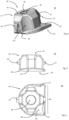
- figure 1 shows a lightweight fastener 10 from above in a 3D view.
- the two main components are the clip nut 40 installed in the cage 28, which forms the majority of the first leg 22 of the clip body 20.
- the first leg 22 is connected to the second leg 24 via a web 23 , which is functionally designed and referred to as a tongue 27 .
- the terms first leg 22, second leg 24 and connecting web 23 are primarily intended to be functional. Since the clip body 20 is constructed in one piece and these functional areas merge into one another, it is clear to the person skilled in the art that precise demarcation lines are neither useful nor necessary.
- figure 1 shows further details that can be provided in a series product from a structural point of view, such as recesses to save material, reinforcement ribs and gripping surfaces.
- FIG 2 12 is a top view of the clip body 20 of the lightweight fastener 10, ie the first leg 22.
- the structure of the cage 28 can be seen from above.
- the cage has a large opening 29 through the first leg 22 which allows parts of the second leg 24 and the tongue 27 to be viewed.
- the tongue 27 has a further opening 25 .
- the web 23 is shown in plan view.
- Two areas of the cage 28 have the openings 36 and 37 in the cage 28; they are indicated in dashed lines opposite one another in the longitudinal axis of the first leg 22. These openings are arranged parallel to the plane of extension of the first leg 22 .
- the figure 3 shows a side view of the clip body 20, again with the first leg 22, second leg 24 and connecting web 23.
- the cage 28 occupies the predominant part of the first leg 22. Between the cage 28 and the transition area to the web 23, the leg is equipped with a step that is oriented towards the inside of the clamp and provides an emergency contact surface 19.
- figure 1 shows the interaction of the emergency contact surface 19 and the stop edge 49 (cf. also figure 6 ).
- the opening 25 in the second leg 24 and the position of the opening 29 (first leg 22) are indicated by arrows.
- the opening 25 in the area of the tongue 27 is surrounded by a cut sleeve section 21, similar to a collar.
- FIG 4 shows a perspective view of a clip nut 40 as an isolated component. Its main components are the nut base 42 and the main body 44.
- the nut base 42 is shown as a substantially planar, plate-shaped base surface 43 with irregularly shaped edges.
- the planar base surface 43 (underside) transitions at one edge into the previously described chamfer 45.
- the main body 44 is shown as a basically polygonal body whose side walls 51, 51', 51",... are concave, interrupted by planar wall sections The side walls partially merge into slopes, which in turn open into the top surface 41.
- the central opening 46 is shown in the top surface with its internal thread 49.
- Two projections or lugs 56, 57 are attached to the main body, which serve as protection against loss (according to Mounting in the clip body. They come to lie in the openings 36, 37 in the mounted state.
- figure 5 shows a clip nut 40 in a schematic side view. It can be seen here that the nut base 42 has a flat base surface 43 ("underside"), while its upper side has a convex curvature.
- FIG. 14 is again a plan view of the clip nut from top surface 41.
- FIG. The irregular shape of the nut base 42 selected here can be seen. How to in synopsis of figure 1 and 6 recognizes, there are contact areas between the nut base and the receiving space 26 facing underside of the first leg 22 of the clip body 20. These support areas 47 and 48 are in figure 6 indicated by hatching. As also described above, because of the convexly curved surface of the nut base 42, the clip nut 40 can perform a rolling movement relative to the clip body.
- Feature 49 designates the stop edge, which (in the assembled state) can interact with the emergency contact surface 19 .
Landscapes
- Engineering & Computer Science (AREA)
- General Engineering & Computer Science (AREA)
- Mechanical Engineering (AREA)
- Connection Of Plates (AREA)
Claims (16)
- Élément de fixation de construction légère (10) avec un corps de clip (20) d'une seule pièce en matière plastique- le corps de clip (20) présentant la forme de base d'une pince- avec deux branches (22, 24) opposées, s'étendant dans la direction longitudinale- et une entretoise (23) reliant deux extrémités de branche opposées ;- avec un espace de réception (26) pour un composant en forme de plaque entre les branches (22, 24), qui est délimité d'un côté par l'entretoise (23) ;et un écrou de clip (40)- qui présente une base d'écrou (42) qui est conçue sensiblement en forme de plaque avec une surface de base plate (43) dirigée vers le côté intérieur de la pince ;- et un corps principal (44) qui repose sur la base d'écrou (42) et qui présente une surface supérieure (41) ainsi qu'une pluralité de parois latérales (51, 51', 52",...) qui s'étendent entre la base d'écrou (42) et la surface supérieure (41) ;- le corps principal (44) présentant une section transversale sensiblement polygonale parallèle à la base d'écrou (42) ;- et qui présente une ouverture centrale (46) qui s'étend à travers la base d'écrou (42), le corps principal (44) et la surface supérieure (41) ;dans lequel- une première branche (22) du corps de clip (20) présente une cage (28) constituée de plusieurs éléments de paroi (31, 31', 31",...), dans laquelle l'écrou de clip (40) est logé de manière mobile et flottante ;- la cage (28) présente au moins deux ouvertures de retenue (36, 37),- la deuxième branche (24) est conçue comme une surface d'appui plate en forme de languette (27) vers le côté intérieur de la pince,- la première branche dans la zone de la cage (28), la deuxième branche dans la zone de la surface d'appui plate en forme de languette (27) présentent chacune une ouverture (29, 25), qui sont alignées avec l'ouverture centrale (46) de l'écrou de clip (40) disposé dans la cage (28),caractérisé en ce que- la première branche (22) est conçue de telle sorte que la surface de base (43) de l'écrou de clip (40) est dirigée vers le côté intérieur de la pince et est conçue comme surface d'appui pour le contact direct avec le composant en forme de plaque ;- le corps principal (44) de l'écrou de clip (40) présente au moins deux ergots (56, 57) en forme de tenon qui s'engagent dans les ouvertures (36, 37) des éléments de paroi de la cage (28).
- Élément de fixation de construction légère selon la revendication 1, caractérisé en ce qu'un nombre n de parois latérales (51, 51', 51",...) du corps principal d'écrou de clip (44) sont courbées de manière concave, avec n=>3.
- Élément de fixation de construction légère selon les revendications 1 à 2, caractérisé en ce qu'au moins n éléments de paroi (31, 31', 31",...) de la cage (28) orientés vers l'intérieur sont courbés de manière convexe vers l'intérieur.
- Élément de fixation de construction légère selon les revendications 1 à 3, caractérisé en ce que les parois latérales (51, 51', 51",...) du corps principal d'écrou de clip (44) et les éléments de paroi (31, 31', 31",...) de la cage (28) sont opposés par paires.
- Élément de fixation de construction légère selon les revendications 2 à 4, caractérisé en ce que la courbure des parois latérales (51, 51', 51",...), respectivement des éléments de paroi (31, 31', 31",...), suit la forme de sections coniques, et peut donc être décrite comme étant en forme de segment de cercle, elliptique, parabolique ou hyperbolique en section transversale horizontale.
- Élément de fixation de construction légère selon les revendications 2 à 5, caractérisé en ce que la courbure des parois latérales (51, 51', 51",...), respectivement des éléments de paroi (31, 31', 31",...), est réalisée sous la forme d'arcs de cercle.
- Élément de fixation de construction légère selon la revendication 6, caractérisé en ce que les rayons des arcs de cercle pour les parois latérales concaves (51, 51', 51",...), respectivement les éléments de paroi convexes (31, 31', 31",...), sont choisis sensiblement égaux.
- Élément de fixation de construction légère selon les revendications 1 à 7, caractérisé en ce que l'ouverture centrale (46) de l'écrou de clip (40) présente un filetage intérieur (49).
- Élément de fixation de construction légère selon les revendications 1 à 8, caractérisé en ce que l'écrou de clip (20) est fabriqué d'une seule pièce en matière plastique, de préférence en une matière thermoplastique, en particulier en PEEK.
- Élément de fixation de construction légère selon les revendications 8 à 9, caractérisé en ce que la sortie du filetage (49) tournée vers la surface supérieure (41) est conçue de telle sorte qu'un élément de fixation vissé est bloqué par serrage.
- Élément de fixation de construction légère selon les revendications 1 à 10, caractérisé en ce que la base d'écrou (42) présente, sur sa face supérieure opposée à la surface de base (43), des zones d'appui (47, 48) qui ont une courbure concave et sont orientées de manière à permettre un mouvement de roulement ou de basculement de l'écrou de clip (40) le long de la première branche (22).
- Élément de fixation de construction légère selon les revendications 1 à 11, caractérisé en ce que la base d'écrou (42) présente un chanfrein (45) incliné par rapport à la surface de base.
- Élément de fixation de construction légère selon la revendication 12, caractérisé en ce que la base d'écrou (42) présente, sur le bord opposé au chanfrein (45), une arête de butée (49) qui, lorsque l'écrou de clip (40) est logé dans la cage (48), est disposée parallèlement et à distance en face d'une surface d'appui de secours (19).
- Élément de fixation de construction légère selon les revendications 1 à 13, caractérisé en ce que le corps de clip est réalisé d'une seule pièce en matière plastique, de préférence en une matière thermoplastique, en particulier en PEEK.
- Élément de fixation de construction légère selon les revendications 1 à 14, caractérisé en ce que le corps de clip est réalisé d'une seule pièce sous forme de moulage par injection à deux composants, le premier composant en matière plastique étant choisi plus élastique que le deuxième.
- Élément de fixation de construction légère selon la revendication 15, caractérisé en ce que le composant plus élastique est utilisé principalement dans la zone de la deuxième branche (22), respectivement de la languette (27), et dans la zone de l'entretoise (23).
Priority Applications (4)
| Application Number | Priority Date | Filing Date | Title |
|---|---|---|---|
| EP20152361.0A EP3851686B1 (fr) | 2020-01-17 | 2020-01-17 | Dispositif de fixation léger |
| PCT/EP2021/050790 WO2021144411A1 (fr) | 2020-01-17 | 2021-01-15 | Système de fixation pour construction légère |
| US17/793,078 US20230040255A1 (en) | 2020-01-17 | 2021-01-15 | Lightweight-construction fastener |
| CN202180007499.7A CN115003923A (zh) | 2020-01-17 | 2021-01-15 | 轻型结构紧固件 |
Applications Claiming Priority (1)
| Application Number | Priority Date | Filing Date | Title |
|---|---|---|---|
| EP20152361.0A EP3851686B1 (fr) | 2020-01-17 | 2020-01-17 | Dispositif de fixation léger |
Publications (2)
| Publication Number | Publication Date |
|---|---|
| EP3851686A1 EP3851686A1 (fr) | 2021-07-21 |
| EP3851686B1 true EP3851686B1 (fr) | 2023-03-29 |
Family
ID=69177037
Family Applications (1)
| Application Number | Title | Priority Date | Filing Date |
|---|---|---|---|
| EP20152361.0A Active EP3851686B1 (fr) | 2020-01-17 | 2020-01-17 | Dispositif de fixation léger |
Country Status (4)
| Country | Link |
|---|---|
| US (1) | US20230040255A1 (fr) |
| EP (1) | EP3851686B1 (fr) |
| CN (1) | CN115003923A (fr) |
| WO (1) | WO2021144411A1 (fr) |
Families Citing this family (1)
| Publication number | Priority date | Publication date | Assignee | Title |
|---|---|---|---|---|
| CN116557391B (zh) * | 2023-07-10 | 2023-09-12 | 浙江易锻精密机械有限公司 | 一种卡扣及冲压设备 |
Family Cites Families (14)
| Publication number | Priority date | Publication date | Assignee | Title |
|---|---|---|---|---|
| FR2649454B1 (fr) | 1989-07-06 | 1991-11-15 | Rapid Sa | Ecrou en forme de pince a montage sur le bord d'un panneau ou analogue |
| US5423646A (en) | 1993-02-24 | 1995-06-13 | Buell Industries, Inc. | U-nut |
| US6474917B2 (en) * | 2000-06-22 | 2002-11-05 | Jacques Gauron | Clip nuts |
| US6854941B2 (en) * | 2003-04-09 | 2005-02-15 | The Monadnock Company, Inc. | Clip nut |
| EP1784578B1 (fr) * | 2004-09-02 | 2008-03-19 | EJOT GmbH & Co. KG | Cale en forme de u |
| DE102005045723B3 (de) * | 2005-09-23 | 2007-05-03 | A. Raymond Et Cie | Befestigungsklammer |
| US8177466B2 (en) | 2007-06-13 | 2012-05-15 | The Monadnock Company | Apparatus and methods for fastening a panel or other components |
| US7959392B2 (en) * | 2008-05-16 | 2011-06-14 | Illinois Tool Works Inc. | U-nut fastener assembly |
| FR2934336B1 (fr) * | 2008-07-22 | 2010-09-17 | Lisi Automotive Rapid | Dispositif de pince a ecrou pouvant etre monte sur le bord d'un panneau ou analogue |
| US7648319B1 (en) * | 2008-11-12 | 2010-01-19 | Orlando Ochoa | Clip nut fastener |
| DE102016111933A1 (de) * | 2016-06-29 | 2018-01-04 | Sfs Intec Holding Ag | Leichtbaubefestiger mit Drahtgewindemutter |
| DE102016118676A1 (de) * | 2016-09-30 | 2018-04-05 | Sfs Intec Holding Ag | Leichtbaubefestiger |
| DE102016118657A1 (de) * | 2016-09-30 | 2018-04-05 | Sfs Intec Holding Ag | 2-komponenten clip |
| US11415164B2 (en) * | 2018-10-23 | 2022-08-16 | AlphaUSA | Retainer and a retainer and nut assembly |
-
2020
- 2020-01-17 EP EP20152361.0A patent/EP3851686B1/fr active Active
-
2021
- 2021-01-15 CN CN202180007499.7A patent/CN115003923A/zh active Pending
- 2021-01-15 WO PCT/EP2021/050790 patent/WO2021144411A1/fr active Application Filing
- 2021-01-15 US US17/793,078 patent/US20230040255A1/en active Pending
Also Published As
| Publication number | Publication date |
|---|---|
| WO2021144411A1 (fr) | 2021-07-22 |
| EP3851686A1 (fr) | 2021-07-21 |
| US20230040255A1 (en) | 2023-02-09 |
| CN115003923A (zh) | 2022-09-02 |
Similar Documents
| Publication | Publication Date | Title |
|---|---|---|
| DE3535210C2 (fr) | ||
| EP2003346B1 (fr) | Dispositif de fixation doté d'une égalisation de tolérance | |
| EP0414162B1 (fr) | Pièce d'écartement ajustable | |
| WO2012048686A1 (fr) | Écrou à cage | |
| EP0697267A1 (fr) | Dispositif de fixation pour un outil ou une pièce | |
| EP1780424A1 (fr) | Dispositif de fixation à compensation de tolérances | |
| DE19543830A1 (de) | Kunststoff-Befestigungselement, insbesondere für eine Fahrzeugverkleidung | |
| EP1626185A1 (fr) | Unité de réglage à ajuster la distance entre deux unités de construction | |
| EP3526476B1 (fr) | Clip à montage flottant | |
| WO2017032545A1 (fr) | Accouplement emboîtable en deux parties servant à l'assemblage de pièces | |
| EP0232917B1 (fr) | Procédé et accouplement et fixation pour le montage des affichages d'image | |
| EP4095396A1 (fr) | Dispositif de compensation de la tolérance | |
| EP3851686B1 (fr) | Dispositif de fixation léger | |
| EP1862356B1 (fr) | Clip de fixation | |
| EP1612432B1 (fr) | Dispositif de fixation pour habillage et méthode de fixation | |
| EP2871108B1 (fr) | Système de connexion destiné à fixer une partie de revêtement sur un véhicule, en particulier un véhicule ferroviaire, et véhicule sur rail correspondant | |
| DE102022134745A1 (de) | Befestigungsanordnung mit toleranzausgleich | |
| EP2304250A1 (fr) | Clip à vis | |
| EP1777791A2 (fr) | Pièce de finition et/ou de liaison | |
| DE102012112362B3 (de) | Ventil mit einer Befestigungseinrichtung | |
| DE3114283A1 (de) | "befestigungselement aus kunststoff, insbesondere zur loesbaren befestigung von flachen werkstuecken" | |
| EP1794461A1 (fr) | Assemblage par rivets et par vis d'une piece en matiere plastique avec une autre piece | |
| EP1394420A2 (fr) | Pièce à insérer dans une paroi, en particulier dans une carrosserie de véhicule | |
| EP4105497A1 (fr) | Dispositif de maintien et son procédé d'application | |
| DE102011050287A1 (de) | Klemmschraube sowie Schraubverbindung mit Klemmschraube |
Legal Events
| Date | Code | Title | Description |
|---|---|---|---|
| PUAI | Public reference made under article 153(3) epc to a published international application that has entered the european phase |
Free format text: ORIGINAL CODE: 0009012 |
|
| STAA | Information on the status of an ep patent application or granted ep patent |
Free format text: STATUS: THE APPLICATION HAS BEEN PUBLISHED |
|
| AK | Designated contracting states |
Kind code of ref document: A1 Designated state(s): AL AT BE BG CH CY CZ DE DK EE ES FI FR GB GR HR HU IE IS IT LI LT LU LV MC MK MT NL NO PL PT RO RS SE SI SK SM TR |
|
| STAA | Information on the status of an ep patent application or granted ep patent |
Free format text: STATUS: REQUEST FOR EXAMINATION WAS MADE |
|
| 17P | Request for examination filed |
Effective date: 20220121 |
|
| RBV | Designated contracting states (corrected) |
Designated state(s): AL AT BE BG CH CY CZ DE DK EE ES FI FR GB GR HR HU IE IS IT LI LT LU LV MC MK MT NL NO PL PT RO RS SE SI SK SM TR |
|
| RAP3 | Party data changed (applicant data changed or rights of an application transferred) |
Owner name: SFS GROUP INTERNATIONAL AG |
|
| GRAP | Despatch of communication of intention to grant a patent |
Free format text: ORIGINAL CODE: EPIDOSNIGR1 |
|
| STAA | Information on the status of an ep patent application or granted ep patent |
Free format text: STATUS: GRANT OF PATENT IS INTENDED |
|
| INTG | Intention to grant announced |
Effective date: 20230119 |
|
| GRAS | Grant fee paid |
Free format text: ORIGINAL CODE: EPIDOSNIGR3 |
|
| GRAA | (expected) grant |
Free format text: ORIGINAL CODE: 0009210 |
|
| STAA | Information on the status of an ep patent application or granted ep patent |
Free format text: STATUS: THE PATENT HAS BEEN GRANTED |
|
| AK | Designated contracting states |
Kind code of ref document: B1 Designated state(s): AL AT BE BG CH CY CZ DE DK EE ES FI FR GB GR HR HU IE IS IT LI LT LU LV MC MK MT NL NO PL PT RO RS SE SI SK SM TR |
|
| REG | Reference to a national code |
Ref country code: CH Ref legal event code: EP |
|
| REG | Reference to a national code |
Ref country code: DE Ref legal event code: R096 Ref document number: 502020002828 Country of ref document: DE |
|
| REG | Reference to a national code |
Ref country code: AT Ref legal event code: REF Ref document number: 1556857 Country of ref document: AT Kind code of ref document: T Effective date: 20230415 |
|
| REG | Reference to a national code |
Ref country code: IE Ref legal event code: FG4D Free format text: LANGUAGE OF EP DOCUMENT: GERMAN |
|
| REG | Reference to a national code |
Ref country code: LT Ref legal event code: MG9D |
|
| PG25 | Lapsed in a contracting state [announced via postgrant information from national office to epo] |
Ref country code: RS Free format text: LAPSE BECAUSE OF FAILURE TO SUBMIT A TRANSLATION OF THE DESCRIPTION OR TO PAY THE FEE WITHIN THE PRESCRIBED TIME-LIMIT Effective date: 20230329 Ref country code: NO Free format text: LAPSE BECAUSE OF FAILURE TO SUBMIT A TRANSLATION OF THE DESCRIPTION OR TO PAY THE FEE WITHIN THE PRESCRIBED TIME-LIMIT Effective date: 20230629 Ref country code: LV Free format text: LAPSE BECAUSE OF FAILURE TO SUBMIT A TRANSLATION OF THE DESCRIPTION OR TO PAY THE FEE WITHIN THE PRESCRIBED TIME-LIMIT Effective date: 20230329 Ref country code: LT Free format text: LAPSE BECAUSE OF FAILURE TO SUBMIT A TRANSLATION OF THE DESCRIPTION OR TO PAY THE FEE WITHIN THE PRESCRIBED TIME-LIMIT Effective date: 20230329 Ref country code: HR Free format text: LAPSE BECAUSE OF FAILURE TO SUBMIT A TRANSLATION OF THE DESCRIPTION OR TO PAY THE FEE WITHIN THE PRESCRIBED TIME-LIMIT Effective date: 20230329 |
|
| P01 | Opt-out of the competence of the unified patent court (upc) registered |
Effective date: 20230622 |
|
| REG | Reference to a national code |
Ref country code: NL Ref legal event code: MP Effective date: 20230329 |
|
| PG25 | Lapsed in a contracting state [announced via postgrant information from national office to epo] |
Ref country code: SE Free format text: LAPSE BECAUSE OF FAILURE TO SUBMIT A TRANSLATION OF THE DESCRIPTION OR TO PAY THE FEE WITHIN THE PRESCRIBED TIME-LIMIT Effective date: 20230329 Ref country code: NL Free format text: LAPSE BECAUSE OF FAILURE TO SUBMIT A TRANSLATION OF THE DESCRIPTION OR TO PAY THE FEE WITHIN THE PRESCRIBED TIME-LIMIT Effective date: 20230329 Ref country code: GR Free format text: LAPSE BECAUSE OF FAILURE TO SUBMIT A TRANSLATION OF THE DESCRIPTION OR TO PAY THE FEE WITHIN THE PRESCRIBED TIME-LIMIT Effective date: 20230630 Ref country code: FI Free format text: LAPSE BECAUSE OF FAILURE TO SUBMIT A TRANSLATION OF THE DESCRIPTION OR TO PAY THE FEE WITHIN THE PRESCRIBED TIME-LIMIT Effective date: 20230329 |
|
| PG25 | Lapsed in a contracting state [announced via postgrant information from national office to epo] |
Ref country code: SM Free format text: LAPSE BECAUSE OF FAILURE TO SUBMIT A TRANSLATION OF THE DESCRIPTION OR TO PAY THE FEE WITHIN THE PRESCRIBED TIME-LIMIT Effective date: 20230329 Ref country code: RO Free format text: LAPSE BECAUSE OF FAILURE TO SUBMIT A TRANSLATION OF THE DESCRIPTION OR TO PAY THE FEE WITHIN THE PRESCRIBED TIME-LIMIT Effective date: 20230329 Ref country code: PT Free format text: LAPSE BECAUSE OF FAILURE TO SUBMIT A TRANSLATION OF THE DESCRIPTION OR TO PAY THE FEE WITHIN THE PRESCRIBED TIME-LIMIT Effective date: 20230731 Ref country code: ES Free format text: LAPSE BECAUSE OF FAILURE TO SUBMIT A TRANSLATION OF THE DESCRIPTION OR TO PAY THE FEE WITHIN THE PRESCRIBED TIME-LIMIT Effective date: 20230329 Ref country code: EE Free format text: LAPSE BECAUSE OF FAILURE TO SUBMIT A TRANSLATION OF THE DESCRIPTION OR TO PAY THE FEE WITHIN THE PRESCRIBED TIME-LIMIT Effective date: 20230329 |
|
| PG25 | Lapsed in a contracting state [announced via postgrant information from national office to epo] |
Ref country code: SK Free format text: LAPSE BECAUSE OF FAILURE TO SUBMIT A TRANSLATION OF THE DESCRIPTION OR TO PAY THE FEE WITHIN THE PRESCRIBED TIME-LIMIT Effective date: 20230329 Ref country code: PL Free format text: LAPSE BECAUSE OF FAILURE TO SUBMIT A TRANSLATION OF THE DESCRIPTION OR TO PAY THE FEE WITHIN THE PRESCRIBED TIME-LIMIT Effective date: 20230329 Ref country code: IS Free format text: LAPSE BECAUSE OF FAILURE TO SUBMIT A TRANSLATION OF THE DESCRIPTION OR TO PAY THE FEE WITHIN THE PRESCRIBED TIME-LIMIT Effective date: 20230729 |
|
| REG | Reference to a national code |
Ref country code: DE Ref legal event code: R097 Ref document number: 502020002828 Country of ref document: DE |
|
| PG25 | Lapsed in a contracting state [announced via postgrant information from national office to epo] |
Ref country code: DK Free format text: LAPSE BECAUSE OF FAILURE TO SUBMIT A TRANSLATION OF THE DESCRIPTION OR TO PAY THE FEE WITHIN THE PRESCRIBED TIME-LIMIT Effective date: 20230329 Ref country code: CZ Free format text: LAPSE BECAUSE OF FAILURE TO SUBMIT A TRANSLATION OF THE DESCRIPTION OR TO PAY THE FEE WITHIN THE PRESCRIBED TIME-LIMIT Effective date: 20230329 |
|
| PLBE | No opposition filed within time limit |
Free format text: ORIGINAL CODE: 0009261 |
|
| STAA | Information on the status of an ep patent application or granted ep patent |
Free format text: STATUS: NO OPPOSITION FILED WITHIN TIME LIMIT |
|
| 26N | No opposition filed |
Effective date: 20240103 |
|
| PGFP | Annual fee paid to national office [announced via postgrant information from national office to epo] |
Ref country code: DE Payment date: 20240119 Year of fee payment: 5 |
|
| PG25 | Lapsed in a contracting state [announced via postgrant information from national office to epo] |
Ref country code: SI Free format text: LAPSE BECAUSE OF FAILURE TO SUBMIT A TRANSLATION OF THE DESCRIPTION OR TO PAY THE FEE WITHIN THE PRESCRIBED TIME-LIMIT Effective date: 20230329 |