EP3851616B1 - Transport anchor with strap - Google Patents
Transport anchor with strap Download PDFInfo
- Publication number
- EP3851616B1 EP3851616B1 EP20152603.5A EP20152603A EP3851616B1 EP 3851616 B1 EP3851616 B1 EP 3851616B1 EP 20152603 A EP20152603 A EP 20152603A EP 3851616 B1 EP3851616 B1 EP 3851616B1
- Authority
- EP
- European Patent Office
- Prior art keywords
- anchoring
- clevis
- strap
- limbs
- concrete
- Prior art date
- Legal status (The legal status is an assumption and is not a legal conclusion. Google has not performed a legal analysis and makes no representation as to the accuracy of the status listed.)
- Active
Links
- 238000004873 anchoring Methods 0.000 claims description 131
- 239000004567 concrete Substances 0.000 claims description 38
- 230000007704 transition Effects 0.000 claims description 25
- 238000004519 manufacturing process Methods 0.000 claims description 13
- 238000005452 bending Methods 0.000 claims description 12
- 238000000034 method Methods 0.000 claims description 9
- 125000006850 spacer group Chemical group 0.000 claims description 5
- 229910000831 Steel Inorganic materials 0.000 claims description 4
- 239000010959 steel Substances 0.000 claims description 4
- 239000003381 stabilizer Substances 0.000 claims 10
- 238000009434 installation Methods 0.000 description 13
- 238000004806 packaging method and process Methods 0.000 description 8
- 238000005304 joining Methods 0.000 description 3
- 238000003466 welding Methods 0.000 description 3
- 238000003780 insertion Methods 0.000 description 2
- 230000037431 insertion Effects 0.000 description 2
- 230000003993 interaction Effects 0.000 description 2
- JEIPFZHSYJVQDO-UHFFFAOYSA-N iron(III) oxide Inorganic materials O=[Fe]O[Fe]=O JEIPFZHSYJVQDO-UHFFFAOYSA-N 0.000 description 2
- 238000003860 storage Methods 0.000 description 2
- 239000002390 adhesive tape Substances 0.000 description 1
- 230000015572 biosynthetic process Effects 0.000 description 1
- 238000005266 casting Methods 0.000 description 1
- 230000008878 coupling Effects 0.000 description 1
- 238000010168 coupling process Methods 0.000 description 1
- 238000005859 coupling reaction Methods 0.000 description 1
- 238000005520 cutting process Methods 0.000 description 1
- 230000001419 dependent effect Effects 0.000 description 1
- 230000000694 effects Effects 0.000 description 1
- 238000007667 floating Methods 0.000 description 1
- 238000012856 packing Methods 0.000 description 1
- 230000035515 penetration Effects 0.000 description 1
- 239000011178 precast concrete Substances 0.000 description 1
- 230000036316 preload Effects 0.000 description 1
- 230000002787 reinforcement Effects 0.000 description 1
- 239000007858 starting material Substances 0.000 description 1
- 230000003068 static effect Effects 0.000 description 1
Images


Classifications
-
- E—FIXED CONSTRUCTIONS
- E04—BUILDING
- E04G—SCAFFOLDING; FORMS; SHUTTERING; BUILDING IMPLEMENTS OR AIDS, OR THEIR USE; HANDLING BUILDING MATERIALS ON THE SITE; REPAIRING, BREAKING-UP OR OTHER WORK ON EXISTING BUILDINGS
- E04G21/00—Preparing, conveying, or working-up building materials or building elements in situ; Other devices or measures for constructional work
- E04G21/14—Conveying or assembling building elements
- E04G21/142—Means in or on the elements for connecting same to handling apparatus
- E04G21/145—Means in or on the elements for connecting same to handling apparatus specific for hollow plates
-
- B—PERFORMING OPERATIONS; TRANSPORTING
- B25—HAND TOOLS; PORTABLE POWER-DRIVEN TOOLS; MANIPULATORS
- B25B—TOOLS OR BENCH DEVICES NOT OTHERWISE PROVIDED FOR, FOR FASTENING, CONNECTING, DISENGAGING OR HOLDING
- B25B5/00—Clamps
- B25B5/14—Clamps for work of special profile
- B25B5/145—Clamps for work of special profile for plates
Definitions
- the invention relates to a transport anchor, in particular for hollow walls or double or multiple concrete walls, each with opposing concrete shells according to claim 1.
- the invention also relates to a method for producing such a transport anchor according to claim 9.
- transport anchor filament anchor
- the transport anchor essentially comprises a clevis and a crossbar or a cross brace.
- the parallel, opposite ends of the load bracket serve as anchoring legs for embedding in concrete in a concrete shell. They are connected to one another by a center section of the yoke that is generally curved once or several times and are held apart or at a predetermined distance from one another by the cross brace. This is to prevent the anchoring legs from contracting and tearing out of the concrete shells when the wall is lifted.
- the cross brace is attached to the anchoring legs in a movable, displaceable manner or by means of welded connections or tacking, with the entire lifting bracket of the transport anchor being stiffened.
- a clevis comprising a clevis center section and the anchoring legs of the lifting anchor is often provided by bending rebar using a bending machine.
- a problem with such a manufacturing process is that the rebars used as the starting material are not always the same. Tolerances of the rebar exist with regard to the strength, the dimensions, in particular the diameter, the roundness and the dimensions of the ribs of the rebar. If these rebars are then processed into lifting anchors, each bent lifting anchor can have different external dimensions when measured afterwards. These deviations are amplified by manufacturing tolerances of the bending machine and temperature differences in the steel.
- the distance between the two anchoring legs is particularly affected by these deviations, since the loose anchoring legs can easily be bent during production, storage, transport or installation of the lifting anchor in the precast concrete plant. These deviations in the outer dimensions of the lifting anchor are undesirable and problematic for installation and operational safety.
- the anchoring legs are further conically bent, i.e. the lifting anchor becomes wider towards the anchoring leg end sections, the concrete cover on the outside of the concrete double wall falls below the required minimum thickness. This can result in rust damage to the transport anchor.
- the anchoring legs require a concrete cover of 10mm. Even a slight bending up of the anchoring leg, which results in a 1 mm increase in the distance between the end sections of the anchoring leg, reduces the concrete cover by a full 10%. If, on the other hand, the anchoring limbs are pressed together, the transport anchor becomes narrower towards the anchoring limb end sections and the distance between the anchoring limb end sections can be less than the length of the cross brace.
- the lifting anchors for concrete double walls also have an additional cross brace on the anchoring leg end sections, which is welded to the anchoring legs in the area of the anchoring leg end sections.
- the DE 10 2016 119352 A1 provides a lifting anchor with a where the cross brace is concrete.
- a fixing element can connect the anchor legs to one another, preferably by welding. This fixing element enables the anchoring legs to be shortened or prevents them from floating up.
- the object of the invention is to improve the operational safety of the known transport anchor and to reduce the risk of errors during installation.
- a lifting anchor with two anchoring legs which connects two concrete shells of a double wall, is usually assumed below.
- a clevis typically has two anchoring legs, with one anchoring leg each being cast or capable of being cast for casting in a concrete shell or concrete wall of a double wall.
- the clevis center section is preferably located in a space between the opposing concrete shells.
- the crossbar can also be arranged in this intermediate space and absorbs the pressure and/or tensile forces when lifting or erecting the double wall on the transport anchor and thus stabilizes the transport anchor when the load is picked up.
- the cross brace can be designed as a spacer device or other device for maintaining the distance between the anchoring legs.
- a holding device which also includes the anchoring legs of the transport anchor at at least two contact points, additionally stabilizes the individual sections of the load bracket and the cross brace in the load bracket.
- the desired shape of the lifting anchor set during manufacture can also be maintained during storage and installation, in particular through the interaction of the cross brace and holding device. This simplifies handling when installing the transport anchor in the double wall to be manufactured and increases installation safety.
- Releasable fastening means that the holding device can be removed without being destroyed before, after and/or during installation, or at least loses its holding power as a result of being destroyed.
- the holding device preferably comprises or encompasses an anchoring leg assigned to a first concrete shell and an anchoring leg assigned to a second concrete shell.
- Encompassing means that the holding device forms a form-fitting and/or frictional and/or material-locking holding connection with both anchoring legs, so that the anchoring legs are locked and fixed in a predetermined position relative to one another for installation.
- the one clevis width specified for operational safety is not exceeded in the area of the anchoring legs.
- the required concrete cover on the outside of the double wall can thus be maintained and rust damage to the lifting anchor can be avoided.
- the holding device forms a frictional holding contact with the anchoring leg assigned to the first concrete shell and/or the anchoring leg assigned to the second concrete shell.
- the anchoring legs run essentially parallel. Nevertheless, during the manufacture of the clevis when pre-bending an extruded body, provision can initially be made for the anchoring legs to run more or less conically in relation to one another and open towards the anchoring leg end sections. In other words, the distance between the anchoring legs increases starting from the transition curves towards the leg end sections. After inserting and possibly fastening the cross brace, the anchoring leg end sections are pressed inwards, ie towards the body axis, so that the anchoring legs align parallel to one another or close towards the anchoring leg end sections. This creates a pretension in the load bracket, which can be permanently maintained for transport and/or installation by the frictional holding contacts of the holding device.
- the anchoring limbs are pressed further outwards by a suitable holding device, so that the distance between the anchoring limb end sections increases further.
- the preload can be maintained, for example, by a holding device (see Fig.2a ) which encompasses or surrounds the cross brace and the clevis middle section.
- the holding device is designed as a band-like, preferably flexible and/or taut, holding band, for example a packaging band.
- the retaining strap is wrapped around the load bracket in the area of the anchoring legs at least once so that the anchoring legs are gripped from behind.
- the tether comes to rest with the anchoring limbs on the area of the anchoring limbs facing away from the body axis and maintains a pretension in the clevis which may be necessary for the desired alignment of the anchoring limbs.
- the retaining strap can be designed as an inexpensive packaging strap, which can be removed by cutting at any installation step.
- the anchoring limbs in particular the anchoring limb end sections, are preferably fixed and/or locked by the holding device in a predetermined position of the anchoring limbs relative to one another.
- a predetermined position means that, in particular in the area of the anchoring leg end sections, the width is neither exceeded nor fallen below a predetermined load bracket. This ensures that the penetration depth of the anchoring leg end sections into the concrete body of the concrete shell is maximum or corresponds to the desired amount. In particular, it is avoided that the anchoring leg distances in the area of the anchoring leg end sections are smaller than in the area of the cross brace or the transition curves and thus the transport anchor legs are not anchored deep enough in the concrete. The anchoring leg end sections remain precisely positioned by the holding device and the transport anchors can safely carry the load of the component.
- the cross brace or other spacer device is attached to the anchoring leg or legs in a sliding manner and/or in frictional engagement.
- a transition curve is formed between the middle section of the shackle and the at least two anchoring legs, with the cross brace in the area of the transition curves passing through a second holding device, in particular by a second holding strap, is held, the first holding device spanning the at least two anchoring legs in the region of the anchoring leg end sections.
- the anchoring legs usually transition into the middle section of the lifting anchor clevis via a transition curve, transition bend or transition kink.
- the cross brace is positioned in such a way that it adjoins, abuts or bears against the curved transition area of the middle section of the yoke. So that there is no need for welding or any other joining method for a non-detachable connection, the position of the cross brace is fixed by compressive forces which are exerted by both anchoring legs on the two end regions of the cross brace, with the compressive forces being essentially parallel to the longitudinal axis of the cross brace and perpendicular facing the anchoring legs.
- the compressive force is provided by both anchoring legs being pressed in the direction of the body axis of the transport anchor and the resultant tensioning force or prestressing in the strand body of the load clip being permanently fixed by a holding device in the area of the anchoring leg end sections until the holding device is removed or destroyed.
- the first holding device is a holding strap that encircles the two anchoring legs, i.e. grasps around or behind them, and can prevent the pretension generated in the clevis from loosening again.
- the cross brace can be held in the yoke by frictional retaining contacts and/or joining methods such as welding.
- a second retaining strap or other retaining device is tensioned to fix the position of the cross strut in contact with the cross strut and the clevis blank and/or the clevis.
- the cross brace is held in a predetermined position, preferably in the region of the transition curves, by the second retaining strap.
- additional joining methods for fastening the cross brace can be omitted.
- the tensioning force of the retaining strap resulting from the tensioning process presses the cross brace in the area of the transition curves against the middle section of the yoke. This creates a holding force of the transition curves on the cross brace, which prevents the cross brace from slipping sideways or radially in the transport anchor.
- the frictional contact is preferably realized at two contact points between the two end areas of the cross brace and the anchoring legs, in particular in the area of the transition curves, that is to say in the straight area of the attachment triangle for the attachment means. Since the blank clevis has previously been manufactured in such a way that the distance between the anchoring legs increases towards the end sections of the anchoring limbs, the realization of the contact contacts results in a pretension in the clevis. This pretension can be fixed, for example, by tightly wrapping the load bracket in the area of the anchoring leg with a packing tape.
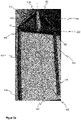
- figure 1 shows a transport anchor from the prior art with a clevis 100 made of highly ductile rebar, and a cross brace 200 made of a steel tube that is pressed flat in its end areas 201 .
- the one-piece yoke 100 with an approximately U-shaped basic shape, its rectilinear, parallel, opposite end sections each form an anchoring leg 101, which merges into a central section 103 of the yoke via a transition curve 102 in each case.
- the yoke middle section 103 connects the two anchoring legs 101, with the yoke middle section 103 external load bearing and/or means of transport, for example crane hooks (not shown), can be coupled or engaged.
- a body axis 107 of the transport anchor can essentially correspond to an axis of symmetry of the transport anchor, the clevis 100 and/or a mirror axis between the anchor legs 101 .
- the ends of the anchoring legs 101 facing away from the central section 103 of the yoke, the end sections 104 of the anchoring limbs, run parallel to one another, so that the width 105 of the yoke in the area of the end sections of the anchoring limb 104 corresponds to the width of the yoke 105 in the area of the transition curve 102.
- a predetermined anchoring leg distance 106 ie the distance between the anchoring legs 101, should not be undershot.
- the cross strut 200 is designed in its end areas 201 at the same time with guide recesses 202, in which the respective ribbed steel strand body of the anchoring leg 101 is accommodated with frictional engagement and slidingly displaceable against a frictional force.
- the arrangement shown is further provided with a holding device 300 in the form of a relatively wide packaging tape 301a, which is wrapped around the middle part of the yoke center section 103 and around a cross brace middle section 203 in order to hold the cross brace 200 and the clevis 100 in a certain relative position to one another.
- the wide side of the packaging tape that is visible to the outside can be used as an information carrier for the reproduction of various information 303 .
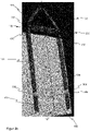
- Figure 2a shows a lifting anchor, in contrast to the lifting anchor according to FIG figure 1 the packaging tape or the retaining tape 301 is wound with tension around the middle part of the middle section 103 of the bracket and around the middle section of the cross brace 203, so that a frictional holding contact 304 is formed with the cross brace 200 and a frictional holding contact is formed with the middle section of the load bow 103 and the cross brace 200 in the region of the transition curves 102, a frictional contact 150 with the load bracket 100 is realized.
- the frictional contact 150 also contributes to keeping the anchoring legs 101 of the load clip 100 in a specific position relative to one another.
- Figure 2b shows a transport anchor with a first retaining strap 302 in the area of the anchoring limbs 101, in particular in the area of the anchoring limb end sections 104.
- the anchoring legs 101 are preferably initially aligned in such a way that the distance 106 between the anchoring legs 101 increases, starting from the transition curves 102 towards the end sections 104 of the legs.
- the anchoring leg end sections 104 are pressed inwards, ie towards the body axis 107, so that the anchoring legs 101 run parallel and contact contacts 150 are formed between the cross brace 200 and the transition curves 102.
- the first tether 302 is wound tightly at least once around the clevis 100 on the outside in the area of the anchoring legs 101, so that the anchoring legs 101 are gripped from behind.
- the tether 302 forms holding contacts 304 on a region of the respective anchoring leg 101 facing away from the body axis 107 and maintains the pretension in the clevis 100 , the pretension being necessary for the anchoring limb 101 to rest 150 on the cross brace 200 .
- Figure 2c combines the tether 301 out Figure 2a and the first tether 302 off Figure 2b .
- the subsequent assembly of the first tether 302 is facilitated, in particular for a manual assembly of the first tether 302.
- a total of four friction-locking holding contacts 304 are provided by two holding straps 301, 302, which hold the transport anchor in the desired position and ensure installation in accordance with the installation instructions.
- adhesive tapes can also be used.
- retaining straps 301, 302 can also be tightened in the transport anchor.
Description
Die Erfindung betrifft einen Transportanker, insbesondere für Hohlwände oder Doppel- oder Mehrfachbetonwände jeweils mit gegenüberliegenden Betonschalen nach Anspruch 1. Weiter betrifft die Erfindung ein Verfahren zur Herstellung eines derartigen Transportankers nach Anspruch 9.The invention relates to a transport anchor, in particular for hollow walls or double or multiple concrete walls, each with opposing concrete shells according to claim 1. The invention also relates to a method for producing such a transport anchor according to claim 9.
Es ist bspw. aus dem Produktkatalog
Von diesen Abweichungen ist vor allem der Abstand der beiden Verankerungsschenkel betroffen, da bei der Herstellung, bei der Lagerung, beim Transport oder beim Einbau des Transportankers im Betonfertigteilwerk die losen Verankerungsschenkel leicht verbogen werden können. Diese Abweichungen der Außenabmessungen des Transportankers sind unerwünscht und für die Einbau- und Betriebssicherheit problematisch.The distance between the two anchoring legs is particularly affected by these deviations, since the loose anchoring legs can easily be bent during production, storage, transport or installation of the lifting anchor in the precast concrete plant. These deviations in the outer dimensions of the lifting anchor are undesirable and problematic for installation and operational safety.
Werden die Verankerungsschenkel z.B. weiter konisch aufgebogen, also der Transportanker wird zu den Verankerungsschenkel-Endabschnitten hin breiter, unterschreitet die Betondeckung zur Außenseite der Betondoppelwand die geforderte Mindestdicke. Dadurch können Rostschäden am Transportanker entstehen. Die die Verankerungsschenkel benötigen nach Einbauanleitung eine Betonüberdeckung von 10mm. Bereits ein geringes Aufbiegen der Verankerungsschenkel, welches in einer Vergrößerung des Abstands der Verankerungsschenkel-Endabschnitte von einem 1 mm resultiert, verringert die Betondeckung um ganze 10%. Werden die Verankerungsschenkel hingegen zusammengedrückt, wird der Transportanker zu den Verankerungsschenkel-Endabschnitten hin enger und der Abstand der Verankerungsschenkel-Endabschnitte kann die Länge der Querstrebe unterschreiten. Dann besteht die Gefahr, dass der Verankerungsschenkel nicht tief genug in den Bewehrungskorb eintaucht und folglich nicht tief genug im Beton verankert ist. Dadurch besteht die Möglichkeit beim Transport der Doppelwand, dass der Transportanker die Last des Bauteiles nicht sicher trägt und ausreißt.If, for example, the anchoring legs are further conically bent, i.e. the lifting anchor becomes wider towards the anchoring leg end sections, the concrete cover on the outside of the concrete double wall falls below the required minimum thickness. This can result in rust damage to the transport anchor. According to the installation instructions, the anchoring legs require a concrete cover of 10mm. Even a slight bending up of the anchoring leg, which results in a 1 mm increase in the distance between the end sections of the anchoring leg, reduces the concrete cover by a full 10%. If, on the other hand, the anchoring limbs are pressed together, the transport anchor becomes narrower towards the anchoring limb end sections and the distance between the anchoring limb end sections can be less than the length of the cross brace. Then there is a risk that the anchoring leg does not dip deep enough into the reinforcement cage and is consequently not anchored deep enough in the concrete. As a result, when transporting the double wall, there is a possibility that the transport anchor will not safely bear the load of the component and will tear out.
Im Stand der Technik, bspw. der
Die
Der Erfindung liegt die Aufgabe zugrunde, bei dem bekannten Transportanker die Betriebssicherheit zu verbessern und die Gefahr von Fehlern beim Einbau zu vermindern.The object of the invention is to improve the operational safety of the known transport anchor and to reduce the risk of errors during installation.
Zur Lösung werden der im Anspruch 1 angegebene Transportanker und das im Anspruch 9 angegebene Herstellungsverfahren für Transportanker mit Querstrebe vorgeschlagen. Optionale Ausgestaltungen der Erfindung ergeben sich aus den abhängigen Ansprüchen.The lifting anchor specified in claim 1 and the manufacturing method specified in claim 9 for lifting anchors with a cross brace are proposed as a solution. Optional refinements of the invention result from the dependent claims.
Die Erfindung betrifft einen Transportanker nach Anspruch 1, insbesondere für Hohlwände oder Doppel- oder Mehrfach-Betonwände jeweils mit gegenüberliegenden Betonschalen, wobei der Transportanker folgendes aufweist:
- Einen Lastbügel mit mindestens zwei Verankerungsschenkeln, wobei mindestens ein Verankerungsschenkel je einer Betonschale oder Betonwand zuordenbar ist.
- Einen Lastbügel-Mittelabschnitt, über welchen die mindestens zwei Verankerungsschenkel miteinander verbunden sind, wobei mit dem Lastbügel-Mittelabschnitt externe Lastaufnahme- und/oder Transportmittel koppelbar oder in Eingriff bringbar sind.
- Mindestens eine Querstrebe oder sonstige Abstandhalteeinrichtung, welche zur Aufnahme von Druck- oder Zugbelastungen zwischen den Verankerungsschenkeln quer oder schräg bezüglich einer Längsrichtung des oder der Verankerungsschenkel oder einer Körperachse des Transportankers angeordnet ist.
- Mindestens eine erste Halteeinrichtung, wobei die erste Halteeinrichtung die mindestens zwei Verankerungsschenkel, vorzugsweise lösbar, umfasst.
- A clevis with at least two anchoring legs, with at least one anchoring leg being assignable to a concrete shell or concrete wall.
- A central section of the shackle, via which the at least two anchoring legs are connected to one another, with external load handling and/or transport means being able to be coupled or engaged with the central section of the shackle.
- At least one transverse strut or other spacer device, which is arranged transversely or obliquely with respect to a longitudinal direction of the anchoring leg(s) or a body axis of the transport anchor to absorb pressure or tensile loads between the anchoring legs.
- At least one first holding device, wherein the first holding device comprises the at least two anchoring legs, preferably in a detachable manner.
Für ein erleichtertes Verständnis wird nachstehend meist von einem Transportanker mit zwei Verankerungsschenkeln ausgegangen, der zwei Betonschalen einer Doppelwand miteinander verbindet. Ein Lastbügel weist typischerweise zwei Verankerungsschenkel auf, wobei je ein Verankerungsschenkel zum Eingießen in je eine Betonschale oder Betonwand einer Doppelwand eingegossen ist oder eingegossen werden kann. Der Lastbügel-Mittelabschnitt ist vorzugsweise in einem Zwischenraum zwischen den gegenüberliegenden Betonschalen angeordnet. Die Querstrebe kann ebenfalls in diesem Zwischenraum angeordnet sein und nimmt die Druck- und/oder Zugkräfte beim Anheben oder Aufrichten der Doppelwand am Transportanker auf und stabilisiert damit den Transportanker bei der Lastaufnahme. Gleichzeitig kann die Querstrebe als eine Abstandhalteeinrichtung oder sonstige Einrichtung zum Halten des Abstands der Verankerungsschenkel ausgebildet sein. Sie ist verschiebbar oder fest mit dem Lastbügel verbunden und hält insbesondere die Verankerungsschenkel des Lastbügels in einem bei der Herstellung des Transportankers eingestellten exakten Abstand relativ zueinander. Eine Halteeinrichtung, welche zusätzlich die Verankerungsschenkel des Transportankers an mindestens zwei Anlagepunkten umfasst, stabilisiert die einzelnen Abschnitte des Lastbügels und die Querstrebe im Lastbügel zusätzlich. Insbesondere durch Zusammenwirken von Querstrebe und Halteeinrichtung kann die gewünschte und bei der Herstellung eingestellte Form des Transportankers auch während der Lagerung und dem Einbau erhalten werden. Damit wird die Handhabung beim Einbau des Transportankers in die zu fertigende Doppelwand vereinfacht und die Einbausicherheit erhöht. Lösbare Befestigung heiß, dass die Halteeinrichtung vor, nach und/oder während dem Einbau zerstörungsfrei entfernt werden kann oder zumindest durch Zerstören ihre Haltkraft verliert.To make things easier to understand, a lifting anchor with two anchoring legs, which connects two concrete shells of a double wall, is usually assumed below. A clevis typically has two anchoring legs, with one anchoring leg each being cast or capable of being cast for casting in a concrete shell or concrete wall of a double wall. The clevis center section is preferably located in a space between the opposing concrete shells. The crossbar can also be arranged in this intermediate space and absorbs the pressure and/or tensile forces when lifting or erecting the double wall on the transport anchor and thus stabilizes the transport anchor when the load is picked up. At the same time, the cross brace can be designed as a spacer device or other device for maintaining the distance between the anchoring legs. It is slidably or fixedly connected to the clevis and, in particular, keeps the anchoring legs of the clevis relative to one another at an exact distance that was set when the transport anchor was manufactured. A holding device, which also includes the anchoring legs of the transport anchor at at least two contact points, additionally stabilizes the individual sections of the load bracket and the cross brace in the load bracket. The desired shape of the lifting anchor set during manufacture can also be maintained during storage and installation, in particular through the interaction of the cross brace and holding device. This simplifies handling when installing the transport anchor in the double wall to be manufactured and increases installation safety. Releasable fastening means that the holding device can be removed without being destroyed before, after and/or during installation, or at least loses its holding power as a result of being destroyed.
Vorzugsweise umfasst oder umgreift die Halteeinrichtung einen einer ersten Betonschale zugeordneten Verankerungsschenkel und einen einer zweiten Betonschale zugeordneten Verankerungsschenkel.The holding device preferably comprises or encompasses an anchoring leg assigned to a first concrete shell and an anchoring leg assigned to a second concrete shell.
Umfassen heißt, dass die Halteeinrichtung eine form- und/oder reib- und/oder stoffschlüssige Halteverbindung mit beiden Verankerungsschenkeln ausbildet, sodass die Verankerungsschenkel in einer für den Einbau vorgegebenen Position relativ zueinander arretiert und fixiert sind. Damit wird insbesondere im Zusammenwirken der Halteverbindung mit der Querstrebe verhindert, dass die eine für die Betriebssicherheit vorgegebene Lastbügelbreite im Bereich der Verankerungsschenkel nicht überschritten wird. Die geforderte Betondeckung zur Außenseite der Doppelwand kann damit eingehalten und Rostschäden am Transportanker können vermieden werden. Weiter wird verhindert, dass ein vorgegebener Abstand zwischen den Verankerungsschenkeln unterschritten wird. Dadurch wird auch eine Betondeckung zum Zwischenraum der Doppelwand eingehalten und ein Ausreißen der Verankerungsschenkel beim Anheben oder Aufrichten der Doppelwand verhindert.Encompassing means that the holding device forms a form-fitting and/or frictional and/or material-locking holding connection with both anchoring legs, so that the anchoring legs are locked and fixed in a predetermined position relative to one another for installation. In this way, in particular in the interaction of the holding connection with the cross brace, it is prevented that the one clevis width specified for operational safety is not exceeded in the area of the anchoring legs. The required concrete cover on the outside of the double wall can thus be maintained and rust damage to the lifting anchor can be avoided. Furthermore, it is prevented that the distance between the anchoring legs falls below a predetermined value. As a result, a concrete cover is maintained in the space between the double wall and the anchoring legs are prevented from being torn out when the double wall is lifted or erected.
In einer bevorzugten Ausführungsform der Erfindung bildet die Halteeinrichtung einen reibschlüssigen Haltekontakt mit dem der ersten Betonschale zugeordneten Verankerungsschenkel und/oder dem der zweiten Betonschale zugeordneten Verankerungsschenkel aus.In a preferred embodiment of the invention, the holding device forms a frictional holding contact with the anchoring leg assigned to the first concrete shell and/or the anchoring leg assigned to the second concrete shell.
In dem gefertigten Transportanker ist vorgesehen, dass die Verankerungsschenkel im Wesentlichen parallel verlaufen. Gleichwohl kann während der Herstellung des Lastbügels beim Vorbiegen eines Strangkörpers zunächst vorgesehen sein, dass die Verankerungsschenkel quasi konisch zueinander verlaufen und sich zu den Verankerungsschenkel-Endabschnitten hin öffnen. In anderen Worten, der Abstand zwischen den Verankerungsschenkeln vergrößert sich ausgehend von den Übergangskrümmungen hin zu den Schenkelendabschnitten. Nach dem Einsetzen und ggf. Befestigen der Querstrebe werden die Verankerungsschenkel-Endabschnitte nach innen, d.h. zur Körperachse gedrückt, sodass sich die Verankerungsschenkel parallel zueinander ausrichten oder sich zu den Verankerungsschenkel-Endabschnitten hin schließen. Dadurch entsteht eine Vorspannung in dem Lastbügel, die durch die reibschlüssigen Haltekontakte der Halteeinrichtung dauerhaft für den Transport und/oder den Einbau aufrechterhalten werden kann. Alternativ werden die Verankerungsschenkel durch eine geeignete Halteeinrichtung weiter nach außen gedrückt, sodass sich der Abstand zwischen den Verankerungsschenkel-Endabschnitten weiter vergrößert. In diesem Fall kann die Vorspannung bspw. durch eine Halteeinrichtung aufrechterhalten werden (siehe
Erfindungsgemäß ist die Halteeinrichtung als bandartiges, vorzugsweise flexibles und/oder straff gespanntes, Halteband, bspw. ein Verpackungsband, ausgebildet.According to the invention, the holding device is designed as a band-like, preferably flexible and/or taut, holding band, for example a packaging band.
Das Halteband wird mindestens einmal außen um den Lastbügel im Bereich der Verankerungsschenkel gewickelt, sodass die Verankerungsschenkel hintergriffen werden. Das Halteband kommt mit den Verankerungsschenkeln an dem der Körperachse abgewandten Bereich der Verankerungsschenkel zur Anlage und erhält eine Vorspannung in dem Lastbügel aufrecht, welche zur gewünschten Ausrichtung der Verankerungsschenkel notwendig sein kann. Das Halteband kann als kostengünstiges Verpackungsband ausgebildet sein, welches bei jedem beliebigen Einbauschritt durch Zerschneiden beseitigt werden kann.The retaining strap is wrapped around the load bracket in the area of the anchoring legs at least once so that the anchoring legs are gripped from behind. The tether comes to rest with the anchoring limbs on the area of the anchoring limbs facing away from the body axis and maintains a pretension in the clevis which may be necessary for the desired alignment of the anchoring limbs. The retaining strap can be designed as an inexpensive packaging strap, which can be removed by cutting at any installation step.
Vorzugsweise sind die Verankerungsschenkel, insbesondere die Verankerungsschenkel-Endabschnitte, durch die Halteeinrichtung in einer vorbestimmten Position der Verankerungsschenkel relativ zueinander fixiert und/oder arretiert.The anchoring limbs, in particular the anchoring limb end sections, are preferably fixed and/or locked by the holding device in a predetermined position of the anchoring limbs relative to one another.
Vorbestimmte Position der heißt, dass insbesondere im Bereich der Verankerungsschenkel-Endabschnitte eine vorgegebene Lastbügelbreite weder über- noch unterschritten wird. Dadurch ist gewährleistet, dass die Eindringtiefe der Verankerungsschenkel-Endabschnitte in den Betonkörper der Betonschale maximal ist bzw. dem gewünschten Betrag entspricht. Es wird insbesondere vermieden, dass die Verankerungsschenkelabstände im Bereich der Verankerungsschenkel-Endabschnitte kleiner sind als im Bereich der Querstrebe bzw. der Übergangskrümmungen und damit die Transportankerschenkel nicht tief genug im Beton verankert sind. Durch die Halteeinrichtung bleiben die Verankerungsschenkel-Endabschnitte exakt positioniert und die Transportanker können die Last des Bauteils sicher tragen.A predetermined position means that, in particular in the area of the anchoring leg end sections, the width is neither exceeded nor fallen below a predetermined load bracket. This ensures that the penetration depth of the anchoring leg end sections into the concrete body of the concrete shell is maximum or corresponds to the desired amount. In particular, it is avoided that the anchoring leg distances in the area of the anchoring leg end sections are smaller than in the area of the cross brace or the transition curves and thus the transport anchor legs are not anchored deep enough in the concrete. The anchoring leg end sections remain precisely positioned by the holding device and the transport anchors can safely carry the load of the component.
In einer bevorzugten Ausführungsform der Erfindung ist die Querstrebe oder sonstige Abstandhalteeinrichtung an dem oder den Verankerungsschenkeln gleitend verschiebbar und/oder in reibschlüssiger Anlage angebracht.In a preferred embodiment of the invention, the cross brace or other spacer device is attached to the anchoring leg or legs in a sliding manner and/or in frictional engagement.
Damit ist die Verbindung oder Kopplung der Querstrebe mit den Verankerungsschenkeln vereinfacht, indem der Strangkörper des Verankerungsschenkels von der Querstrebe durch je eine axialen Gleitführung (d.h. in Längsrichtung des Strangkörpers oder Verankerungsschenkels) in den Endbereichen der Querstrebe mit Reibschluss bzw. Haftreibung erfasst ist. Ein seitliches oder radiales Verschieben oder Verrücken des Strangkörpers ist durch den entgegenstehenden Formschluss innerhalb der Gleitführung unterbunden, die durch die Querstrebe in deren Endbereichen vorzugsweise quer zu deren Längsrichtung verläuft. Für relativ aufwändige Schweißverbindungen oder sonstige stoffschlüssige Verbindungen besteht keine Notwendigkeit mehr. Für weitere Merkmale zur Ausbildung einer gleitend verschiebbaren Querstrebe und zu deren Anordnung wird auf die noch nicht veröffentlichte Anmeldung (Aktenzeichen:
In einer optionalen Weiterbildung ist zwischen dem Lastbügel-Mittelabschnitt und den mindestens zwei Verankerungsschenkeln jeweils eine Übergangskrümmung ausgebildet, wobei die Querstrebe im Bereich der Übergangskrümmungen durch eine zweite Halteeinrichtung, insbesondere durch ein zweites Halteband, gehalten ist, wobei die erste Halteeinrichtung die mindestens zwei Verankerungsschenkel im Bereich der Verankerungsschenkel-Endabschnitte umspannt.In an optional development, a transition curve is formed between the middle section of the shackle and the at least two anchoring legs, with the cross brace in the area of the transition curves passing through a second holding device, in particular by a second holding strap, is held, the first holding device spanning the at least two anchoring legs in the region of the anchoring leg end sections.
Üblicherweise gehen bei bekannten Transportankern die Verankerungsschenkel über je eine Übergangskrümmung, Übergangsbiegung oder einen Übergangsknick in den Mittelabschnitt des Transportanker-Lastbügels über. Damit kombiniert ist im Rahmen einer optionalen Erfindungsausbildung, dass die Querstrebe derart positioniert ist, dass sie an den gekrümmten Übergangsbereich des Lastbügel-Mittelabschnitts angrenzt, anstößt oder anliegt. Damit auf ein Verschweißen oder ein sonstiges Fügeverfahren für eine nicht lösbare Verbindung verzichtet werden kann, erfolgt die Lagefestlegung der Querstrebe durch Druckkräfte, die von beiden Verankerungsschenkeln auf die beiden Endbereiche der Querstrebe ausgeübt werden, wobei die Druckkräfte im Wesentlichen parallel zur Längsachse der Querstrebe und senkrecht zu den Verankerungsschenkeln gerichtet sind. Die Druckkraft wird bereitgestellt, indem beide Verankerungsschenkel in Richtung der Körperachse des Transportankers gedrückt werden und die dadurch erzeugte Spannkraft bzw. Vorspannung im Strangkörper des Lastbügels durch eine Halteeinrichtung im Bereich der Verankerungsschenkel-Endabschnitte dauerhaft und bis zu einem Entfernen oder Zerstören der Halteeinrichtung fixiert wird. Die erste Halteeinrichtung ist ein Halteband, dass die beiden Verankerungsschenkel umspannen, d.h. umgreifen bzw. hintergreifen, und verhindern kann, dass sich die im Lastbügel erzeugte Vorspannung wieder löst.In the case of known lifting anchors, the anchoring legs usually transition into the middle section of the lifting anchor clevis via a transition curve, transition bend or transition kink. In combination with this, within the scope of an optional embodiment of the invention, the cross brace is positioned in such a way that it adjoins, abuts or bears against the curved transition area of the middle section of the yoke. So that there is no need for welding or any other joining method for a non-detachable connection, the position of the cross brace is fixed by compressive forces which are exerted by both anchoring legs on the two end regions of the cross brace, with the compressive forces being essentially parallel to the longitudinal axis of the cross brace and perpendicular facing the anchoring legs. The compressive force is provided by both anchoring legs being pressed in the direction of the body axis of the transport anchor and the resultant tensioning force or prestressing in the strand body of the load clip being permanently fixed by a holding device in the area of the anchoring leg end sections until the holding device is removed or destroyed. The first holding device is a holding strap that encircles the two anchoring legs, i.e. grasps around or behind them, and can prevent the pretension generated in the clevis from loosening again.
Eigenständiger Erfindungsschutz wird beansprucht für ein Verfahren gemäß Anspruch 9 zur Herstellung eines Transportankers, insbesondere eines Transportankers in einer der beschriebenen Ausführungen. Das Verfahren kennzeichnet sich durch folgende Schritte:
- Bereitstellen eines Lastbügel-Strangkörpers, vorzugsweise aus Betonrippenstahl, zur Herstellung des Lastbügels,
- Biegen oder Vorbiegen des Lastbügel-Strangkörpers zum Herstellen eines Lastbügels oder eines Lastbügelrohlings mit einer etwa U-förmigen Grundform unter Ausbildung von zwei Verankerungsschenkeln, einem zwischen den beiden Verankerungsschenkeln angeordneten Lastbügel-Mittelabschnitt und zwischen dem Lastbügel-Mittelabschnitt und den beiden Verankerungsschenkeln angeordneten Übergangskrümmungen,
- Einsetzen einer Querstrebe zwischen die Verankerungsschenkel, insbesondere zwischen die Übergangskrümmungen,
- Spannen eines ersten Haltebands oder einer sonstigen, vorzugsweise strangartigen, Halteeinrichtung, zur Lage-Festlegung der Verankerungsschenkel.
- Provision of a shackle string body, preferably made of rebar, for the production of the shackle,
- Bending or pre-bending the shackle string body to produce a shackle or a shackle blank with an approximately U-shaped basic shape while forming two anchoring legs, a shackle middle section arranged between the two anchoring legs and transition curves arranged between the middle section of the clevis and the two anchoring legs,
- Insertion of a cross brace between the anchoring legs, in particular between the transition bends,
- Tensioning of a first retaining strap or another, preferably strand-like, retaining device to fix the position of the anchoring legs.
Durch ein Anbringen des Haltebands in einem späten und/oder abschließenden Fertigungsschritt können Fertigungstoleranzen beim Biegen und/oder Vorbiegen des Strangkörpers und dem Einsetzen der Querstrebe ausgeglichen werden, womit die Fertigung vereinfacht und die Qualität der damit gefertigten Transportanker gesteigert wird. Die Querstrebe kann im Lastbügel durch reibschlüssige Haltekontakte und/oder Fügeverfahren, wie z.B. Verschweißen, gehalten werden. Vorzugsweise wird nach oder während dem Einsetzen der Querstrebe ein zweites Halteband oder eine sonstige Halteeinrichtung zur Lage-Festlegung der Querstrebe in Anlage mit der Querstrebe und dem Lastbügelrohling und/oder dem Lastbügel gespannt.By attaching the tether in a late and/or final manufacturing step, manufacturing tolerances when bending and/or pre-bending the extruded body and inserting the cross brace can be compensated for, which simplifies manufacturing and increases the quality of the lifting anchor manufactured with it. The cross brace can be held in the yoke by frictional retaining contacts and/or joining methods such as welding. Preferably, after or during the insertion of the cross strut, a second retaining strap or other retaining device is tensioned to fix the position of the cross strut in contact with the cross strut and the clevis blank and/or the clevis.
Durch das zweite Halteband wird die Querstrebe in einer vorbestimmten Position, vorzugsweise im Bereich der Übergangskrümmungen gehalten. Dadurch können zusätzliche Fügeverfahren zum Befestigen der Querstrebe entfallen. Die durch den Spannvorgang entstehende Spannkraft des Haltebands drückt die Querstrebe im Bereich der Übergangskrümmungen gegen den Lastbügel-Mittelabschnitt. Damit wird eine Haltekraft der Übergangskrümmungen auf die Querstrebe erzeugt, die ein seitliches oder radiales Verrutschen der Querstrebe im Transportanker verhindert.The cross brace is held in a predetermined position, preferably in the region of the transition curves, by the second retaining strap. As a result, additional joining methods for fastening the cross brace can be omitted. The tensioning force of the retaining strap resulting from the tensioning process presses the cross brace in the area of the transition curves against the middle section of the yoke. This creates a holding force of the transition curves on the cross brace, which prevents the cross brace from slipping sideways or radially in the transport anchor.
Das erfindungsgemäße Verfahren weist die weiteren Schritte auf, dass
- vor oder während dem Spannen eines ersten Haltebands oder einer sonstigen Halteeinrichtung die beiden Verankerungsschenkel unter Ausbildung einer Vorspannung in dem Lastbügelrohling in eine, vorzugsweise reibschlüssige, Anlage mit der Querstrebe bewegt werden und
- zur Lage-Festlegung der Verankerungsschenkel in dieser Anlage das erste Halteband um die Verankerungsschenkel gespannt wird.
- before or during the tensioning of a first retaining strap or other retaining device, the two anchoring legs are moved into a, preferably frictionally engaged, contact with the transverse strut while forming a pretension in the load bar blank and
- to determine the position of the anchoring leg in this system, the first retaining strap is stretched around the anchoring leg.
Die reibschlüssige Anlage ist vorzugsweise an zwei Anlagekontakten zwischen den beiden Endbereichen der Querstrebe und den Verankerungsschenkeln, insbesondere im Bereich der Übergangskrümmungen, also quasi im geraden Bereich des Anschlagdreiecks für das Anschlagmittel, realisiert. Da der Lastbügelrohling zuvor so gefertigt worden ist, dass sich der Verankerungsschenkelabstand zu den Verankerungsschenkel-Endabschnitten hin vergrößert, entsteht durch die Realisierung der Anlagekontakte eine Vorspannung im Lastbügel. Bspw. durch spannendes Umwickeln des Lastbügels im Bereich der Verankerungsschenkel mit einem Verpackungsband kann diese Vorspannung fixiert werden.The frictional contact is preferably realized at two contact points between the two end areas of the cross brace and the anchoring legs, in particular in the area of the transition curves, that is to say in the straight area of the attachment triangle for the attachment means. Since the blank clevis has previously been manufactured in such a way that the distance between the anchoring legs increases towards the end sections of the anchoring limbs, the realization of the contact contacts results in a pretension in the clevis. This pretension can be fixed, for example, by tightly wrapping the load bracket in the area of the anchoring leg with a packing tape.
Weitere Einzelheiten, Merkmale und Wirkungen auf der Basis der Erfindung ergeben sich aus der nachfolgenden Beschreibung von drei Ausführungsbeispielen der Erfindung sowie aus den Zeichnungen. Die Zeichnungen zeigen in:
-
Figur 1 und2a den Transportanker in je einer beispielhaften Ausführungsform aus dem Stand der Technik in einer perspektivischen Ansicht; -
Figuren 2b-2c den Transportanker in zwei beispielhaften erfindungsgemäßen Ausführungsformen in einer perspektivischen Ansicht.
-
figure 1 and2a the transport anchor in an exemplary embodiment from the prior art in a perspective view; -
Figures 2b-2c the transport anchor in two exemplary embodiments according to the invention in a perspective view.
Die Figuren sind lediglich beispielhafter Natur und dienen nur dem Verständnis der Erfindung. Die gleichen Elemente sind mit denselben Bezugszeichen versehen.The figures are merely of an exemplary nature and serve only to understand the invention. The same elements are provided with the same reference numbers.
- 100100
- Lastbügelload bracket
- 101101
- Verankerungsschenkelanchoring legs
- 102102
- Übergangskrümmungtransition curvature
- 103103
- Lastbügel-Mittelabschnitt bzw. BügelmittelabschnittCentral section of the shackle or central section of the shackle
- 104104
- Verankerungsschenkel-Endabschnitteanchor leg end sections
- 105105
- Lastbügelbreiteyoke width
- 106106
- Verankerungsschenkelabstandanchor leg spacing
- 107107
- Körperachse, insbesondere SymmetrieachseBody axis, in particular axis of symmetry
- 150150
- Anlage, insbesondere reibschlüssiger AnlagekontaktSystem, in particular frictional system contact
- 200200
- Querstrebecross brace
- 201201
- Endbereich, insbesondere abgeflachtEnd area, especially flattened
- 202202
- Führungsaussparungguide recess
- 203203
- Querstreben-MittelabschnittCrossbar center section
- 300300
- Halteeinrichtungholding device
- 301301
- Zweites Halteband, insbesondere VerpackungsbandSecond retaining strap, in particular packaging strap
- 302302
- Erstes Halteband, insbesondere VerpackungsbandFirst retaining strap, in particular packaging strap
- 303303
- Informationeninformation
- 304304
- Haltekontakt, insbesondere reibschlüssigRetaining contact, in particular frictionally
Claims (11)
- A transportation anchor, in particular for hollow walls or double or multiple concrete walls, each with opposing concrete shells, wherein the transportation anchor has the following:- a clevis (100) with at least two anchoring limbs (101), wherein at least one anchoring limb (101) can be assigned to a concrete shell or concrete wall,- a clevis centre section (103), via which the at least two anchoring limbs (101) are connected to one another, wherein external load-bearing and/or transport means can be coupled to or brought into engagement with the clevis centre section (103),- at least one stabiliser bar (200) or other spacer device, which is arranged to absorb pressure or tensile stresses between the anchoring limbs (101), transverse or inclined in respect of a longitudinal axis of the anchoring limb(s) (101) or a body axis (107) of the transportation anchor,- at least one first holding device (300) which is formed as a ribbon-shaped strap (302),characterised in that
the first strap (302) comprises the at least two anchoring limbs (101). - The transportation anchor according to claim 1,
characterised in that
at least one second holding device (300) is formed as a ribbon-shaped second strap (301) and comprises the clevis centre section (103) and the stabiliser bar (200). - The transportation anchor according to one of claims 1 or 2,
characterised in that
the strap(s) (301, 302) is (are) formed to be flexible or taut. - The transportation anchor according to one of the preceding claims,
characterised in that
the first strap (302) comprises an anchoring limb (101) which can be assigned to a first concrete shell and an anchoring limb (101) which can be assigned to a second concrete shell. - The transportation anchor according to the preceding claim,
characterised in that
the first strap (302) forms a friction-locked holding contact (304) with the anchoring limb (101) which can be assigned to the first concrete shell and the anchoring limb (101) which can be assigned to the second concrete shell. - The transportation anchor according to one of the preceding claims,
characterised in that
the anchoring limbs (101), in particular the anchoring limb end sections (104), are fixed and/or locked in a predetermined position relative to one another by the first strap (302). - The transportation anchor according to one of the preceding claims,
characterised in that
the stabiliser bar (200) or other spacer device is attached to the anchoring limb(s) (101) in a manner which can be displaced in sliding motion, and/or in friction-locking attachment (150). - The transportation anchor according to claim 7,
characterised in that
a transition curve (102) is formed between the clevis centre section (103) and the at least two anchoring limbs (101) respectively, wherein the stabiliser bar (200) is held in the region of the transition curves (102) by the first strap (302), wherein the first strap spans the at least two anchoring limbs (101) in the region of the anchoring limb end sections (104). - A method for producing a transportation anchor, in particular a transportation anchor according to one of claims 1-8,
with the following steps:- providing a clevis strand body, preferably made of concrete ribbed steel, for producing the clevis (100),- bending, or pre-bending, the clevis strand body to produce a clevis (100) or a clevis blank with an approximately U-shaped basic form, forming∘ at least two anchoring limbs (101),∘ a clevis centre section (103) arranged between the two anchoring limbs (101), and∘ transition curves (102) arranged between the clevis centre section (103) and the two anchoring limbs (101),- inserting a stabiliser bar (200) between the anchoring limbs (101), in particular between the transition curves (102),- tensioning a first strap (302) to fix the position of the anchoring limbs (101), wherein,∘ before or during tensioning of the first strap (302), the two anchoring limbs (101) are moved into an attachment (150) with the stabiliser bar (200) by forming a pretension in the clevis blank,∘ to fix the position of the anchoring limbs (101) in this attachment (150), the first strap (302) is tensioned about the anchoring limbs (101). - The method according to claim 9,
characterised in that
the attachment (150) between clevis blank and stabiliser bars (200) is friction-locked. - The method according to one of claims 9 or 10,
characterised in that
after inserting the stabiliser bars (200), a second strap (301) or any holding device (300) is tensioned with the stabiliser bar (200) and the clevis blank or the clevis (100) to fix the position of the stabiliser bars (200) in the attachment (304).
Priority Applications (2)
| Application Number | Priority Date | Filing Date | Title |
|---|---|---|---|
| EP20152603.5A EP3851616B1 (en) | 2020-01-20 | 2020-01-20 | Transport anchor with strap |
| EP20181897.8A EP3851617B1 (en) | 2020-01-20 | 2020-06-24 | Kit with mounting aid for transport anchors |
Applications Claiming Priority (1)
| Application Number | Priority Date | Filing Date | Title |
|---|---|---|---|
| EP20152603.5A EP3851616B1 (en) | 2020-01-20 | 2020-01-20 | Transport anchor with strap |
Publications (2)
| Publication Number | Publication Date |
|---|---|
| EP3851616A1 EP3851616A1 (en) | 2021-07-21 |
| EP3851616B1 true EP3851616B1 (en) | 2022-10-12 |
Family
ID=69187546
Family Applications (2)
| Application Number | Title | Priority Date | Filing Date |
|---|---|---|---|
| EP20152603.5A Active EP3851616B1 (en) | 2020-01-20 | 2020-01-20 | Transport anchor with strap |
| EP20181897.8A Active EP3851617B1 (en) | 2020-01-20 | 2020-06-24 | Kit with mounting aid for transport anchors |
Family Applications After (1)
| Application Number | Title | Priority Date | Filing Date |
|---|---|---|---|
| EP20181897.8A Active EP3851617B1 (en) | 2020-01-20 | 2020-06-24 | Kit with mounting aid for transport anchors |
Country Status (1)
| Country | Link |
|---|---|
| EP (2) | EP3851616B1 (en) |
Family Cites Families (5)
| Publication number | Priority date | Publication date | Assignee | Title |
|---|---|---|---|---|
| US3971552A (en) * | 1975-11-12 | 1976-07-27 | Mayfield Johnny W | Quick release pipe vise |
| DE102016119352A1 (en) * | 2016-10-11 | 2018-04-26 | Econac Bvba | Lifting anchor |
| DE102017102903A1 (en) | 2017-02-14 | 2018-09-06 | Georg Weidner | Rebar of flat steel |
| DE102018117625A1 (en) | 2018-07-20 | 2020-01-23 | Georg Weidner | Transport anchor with cross strut |
| KR102008511B1 (en) * | 2019-03-30 | 2019-10-21 | 백충기 | Pipe clamping appratus |
-
2020
- 2020-01-20 EP EP20152603.5A patent/EP3851616B1/en active Active
- 2020-06-24 EP EP20181897.8A patent/EP3851617B1/en active Active
Also Published As
| Publication number | Publication date |
|---|---|
| EP3851617B1 (en) | 2023-08-02 |
| EP3851617A1 (en) | 2021-07-21 |
| EP3851616A1 (en) | 2021-07-21 |
Similar Documents
| Publication | Publication Date | Title |
|---|---|---|
| EP3640410B1 (en) | Transport anchor | |
| EP2817465B1 (en) | Device for the application of force to tension members from fiber-reinforced plastic plates | |
| EP2411601B1 (en) | Load receiving means | |
| EP2606185A1 (en) | Device for introducing a force into tension members made of fiber-reinforced plastic flat strip lamella | |
| EP1471192B1 (en) | Connecting device for concrete components | |
| DE202006007316U1 (en) | Connecting device for concrete components and reinforcing element for this purpose for establishing a connection of adjoining concrete components | |
| EP3851616B1 (en) | Transport anchor with strap | |
| DE102018117625A1 (en) | Transport anchor with cross strut | |
| EP2516761B1 (en) | Device for connecting two components separated by a gap and for absorbing transverse forces that occur between the components | |
| EP3918153B1 (en) | Transport anchor having a pressure element and method of producing a transport anchor | |
| EP3754134A1 (en) | Tensioning device for corner formwork | |
| DE102004054336B4 (en) | Arrangement and method for connecting tubular elements | |
| DE10127870A1 (en) | Transporting or installation anchor has at least one longitudinal anchoring leg guided through hole extending transversely through cross piece, and anchoring leg on hole side opposite loop has plastically deformable section | |
| DE102020133632A1 (en) | Support element for a precast reinforced concrete part | |
| DE102004038381A1 (en) | Slings and sleeve-like element and manufacturing method thereof | |
| DE102017111473A1 (en) | Transport anchor system with spacer | |
| DE19939562C1 (en) | Elastic clamp | |
| DE19719578A1 (en) | Prefabricated concrete reinforcing rod manufacturing method | |
| DE102007018915A1 (en) | Support spiral with mechanical locking and method for its production | |
| WO2014165892A1 (en) | Supporting structure | |
| WO2016124350A1 (en) | Securing means for securing a corrugated hose to a sleeve | |
| DE102012201517A1 (en) | Absteckbügel | |
| EP2686264A1 (en) | Load suspension means | |
| EP2241700B1 (en) | Dowel for connecting concrete panels | |
| DE202007010456U1 (en) | Fastener for an anchor |
Legal Events
| Date | Code | Title | Description |
|---|---|---|---|
| PUAI | Public reference made under article 153(3) epc to a published international application that has entered the european phase |
Free format text: ORIGINAL CODE: 0009012 |
|
| STAA | Information on the status of an ep patent application or granted ep patent |
Free format text: STATUS: THE APPLICATION HAS BEEN PUBLISHED |
|
| AK | Designated contracting states |
Kind code of ref document: A1 Designated state(s): AL AT BE BG CH CY CZ DE DK EE ES FI FR GB GR HR HU IE IS IT LI LT LU LV MC MK MT NL NO PL PT RO RS SE SI SK SM TR |
|
| STAA | Information on the status of an ep patent application or granted ep patent |
Free format text: STATUS: REQUEST FOR EXAMINATION WAS MADE |
|
| 17P | Request for examination filed |
Effective date: 20220120 |
|
| RBV | Designated contracting states (corrected) |
Designated state(s): AL AT BE BG CH CY CZ DE DK EE ES FI FR GB GR HR HU IE IS IT LI LT LU LV MC MK MT NL NO PL PT RO RS SE SI SK SM TR |
|
| GRAP | Despatch of communication of intention to grant a patent |
Free format text: ORIGINAL CODE: EPIDOSNIGR1 |
|
| STAA | Information on the status of an ep patent application or granted ep patent |
Free format text: STATUS: GRANT OF PATENT IS INTENDED |
|
| INTG | Intention to grant announced |
Effective date: 20220518 |
|
| GRAS | Grant fee paid |
Free format text: ORIGINAL CODE: EPIDOSNIGR3 |
|
| GRAA | (expected) grant |
Free format text: ORIGINAL CODE: 0009210 |
|
| STAA | Information on the status of an ep patent application or granted ep patent |
Free format text: STATUS: THE PATENT HAS BEEN GRANTED |
|
| AK | Designated contracting states |
Kind code of ref document: B1 Designated state(s): AL AT BE BG CH CY CZ DE DK EE ES FI FR GB GR HR HU IE IS IT LI LT LU LV MC MK MT NL NO PL PT RO RS SE SI SK SM TR |
|
| REG | Reference to a national code |
Ref country code: GB Ref legal event code: FG4D Free format text: NOT ENGLISH |
|
| REG | Reference to a national code |
Ref country code: CH Ref legal event code: EP |
|
| REG | Reference to a national code |
Ref country code: DE Ref legal event code: R096 Ref document number: 502020001816 Country of ref document: DE |
|
| REG | Reference to a national code |
Ref country code: IE Ref legal event code: FG4D Free format text: LANGUAGE OF EP DOCUMENT: GERMAN |
|
| REG | Reference to a national code |
Ref country code: AT Ref legal event code: REF Ref document number: 1524257 Country of ref document: AT Kind code of ref document: T Effective date: 20221115 |
|
| REG | Reference to a national code |
Ref country code: LT Ref legal event code: MG9D |
|
| REG | Reference to a national code |
Ref country code: NL Ref legal event code: MP Effective date: 20221012 |
|
| PG25 | Lapsed in a contracting state [announced via postgrant information from national office to epo] |
Ref country code: NL Free format text: LAPSE BECAUSE OF FAILURE TO SUBMIT A TRANSLATION OF THE DESCRIPTION OR TO PAY THE FEE WITHIN THE PRESCRIBED TIME-LIMIT Effective date: 20221012 |
|
| PG25 | Lapsed in a contracting state [announced via postgrant information from national office to epo] |
Ref country code: SE Free format text: LAPSE BECAUSE OF FAILURE TO SUBMIT A TRANSLATION OF THE DESCRIPTION OR TO PAY THE FEE WITHIN THE PRESCRIBED TIME-LIMIT Effective date: 20221012 Ref country code: PT Free format text: LAPSE BECAUSE OF FAILURE TO SUBMIT A TRANSLATION OF THE DESCRIPTION OR TO PAY THE FEE WITHIN THE PRESCRIBED TIME-LIMIT Effective date: 20230213 Ref country code: NO Free format text: LAPSE BECAUSE OF FAILURE TO SUBMIT A TRANSLATION OF THE DESCRIPTION OR TO PAY THE FEE WITHIN THE PRESCRIBED TIME-LIMIT Effective date: 20230112 Ref country code: LT Free format text: LAPSE BECAUSE OF FAILURE TO SUBMIT A TRANSLATION OF THE DESCRIPTION OR TO PAY THE FEE WITHIN THE PRESCRIBED TIME-LIMIT Effective date: 20221012 Ref country code: FI Free format text: LAPSE BECAUSE OF FAILURE TO SUBMIT A TRANSLATION OF THE DESCRIPTION OR TO PAY THE FEE WITHIN THE PRESCRIBED TIME-LIMIT Effective date: 20221012 Ref country code: ES Free format text: LAPSE BECAUSE OF FAILURE TO SUBMIT A TRANSLATION OF THE DESCRIPTION OR TO PAY THE FEE WITHIN THE PRESCRIBED TIME-LIMIT Effective date: 20221012 |
|
| PG25 | Lapsed in a contracting state [announced via postgrant information from national office to epo] |
Ref country code: RS Free format text: LAPSE BECAUSE OF FAILURE TO SUBMIT A TRANSLATION OF THE DESCRIPTION OR TO PAY THE FEE WITHIN THE PRESCRIBED TIME-LIMIT Effective date: 20221012 Ref country code: PL Free format text: LAPSE BECAUSE OF FAILURE TO SUBMIT A TRANSLATION OF THE DESCRIPTION OR TO PAY THE FEE WITHIN THE PRESCRIBED TIME-LIMIT Effective date: 20221012 Ref country code: LV Free format text: LAPSE BECAUSE OF FAILURE TO SUBMIT A TRANSLATION OF THE DESCRIPTION OR TO PAY THE FEE WITHIN THE PRESCRIBED TIME-LIMIT Effective date: 20221012 Ref country code: IS Free format text: LAPSE BECAUSE OF FAILURE TO SUBMIT A TRANSLATION OF THE DESCRIPTION OR TO PAY THE FEE WITHIN THE PRESCRIBED TIME-LIMIT Effective date: 20230212 Ref country code: HR Free format text: LAPSE BECAUSE OF FAILURE TO SUBMIT A TRANSLATION OF THE DESCRIPTION OR TO PAY THE FEE WITHIN THE PRESCRIBED TIME-LIMIT Effective date: 20221012 Ref country code: GR Free format text: LAPSE BECAUSE OF FAILURE TO SUBMIT A TRANSLATION OF THE DESCRIPTION OR TO PAY THE FEE WITHIN THE PRESCRIBED TIME-LIMIT Effective date: 20230113 |
|
| PGFP | Annual fee paid to national office [announced via postgrant information from national office to epo] |
Ref country code: DE Payment date: 20230223 Year of fee payment: 4 |
|
| REG | Reference to a national code |
Ref country code: DE Ref legal event code: R097 Ref document number: 502020001816 Country of ref document: DE |
|
| PG25 | Lapsed in a contracting state [announced via postgrant information from national office to epo] |
Ref country code: SM Free format text: LAPSE BECAUSE OF FAILURE TO SUBMIT A TRANSLATION OF THE DESCRIPTION OR TO PAY THE FEE WITHIN THE PRESCRIBED TIME-LIMIT Effective date: 20221012 Ref country code: RO Free format text: LAPSE BECAUSE OF FAILURE TO SUBMIT A TRANSLATION OF THE DESCRIPTION OR TO PAY THE FEE WITHIN THE PRESCRIBED TIME-LIMIT Effective date: 20221012 Ref country code: EE Free format text: LAPSE BECAUSE OF FAILURE TO SUBMIT A TRANSLATION OF THE DESCRIPTION OR TO PAY THE FEE WITHIN THE PRESCRIBED TIME-LIMIT Effective date: 20221012 Ref country code: DK Free format text: LAPSE BECAUSE OF FAILURE TO SUBMIT A TRANSLATION OF THE DESCRIPTION OR TO PAY THE FEE WITHIN THE PRESCRIBED TIME-LIMIT Effective date: 20221012 Ref country code: CZ Free format text: LAPSE BECAUSE OF FAILURE TO SUBMIT A TRANSLATION OF THE DESCRIPTION OR TO PAY THE FEE WITHIN THE PRESCRIBED TIME-LIMIT Effective date: 20221012 |
|
| PLBE | No opposition filed within time limit |
Free format text: ORIGINAL CODE: 0009261 |
|
| STAA | Information on the status of an ep patent application or granted ep patent |
Free format text: STATUS: NO OPPOSITION FILED WITHIN TIME LIMIT |
|
| PG25 | Lapsed in a contracting state [announced via postgrant information from national office to epo] |
Ref country code: SK Free format text: LAPSE BECAUSE OF FAILURE TO SUBMIT A TRANSLATION OF THE DESCRIPTION OR TO PAY THE FEE WITHIN THE PRESCRIBED TIME-LIMIT Effective date: 20221012 Ref country code: AL Free format text: LAPSE BECAUSE OF FAILURE TO SUBMIT A TRANSLATION OF THE DESCRIPTION OR TO PAY THE FEE WITHIN THE PRESCRIBED TIME-LIMIT Effective date: 20221012 |
|
| REG | Reference to a national code |
Ref country code: CH Ref legal event code: PL |
|
| 26N | No opposition filed |
Effective date: 20230713 |
|
| PG25 | Lapsed in a contracting state [announced via postgrant information from national office to epo] |
Ref country code: LU Free format text: LAPSE BECAUSE OF NON-PAYMENT OF DUE FEES Effective date: 20230120 |
|
| REG | Reference to a national code |
Ref country code: BE Ref legal event code: MM Effective date: 20230131 |
|
| PG25 | Lapsed in a contracting state [announced via postgrant information from national office to epo] |
Ref country code: LI Free format text: LAPSE BECAUSE OF NON-PAYMENT OF DUE FEES Effective date: 20230131 Ref country code: CH Free format text: LAPSE BECAUSE OF NON-PAYMENT OF DUE FEES Effective date: 20230131 |
|
| PG25 | Lapsed in a contracting state [announced via postgrant information from national office to epo] |
Ref country code: SI Free format text: LAPSE BECAUSE OF FAILURE TO SUBMIT A TRANSLATION OF THE DESCRIPTION OR TO PAY THE FEE WITHIN THE PRESCRIBED TIME-LIMIT Effective date: 20221012 Ref country code: FR Free format text: LAPSE BECAUSE OF NON-PAYMENT OF DUE FEES Effective date: 20230131 Ref country code: BE Free format text: LAPSE BECAUSE OF NON-PAYMENT OF DUE FEES Effective date: 20230131 |
|
| PG25 | Lapsed in a contracting state [announced via postgrant information from national office to epo] |
Ref country code: IE Free format text: LAPSE BECAUSE OF NON-PAYMENT OF DUE FEES Effective date: 20230120 |