EP3850776B1 - Vorrichtung und verfahren zur auslösung und konfiguration von sounding-referenzsignalen in einem new-radio-netz - Google Patents
Vorrichtung und verfahren zur auslösung und konfiguration von sounding-referenzsignalen in einem new-radio-netz Download PDFInfo
- Publication number
- EP3850776B1 EP3850776B1 EP19861078.4A EP19861078A EP3850776B1 EP 3850776 B1 EP3850776 B1 EP 3850776B1 EP 19861078 A EP19861078 A EP 19861078A EP 3850776 B1 EP3850776 B1 EP 3850776B1
- Authority
- EP
- European Patent Office
- Prior art keywords
- srs
- transmission
- signal
- csi
- information
- Prior art date
- Legal status (The legal status is an assumption and is not a legal conclusion. Google has not performed a legal analysis and makes no representation as to the accuracy of the status listed.)
- Active
Links
Images


Classifications
-
- H—ELECTRICITY
- H04—ELECTRIC COMMUNICATION TECHNIQUE
- H04L—TRANSMISSION OF DIGITAL INFORMATION, e.g. TELEGRAPHIC COMMUNICATION
- H04L5/00—Arrangements affording multiple use of the transmission path
- H04L5/003—Arrangements for allocating sub-channels of the transmission path
- H04L5/0048—Allocation of pilot signals, i.e. of signals known to the receiver
- H04L5/0051—Allocation of pilot signals, i.e. of signals known to the receiver of dedicated pilots, i.e. pilots destined for a single user or terminal
-
- H—ELECTRICITY
- H04—ELECTRIC COMMUNICATION TECHNIQUE
- H04B—TRANSMISSION
- H04B7/00—Radio transmission systems, i.e. using radiation field
- H04B7/02—Diversity systems; Multi-antenna system, i.e. transmission or reception using multiple antennas
- H04B7/04—Diversity systems; Multi-antenna system, i.e. transmission or reception using multiple antennas using two or more spaced independent antennas
- H04B7/06—Diversity systems; Multi-antenna system, i.e. transmission or reception using multiple antennas using two or more spaced independent antennas at the transmitting station
- H04B7/0686—Hybrid systems, i.e. switching and simultaneous transmission
- H04B7/0695—Hybrid systems, i.e. switching and simultaneous transmission using beam selection
- H04B7/06952—Selecting one or more beams from a plurality of beams, e.g. beam training, management or sweeping
- H04B7/06964—Re-selection of one or more beams after beam failure
-
- H—ELECTRICITY
- H04—ELECTRIC COMMUNICATION TECHNIQUE
- H04B—TRANSMISSION
- H04B7/00—Radio transmission systems, i.e. using radiation field
- H04B7/02—Diversity systems; Multi-antenna system, i.e. transmission or reception using multiple antennas
- H04B7/04—Diversity systems; Multi-antenna system, i.e. transmission or reception using multiple antennas using two or more spaced independent antennas
- H04B7/0404—Diversity systems; Multi-antenna system, i.e. transmission or reception using multiple antennas using two or more spaced independent antennas the mobile station comprising multiple antennas, e.g. to provide uplink diversity
-
- H—ELECTRICITY
- H04—ELECTRIC COMMUNICATION TECHNIQUE
- H04B—TRANSMISSION
- H04B7/00—Radio transmission systems, i.e. using radiation field
- H04B7/02—Diversity systems; Multi-antenna system, i.e. transmission or reception using multiple antennas
- H04B7/04—Diversity systems; Multi-antenna system, i.e. transmission or reception using multiple antennas using two or more spaced independent antennas
- H04B7/06—Diversity systems; Multi-antenna system, i.e. transmission or reception using multiple antennas using two or more spaced independent antennas at the transmitting station
- H04B7/0686—Hybrid systems, i.e. switching and simultaneous transmission
- H04B7/0695—Hybrid systems, i.e. switching and simultaneous transmission using beam selection
- H04B7/06952—Selecting one or more beams from a plurality of beams, e.g. beam training, management or sweeping
- H04B7/06968—Selecting one or more beams from a plurality of beams, e.g. beam training, management or sweeping using quasi-colocation [QCL] between signals
-
- H—ELECTRICITY
- H04—ELECTRIC COMMUNICATION TECHNIQUE
- H04L—TRANSMISSION OF DIGITAL INFORMATION, e.g. TELEGRAPHIC COMMUNICATION
- H04L5/00—Arrangements affording multiple use of the transmission path
- H04L5/003—Arrangements for allocating sub-channels of the transmission path
- H04L5/0053—Allocation of signalling, i.e. of overhead other than pilot signals
-
- H—ELECTRICITY
- H04—ELECTRIC COMMUNICATION TECHNIQUE
- H04L—TRANSMISSION OF DIGITAL INFORMATION, e.g. TELEGRAPHIC COMMUNICATION
- H04L5/00—Arrangements affording multiple use of the transmission path
- H04L5/0091—Signalling for the administration of the divided path, e.g. signalling of configuration information
- H04L5/0094—Indication of how sub-channels of the path are allocated
Definitions
- Various embodiments generally may relate to the field of wireless communications, and particularly to Sounding Reference Signal (SRS) triggering in New Radio networks.
- SRS Sounding Reference Signal
- 3GPP Third Generation Partnership Project
- NR New Radio
- 3GPP New Radio
- UE User Equipment
- SRI SRS resource indicator
- PT-RS Phase Tracking Reference Signal
- ERICSSON "Feature lead summary 3 on beam measurement and reporting", vol. RAN WG1, no. Athens, Greece; 20180226 - 20180302, (20180301), 3GPP DRAFT; R1-1803417 relates to beam measurement and reporting.
- ERICSSON "Feature lead summary 1 for beam measurement and reporting", vol. RAN WG1, no. Busan; 20180521 - 20180525, (20180524), 3GPP DRAFT; R1-1807625 relates to proposals relating to beam measurement and reporting.
- ZTE "Maintenance for beam management", vol. RAN WG1, no. Gothenburg, Sweden; 20180820 - 20180824, (20180811), 3GPP DRAFT; R1-1808196 relates to beam management.
- a Sounding Reference Signal (SRS) resource set may be configured for different types of usages including, respectively codebook based transmission, non-codebook based transmission, a transmission involving antenna switching or a transmission involving beam management.
- One SRS resource set may include one or more SRS resources.
- the precoder may be derived based on measurement of a Channel State Information Reference Signal (CSI-RS); and (2) the precoder may be selected from a User Equipment (UE) without measurement of a downlink reference signal.
- CSI-RS Channel State Information Reference Signal
- UE User Equipment
- a spatial relationship for the SRS resources of the SRS resource set could be configured. If the above spatial relationship information is configured, the UE applies a corresponding transmit (TX) beam for this SRS resource set. If the above spatial relationship information is not configured, the UE has to select a suitable TX beam, which may require additional effort on the part of the UE.
- TX transmit
- a spatial domain transmission filter (TX beam) for a physical uplink shared channel (PUSCH) is determined by the UE by decoding an indicated SRS resource indicator (SRI) in a Downlink Control Information (DCI) from a NR evolved Node B (gNodeB).
- the spatial domain transmission filter is indicated in the DCI if a plurality of SRS resources are configured for the SRS resource set, or if a single SRS resource is configured for the SRS resource set.
- the UE could use the same beam to both transmit the PUSCH and also to receive the associated CSI-RS. If an associated CSI-RS is not configured for a non-codebook based transmission, the TX beam for PUSCH is based on the information regarding the spatial relationship for the indicated SRS resources of the SRS resource set.
- Rel-15 specifies that the indicated SRI is to be associated with the latest SRS transmission from the UE before the scheduling DCI that indicates the SRI.
- the downlink beam indication 104 is followed by an uplink grant 106 in the form of a DCI. Since, according to Rel-15, the indicated SRI is to be associated with the latest SRS transmission, in this case, the SRI is to be associated with SRS on resource 0. However, under the scenario of Fig.
- PT-RS phase tracking reference signal
- a PT-RS port index could be configured per SRS resource.
- the PT-RS port index is actually not configured for an indicated SRS resource, in which case, a problem arises where the UE does not know the PT-RS port correspondence to respective SRS resources.
- Some embodiments include devices, methods, and systems to trigger and configure SRS including: (1) aperiodic SRS triggering for non-codebook based transmission; (2) aperiodic SRS triggering for beam management; (3) PUSCH/physical uplink control channel (PUCCH)/SRS beam assumption when a SRS spatial relation is updated; and (4) UE assumptions for a PT-RS port index if a PT-RS port is not configured for an indicated SRS resource
- the minimal scheduling offset between the last symbol of scheduling DCI and the first symbol of aperiodic SRS may be different.
- M1 as used herein is to refer to a smaller scheduling offset
- M2 as used herein is to refer to a larger scheduling offset, where M1 and M2 could be based on N2 defined in Table 1 and Table 2 below for aperiodic SRS triggering.
- N2 for timing capability 1 Subcarrier spacing configuration ⁇ PUSCH preparation time N2 [symbols] 0 10 1 12 2 23 3 36
- N2 for PUSCH timing capability 2 Subcarrier spacing configuration ⁇ PUSCH preparation time N2 [symbols] 0 5 1 5.5 2 11 for frequency range 1
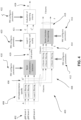
- a process 200 is shown for aperiodic SRS scheduling offset selection.
- the process includes determining the usage type of the SRS. If the SRS is determined at 202 to be of the non-codebook transmission type, then, at operation 204, the process includes determining whether an associated CSI-RS has been configured for the SRS. If yes, then, at operation 206, the process includes selecting a larger scheduling offset for the aperiodic SRS, and if no, then, at operation 208, the process includes selecting a smaller scheduling offset for the aperiodic SRS.
- the process includes determining whether a spatial relationship information has been configured for the SRS. If yes, then, at operation 212, the process includes selecting a smaller scheduling offset for the aperiodic SRS, and if no, then, at operation 214, the process includes selecting a larger scheduling offset for the aperiodic SRS.
- the spatial domain transmission filter (TX beam) for PUSCH may be the same as that corresponding to the indicated SRS resource, regardless of whether the SRS is actually transmitted or not.
- UE may use TX beam 1 to transmit PUSCH.
- the indicated Synchronization Signal Block (SSB)/CSI-RS/SRS may be associated with one instance of a SSB/CSI-RS/SRS signal, for example according to any of the options to be described below and in relation to Fig. 3 .
- Signaling diagram 300 includes uplink transmissions from a UE to a gNodeB, including transmissions 302, 306, 310, 312, 314, and 316, and downlink transmissions from the gNodeB to the UE, including transmissions 304.
- Transmission 302 from the UE includes a SRS transmission on SRS resource 0 using Tx beam 0.
- the UE receives from the gNodeB and decodes a transmission 304 on resource 1 including a beam indication, for example by way of a medium access control (MAC) control element (CE), for PUCCH, based on a SRI indication of 0.
- MAC medium access control
- CE medium access control element
- the transmission 304 may include one or more indicated SRS for subsequent Tx beams to be used by the UE for uplink transmission of PUCCH in successive PUCCH instances.
- transmission 306 from the UE includes a SRS transmission on SRS resource 0 using Tx beam 1.
- the UE applies parameters from the MAC CE in transmission 304.
- transmission 310 from the UE includes a SRS transmission on SRS resource 0 using Tx beam 2, and then, at transmission 312, the UE transmits a PUCCH on resource 0 at an instance 0.
- Transmission 312 is followed by transmission 314 from the UE which includes a SRS transmission on SRS resource 0 using Tx beam 3.
- the UE transmits a PUCCH on resource 0 at an instance 1.
- Table 318 in Fig. 3 helps to show various Tx beam indexes for each of PUCCH instance 0 at transmission 312 and PUCCH instance 1 at transmission 316.
- the PUCCH transmissions 312 and 316 in diagram 300 may be transmitted based on respective Tx beam indexes based on up to four options as will be described further below, and as set forth in Table 318.
- the UE may not change the spatial domain filter for each instance of SRS for beam management and/or SSB/CSI-RS with the same ID.
- the UE may expect the PT-RS port index is to be configured for SRS with usage configured to be non-codebook, or the UE may expect the PT-RS port index is to be configured for indicated SRS resource(s) in a set with usage configured to be non-codebook.
- the UE may not transmit PT-RS.
- the UE may assume the PT-RS port index is based on a default value, such as a default value of 0.
- the UE may assume only a single PT-RS port is transmitted when PT-RS is configured.
- a UE may report the maximum number of SRS resource sets for beam management it may support for each time domain behavior as a UE capability, where the time domain behavior indicates whether the SRS is aperiodic, semi-persistent or periodic.
- the UE capability may be reported as follows:
- an ID for simultaneous transmission e.g. antenna port(s) group ID
- an ID for simultaneous transmission may be indicated according to one embodiment.
- those SRS resources may be transmitted simultaneously; otherwise, the SRS with highest priority may be transmitted and the other SRS may be dropped, and the priority may be based on the time domain behavior, for example with the order of priority decreasing from aperiodic SRS to semi-persistent SRS and finally to periodic SRS.
- SRS resources from different SRS resource sets configured with different usage e.g. codebook, non-codebook, antenna switching or beam management
- codebook e.g. codebook, non-codebook, antenna switching or beam management
- only the SRS resources from different SRS resource sets configured with the same usage may be simultaneously transmitted.
- the SRS with the highest priority may be transmitted and the other SRS may be dropped.
- the dropping rule could be that a priority decreases from beam management to codebook to non-codebook to antenna switching SRS transmissions.
- the dropping rule may be based on component carrier (CC) index and/or SRS usage and/or time domain behavior for SRS.
- Beam management refers to a set of layer 1/layer 2 (L1/L2) procedures to acquire and maintain a set of transmission/reception point(s) (TRP or TRxP to be used interchangeably) and/or UE beams that may be used for downlink (DL) and uplink (UL) transmission/reception.
- the TRP may be used herein to refer to a device with an antenna array (with one or more antenna elements) available to the network and located at a specific geographical location.
- the TRP may include a gNodeB.
- Beam determination refers to TRP(s) or to the UE's ability to select its own Tx/Rx beam(s).
- Beam measurement refers to TRP or to the UE ability to measure characteristics of received beamformed signals.
- Beam reporting refers the UE's ability to report information of beamformed signal(s) based on beam measurement.
- Beam sweeping refers to operation(s) involving covering a spatial area with beams transmitted and/or received during a time interval in a predetermined manner.
- Tx/Rx beam correspondence at a TRP holds if at least one of the following conditions are satisfied: TRP is able to determine a TRP Rx beam for the uplink reception based on the UE's downlink measurement on TRP's one or more Tx beams; and TRP is able to determine a TRP Tx beam for the downlink transmission based on TRP's uplink measurement on TRP's one or more Rx beams.
- Tx/Rx beam correspondence at a UE holds if at least one of the following is satisfied: the UE is able to determine a UE Tx beam for the uplink transmission based on the UE's downlink measurement on UE's one or more Rx beams; the UE is able to determine a UE Rx beam for the downlink reception based on TRP's indication based on uplink measurement on UE's one or more Tx beams; and Capability indication of the UE beam correspondence related information to TRP is supported.
- DL beam management may include procedures P-1, P-2, and P-3.
- a procedure P-1 may be used to enable UE measurement on different TRP Tx beams to support selection of TRP Tx beams/UE Rx beam(s).
- procedure P-1 typically includes a intra/inter-TRP Tx beam sweep from a set of different beams.
- procedure P-1 typically includes a UE Rx beam sweep from a set of different beams.
- Procedure P-2 may be used to enable UE measurement on different TRP Tx beams to possibly change inter/intra-TRP Tx beam(s).
- Procedure P-2 may be a special case of procedure P-1 wherein procedure P-2 is used for a possibly smaller set of beams for beam refinement than procedure P-1.
- Procedure P-3 may be used to enable UE measurement on the same TRP Tx beam to change the UE Rx beam in the case UE uses beamforming.
- Procedures P-1, P-2, and P-3 may be used for aperiodic beam reporting.
- UE measurements based on reference signals (RS) for beam management may include K beams (where K is a total number of configured beams), and the UE may report measurement results of N selected Tx beams from a gNodeB (where N may or may not be a fixed number).
- RS reference signals
- Beam information that is to be reported may include measurement quantities for the N beam(s) and information indicating N DL Tx beam(s), if N ⁇ K. Other information or data may be included in or with the beam information.
- NZP non-zero power
- a UE may report N' CSI-RS Resource Indicator (CRIs).
- the UE may trigger a mechanism to recover from beam failure, which procedure is referred to a "beam recovery”, "beam failure recovery request procedure", and/or the like.
- a beam failure event may occur when the quality of beam pair link(s) of an associated control channel falls below a threshold, when a time-out of an associated timer occurs, or the like.
- the beam recovery mechanism is triggered when beam failure occurs.
- the network may explicitly configure the UE with resources for UL transmission of signals for recovery purposes. Configurations of resources are supported where the base station (e.g., a TRP or gNodeB, or the like) is listening from all or partial directions (e.g., a random access region).
- the UL transmission/resources to report beam failure may be located in the same time instance as a Physical Random Access Channel (PRACH) or resources orthogonal to PRACH resources, or at a time instance (configurable for a UE) different from PRACH.
- Transmission of DL a signal may be supported for allowing the UE to monitor the beams for identifying new potential beams.
- a beam failure may be declared if one, multiple, or all serving PDCCH beams fail.
- the beam failure recovery request procedure may be initiated when a beam failure is declared.
- the beam failure recovery request procedure may be used for indicating to a serving gNodeB (or TRP) of a new SSB or CSI-RS when beam failure is detected on a serving SSB(s)/CSI-RS(s).
- a beam failure may be detected by the lower layers and indicated to a Media Access Control (MAC) entity of the UE.
- MAC Media Access Control
- Beam management also includes providing or not providing beam-related indications.
- beam-related indication information pertaining to a UE-side beamforming/receiving procedure used for CSI-RS-based measurement may be indicated through Quasi Co-Location to the UE.
- the same or different beams on the control channel and the corresponding data channel transmissions may be supported.
- DL beam indications may be based on one or more Transmission Configuration Indication (TCI) state(s).
- TCI state(s) are indicated in a TCI list that is configured by a radio resource control (RRC) and/or Media Access Control (MAC) Control Element (CE).
- RRC radio resource control
- MAC Media Access Control
- the UE may be configured with a list of up to M TCI-State configurations within the higher layer parameter PDSCH-Config to decode PDSCH according to a detected PDCCH with DCI intended for the UE and the given serving cell, where M depends on the UE capability.
- Each TCI-State contains parameters for configuring a quasi co-location relationship between one or two downlink reference signals and the DM-RS ports of the PDSCH.
- the quasi co-location relationship is configured by the higher layer parameter qcl-Type1 for the first DL RS, and qcl-Type2 for the second DL RS (if s second DL RS is configured).
- the quasi co-location types corresponding to each DL RS is given by the higher layer parameter qcl-Type in QCL-Info and may take one of the following values: QCL-TypeA: ⁇ Doppler shift, Doppler spread, average delay, delay spread); QCL-TypeB: ⁇ Doppler shift, Doppler spread ⁇ ; QCL-TypeC: ⁇ average delay, Doppler shift ⁇ ; QCL-TypeD: ⁇ Spatial Rx parameter ⁇ .
- the UE receives an activation command used to map up to 8 TCI states to the codepoints of the DCI field 'Transmission Configuration Indication'.
- the indicated mapping between TCI states and codepoints of the DCI field 'Transmission Configuration Indication' may be applied starting from slot n + 3 N slot subframe , ⁇ + 1 .
- the UE may assume that the DM-RS ports of PDSCH of a serving cell are quasi co-located with the Synchronization Signal/Physical Broadcast Channel (SS/PBCH) block determined in the initial access procedure with respect to 'QCL-TypeA', and when applicable, also with respect to'QCL-TypeD'.
- SS/PBCH Synchronization Signal/Physical Broadcast Channel
- the UE may assume that the TCI field is present in the DCI format 1_1 of the PDCCH transmitted on the CORESET. If tci-PresentInDCI is not configured for the CORESET scheduling the PDSCH or the PDSCH is scheduled by a DCI format 1_0, for determining PDSCH antenna port quasi co-location, the UE may assume that the TCI state for the PDSCH is identical to the TCI state applied for the CORESET used for the PDCCH transmission.
- CORESET control resource set
- the UE may use the TCI-State according to the value of the 'Transmission Configuration Indication' field in the detected PDCCH with DCI for determining PDSCH antenna port quasi co-location.
- the UE may assume that the DM-RS ports of PDSCH of a serving cell are quasi co-located with the RS(s) in the TCI state with respect to the QCL type parameter(s) given by the indicated TCI state if the time offset between the reception of the DL DCI and the corresponding PDSCH is equal to or greater than a threshold Threshold-Sched-Offset, where the threshold is based on reported UE capability.
- the UE may assume that the DM-RS ports of PDSCH of a serving cell are quasi co-located with the RS(s) in the TCI state with respect to the QCL parameter(s) used for the PDCCH quasi co-location indication of the lowest CORESET-ID in the latest slot in which one or more CORESETs within the active BWP of the serving cell are configured for the UE. If none of the configured TCI states contains 'QCL-TypeD', the UE may obtain the other QCL assumptions from the indicated TCI states for its scheduled PDSCH irrespective of the time offset between the reception of the DL DCI and the corresponding PDSCH.
- the UE may expect that a TCI-State indicates one of the following quasi-colocation type(s):
- the UE may expect that a TCI-State indicates one of the following quasi co-location type(s):
- the UE may expect that a TCI-State indicates one of the following quasi co-location type(s):
- the UE may expect that a Tel-State indicates one of the following quasi co-location type(s):
- the UE may expect that a TCI-State indicates one of the following quasi co-location type(s):
- a beam failure recovery request could be delivered over dedicated PRACH or PUCCH resources.
- a UE may be configured, for a serving cell, with a set q ⁇ 0 of periodic CSI-RS resource configuration indexes by higher layer parameter Beam-Failure-Detection-RS-ResourceConfig and with a set q ⁇ 1 of CSI-RS resource configuration indexes and/or SS/PBCH block indexes by higher layer parameter candidate-Beam-RS-List for radio link quality measurements on the serving cell.
- the beam failure detection could be based on CSI-RS or SSB, which is spatially Quasi Co-Located (QCLed) with the PDCCH Demodulation Reference Signal (DMRS).
- DMRS Demodulation Reference Signal
- the UE determines q ⁇ 0 to include SS/PBCH blocks and periodic CSI-RS configurations with same values for higher layer parameter TCI-StatesPDCCH as for control resource sets (CORESET) that the UE is configured for monitoring PDCCH.
- CORESET control resource sets
- the physical layer of a UE may assess the radio link quality according to a set q ⁇ 0 of resource configurations against a threshold Qout,LR.
- the threshold Qout,LR may corresponds to a default value of higher layer parameter RLM-IS-OOS-thresholdConfig and Beam-failure-candidate-beam-threshold, respectively.
- the UE may assess the radio link quality only according to periodic CSI-RS resource configurations or SS/PBCH blocks that are quasi co-located, with the DM-RS of PDCCH receptions monitored by the UE.
- the UE may apply the configured Qin,LR threshold for the periodic CSI-RS resource configurations.
- the UE may apply the Qout,LR threshold for SS/PBCH blocks after scaling a SS/PBCH block transmission power with a value provided by a higher layer parameter Pc_SS.
- the MAC entity may start a beam failure recovery timer (beamFailureRecoveryTimer) and may initiate a Random Access procedure. If the beamFailureRecoveryTimer expires, then the MAC entity may indicate a beam failure recovery request failure to upper layers. If a DL assignment or UL grant has been received (e.g., on a PDCCH addressed for a cell radio network temporary identifier (C-RNTI)), then the MAC entity may stop and reset beamFailureRecoveryTimer and consider the beam failure recovery request procedure to be successfully completed.
- beamFailureRecoveryTimer e.g., a DL assignment or UL grant has been received (e.g., on a PDCCH addressed for a cell radio network temporary identifier (C-RNTI)
- the UE in the RRC_CONNECTED mode is to measure one or multiple beams of a cell, and the measurement results (e.g., power values) are averaged to derive the cell quality.
- the UE derives cell measurement results by measuring one or multiple beams associated per cell as configured by the network. For all cell measurement results in RRC_CONNECTED mode, the UE may apply layer 3 filtering before using the measured results for evaluation of reporting criteria and measurement reporting.
- the network may configure Reference Signal Received Power (RSRP), Reference Signal Received Quality (RSRQ), and/or Signal to Interference and Noise Ratio (SINR) as a trigger quantity.
- Reporting quantities may be the same as the trigger quantity or combinations of quantities (e.g., RSRP and RSRQ; RSRP and SINR; RSRQand SINR; RSRP, RSRQand SINR).
- the network may also configure the UE to report measurement information per beam, which may either be measurement results per beam with respective beam identifier(s) or only beam identifier(s)). If beam measurement information is configured to be included in measurement reports, the UE may apply the layer 3 beam filtering. However, the exact layer 1 filtering of beam measurements used to derive cell measurement results is implementation dependent.
- the UE may be configured to consider a subset of the detected beams, such as the N best beams above an absolute threshold. Filtering may take place at two different levels include at the physical layer (PHY) to derive beam quality and then at the RRC level to derive cell quality from multiple beams. Cell quality from beam measurements may be derived in the same way for the serving cell(s) and for the non-serving cell(s).
- PHY physical layer
- RRC Radio Resource Control
- Measurement reports may contain the measurement results of the X best beams if the UE is configured to do so by the gNodeB.
- the UE may be configured to measure CSI-RS resources and estimate a downlink channel state based on the CSI-RS measurements.
- the UE may feed the estimated channel state back to the gNodeB to be used in link adaptation.
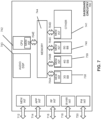
- FIG. 4 is a schematic illustration of a measurement model flow for measurement reports by the UE to the gNodeB.
- point A at 402 includes measurements (e.g., beam specific samples) internal to the PHY for beams from the gNodeB.
- Layer 1 (L1) filtering at 404 includes internal layer 1 filtering circuitry for filtering the inputs measured at point A 402. The exact filtering mechanisms and how the measurements are actually executed at the PHY may be implementation specific.
- the measurements (e.g., beam specific measurements) are reported by the L1 filtering to layer 3 (L3) beam filtering circuitry and the beam consolidation/selection circuitry at point A1406.
- the configuration of the beam may be provided by RRC signaling.
- a measurement (e.g., cell quality) derived from the beam-specific measurements may then be reported at point B 410 to L3 filtering for cell quality circuitry at 420 after beam consolidation/selection.
- the reporting period at point B 410 may be equal to one measurement period at point A1.
- the L3 filtering for cell quality circuitry 420 may be configured to filter the measurements provided at point B 419.
- the configuration of the Layer 3 filters at 420 may be provided by the aforementioned RRC signaling or different/separate RRC signaling.
- the filtering reporting period at point C 421 may be equal to one measurement period at point B 419.
- a measurement after processing in the layer 3 filter circuitry may be provided to the evaluation of reporting criteria circuitry 422 at point C 421.
- the reporting rate may be identical to the reporting rate at point B 419. This measurement input may be used for one or more evaluation of reporting criteria at point C 421.
- Evaluation of reporting criteria circuitry 422 is configured to check whether actual measurement reporting is necessary at point D 424 .
- the evaluation may be based on more than one flow of measurements at reference point C 421. In one example, the evaluation may involve a comparison between different measurements, such as a measurement provided at point C and another measurement provided at point C1 also at 421.
- the UE may evaluate the reporting criteria at least every time a new measurement result is reported at point C, C1421.
- the reporting criteria configuration is provided by the aforementioned RRC signaling (UE measurements) or different/separate RRC signaling.
- measurement report information (e.g., as a message) may sent on the radio interface at point D.
- measurements provided at point A1 406 are provided in the form of K beams 408 to L3 Beam filtering circuitry 412, which is configured to perform beam filtering of the provided measurements (e.g., beam specific measurements).
- the configuration of the beam filters may be provided by the aforementioned RRC signaling or different/separate RRC signaling.
- the filtering reporting period at point E 414 may be equal to one measurement period at A1 406.
- the K beams 408 may correspond to the measurements on New Radio (NR)-synchronization signal (SS) block (SSB) or Channel State Information Reference Signal (CSI-RS) resources configured for L3 mobility by a gNodeB and detected by the UE at L1.
- NR New Radio
- SS SS-synchronization signal
- CSI-RS Channel State Information Reference Signal
- a measurement is provided to beam selection for reporting circuitry at point E 414.
- This measurement is used as an input for selecting the X measurements to be reported.
- the reporting rate may be identical to the reporting rate at point A1 406.
- the beam selection for beam reporting circuitry 416 may be configured to select the X measurements from the measurements provided at point E 414.
- the configuration of this module may be provided by the aforementioned RRC signaling or different/separate RRC signaling.
- the beam measurement information to be included in a measurement report is sent or scheduled for transmission on the radio interface at point F 418.
- L1 filtering introduces a certain level of measurement averaging. Exactly how and when the UE performs the required measurements is implementation specific to the point that the output at B 419 fulfils the predefined performance requirements. L3 filtering for cell quality and related parameters do not introduce any delay in the sample availability between B 419 and C 421. Measurement at point C, C1421 is the input used in the event evaluation. L3 Beam filtering and related parameters do not introduce any delay in the sample availability between E 414 and F 418.
- the measurement reports may include a measurement identity of an associated measurement configuration that triggered the reporting.
- Cell and beam measurement quantities to be included in measurement reports may be configured by the network (e.g., using RRC signaling); the number of non-serving cells to be reported may be limited through configuration by the network; cells belonging to a blacklist configured by the network may not be used in event evaluation and reporting, and conversely when a whitelist is configured by the network, only the cells belonging to the whitelist may be used in event evaluation and reporting (by contrast), when a whitelist is configured by the network, only the cells belonging to the whitelist may be used in event evaluation and reporting; and beam measurements to be included in measurement reports may be configured by the network (beam identifier only, measurement result and beam identifier, or no beam reporting).
- Intra-frequency neighbor (cell) measurements include SSB based intra-frequency measurement(s) and CSI-RS based intra-frequency measurements.
- SSB based intra-frequency measurements is/are defined as an SSB based intra-frequency measurement provided the center frequency of the SSB of the serving cell and the center frequency of the SSB of the neighbor cell are the same, and the subcarrier spacing of the two SSBs is also the same.
- CSI-RS based intra-frequency measurements is/are defined as a CSI-RS based intra-frequency measurement provided the bandwidth of the CSI-RS resource on the neighbor cell configured for measurement is within the bandwidth of the CSI-RS resource on the serving cell configured for measurement, and the subcarrier spacing of the two CSI-RS resources is the same.
- Inter-frequency neighbor (cell) measurements include SSB based inter-frequency measurement(s) and CSI-RS based inter-frequency measurements.
- SSB based inter-frequency measurements is/are defined as an SSB based inter-frequency measurement provided the center frequency of the SSB of the serving cell and the center frequency of the SSB of the neighbor cell are different, or the subcarrier spacing of the two SSBs is different.
- one measurement object corresponds to one SSB and the UE considers different SSBs as different cells.
- CSI-RS based inter-frequency measurements are defined as a CSI-RS based inter-frequency measurement provided the bandwidth of the CSI-RS resource on the neighbor cell configured for measurement is not within the bandwidth of the CSI-RS resource on the serving cell configured for measurement, or provided the subcarrier spacing of the two CSI-RS resources is different.
- Whether a measurement is non-gap-assisted or gap-assisted depends on the capability of the UE, the active BWP of the UE and the current operating frequency. In non-gap-assisted scenarios, the UE may carry out such measurements without measurement gaps. In gap-assisted scenarios, the UE may not be assumed to be able to carry out such measurements without measurement gaps.
- the UE may be configured with one or more Sounding Reference Symbol (SRS) resource sets as configured by the higher layer parameter SRS-ResourceSet.
- SRS Sounding Reference Symbol
- the UE may be configured with K ⁇ 1 SRS resources (higher later parameter SRS-Resource), where the maximum value of K is indicated by [SRS_capability].
- the SRS resource set applicability may be configured by the higher layer parameter SRS-SetUse.
- the higher layer parameter SRS-SetUse is set to 'BeamManagement', only one SRS resource in each of multiple SRS sets may be transmitted at a given time instant.
- the SRS resources in different SRS resource sets may be transmitted simultaneously.
- At least one state of the DCI field is used to select at least one out of the configured SRS resource set.
- the following SRS parameters may be semi-statically configurable by higher layer parameter SRS-Resource.
- the UE may be configured by the higher layer parameter resourceMapping in SRS-Resource with an SRS resource occupying a location within the last 6 symbols of the slot.
- the UE may be configured to transmit SRS after the transmission of the PUSCH and the corresponding DM-RS.
- the semi-persistent SRS configuration may be considered to be active in the UL BWP which is active when SRS resource configuration is activated, otherwise it may be considered suspended.
- the 2-bit SRS request field in DCI format 0_1, 1_1 indicates the triggered SRS resource set.
- the 2-bit SRS request field in DCI format 2_3 indicates the triggered SRS resource set.
- the UE is to not transmit SRS when semi-persistent and periodic SRS are configured in the same symbol(s) with PUCCH carrying only CSI report(s), or only L1-RSRP report(s) or if aperiodic SRS is configured and PUCCH consists of beam failure request.
- the UE is to not transmit SRS when semi-persistent or periodic SRS is configured or aperiodic SRS is triggered to be transmitted in the same symbol(s) with PUCCH carrying HARQ-ACK and/or SR. In the case that SRS is not transmitted due to overlap with PUCCH, only the SRS symbol(s) that overlap with PUCCH symbol(s) are dropped.
- PUCCH is to not be transmitted when aperiodic SRS is triggered to be transmitted to overlap in the same symbol with semi-persistent or periodic PUCCH carrying semi-persistent/periodic CSI report(s) or semi-persistent/periodic L1-RSRP report(s) only.
- the UE is not expected to be configured with aperiodic SRS and PUCCH formats 0 or 2 with aperiodic CSI report in the same symbol.
- the UE In case of intra-band carrier aggregation, the UE is not expected to be configured with SRS and PUSCH/UL DM-RS/UL PT-RS/PUCCH formats 1, 3 or 4 in the same symbol.
- the UE is to not transmit simultaneously SRS resource(s) and PRACH.
- the UE When the UE is configured with the higher layer parameter usage in SRS-ResourceSet set to 'antennaSwitching,' and a guard period of Y symbols is configured according to Subclause 6.2.1.2, the UE is to use the same priority rules as defined above during the guard period as if SRS was configured.
- the UE may be configured to transmit an SRS resource on N s ⁇ ⁇ 1,2,4 ⁇ adjacent symbols within the last six symbols of a slot, where all antenna ports of the SRS resource are mapped to each symbol of the resource.
- the UE is configured with repetition factor R ⁇ 1,2,4 ⁇ by higher layer parameter resourceMapping in SRS-Resource where R ⁇ Ns.
- all antenna ports of the SRS resource in each slot are mapped in each of the N s symbols to the same set of subcarriers in the same set of PRBs.
- All antenna ports of the SRS resource are mapped to the same set of subcarriers within each pair of R adjacent OFDM symbols of the resource in each slot.
- the UE may be configured with a guard period of Y symbols, in which the UE does not transmit any other signal, in the case the SRS resources of a set are transmitted in the same slot.
- the guard period may be in-between the SRS resources of the set.
- the UE is to expect to be configured with the same number of SRS ports, either one or two, for all SRS resources in the SRS resource set(s).
- the UE For a carrier of a serving cell with slot formats comprised of DL and UL symbols not configured for PUSCH/PUCCH transmission the UE is to not transmit SRS whenever SRS transmission (including any interruption due to uplink or downlink RF retuning time as defined by higher layer parameters rf-RetuningTimeUL and rf-RetuningTimeDL) on the carrier of the serving cell and PUSCH/PUCCH transmission carrying HARQ-ACK/positive SR/RI/CRI and/or PRACH happen to overlap in the same symbol and that may result in uplink transmissions beyond the UE's indicated uplink carrier aggregation capability included in the SRS_capability.
- SRS transmission including any interruption due to uplink or downlink RF retuning time as defined by higher layer parameters rf-RetuningTimeUL and rf-RetuningTimeDL
- the UE For a carrier of a serving cell with slot formats comprised of DL and UL symbols, not configured for PUSCH/PUCCH transmission, the UE is to not transmit a periodic/semi-persistent type 0 SRS whenever periodic/semi-persistent SRS transmission (including any interruption due to uplink or downlink RF retuning time as defined by higher layer parameters rf-RetuningTimeUL and rf-RetuningTimeDL) on the carrier of the serving cell and PUSCH transmission carrying aperiodic CSI happen to overlap in the same symbol and that may result in uplink transmissions beyond the UE's indicated uplink carrier aggregation capability included in the SRS_capability.
- a periodic/semi-persistent type 0 SRS whenever periodic/semi-persistent SRS transmission (including any interruption due to uplink or downlink RF retuning time as defined by higher layer parameters rf-RetuningTimeUL and rf
- the UE For a carrier of a serving cell with slot formats comprised of DL and UL symbols, not configured for PUSCH/PUCCH transmission, the UE is to drop PUCCH/PUSCH transmission carrying periodic CSI comprising only Channel Quality Indicator (CQI)/Precoding Matrix Indicator (PMI), and/or SRS transmission on another serving cell configured for PUSCH/PUCCH transmission whenever the transmission and SRS transmission (including any interruption due to uplink or downlink RF retuning time as defined by higher layer parameters rf-RetuningTimeUL and rf-RetuningTimeDL) on the serving cell happen to overlap in the same symbol and that may result in uplink transmissions beyond the UE's indicated uplink carrier aggregation capability included in the SRS_capability.
- CQI Channel Quality Indicator
- PMI Precoding Matrix Indicator
- the UE For a carrier of a serving cell with slot formats comprised of DL and UL symbols not configured for PUSCH/PUCCH transmission, the UE is to drop PUSCH transmission carrying aperiodic CSI comprising only CQI/PMI whenever the transmission and aperiodic SRS transmission (including any interruption due to uplink or downlink RF retuning time) as defined by higher layer parameters rf-RetuningTimeUL and rf-RetuningTimeDL) on the carrier of the serving cell happen to overlap in the same symbol and that may result in uplink transmissions beyond the UE's indicated uplink carrier aggregation capability included in the SRS_capability.
- aperiodic CSI comprising only CQI/PMI whenever the transmission and aperiodic SRS transmission (including any interruption due to uplink or downlink RF retuning time) as defined by higher layer parameters rf-RetuningTimeUL and rf-RetuningTimeDL) on the carrier of the serving
- the order of the triggered SRS transmission on the serving cells follow the order of the serving cells in the indicated set of serving cells configured by higher layers, where the UE in each serving cell transmits the configured one or two SRS resource set(s) with higher layer parameter SRS-SetUse set to 'antenna switching' and higher layer parameter resourceType in SRS-ResourceSet set to 'aperiodic'.
- the order of the triggered SRS transmission on the serving cells follow the order of the serving cells with aperiodic SRS triggered in the DCI, and the UE in each serving cell transmits the configured one or two SRS resource set(s) with higher layer parameter SRS-SetUse set to 'antenna switching' and higher layer parameter resourceType in SRS-ResourceSet set to 'aperiodic'.
- the UE may be configured with SRS resource(s) on a carrier c1 with slot formats comprised of DL and UL symbols and not configured for PUSCH/PUCCH transmission.
- the UE is configured with higher layer parameter srs-SwitchFromServCelllndex and srs-SwitchFromCarrier the switching from carrier c2 which is configured for PUSCH/PUCCH transmission.
- the UE temporarily suspends the uplink transmission on carrier c2.
- the UE is not configured for PUSCH/PUCCH transmission on carrier c1 with slot formats comprised of DL and UL symbols, and if the UE is not capable of simultaneous reception and transmission on carrier c1 and serving cell c2, the UE is not expected to be configured or indicated with SRS resource(s) such that SRS transmission on carrier c1 (including any interruption due to uplink or downlink RF retuning time as defined by higher layer parameters rf-RetuningTimeUL and rf-RetuningTimeDL) would collide with the REs corresponding to the SS/PBCH blocks configured for the UE or the slots belonging to a control resource set indicated by [SystemInformationBlockType0] or [SystemInformationBlockType1] on serving cell c2.
- n-th (n ⁇ 1) aperiodic SRS transmission on a cell c
- the UE upon detection of a positive SRS request on a grant, the UE is to commence this SRS transmission on the configured symbol and slot provided
- the UE may simultaneously transmit SRS and PUCCH/PUSCH across component carriers in different bands subject to the UE's capability.
- the UE may simultaneously transmit PRACH and SRS/PUCCH/PUSCH across component carriers in different bands subject to UE's capability.
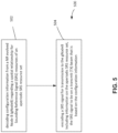
- a process 500 includes at operation 502, encoding a SRS signal for transmission to the gNodeB including information on the aperiodic SRS resource set, the SRS signal to be on a transmit (TX) beam that is based on the configuration information; and at operation 504, encoding a SRS signal for transmission to the gNodeB including information on the aperiodic SRS resource set, the SRS signal to be on a transmit (TX) beam that is based on the configuration information.
- Fig. 6 illustrates an architecture of a system 600 of a network according to some embodiments.
- the system 600 is shown to include a user equipment (UE) 601 and a UE 602.
- the UEs 601 and 602 are illustrated as smartphones (e.g., handheld touchscreen mobile computing devices connectable to one or more cellular networks) but may also comprise any mobile or non-mobile computing device.
- the UEs 601 and 602 may be configured to connect, e.g., communicatively couple, with a radio access network (RAN) 610.
- RAN radio access network
- the UEs 601 and 602 utilize connections 603 and 604, respectively, each of which comprises a physical communications interface or layer (discussed in further detail below); in this example, the connections 603 and 604 are illustrated as an air interface to enable communicative coupling and may be consistent with cellular communications protocols.
- the UEs 601 and 602 may further directly exchange communication data via a ProSe interface 605.
- the ProSe interface 605 may alternatively be referred to as a sidelink interface comprising one or more logical channels, including but not limited to a Physical Sidelink Control Channel (PSCCH), a Physical Sidelink Shared Channel (PSSCH), a Physical Sidelink Discovery Channel (PSDCH), and a Physical Sidelink Broadcast Channel (PSBCH).
- PSCCH Physical Sidelink Control Channel
- PSSCH Physical Sidelink Shared Channel
- PSDCH Physical Sidelink Discovery Channel
- PSBCH Physical Sidelink Broadcast Channel
- the UE 602 is shown to be configured to access an access point (AP) 606 via connection 607.
- the connection 607 may comprise a local wireless connection, such as a connection consistent with any IEEE 802.11 protocol, wherein the AP 606 would comprise a wireless fidelity (WiFi ® ) router.
- WiFi ® wireless fidelity
- the AP 606 is shown to be connected to the Internet without connecting to the core network of the wireless system (described in further detail below).
- the RAN 610 may include one or more access nodes that enable the connections 603 and 604. These access nodes (ANs) may be referred to as base stations (BSs), NodeBs, evolved NodeBs (eNBs), next Generation or New Radio evolved NodeBs (gNodeB), RAN nodes, and so forth, and may comprise ground stations (e.g., terrestrial access points) or satellite stations providing coverage within a geographic area (e.g., a cell).
- BSs base stations
- NodeBs evolved NodeBs
- gNodeB next Generation or New Radio evolved NodeBs
- RAN nodes and so forth, and may comprise ground stations (e.g., terrestrial access points) or satellite stations providing coverage within a geographic area (e.g., a cell).
- the RAN 610 may include one or more RAN nodes for providing macrocells, e.g., macro RAN node 611, and one or more RAN nodes for providing femtocells or picocells (e.g., cells having smaller coverage areas, smaller user capacity, or higher bandwidth compared to macrocells), e.g., low power (LP) RAN node 612.
- macro RAN node 611 e.g., macro RAN node 611
- femtocells or picocells e.g., cells having smaller coverage areas, smaller user capacity, or higher bandwidth compared to macrocells
- LP low power
- the UEs 601 and 602 may be configured to communicate using Orthogonal Frequency-Division Multiplexing (OFDM) communication signals with each other or with any of the RAN nodes 611 and 612 over a multicarrier communication channel in accordance various communication techniques, such as, but not limited to, an Orthogonal Frequency-Division Multiple Access (OFDMA) communication technique (e.g., for downlink communications) or a Single Carrier Frequency Division Multiple Access (SC-FDMA) communication technique (e.g., for uplink and ProSe or sidelink communications), although the scope of the embodiments is not limited in this respect.
- OFDM signals may comprise a plurality of orthogonal subcarriers.
- the RAN 610 is shown to be communicatively coupled to a core network (CN) 620 - via an S1 interface 613.
- the CN 620 may be an evolved packet core (EPC) network, a NextGen Packet Core (NPC) network, or some other type of CN.
- EPC evolved packet core
- NPC NextGen Packet Core
- the S1 interface 613 is split into two parts: the S1-U interface 614, which carries traffic data between the RAN nodes 611 and 612 and the serving gateway (S-GW) 622, and the S1-mobility management entity (MME) interface 615, which is a signalling interface between the RAN nodes 611 and 612 and MMEs 621.
- S-GW serving gateway
- MME S1-mobility management entity
- the CN 620 includes network elements.
- the term "network element” may describe a physical or virtualized equipment used to provide wired or wireless communication network services.
- the CN 620 comprises, as network elements, the MMEs 621, the S-GW 622, the Packet Data Network (PDN) Gateway (P-GW) 623, and a home subscriber server (HSS) 624.
- the MMEs 621 may be similar in function to the control plane of legacy Serving General Packet Radio Service (GPRS) Support Nodes (SGSN).
- GPRS General Packet Radio Service
- Fig. 6 such as the UEs and gNodeB's of Fig. 6 , may be used in any of the embodiments described herein.
- Fig. 7 illustrates example interfaces of baseband circuitry according to various embodiments.
- the baseband circuitry 700 may be included in a UE or gNodeB, for example, in UE or gNodeB of Fig. 6 , and may comprise processors 738-742 and a memory 744 utilized by said processors.
- Each of the processors 738-732 may include a memory interface, 704A-704E, respectively, to send/receive data to/from the memory 744.
- Baseband circuitry 700 may also include an audio digital signal processor (Audio DSP) 743.
- Audio DSP audio digital signal processor
- the baseband circuitry 700 may further include one or more interfaces to communicatively couple to other circuitries/devices, such as a memory interface 712 (e.g., an interface to send/receive data to/from memory external to the baseband circuitry 700), an application circuitry interface 714 (e.g., an interface to send/receive data to/from an application circuitry), an RF circuitry interface 716 (e.g., an interface to send/receive data to/from an RF circuitry), a wireless hardware connectivity interface 718 (e.g., an interface to send/receive data to/from Near Field Communication (NFC) components, Bluetooth ® components (e.g., Bluetooth ® Low Energy), Wi-Fi ® components, and other communication components), and a power management interface 720 (e.g., an interface to send/receive power or control signals to/from a power management integrated circuit (PMIC).
- a memory interface 712 e.g., an interface to send/receive data to/
Landscapes
- Engineering & Computer Science (AREA)
- Signal Processing (AREA)
- Computer Networks & Wireless Communication (AREA)
- Mobile Radio Communication Systems (AREA)
Claims (12)
- Vorrichtung einer New Radio-, NR-, Benutzerausrüstung, UE, (601), wobei die Vorrichtung eine Hochfrequenz-, HF-, Schnittstelle (716) und eine Verarbeitungsschaltung (742) beinhaltet, die mit der HF-Schnittstelle (716) gekoppelt ist, wobei die Verarbeitungsschaltung (742) dazu konfiguriert ist:Konfigurationsinformationen von einem NR evolved Node B, gNodeB, bezüglich einer räumlichen Beziehung für Sondierungsreferenzsignal-, SRS-, Ressourcen eines aperiodischen SRS-Ressourcensatzes zu decodieren; undein SRS-Signal für die Übertragung zum gNodeB, das Informationen über den aperiodischen SRS-Ressourcensatz beinhaltet, zu codieren, wobei sich das SRS-Signal auf einem Übertragungs-, TX-, Strahl befinden soll, der auf den Konfigurationsinformationen basiert,wobei der aperiodische SRS-Ressourcensatz einer nichtcodebuchbasierten Übertragung dient, und ein minimaler Planungsversatz zwischen einem letzten Symbol von Planungs-Downlink-Steuerinformationen, DCI, und einem ersten Symbol des SRS-Signals gleich einem Planungsversatz M2 ist, wenn ein Kanalzustandsinformation-, CSI-, Referenzsignal, CSI-RS, für die UE konfiguriert ist, und gleich einem Planungsversatz M1 ist, wenn die CSI-RS nicht für die UE konfiguriert ist, wobei M2 größer als M1 ist.
- Vorrichtung (601) einer New Radio-, NR-, Benutzerausrüstung, UE, wobei die Vorrichtung eine Hochfrequenz-, HF-, Schnittstelle (716) und eine Verarbeitungsschaltung (742) beinhaltet, die mit der HF-Schnittstelle (716) gekoppelt ist, wobei die Verarbeitungsschaltung (742) dazu konfiguriert ist:Konfigurationsinformationen von einem NR evolved Node B, gNodeB, bezüglich einer räumlichen Beziehung für Sondierungsreferenzsignal-, SRS-, Ressourcen eines aperiodischen SRS-Ressourcensatzes zu decodieren; undCodieren eines SRS-Signals für die Übertragung zum gNodeB, das Informationen über den aperiodischen SRS-Ressourcensatz beinhaltet, wobei das SRS-Signal auf einem Übertragungs-, TX-, Strahl sein soll, der auf den Konfigurationsinformationen basiert,wobei der aperiodische SRS-Ressourcensatz einem Strahlmanagement dient, und wobei ein minimaler Planungsversatz zwischen einem letzten Symbol von Downlink-Steuerinformationen, DCI, die das SRS-Signal plant, und einem ersten Symbol des SRS-Signals gleich einem Planungsversatz M1 ist, wenn räumliche Beziehungsinformationen für die UE konfiguriert sind, und gleich einem Planungsversatz M2 ist, wenn die räumlichen Beziehungsinformationen nicht für die UE konfiguriert sind, wobei M1 kleiner als M2 ist.
- Vorrichtung nach Anspruch 1 oder Anspruch 2, wobei die Verarbeitungsschaltung dazu dient, ein TX-Strahl-Aktualisierungssignal vom gNodeB zu decodieren, das Informationen beinhaltet, um einen TX-Strahl für einen physikalischen Uplink-Steuerkanal, PUCCH, oder einen SRS, PUCCH/SRS, vom UE zum gNodeB zu aktualisieren, wobei das TX-Strahl-Aktualisierungssignal ein angegebenes Synchronisationssignalblock, SSB, / Kanalzustandsinformations-Referenzsignal, CSI-RS/SRS, beinhaltet, wobei das Signal ferner einer Instanz eines SSB/CSI-RS/SRS-Signals von dem UE zu dem gNodeB zugeordnet ist, und wobei das TX-Strahl-Aktualisierungssignal einem der folgenden zugeordnet ist:eine letzte Zeitinstanz k Symbole vor jeder Übertragung des PUCCH/SRS;eine letzte Zeitinstanz k Symbole vor einer ersten Übertragung von PUCCH/SRS, nachdem die UE rekonfiguriert ist, um den Tx-Strahl basierend auf dem Signal zu aktualisieren;eine Instanz eines SSB/CSI-RS/SRS-Signals k Symbole, bevor die UE das Signal empfängt; odereine Instanz eines SSB/CSI-RS/SRS-Signals k Symbole, bevor die UE die Aktualisierung anwendet.
- Vorrichtung nach Anspruch 1 oder Anspruch 2, wobei, wenn die UE für die Verarbeitung eines Phasennachführsignals, PT-RS, aktiviert ist, die Verarbeitungsschaltung erwarten soll, dass ein PT-RS-Port-Index für mindestens eines von Nicht-Codebuch-SRS-Signalen oder eine oder mehrere angegebene SRS-Ressourcen in einem Satz, der für Nicht-Codebuch konfiguriert ist, konfiguriert werden soll.
- Vorrichtung nach Anspruch 1 oder Anspruch 2, wobei die Verarbeitungsschaltung dazu dient, für die Übertragung ein UE-Fähigkeitssignal zu codieren, das Informationen über eine maximale Anzahl von SRS-Ressourcensätzen für das durch die UE unterstützte Strahlmanagement für mindestens ein Zeitbereichsverhalten der UE beinhaltet, wobei das mindestens eine Zeitbereichsverhalten mindestens einem von aperiodischen SRS-Ressourcensätzen, semipersistenten SRS-Ressourcensätzen oder periodischen SRS-Ressourcensätzen entspricht.
- Vorrichtung nach Anspruch 1 oder Anspruch 2, wobei:wenn die UE mit einem Parameter der höheren Schicht tci-PresentlnDCI konfiguriert ist, der auf "enabled" für einen Steuerressourcensatz, CORESET, gesetzt ist, der einen physikalischen gemeinsam genutzten Downlink-Kanal, PDSCH, einplant, wobei "TCI" sich auf Transmission Configuration Indication und "DCI" sich auf Downlink-Steuerinformationen bezieht, die Verarbeitungsschaltung dazu dient, ein TCI-Feld in einem DCI-Format 1_1 eines physikalischen Downlink-Steuerkanals, PDCCH, der auf dem CORESET übertragen wird, zu decodieren, um einen TCI-Zustand des PDSCH zu bestimmen; undwenn die UE nicht mit einem höheren Schichtparameter tci-PresentlnDCI konfiguriert ist, oder wenn ein PDSCH durch ein DCI-Format 1_0 zum Bestimmen einer PDSCH-Antennenport-Quasi-Ko-Lokation geplant wird, soll die Verarbeitungsschaltung einen TCI-Zustand für ein durch das DCI-Format 1_0 geplantes PDSCH so bestimmen, dass er mit einem TCI-Zustand identisch ist, der für ein CORESET angewendet wird, das für ein PDCCH verwendet wird, das das DCI-Format 1_0 trägt.
- Vorrichtung nach Anspruch 1 oder Anspruch 2, wobei die Verarbeitungsschaltung dazu dient, ein Strahlausfall-Wiederherstellungsanforderungssignal in einem physikalischen Kanal mit wahlfreiem Zugriff, PRACH, oder einem physikalischen Uplink-Steuerkanal, PUCCH, zur Übertragung an den gNodeB zu codieren, wobei das Strahlausfall-Wiederherstellungsanforderungssignal auf Funklink-Qualitätsmessungen in einer bedienenden Zelle basiert, wobei die Messungen auf einer Konfiguration der UE für die bedienende Zelle mit mindestens einem der Folgenden basiert:einem Satz q̅ 0 periodischer CSI-RS-Ressourcenkonfigurationsindizes (Channel State Information Reference Signal) zur Konfiguration der UE durch den Parameter "Beam-Failure-Detection-RS-ResourceConfig" auf höherer Ebene; odereinem Satz q̅ 1 von mindestens einem von CSI-RS-Ressourcenkonfigurationsindizes oder Synchronisationssignal/Physical Broadcast Channel, SS/PBCH, Blockindizes zur Konfiguration der UE durch den Parameter "candidate-Beam-RS-List" auf höherer Ebene.
- Vorrichtung nach einem der Ansprüche 1-7, die ferner ein mit der HF-Schnittstelle gekoppeltes Front-End-Modul und eine oder mehrere mit dem Front-End-Modul gekoppelte Antennen beinhaltet.
- Verfahren (500), das an einer Vorrichtung einer New Radio-, NR-, Benutzerausrüstung, UE, (601) durchgeführt wird, wobei das Verfahren (500) beinhaltet:Decodieren (502) von Konfigurationsinformationen von einem NR evolved Node B, gNodeB, bezüglich einer räumlichen Beziehung für Sondierungsreferenzsignal-, SRS-, Ressourcen eines aperiodischen SRS-Ressourcensatzes; undCodieren (504) eines SRS-Signals zur Übertragung an das gNodeB, das Informationen über den aperiodischen SRS-Ressourcensatz beinhaltet, wobei sich das SRS-Signal auf einem Übertragungs-, TX-, Strahl befinden soll, der auf den Konfigurationsinformationen basiert,wobei der aperiodische SRS-Ressourcensatz einer nichtcodebuchbasierte Übertragung dient und wobei ein minimaler Planungsversatz zwischen einem letzten Symbol von Planungs-Downlink-Steuerinformationen, DCI, undeinem ersten Symbol des SRS-Signals gleich einem Planungsversatz M2 ist, wenn ein Kanalzustandsinformation-, CSI-, Referenzsignal, CSI-RS, für die UE konfiguriert ist, und gleich einem Planungsversatz M1 ist, wenn die CSI-RS nicht für die UE konfiguriert ist, wobei M2 größer als M1 ist.
- Verfahren (500), das an einer Vorrichtung einer New Radio-, NR-, Benutzerausrüstung, UE, (601) durchgeführt wird, wobei das Verfahren beinhaltet:Decodieren (502) von Konfigurationsinformationen von einem NR evolved Node B, gNodeB, bezüglich einer räumlichen Beziehung für Sondierungsreferenzsignal-, SRS-, Ressourcen eines aperiodischen SRS-Ressourcensatzes; undCodieren (504) eines SRS-Signals zur Übertragung an das gNodeB, das Informationen über den aperiodischen SRS-Ressourcensatz beinhaltet, wobei sich das SRS-Signal auf einem Übertragungs-, TX-, Strahl befinden soll, der auf den Konfigurationsinformationen basiert,wobei der aperiodische SRS-Ressourcensatz für das Strahlmanagement bestimmt ist, und wobei ein minimaler Planungsversatz zwischen einem letzten Symbol von Downlink-Steuerinformationen, DCI, die das SRS-Signal plant, und einem ersten Symbol des SRS-Signals gleich einem Planungsversatz M1 ist, wenn Raumbeziehungsinformationen für die UE konfiguriert sind, und gleich einem Planungsversatz M2 ist, wenn die Raumbeziehungsinformationen nicht für die UE konfiguriert sind, wobei M1 kleiner als M2 ist.
- Verfahren nach Anspruch 9 oder Anspruch 10, wobei das Verfahren ferner das Codieren eines gemeinsam genutzten physikalischen Uplink-Kanals, PUSCH, zur Übertragung an das gNodeB beinhaltet, wobei ein räumliches Domänen-Übertragungsfilter des PUSCH einem räumlichen Domänen-Übertragungsfilter einer angegebenen SRS-Ressource entspricht, die der UE durch das gNodeB angegeben wird, unabhängig davon, ob ein SRS-Signal, das der angegebenen SRS-Ressource entspricht, von der UE übertragen wird.
- Maschinenlesbares Medium, das Code beinhaltet, der, wenn er ausgeführt wird, eine Maschine veranlassen soll, das Verfahren nach einem der Ansprüche 9-11 durchführt.
Priority Applications (1)
| Application Number | Priority Date | Filing Date | Title |
|---|---|---|---|
| EP24162476.6A EP4366189A3 (de) | 2018-09-12 | 2019-09-12 | Vorrichtung und verfahren zur auslösung und konfiguration von klangreferenzsignalen in einem neuen funknetzwerk |
Applications Claiming Priority (3)
| Application Number | Priority Date | Filing Date | Title |
|---|---|---|---|
| CN2018105276 | 2018-09-12 | ||
| US201862748054P | 2018-10-19 | 2018-10-19 | |
| PCT/US2019/050878 WO2020056180A1 (en) | 2018-09-12 | 2019-09-12 | Device and method for sounding reference signal triggering and configuration in a new radio network |
Related Child Applications (2)
| Application Number | Title | Priority Date | Filing Date |
|---|---|---|---|
| EP24162476.6A Division-Into EP4366189A3 (de) | 2018-09-12 | 2019-09-12 | Vorrichtung und verfahren zur auslösung und konfiguration von klangreferenzsignalen in einem neuen funknetzwerk |
| EP24162476.6A Division EP4366189A3 (de) | 2018-09-12 | 2019-09-12 | Vorrichtung und verfahren zur auslösung und konfiguration von klangreferenzsignalen in einem neuen funknetzwerk |
Publications (3)
| Publication Number | Publication Date |
|---|---|
| EP3850776A1 EP3850776A1 (de) | 2021-07-21 |
| EP3850776A4 EP3850776A4 (de) | 2022-06-08 |
| EP3850776B1 true EP3850776B1 (de) | 2024-08-14 |
Family
ID=69777877
Family Applications (2)
| Application Number | Title | Priority Date | Filing Date |
|---|---|---|---|
| EP24162476.6A Pending EP4366189A3 (de) | 2018-09-12 | 2019-09-12 | Vorrichtung und verfahren zur auslösung und konfiguration von klangreferenzsignalen in einem neuen funknetzwerk |
| EP19861078.4A Active EP3850776B1 (de) | 2018-09-12 | 2019-09-12 | Vorrichtung und verfahren zur auslösung und konfiguration von sounding-referenzsignalen in einem new-radio-netz |
Family Applications Before (1)
| Application Number | Title | Priority Date | Filing Date |
|---|---|---|---|
| EP24162476.6A Pending EP4366189A3 (de) | 2018-09-12 | 2019-09-12 | Vorrichtung und verfahren zur auslösung und konfiguration von klangreferenzsignalen in einem neuen funknetzwerk |
Country Status (2)
| Country | Link |
|---|---|
| EP (2) | EP4366189A3 (de) |
| WO (1) | WO2020056180A1 (de) |
Families Citing this family (40)
| Publication number | Priority date | Publication date | Assignee | Title |
|---|---|---|---|---|
| WO2021185461A1 (en) | 2020-03-20 | 2021-09-23 | Telefonaktiebolaget Lm Ericsson (Publ) | Methods and apparatuses for spatial resource selection |
| US12531609B2 (en) | 2020-03-20 | 2026-01-20 | Lg Electronics Inc. | Method and device for transmitting and receiving sounding reference signal in wireless communication system |
| CN113498172B (zh) * | 2020-03-20 | 2025-04-04 | 中国移动通信有限公司研究院 | Pucch传输方法、装置、设备及存储介质 |
| CN113498180B (zh) * | 2020-04-02 | 2024-08-30 | 维沃移动通信有限公司 | 无线通信方法、网络设备和终端设备 |
| US11690019B2 (en) | 2020-04-03 | 2023-06-27 | Qualcomm Incorporated | Sounding reference signal carrier switching |
| CN111867098B (zh) * | 2020-04-10 | 2025-09-16 | 中兴通讯股份有限公司 | 一种参数的获取方法及装置、参数的确定方法及装置 |
| CN113543326B (zh) * | 2020-04-17 | 2024-08-02 | 维沃移动通信有限公司 | 物理上行共享信道传输方法、网络设备及终端设备 |
| WO2021215377A1 (ja) * | 2020-04-20 | 2021-10-28 | 株式会社Nttドコモ | 端末、無線通信方法及び基地局 |
| CN113541901A (zh) * | 2020-04-22 | 2021-10-22 | 维沃移动通信有限公司 | 非周期srs的时隙偏移指示方法和设备 |
| CN111901086B (zh) * | 2020-04-29 | 2024-11-29 | 中兴通讯股份有限公司 | 信息指示、确定、载频信息确定方法、通信节点及介质 |
| WO2021109437A1 (en) * | 2020-04-30 | 2021-06-10 | Zte Corporation | Architecture for signaling response coordination |
| WO2021223216A1 (en) * | 2020-05-08 | 2021-11-11 | Qualcomm Incorporated | System and method for group component carrier-based beam update |
| CN113630224B (zh) | 2020-05-09 | 2023-06-23 | 展讯通信(上海)有限公司 | 波束指示方法及装置、计算机可读存储介质 |
| CN113825232B (zh) * | 2020-06-19 | 2025-08-12 | 北京紫光展锐通信技术有限公司 | 资源更新方法及装置 |
| WO2021258242A1 (en) * | 2020-06-22 | 2021-12-30 | Qualcomm Incorporated | Support of flexible sounding reference signal switching capability |
| CN115997347A (zh) * | 2020-06-30 | 2023-04-21 | Lg电子株式会社 | 无线通信系统中的上行链路发送和接收方法和装置 |
| BR112022025274A2 (pt) * | 2020-07-09 | 2023-01-17 | Intel Corp | Aparelho de um ponto de transmissão-recepção e mídia legível por computador para relação espacial padrão para transmissão de enlace ascendente |
| US20230276454A1 (en) * | 2020-07-23 | 2023-08-31 | Lenovo (Beijing) Limited | Configuring uplink transmission configuration indication states |
| US12149465B2 (en) * | 2020-07-28 | 2024-11-19 | Qualcomm Incorporated | Reference signal configuration and quasi co-location mappings for wide bandwidth systems |
| EP4190031A4 (de) * | 2020-07-31 | 2024-06-26 | Qualcomm Incorporated | Zellidentifikator für pucch/pusch-pfadverlustreferenz- oder strahlreferenzsignal |
| WO2022040870A1 (en) * | 2020-08-24 | 2022-03-03 | Lenovo (Beijing) Limited | Method and apparatus for beam failure detection and recovery in sidelink |
| CN114126055B (zh) * | 2020-08-28 | 2025-02-18 | 大唐移动通信设备有限公司 | 波束指示方法、网络设备、终端、装置及存储介质 |
| EP3968697B1 (de) * | 2020-09-11 | 2025-10-22 | Nokia Technologies Oy | Strahlausfallberichterstattung |
| WO2022061735A1 (zh) * | 2020-09-25 | 2022-03-31 | Oppo广东移动通信有限公司 | 无线通信方法和设备 |
| KR20230025428A (ko) * | 2020-10-07 | 2023-02-21 | 엘지전자 주식회사 | 무선 통신 시스템에서 사운딩 참조 신호의 송수신 방법 및 그 장치 |
| CN116097579B (zh) | 2020-10-21 | 2025-02-11 | Oppo广东移动通信有限公司 | 无线通信的方法及设备 |
| CN116349194B (zh) * | 2020-10-22 | 2026-03-27 | 华为技术有限公司 | 用于探测和控制信令增强的方法和装置 |
| WO2022082712A1 (en) * | 2020-10-23 | 2022-04-28 | Qualcomm Incorporated | Joint srs and csi trigger |
| JP7654802B2 (ja) * | 2021-01-11 | 2025-04-01 | ノキア テクノロジーズ オサケユイチア | マルチ送信受信ポイントアップリンク方式における基準信号リソースの決定 |
| KR20220102487A (ko) | 2021-01-13 | 2022-07-20 | 삼성전자주식회사 | 무선 통신 시스템에서 채널 측정 및 보고 방법 및 장치 |
| WO2022161664A1 (en) * | 2021-01-29 | 2022-08-04 | Telefonaktiebolaget Lm Ericsson (Publ) | Methods and apparatuses for spatial resource selection |
| CN115175205A (zh) * | 2021-04-02 | 2022-10-11 | 华为技术有限公司 | 通信方法及装置 |
| JP2024513732A (ja) * | 2021-04-06 | 2024-03-27 | インテル コーポレイション | Srs伝送のための拡張グループdciフォーマット2_3 |
| US20240372664A1 (en) * | 2021-04-06 | 2024-11-07 | Telefonaktiebolaget Lm Ericsson (Publ) | SRS Enhancement for Doppler Estimation |
| WO2023028987A1 (zh) * | 2021-09-03 | 2023-03-09 | Oppo广东移动通信有限公司 | 无线通信的方法和终端设备 |
| CN116264698A (zh) * | 2021-12-13 | 2023-06-16 | 上海朗帛通信技术有限公司 | 一种被用于无线通信的节点中的方法和装置 |
| WO2023130208A1 (en) * | 2022-01-04 | 2023-07-13 | Apple Inc. | Systems and methods for beam indication in a unified transmission control indicator (tci) framework |
| EP4501007A4 (de) * | 2022-04-28 | 2026-01-28 | Apple Inc | Srs-verbesserung zur unterstützung von mehr als vierschichtiger nicht-codebuchbasierter uplink-übertragung |
| CN116193550B (zh) * | 2023-04-24 | 2023-06-30 | 广州世炬网络科技有限公司 | 一种5g扩展皮基站的节能方法及装置 |
| WO2025260372A1 (zh) * | 2024-06-21 | 2025-12-26 | Oppo广东移动通信有限公司 | 波束管理方法、装置、终端设备、网络设备、芯片、介质、及程序产品 |
Family Cites Families (1)
| Publication number | Priority date | Publication date | Assignee | Title |
|---|---|---|---|---|
| WO2017146759A1 (en) * | 2016-02-25 | 2017-08-31 | Intel IP Corporation | Device and method for synchronous beam switching |
-
2019
- 2019-09-12 EP EP24162476.6A patent/EP4366189A3/de active Pending
- 2019-09-12 WO PCT/US2019/050878 patent/WO2020056180A1/en not_active Ceased
- 2019-09-12 EP EP19861078.4A patent/EP3850776B1/de active Active
Also Published As
| Publication number | Publication date |
|---|---|
| EP3850776A1 (de) | 2021-07-21 |
| EP4366189A3 (de) | 2024-07-17 |
| WO2020056180A1 (en) | 2020-03-19 |
| EP3850776A4 (de) | 2022-06-08 |
| EP4366189A2 (de) | 2024-05-08 |
Similar Documents
| Publication | Publication Date | Title |
|---|---|---|
| EP3850776B1 (de) | Vorrichtung und verfahren zur auslösung und konfiguration von sounding-referenzsignalen in einem new-radio-netz | |
| RU2734656C2 (ru) | Терминальное устройство, устройство базовой станции и способ связи | |
| JP6671372B2 (ja) | 端末装置および通信方法 | |
| CN108781362B (zh) | 终端装置以及基站装置 | |
| CN112567639B (zh) | 用于通信的装置、方法以及存储介质 | |
| WO2020041757A1 (en) | Uplink timing adjustment with beam switching | |
| EP3334234B1 (de) | Endgerätevorrichtung und kommunikationsverfahren | |
| JP2023514583A (ja) | Hstシナリオにおけるマルチtrp送信のための方法及び装置 | |
| KR20200029498A (ko) | 멀티-빔 시스템들에서의 다운링크 포지셔닝 참조 신호 | |
| US9655103B2 (en) | Method and apparatus for communicating in an increased coverage area to a wireless communication unit | |
| KR20210127930A (ko) | 뉴 라디오에서 포지셔닝을 위한 다중-레벨 구성 및 보고 | |
| CN107148789A (zh) | 终端装置、基站装置及方法 | |
| US9131368B2 (en) | Method and apparatus for communicating in an increased coverage area to a wireless communication unit | |
| JPWO2018174271A1 (ja) | 端末装置、基地局装置、通信方法、および、集積回路 | |
| WO2013134891A1 (en) | Methods and devices of interference channel measurement in radio network | |
| WO2017135297A1 (ja) | 端末装置、基地局装置および通信方法 | |
| WO2017130771A1 (ja) | 端末装置、基地局装置および通信方法 | |
| KR20170042318A (ko) | D2d를 위한 블랭크 서브프레임 사용 |
Legal Events
| Date | Code | Title | Description |
|---|---|---|---|
| STAA | Information on the status of an ep patent application or granted ep patent |
Free format text: STATUS: THE INTERNATIONAL PUBLICATION HAS BEEN MADE |
|
| PUAI | Public reference made under article 153(3) epc to a published international application that has entered the european phase |
Free format text: ORIGINAL CODE: 0009012 |
|
| STAA | Information on the status of an ep patent application or granted ep patent |
Free format text: STATUS: REQUEST FOR EXAMINATION WAS MADE |
|
| 17P | Request for examination filed |
Effective date: 20201130 |
|
| AK | Designated contracting states |
Kind code of ref document: A1 Designated state(s): AL AT BE BG CH CY CZ DE DK EE ES FI FR GB GR HR HU IE IS IT LI LT LU LV MC MK MT NL NO PL PT RO RS SE SI SK SM TR |
|
| DAV | Request for validation of the european patent (deleted) | ||
| DAX | Request for extension of the european patent (deleted) | ||
| A4 | Supplementary search report drawn up and despatched |
Effective date: 20220511 |
|
| RIC1 | Information provided on ipc code assigned before grant |
Ipc: H04B 7/06 20060101ALI20220504BHEP Ipc: H04W 72/04 20090101ALI20220504BHEP Ipc: H04L 5/00 20060101AFI20220504BHEP |
|
| GRAP | Despatch of communication of intention to grant a patent |
Free format text: ORIGINAL CODE: EPIDOSNIGR1 |
|
| STAA | Information on the status of an ep patent application or granted ep patent |
Free format text: STATUS: GRANT OF PATENT IS INTENDED |
|
| INTG | Intention to grant announced |
Effective date: 20240315 |
|
| GRAS | Grant fee paid |
Free format text: ORIGINAL CODE: EPIDOSNIGR3 |
|
| GRAA | (expected) grant |
Free format text: ORIGINAL CODE: 0009210 |
|
| STAA | Information on the status of an ep patent application or granted ep patent |
Free format text: STATUS: THE PATENT HAS BEEN GRANTED |
|
| AK | Designated contracting states |
Kind code of ref document: B1 Designated state(s): AL AT BE BG CH CY CZ DE DK EE ES FI FR GB GR HR HU IE IS IT LI LT LU LV MC MK MT NL NO PL PT RO RS SE SI SK SM TR |
|
| REG | Reference to a national code |
Ref country code: GB Ref legal event code: FG4D |
|
| REG | Reference to a national code |
Ref country code: CH Ref legal event code: EP |
|
| REG | Reference to a national code |
Ref country code: DE Ref legal event code: R096 Ref document number: 602019057136 Country of ref document: DE |
|
| P01 | Opt-out of the competence of the unified patent court (upc) registered |
Free format text: CASE NUMBER: APP_45135/2024 Effective date: 20240805 |
|
| REG | Reference to a national code |
Ref country code: IE Ref legal event code: FG4D |
|
| REG | Reference to a national code |
Ref country code: NL Ref legal event code: FP |
|
| REG | Reference to a national code |
Ref country code: LT Ref legal event code: MG9D |
|
| PG25 | Lapsed in a contracting state [announced via postgrant information from national office to epo] |
Ref country code: NO Free format text: LAPSE BECAUSE OF FAILURE TO SUBMIT A TRANSLATION OF THE DESCRIPTION OR TO PAY THE FEE WITHIN THE PRESCRIBED TIME-LIMIT Effective date: 20241114 |
|
| REG | Reference to a national code |
Ref country code: AT Ref legal event code: MK05 Ref document number: 1714253 Country of ref document: AT Kind code of ref document: T Effective date: 20240814 |
|
| PG25 | Lapsed in a contracting state [announced via postgrant information from national office to epo] |
Ref country code: FI Free format text: LAPSE BECAUSE OF FAILURE TO SUBMIT A TRANSLATION OF THE DESCRIPTION OR TO PAY THE FEE WITHIN THE PRESCRIBED TIME-LIMIT Effective date: 20240814 Ref country code: PT Free format text: LAPSE BECAUSE OF FAILURE TO SUBMIT A TRANSLATION OF THE DESCRIPTION OR TO PAY THE FEE WITHIN THE PRESCRIBED TIME-LIMIT Effective date: 20241216 Ref country code: GR Free format text: LAPSE BECAUSE OF FAILURE TO SUBMIT A TRANSLATION OF THE DESCRIPTION OR TO PAY THE FEE WITHIN THE PRESCRIBED TIME-LIMIT Effective date: 20241115 Ref country code: PL Free format text: LAPSE BECAUSE OF FAILURE TO SUBMIT A TRANSLATION OF THE DESCRIPTION OR TO PAY THE FEE WITHIN THE PRESCRIBED TIME-LIMIT Effective date: 20240814 |
|
| PG25 | Lapsed in a contracting state [announced via postgrant information from national office to epo] |
Ref country code: BG Free format text: LAPSE BECAUSE OF FAILURE TO SUBMIT A TRANSLATION OF THE DESCRIPTION OR TO PAY THE FEE WITHIN THE PRESCRIBED TIME-LIMIT Effective date: 20240814 |
|
| PG25 | Lapsed in a contracting state [announced via postgrant information from national office to epo] |
Ref country code: LV Free format text: LAPSE BECAUSE OF FAILURE TO SUBMIT A TRANSLATION OF THE DESCRIPTION OR TO PAY THE FEE WITHIN THE PRESCRIBED TIME-LIMIT Effective date: 20240814 |
|
| PG25 | Lapsed in a contracting state [announced via postgrant information from national office to epo] |
Ref country code: AT Free format text: LAPSE BECAUSE OF FAILURE TO SUBMIT A TRANSLATION OF THE DESCRIPTION OR TO PAY THE FEE WITHIN THE PRESCRIBED TIME-LIMIT Effective date: 20240814 Ref country code: IS Free format text: LAPSE BECAUSE OF FAILURE TO SUBMIT A TRANSLATION OF THE DESCRIPTION OR TO PAY THE FEE WITHIN THE PRESCRIBED TIME-LIMIT Effective date: 20241214 |
|
| PG25 | Lapsed in a contracting state [announced via postgrant information from national office to epo] |
Ref country code: HR Free format text: LAPSE BECAUSE OF FAILURE TO SUBMIT A TRANSLATION OF THE DESCRIPTION OR TO PAY THE FEE WITHIN THE PRESCRIBED TIME-LIMIT Effective date: 20240814 |
|
| PG25 | Lapsed in a contracting state [announced via postgrant information from national office to epo] |
Ref country code: RS Free format text: LAPSE BECAUSE OF FAILURE TO SUBMIT A TRANSLATION OF THE DESCRIPTION OR TO PAY THE FEE WITHIN THE PRESCRIBED TIME-LIMIT Effective date: 20241114 Ref country code: ES Free format text: LAPSE BECAUSE OF FAILURE TO SUBMIT A TRANSLATION OF THE DESCRIPTION OR TO PAY THE FEE WITHIN THE PRESCRIBED TIME-LIMIT Effective date: 20240814 |
|
| PG25 | Lapsed in a contracting state [announced via postgrant information from national office to epo] |
Ref country code: RS Free format text: LAPSE BECAUSE OF FAILURE TO SUBMIT A TRANSLATION OF THE DESCRIPTION OR TO PAY THE FEE WITHIN THE PRESCRIBED TIME-LIMIT Effective date: 20241114 Ref country code: PT Free format text: LAPSE BECAUSE OF FAILURE TO SUBMIT A TRANSLATION OF THE DESCRIPTION OR TO PAY THE FEE WITHIN THE PRESCRIBED TIME-LIMIT Effective date: 20241216 Ref country code: PL Free format text: LAPSE BECAUSE OF FAILURE TO SUBMIT A TRANSLATION OF THE DESCRIPTION OR TO PAY THE FEE WITHIN THE PRESCRIBED TIME-LIMIT Effective date: 20240814 Ref country code: NO Free format text: LAPSE BECAUSE OF FAILURE TO SUBMIT A TRANSLATION OF THE DESCRIPTION OR TO PAY THE FEE WITHIN THE PRESCRIBED TIME-LIMIT Effective date: 20241114 Ref country code: LV Free format text: LAPSE BECAUSE OF FAILURE TO SUBMIT A TRANSLATION OF THE DESCRIPTION OR TO PAY THE FEE WITHIN THE PRESCRIBED TIME-LIMIT Effective date: 20240814 Ref country code: IS Free format text: LAPSE BECAUSE OF FAILURE TO SUBMIT A TRANSLATION OF THE DESCRIPTION OR TO PAY THE FEE WITHIN THE PRESCRIBED TIME-LIMIT Effective date: 20241214 Ref country code: HR Free format text: LAPSE BECAUSE OF FAILURE TO SUBMIT A TRANSLATION OF THE DESCRIPTION OR TO PAY THE FEE WITHIN THE PRESCRIBED TIME-LIMIT Effective date: 20240814 Ref country code: GR Free format text: LAPSE BECAUSE OF FAILURE TO SUBMIT A TRANSLATION OF THE DESCRIPTION OR TO PAY THE FEE WITHIN THE PRESCRIBED TIME-LIMIT Effective date: 20241115 Ref country code: FI Free format text: LAPSE BECAUSE OF FAILURE TO SUBMIT A TRANSLATION OF THE DESCRIPTION OR TO PAY THE FEE WITHIN THE PRESCRIBED TIME-LIMIT Effective date: 20240814 Ref country code: ES Free format text: LAPSE BECAUSE OF FAILURE TO SUBMIT A TRANSLATION OF THE DESCRIPTION OR TO PAY THE FEE WITHIN THE PRESCRIBED TIME-LIMIT Effective date: 20240814 Ref country code: BG Free format text: LAPSE BECAUSE OF FAILURE TO SUBMIT A TRANSLATION OF THE DESCRIPTION OR TO PAY THE FEE WITHIN THE PRESCRIBED TIME-LIMIT Effective date: 20240814 Ref country code: AT Free format text: LAPSE BECAUSE OF FAILURE TO SUBMIT A TRANSLATION OF THE DESCRIPTION OR TO PAY THE FEE WITHIN THE PRESCRIBED TIME-LIMIT Effective date: 20240814 |
|
| PG25 | Lapsed in a contracting state [announced via postgrant information from national office to epo] |
Ref country code: RO Free format text: LAPSE BECAUSE OF FAILURE TO SUBMIT A TRANSLATION OF THE DESCRIPTION OR TO PAY THE FEE WITHIN THE PRESCRIBED TIME-LIMIT Effective date: 20240814 Ref country code: DK Free format text: LAPSE BECAUSE OF FAILURE TO SUBMIT A TRANSLATION OF THE DESCRIPTION OR TO PAY THE FEE WITHIN THE PRESCRIBED TIME-LIMIT Effective date: 20240814 Ref country code: SM Free format text: LAPSE BECAUSE OF FAILURE TO SUBMIT A TRANSLATION OF THE DESCRIPTION OR TO PAY THE FEE WITHIN THE PRESCRIBED TIME-LIMIT Effective date: 20240814 |
|
| PG25 | Lapsed in a contracting state [announced via postgrant information from national office to epo] |
Ref country code: EE Free format text: LAPSE BECAUSE OF FAILURE TO SUBMIT A TRANSLATION OF THE DESCRIPTION OR TO PAY THE FEE WITHIN THE PRESCRIBED TIME-LIMIT Effective date: 20240814 |
|
| PG25 | Lapsed in a contracting state [announced via postgrant information from national office to epo] |
Ref country code: CZ Free format text: LAPSE BECAUSE OF FAILURE TO SUBMIT A TRANSLATION OF THE DESCRIPTION OR TO PAY THE FEE WITHIN THE PRESCRIBED TIME-LIMIT Effective date: 20240814 |
|
| PG25 | Lapsed in a contracting state [announced via postgrant information from national office to epo] |
Ref country code: IT Free format text: LAPSE BECAUSE OF FAILURE TO SUBMIT A TRANSLATION OF THE DESCRIPTION OR TO PAY THE FEE WITHIN THE PRESCRIBED TIME-LIMIT Effective date: 20240814 Ref country code: SK Free format text: LAPSE BECAUSE OF FAILURE TO SUBMIT A TRANSLATION OF THE DESCRIPTION OR TO PAY THE FEE WITHIN THE PRESCRIBED TIME-LIMIT Effective date: 20240814 |
|
| REG | Reference to a national code |
Ref country code: CH Ref legal event code: PL |
|
| REG | Reference to a national code |
Ref country code: DE Ref legal event code: R097 Ref document number: 602019057136 Country of ref document: DE |
|
| PG25 | Lapsed in a contracting state [announced via postgrant information from national office to epo] |
Ref country code: LU Free format text: LAPSE BECAUSE OF NON-PAYMENT OF DUE FEES Effective date: 20240912 |
|
| PLBE | No opposition filed within time limit |
Free format text: ORIGINAL CODE: 0009261 |
|
| STAA | Information on the status of an ep patent application or granted ep patent |
Free format text: STATUS: NO OPPOSITION FILED WITHIN TIME LIMIT |
|
| PG25 | Lapsed in a contracting state [announced via postgrant information from national office to epo] |
Ref country code: MC Free format text: LAPSE BECAUSE OF FAILURE TO SUBMIT A TRANSLATION OF THE DESCRIPTION OR TO PAY THE FEE WITHIN THE PRESCRIBED TIME-LIMIT Effective date: 20240814 |
|
| REG | Reference to a national code |
Ref country code: BE Ref legal event code: MM Effective date: 20240930 |
|
| PG25 | Lapsed in a contracting state [announced via postgrant information from national office to epo] |
Ref country code: BE Free format text: LAPSE BECAUSE OF NON-PAYMENT OF DUE FEES Effective date: 20240930 |
|
| 26N | No opposition filed |
Effective date: 20250515 |
|
| PG25 | Lapsed in a contracting state [announced via postgrant information from national office to epo] |
Ref country code: CH Free format text: LAPSE BECAUSE OF NON-PAYMENT OF DUE FEES Effective date: 20240930 |
|
| PG25 | Lapsed in a contracting state [announced via postgrant information from national office to epo] |
Ref country code: IE Free format text: LAPSE BECAUSE OF NON-PAYMENT OF DUE FEES Effective date: 20240912 |
|
| PG25 | Lapsed in a contracting state [announced via postgrant information from national office to epo] |
Ref country code: SE Free format text: LAPSE BECAUSE OF FAILURE TO SUBMIT A TRANSLATION OF THE DESCRIPTION OR TO PAY THE FEE WITHIN THE PRESCRIBED TIME-LIMIT Effective date: 20240814 |
|
| PGFP | Annual fee paid to national office [announced via postgrant information from national office to epo] |
Ref country code: NL Payment date: 20250826 Year of fee payment: 7 |
|
| PGFP | Annual fee paid to national office [announced via postgrant information from national office to epo] |
Ref country code: DE Payment date: 20250819 Year of fee payment: 7 |
|
| PGFP | Annual fee paid to national office [announced via postgrant information from national office to epo] |
Ref country code: GB Payment date: 20250821 Year of fee payment: 7 |
|
| PGFP | Annual fee paid to national office [announced via postgrant information from national office to epo] |
Ref country code: FR Payment date: 20250821 Year of fee payment: 7 |
|
| PG25 | Lapsed in a contracting state [announced via postgrant information from national office to epo] |
Ref country code: CY Free format text: LAPSE BECAUSE OF FAILURE TO SUBMIT A TRANSLATION OF THE DESCRIPTION OR TO PAY THE FEE WITHIN THE PRESCRIBED TIME-LIMIT; INVALID AB INITIO Effective date: 20190912 |
|
| PG25 | Lapsed in a contracting state [announced via postgrant information from national office to epo] |
Ref country code: HU Free format text: LAPSE BECAUSE OF FAILURE TO SUBMIT A TRANSLATION OF THE DESCRIPTION OR TO PAY THE FEE WITHIN THE PRESCRIBED TIME-LIMIT; INVALID AB INITIO Effective date: 20190912 |