EP3850397B1 - Procede de detection de route pour un vehicule automobile muni d'un capteur lidar - Google Patents
Procede de detection de route pour un vehicule automobile muni d'un capteur lidar Download PDFInfo
- Publication number
- EP3850397B1 EP3850397B1 EP19735358.4A EP19735358A EP3850397B1 EP 3850397 B1 EP3850397 B1 EP 3850397B1 EP 19735358 A EP19735358 A EP 19735358A EP 3850397 B1 EP3850397 B1 EP 3850397B1
- Authority
- EP
- European Patent Office
- Prior art keywords
- vehicle
- angle
- lidar
- plane
- road
- Prior art date
- Legal status (The legal status is an assumption and is not a legal conclusion. Google has not performed a legal analysis and makes no representation as to the accuracy of the status listed.)
- Active
Links
- 238000000034 method Methods 0.000 title claims description 11
- 238000001514 detection method Methods 0.000 title claims description 10
- 230000001747 exhibiting effect Effects 0.000 claims 1
- 230000011218 segmentation Effects 0.000 description 5
- 238000004364 calculation method Methods 0.000 description 2
- 230000008569 process Effects 0.000 description 2
- 230000009466 transformation Effects 0.000 description 2
- 239000006185 dispersion Substances 0.000 description 1
- 230000004927 fusion Effects 0.000 description 1
- 230000006872 improvement Effects 0.000 description 1
- 239000000463 material Substances 0.000 description 1
- 238000005259 measurement Methods 0.000 description 1
- 230000009467 reduction Effects 0.000 description 1
- 238000002310 reflectometry Methods 0.000 description 1
Images
Classifications
-
- G—PHYSICS
- G01—MEASURING; TESTING
- G01S—RADIO DIRECTION-FINDING; RADIO NAVIGATION; DETERMINING DISTANCE OR VELOCITY BY USE OF RADIO WAVES; LOCATING OR PRESENCE-DETECTING BY USE OF THE REFLECTION OR RERADIATION OF RADIO WAVES; ANALOGOUS ARRANGEMENTS USING OTHER WAVES
- G01S17/00—Systems using the reflection or reradiation of electromagnetic waves other than radio waves, e.g. lidar systems
- G01S17/02—Systems using the reflection of electromagnetic waves other than radio waves
- G01S17/06—Systems determining position data of a target
- G01S17/42—Simultaneous measurement of distance and other co-ordinates
-
- G—PHYSICS
- G01—MEASURING; TESTING
- G01S—RADIO DIRECTION-FINDING; RADIO NAVIGATION; DETERMINING DISTANCE OR VELOCITY BY USE OF RADIO WAVES; LOCATING OR PRESENCE-DETECTING BY USE OF THE REFLECTION OR RERADIATION OF RADIO WAVES; ANALOGOUS ARRANGEMENTS USING OTHER WAVES
- G01S7/00—Details of systems according to groups G01S13/00, G01S15/00, G01S17/00
- G01S7/48—Details of systems according to groups G01S13/00, G01S15/00, G01S17/00 of systems according to group G01S17/00
- G01S7/4808—Evaluating distance, position or velocity data
-
- G—PHYSICS
- G01—MEASURING; TESTING
- G01S—RADIO DIRECTION-FINDING; RADIO NAVIGATION; DETERMINING DISTANCE OR VELOCITY BY USE OF RADIO WAVES; LOCATING OR PRESENCE-DETECTING BY USE OF THE REFLECTION OR RERADIATION OF RADIO WAVES; ANALOGOUS ARRANGEMENTS USING OTHER WAVES
- G01S17/00—Systems using the reflection or reradiation of electromagnetic waves other than radio waves, e.g. lidar systems
- G01S17/88—Lidar systems specially adapted for specific applications
- G01S17/89—Lidar systems specially adapted for specific applications for mapping or imaging
-
- G—PHYSICS
- G01—MEASURING; TESTING
- G01S—RADIO DIRECTION-FINDING; RADIO NAVIGATION; DETERMINING DISTANCE OR VELOCITY BY USE OF RADIO WAVES; LOCATING OR PRESENCE-DETECTING BY USE OF THE REFLECTION OR RERADIATION OF RADIO WAVES; ANALOGOUS ARRANGEMENTS USING OTHER WAVES
- G01S17/00—Systems using the reflection or reradiation of electromagnetic waves other than radio waves, e.g. lidar systems
- G01S17/88—Lidar systems specially adapted for specific applications
- G01S17/93—Lidar systems specially adapted for specific applications for anti-collision purposes
- G01S17/931—Lidar systems specially adapted for specific applications for anti-collision purposes of land vehicles
-
- G—PHYSICS
- G05—CONTROLLING; REGULATING
- G05D—SYSTEMS FOR CONTROLLING OR REGULATING NON-ELECTRIC VARIABLES
- G05D1/00—Control of position, course, altitude or attitude of land, water, air or space vehicles, e.g. using automatic pilots
- G05D1/02—Control of position or course in two dimensions
- G05D1/021—Control of position or course in two dimensions specially adapted to land vehicles
- G05D1/0231—Control of position or course in two dimensions specially adapted to land vehicles using optical position detecting means
- G05D1/0234—Control of position or course in two dimensions specially adapted to land vehicles using optical position detecting means using optical markers or beacons
- G05D1/0236—Control of position or course in two dimensions specially adapted to land vehicles using optical position detecting means using optical markers or beacons in combination with a laser
-
- B—PERFORMING OPERATIONS; TRANSPORTING
- B60—VEHICLES IN GENERAL
- B60W—CONJOINT CONTROL OF VEHICLE SUB-UNITS OF DIFFERENT TYPE OR DIFFERENT FUNCTION; CONTROL SYSTEMS SPECIALLY ADAPTED FOR HYBRID VEHICLES; ROAD VEHICLE DRIVE CONTROL SYSTEMS FOR PURPOSES NOT RELATED TO THE CONTROL OF A PARTICULAR SUB-UNIT
- B60W2552/00—Input parameters relating to infrastructure
- B60W2552/53—Road markings, e.g. lane marker or crosswalk
-
- B—PERFORMING OPERATIONS; TRANSPORTING
- B60—VEHICLES IN GENERAL
- B60W—CONJOINT CONTROL OF VEHICLE SUB-UNITS OF DIFFERENT TYPE OR DIFFERENT FUNCTION; CONTROL SYSTEMS SPECIALLY ADAPTED FOR HYBRID VEHICLES; ROAD VEHICLE DRIVE CONTROL SYSTEMS FOR PURPOSES NOT RELATED TO THE CONTROL OF A PARTICULAR SUB-UNIT
- B60W30/00—Purposes of road vehicle drive control systems not related to the control of a particular sub-unit, e.g. of systems using conjoint control of vehicle sub-units
- B60W30/10—Path keeping
- B60W30/12—Lane keeping
Definitions
- the technical field of the invention is the control of autonomous vehicles and more particularly, the detection of traffic lanes for the control of such vehicles.
- GNSS Global Navigation Satellite System
- RTK Real-time kinematic correction
- Additional sensors can be an accelerometer, gyroscope or odometer.
- the precision obtained for a commercial GNSS system thus complemented by additional sensors, such as the “U-blox” sensor, is approximately 2-3m.
- the detection is not perfect. Since the camera is a passive sensor, it does not produce its own light source and therefore does not work in the absence of light. Furthermore, the principle of the camera is based on a projective geometry of the 3D environment on a 2D plane following which a loss of 3D information of the environment occurs. This makes the task of 3D reconstruction of the environment difficult in the case of a single camera (monocular case).
- LIDAR sensors (English acronym for “Light Detection and Ranging”, light-based detection and distance determination).
- LIDAR sensors International acronym for “Light Detection and Ranging”, light-based detection and distance determination.
- Such a sensor is capable of collecting a very dense point cloud which can reach 700,000 points per complete rotation of the sensor.
- the resulting point cloud represents a large amount of data, refreshed periodically. Processing this data in real time is a real technological challenge.
- an objective is to segment the route in order to reduce the quantity of data to be processed and to speed up processing.
- the road represents only a subset of the totality of the LIDAR data.
- the use of sensors to obtain the road surface near a vehicle is known. Once road measurements have been collected using a sensor, the data representing the road is removed by applying filters to keep only the road markings. Two filters are mentioned, a difference filter for detecting lane boundaries and a Gaussian filter. The filtered data is then compared to the expected lane markings. The expected lane marking information is present in a file containing data on road sections such as lane width at specific locations, lane position and relationship between lanes.
- the technical problem to be solved is therefore to demarcate a route in an efficient and effective manner.
- the document US2014/0081573A1 discloses a rotating LIDAR sensor providing a cloud of points near the surface of a road.
- the height of the cloud points is compared to the expected height of the road, to deduce the condition of the road, flooded or presence of snow, the mean and the standard deviation are used to characterize the condition of the road.
- LIDAR data may be a point in the cloud of points acquired by the LIDAR sensor over a revolution, or a section of revolution comprising at least two consecutive points in the cloud of points acquired by the LIDAR sensor having the same beam angle relative to the plane. of the vehicle.
- At least two sectors can be determined in the plan of the vehicle, each associated with a direction of travel of the sector, for each sector, the following steps can be carried out: we browse the LIDAR data in the direction of travel, we determine whether each LIDAR data belongs to the road, we interrupt the browsing of the LIDAR data as soon as we determine that a piece of LIDAR data does not belong to the road and it is determined that the LIDAR data of the sector which has not been traveled does not belong to the road.
- a Gaussian filter can be applied to the results of the determination of the standard deviation in order to reduce the impact of irregularities, in particular a Gaussian filter with a kernel of size 3 and standard deviation 5.
- the steps relating to each sector can be carried out via separate processing means.
- LIDAR data belonging to the road corresponds to a ground marking, if the reflected light intensity perceived by the LIDAR sensor is less than a predetermined threshold
- a tracking method can be used to track the road when it is subject to at least partial occlusion.
- the motor vehicle may be an autonomous vehicle.
- the road detection method determines the position of the road relative to the vehicle through the use of a rotating multi-layer LIDAR sensor.
- a LIDAR is a sensor which makes it possible to determine the distance between the sensor and obstacles by emitting laser beams at a regular interval, beams which are returned by objects in the environment. The beams thus reflected are detected by the LIDAR to estimate the position of the object having reflected the beam.
- a LIDAR sensor can also be rotated, particularly 360°, to detect the position of points in its environment.
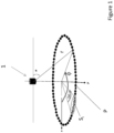
- Such a LIDAR sensor includes several lasers each oriented at a different angle relative to the plane of the vehicle. By rotating, and carrying out several acquisitions during a rotation, the LIDAR sensor determines the position of the reflection points of each laser beam on a surface and generates a cloud of points whose coordinates correspond to the relative positions of the reflection points in relation to to the LIDAR sensor.
- the coordinates of a reflection point P are generally expressed in polar coordinates in the form (r, ⁇ , ⁇ ) with r the distance between the sensor and the reflection point, ⁇ the angle of the beam relative to the vehicle plane and ⁇ the angle of the beam in the plane of the vehicle.
- r the distance between the sensor and the reflection point
- ⁇ the angle of the beam relative to the vehicle plane
- ⁇ the angle of the beam in the plane of the vehicle.
- vehicle plan we mean the plan of the vehicle chassis or a plane parallel to the vehicle chassis.
- the reference linked to the vehicle is linked to the LIDAR reference so that no transformation by rotation is necessary to go from one reference to the other.
- LIDAR sensor As the LIDAR sensor generates a very large cloud of points at each complete rotation, it is necessary to carry out a segmentation in order to limit calculation times. For the remainder of the description, we consider that a point in the point cloud is LIDAR data.
- the LIDAR data is separated according to their angle ⁇ relative to the plane of the vehicle.
- the inventors have recognized that the laser beams emitted for an angle ⁇ relative to the plane of the given vehicle form an ideal circle on a road considered smooth, continuous and almost flat.
- the theoretical coordinates (x th ,y th ,z th ) of the points of the ideal circle are determined depending in particular on the angle ⁇ relative to the plane of the vehicle.
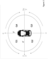
- the LIDAR sensor scans 360° or 2 ⁇ relative to the angle ⁇ in the plane of the vehicle.
- the predefined angular interval can take a value between 1° and 5°.
- the grouping of the points can be carried out by determining an average value of the coordinates of the points of the section.
- the Si sections thus form alternative LIDAR data to the points of the point cloud obtained from the LIDAR sensor.
- Such a grouping of points is carried out within sections Si (i varying from 1 to n, n being the total number of sections) for all points having the same angle ⁇ relative to the plane of the vehicle, before determining the standard deviation ⁇ .
- Equation Eq. 1 and Eq. 2 are expressed in Cartesian coordinates. However, the transformation of these equations into equations expressed in a polar reference frame is part of the general knowledge of those skilled in the art. It is thus possible to maintain a polar reference for all stages of the process.
- a first sector Q1 at the left front of the vehicle we can define a second sector Q2 at the left rear of the vehicle and a third sector Q3 at the right rear of the vehicle and a fourth sector Q4 at the right front of the vehicle.
- LIDAR data which do not correspond to the road, that is to say, LIDAR data for which the standard deviation ⁇ is greater than the predetermined threshold.
- the search is carried out for each sector between the angles and in the direction identified above and up to the angle for which the standard deviation becomes greater than or equal to the predetermined threshold. From then on, we stop the journey of LIDAR data from the sector. The remaining untraveled LIDAR data is considered not part of the route.
- the processing of sectors can be carried out sequentially or simultaneously depending on the number and power of the calculation units.
- a Gaussian filter with the standard deviation ⁇ is applied to each sector Q1,Q2,Q3,Q4 in order to reduce the impact of irregularities before searching for points or sections belonging to the road.
- a size 3, standard deviation 5 core filter is particularly suitable for this use.
- the lane markings are searched as a function of the intensity of the laser beam reflected for each point.
- a LIDAR sensor makes it possible to detect different materials depending on the intensity of the light returned. It is therefore possible to identify lane boundaries on the road using the reflectivity of road markings.
- the intensity associated with each point corresponding to the road is compared to a predetermined threshold.
- the road markings are the points whose intensity is lower than the predetermined threshold which belong to the road.
- a tracking method is used to monitor road boundaries when they are subject to occlusion (by vehicles, for example).
Landscapes
- Physics & Mathematics (AREA)
- Engineering & Computer Science (AREA)
- Electromagnetism (AREA)
- Remote Sensing (AREA)
- General Physics & Mathematics (AREA)
- Radar, Positioning & Navigation (AREA)
- Computer Networks & Wireless Communication (AREA)
- Aviation & Aerospace Engineering (AREA)
- Automation & Control Theory (AREA)
- Optics & Photonics (AREA)
- Traffic Control Systems (AREA)
- Optical Radar Systems And Details Thereof (AREA)
- Length Measuring Devices By Optical Means (AREA)
Applications Claiming Priority (2)
| Application Number | Priority Date | Filing Date | Title |
|---|---|---|---|
| FR1858137A FR3085656B1 (fr) | 2018-09-11 | 2018-09-11 | Procede de detection de route pour un vehicule automobile muni d'un capteur lidar |
| PCT/EP2019/068265 WO2020052830A1 (fr) | 2018-09-11 | 2019-07-08 | Procede de detection de route pour un vehicule automobile muni d'un capteur lidar |
Publications (2)
| Publication Number | Publication Date |
|---|---|
| EP3850397A1 EP3850397A1 (fr) | 2021-07-21 |
| EP3850397B1 true EP3850397B1 (fr) | 2024-01-10 |
Family
ID=65201368
Family Applications (1)
| Application Number | Title | Priority Date | Filing Date |
|---|---|---|---|
| EP19735358.4A Active EP3850397B1 (fr) | 2018-09-11 | 2019-07-08 | Procede de detection de route pour un vehicule automobile muni d'un capteur lidar |
Country Status (7)
| Country | Link |
|---|---|
| US (1) | US20210333397A1 (zh) |
| EP (1) | EP3850397B1 (zh) |
| JP (1) | JP7410932B2 (zh) |
| KR (1) | KR20210048552A (zh) |
| CN (1) | CN112673280A (zh) |
| FR (1) | FR3085656B1 (zh) |
| WO (1) | WO2020052830A1 (zh) |
Families Citing this family (4)
| Publication number | Priority date | Publication date | Assignee | Title |
|---|---|---|---|---|
| US20230271607A1 (en) * | 2022-02-28 | 2023-08-31 | Nissan North America, Inc. | Vehicle lane marking detection system |
| CN116153057A (zh) * | 2022-09-12 | 2023-05-23 | 东北林业大学 | 基于激光雷达点云估算车道宽度的方法 |
| CN115453549A (zh) * | 2022-09-13 | 2022-12-09 | 浙江科聪控制技术有限公司 | 一种基于二维激光雷达的环境直角点坐标角度的提取方法 |
| CN117468941B (zh) * | 2023-12-28 | 2024-03-12 | 四川省铁路建设有限公司 | 基于智能自检台车的隧道缺陷检测方法及自检台车 |
Family Cites Families (8)
| Publication number | Priority date | Publication date | Assignee | Title |
|---|---|---|---|---|
| JP4523095B2 (ja) | 1999-10-21 | 2010-08-11 | 富士通テン株式会社 | 情報処理装置、情報統合装置および情報処理方法 |
| US8699755B2 (en) * | 2009-02-20 | 2014-04-15 | Navteq B.V. | Determining travel path features based on retroreflectivity |
| JP5267592B2 (ja) | 2010-04-09 | 2013-08-21 | 株式会社デンソー | 物体認識装置 |
| JP2012225806A (ja) | 2011-04-20 | 2012-11-15 | Toyota Central R&D Labs Inc | 道路勾配推定装置及びプログラム |
| US9110196B2 (en) * | 2012-09-20 | 2015-08-18 | Google, Inc. | Detecting road weather conditions |
| JP6453701B2 (ja) | 2015-04-23 | 2019-01-16 | 株式会社デンソー | 姿勢推定装置 |
| CN104950313B (zh) | 2015-06-11 | 2017-11-07 | 同济大学 | 一种路面提取及道路坡度识别方法 |
| US20180211119A1 (en) * | 2017-01-23 | 2018-07-26 | Ford Global Technologies, Llc | Sign Recognition for Autonomous Vehicles |
-
2018
- 2018-09-11 FR FR1858137A patent/FR3085656B1/fr active Active
-
2019
- 2019-07-08 KR KR1020217010105A patent/KR20210048552A/ko not_active Application Discontinuation
- 2019-07-08 US US17/274,304 patent/US20210333397A1/en active Pending
- 2019-07-08 JP JP2021513205A patent/JP7410932B2/ja active Active
- 2019-07-08 CN CN201980057927.XA patent/CN112673280A/zh active Pending
- 2019-07-08 WO PCT/EP2019/068265 patent/WO2020052830A1/fr unknown
- 2019-07-08 EP EP19735358.4A patent/EP3850397B1/fr active Active
Also Published As
| Publication number | Publication date |
|---|---|
| EP3850397A1 (fr) | 2021-07-21 |
| WO2020052830A1 (fr) | 2020-03-19 |
| JP7410932B2 (ja) | 2024-01-10 |
| US20210333397A1 (en) | 2021-10-28 |
| CN112673280A (zh) | 2021-04-16 |
| KR20210048552A (ko) | 2021-05-03 |
| JP2022503671A (ja) | 2022-01-12 |
| FR3085656A1 (fr) | 2020-03-13 |
| FR3085656B1 (fr) | 2023-04-28 |
Similar Documents
| Publication | Publication Date | Title |
|---|---|---|
| EP3850397B1 (fr) | Procede de detection de route pour un vehicule automobile muni d'un capteur lidar | |
| FR3041590A1 (fr) | Systeme de commande de la direction d'un vehicule automobile en cas de collision imminente avec un obstacle | |
| EP2043044B1 (fr) | Procédé et dispositif d'assistance au parcage d'un véhicule automobile | |
| EP2161677A1 (fr) | Procédé de détection d'un objet cible pour véhicule automobile | |
| EP1756688B1 (fr) | Procede d'estimation de l'ecart evalue entre la position d'un vehicule et une trajectoire theorique | |
| WO2018060381A1 (fr) | Détection d'obstacles pour véhicule automobile | |
| EP4178842B1 (fr) | Procédé de commande d'un véhicule automobile muni de moyens de conduite autonome | |
| FR3064073A1 (fr) | Procede et dispositif de determination d'une position | |
| FR3054672B1 (fr) | Procede et systeme d'association de donnees de detection et de suivi d'objets mobile pour vehicule automobile | |
| FR3047589A1 (fr) | Procede et dispositif d'estimation de la position laterale d'un vehicule dans une voie de circulation | |
| FR2938228A1 (fr) | Procede de mesure de distance au moyen d'une camera embarquee dans un vehicule automobile | |
| WO2019155134A1 (fr) | Procede de determination de la trajectoire d'un vehicule automobile en absence de marquage au sol. | |
| WO2023061915A1 (fr) | Procédé de détection d'une limite d'une voie de circulation | |
| WO2022033902A1 (fr) | Procédé d'alignement d'au moins deux images formées de points tridimensionnels | |
| WO2022189389A1 (fr) | Procede et dispositif de calibration d'un capteur de profondeur d'environnement | |
| WO2021099395A1 (fr) | Procédé de détection de pics d'intensité de faisceau lumineux réfléchi de manière spéculaire | |
| EP2326999B1 (fr) | Procede de navigation et systeme mettant en oeuvre un tel procede. | |
| EP3865816A1 (fr) | Méthodes et systèmes pour mesurer à distance l'orientation angulaire d'un objet | |
| EP3008664B1 (fr) | Procédé et système de suivi d'objets en mouvement | |
| EP2115542B1 (fr) | Procede de guidage autonome d'un aeronef, et aeronef correspondant | |
| FR3085782A1 (fr) | Procede et dispositif d'identification d'obstacles sur un trajet de vehicule automobile | |
| WO2024003110A1 (fr) | Procédé de détection d'une concavité globale sur une ligne polygonale | |
| EP3394571A1 (fr) | Procédé et dispositif de détermination de positions spatiales et de paramètres cinématiques d'objets dans l'environnement d'un véhicule | |
| FR3141549A1 (fr) | Procede de detection de vehicules longs ou articules | |
| FR3080922A1 (fr) | Dispositif electronique et procede de detection d'un objet via un lidar a balayage, vehicule automobile autonome et programme d'ordinateur associes |
Legal Events
| Date | Code | Title | Description |
|---|---|---|---|
| STAA | Information on the status of an ep patent application or granted ep patent |
Free format text: STATUS: UNKNOWN |
|
| STAA | Information on the status of an ep patent application or granted ep patent |
Free format text: STATUS: THE INTERNATIONAL PUBLICATION HAS BEEN MADE |
|
| PUAI | Public reference made under article 153(3) epc to a published international application that has entered the european phase |
Free format text: ORIGINAL CODE: 0009012 |
|
| STAA | Information on the status of an ep patent application or granted ep patent |
Free format text: STATUS: REQUEST FOR EXAMINATION WAS MADE |
|
| 17P | Request for examination filed |
Effective date: 20210226 |
|
| AK | Designated contracting states |
Kind code of ref document: A1 Designated state(s): AL AT BE BG CH CY CZ DE DK EE ES FI FR GB GR HR HU IE IS IT LI LT LU LV MC MK MT NL NO PL PT RO RS SE SI SK SM TR |
|
| DAV | Request for validation of the european patent (deleted) | ||
| DAX | Request for extension of the european patent (deleted) | ||
| RAP3 | Party data changed (applicant data changed or rights of an application transferred) |
Owner name: RENAULT S.A.S |
|
| RAP3 | Party data changed (applicant data changed or rights of an application transferred) |
Owner name: RENAULT S.A.S |
|
| GRAP | Despatch of communication of intention to grant a patent |
Free format text: ORIGINAL CODE: EPIDOSNIGR1 |
|
| STAA | Information on the status of an ep patent application or granted ep patent |
Free format text: STATUS: GRANT OF PATENT IS INTENDED |
|
| INTG | Intention to grant announced |
Effective date: 20230221 |
|
| P01 | Opt-out of the competence of the unified patent court (upc) registered |
Effective date: 20230608 |
|
| GRAS | Grant fee paid |
Free format text: ORIGINAL CODE: EPIDOSNIGR3 |
|
| GRAA | (expected) grant |
Free format text: ORIGINAL CODE: 0009210 |
|
| STAA | Information on the status of an ep patent application or granted ep patent |
Free format text: STATUS: THE PATENT HAS BEEN GRANTED |
|
| AK | Designated contracting states |
Kind code of ref document: B1 Designated state(s): AL AT BE BG CH CY CZ DE DK EE ES FI FR GB GR HR HU IE IS IT LI LT LU LV MC MK MT NL NO PL PT RO RS SE SI SK SM TR |
|
| REG | Reference to a national code |
Ref country code: GB Ref legal event code: FG4D Free format text: NOT ENGLISH |
|
| REG | Reference to a national code |
Ref country code: CH Ref legal event code: EP |
|
| REG | Reference to a national code |
Ref country code: DE Ref legal event code: R096 Ref document number: 602019044872 Country of ref document: DE |
|
| REG | Reference to a national code |
Ref country code: IE Ref legal event code: FG4D Free format text: LANGUAGE OF EP DOCUMENT: FRENCH |
|
| RAP2 | Party data changed (patent owner data changed or rights of a patent transferred) |
Owner name: AMPERE SAS |
|
| REG | Reference to a national code |
Ref country code: LT Ref legal event code: MG9D |
|
| REG | Reference to a national code |
Ref country code: NL Ref legal event code: MP Effective date: 20240110 |