EP3850178B1 - Schwenkbare vorrichtung für geräte und möbel mit endgeschwindigkeitsdämpfung - Google Patents
Schwenkbare vorrichtung für geräte und möbel mit endgeschwindigkeitsdämpfung Download PDFInfo
- Publication number
- EP3850178B1 EP3850178B1 EP19766027.7A EP19766027A EP3850178B1 EP 3850178 B1 EP3850178 B1 EP 3850178B1 EP 19766027 A EP19766027 A EP 19766027A EP 3850178 B1 EP3850178 B1 EP 3850178B1
- Authority
- EP
- European Patent Office
- Prior art keywords
- closing
- door
- rotation
- crank
- parallel
- Prior art date
- Legal status (The legal status is an assumption and is not a legal conclusion. Google has not performed a legal analysis and makes no representation as to the accuracy of the status listed.)
- Active
Links
- 238000013016 damping Methods 0.000 title claims description 11
- 238000005096 rolling process Methods 0.000 claims description 7
- 230000002093 peripheral effect Effects 0.000 claims description 5
- 239000012530 fluid Substances 0.000 claims description 4
- 230000006835 compression Effects 0.000 claims description 2
- 238000007906 compression Methods 0.000 claims description 2
- 239000002184 metal Substances 0.000 description 4
- 239000011347 resin Substances 0.000 description 2
- 229920005989 resin Polymers 0.000 description 2
- 229910000842 Zamak Inorganic materials 0.000 description 1
- 239000000956 alloy Substances 0.000 description 1
- 229910045601 alloy Inorganic materials 0.000 description 1
- 230000000694 effects Effects 0.000 description 1
- 239000002783 friction material Substances 0.000 description 1
- 239000003292 glue Substances 0.000 description 1
- 238000007493 shaping process Methods 0.000 description 1
- 230000003068 static effect Effects 0.000 description 1
- 229920002994 synthetic fiber Polymers 0.000 description 1
Images


Classifications
-
- E—FIXED CONSTRUCTIONS
- E05—LOCKS; KEYS; WINDOW OR DOOR FITTINGS; SAFES
- E05F—DEVICES FOR MOVING WINGS INTO OPEN OR CLOSED POSITION; CHECKS FOR WINGS; WING FITTINGS NOT OTHERWISE PROVIDED FOR, CONCERNED WITH THE FUNCTIONING OF THE WING
- E05F5/00—Braking devices, e.g. checks; Stops; Buffers
- E05F5/06—Buffers or stops limiting opening of swinging wings, e.g. floor or wall stops
- E05F5/10—Buffers or stops limiting opening of swinging wings, e.g. floor or wall stops with piston brakes
-
- E—FIXED CONSTRUCTIONS
- E05—LOCKS; KEYS; WINDOW OR DOOR FITTINGS; SAFES
- E05D—HINGES OR SUSPENSION DEVICES FOR DOORS, WINDOWS OR WINGS
- E05D7/00—Hinges or pivots of special construction
- E05D7/08—Hinges or pivots of special construction for use in suspensions comprising two spigots placed at opposite edges of the wing, especially at the top and the bottom, e.g. trunnions
- E05D7/081—Hinges or pivots of special construction for use in suspensions comprising two spigots placed at opposite edges of the wing, especially at the top and the bottom, e.g. trunnions the pivot axis of the wing being situated near one edge of the wing, especially at the top and bottom, e.g. trunnions
-
- E—FIXED CONSTRUCTIONS
- E05—LOCKS; KEYS; WINDOW OR DOOR FITTINGS; SAFES
- E05F—DEVICES FOR MOVING WINGS INTO OPEN OR CLOSED POSITION; CHECKS FOR WINGS; WING FITTINGS NOT OTHERWISE PROVIDED FOR, CONCERNED WITH THE FUNCTIONING OF THE WING
- E05F1/00—Closers or openers for wings, not otherwise provided for in this subclass
- E05F1/08—Closers or openers for wings, not otherwise provided for in this subclass spring-actuated, e.g. for horizontally sliding wings
- E05F1/10—Closers or openers for wings, not otherwise provided for in this subclass spring-actuated, e.g. for horizontally sliding wings for swinging wings, e.g. counterbalance
- E05F1/12—Mechanisms in the shape of hinges or pivots, operated by springs
- E05F1/1246—Mechanisms in the shape of hinges or pivots, operated by springs with a coil spring perpendicular to the pivot axis
- E05F1/1269—Mechanisms in the shape of hinges or pivots, operated by springs with a coil spring perpendicular to the pivot axis with a traction spring
-
- E—FIXED CONSTRUCTIONS
- E05—LOCKS; KEYS; WINDOW OR DOOR FITTINGS; SAFES
- E05F—DEVICES FOR MOVING WINGS INTO OPEN OR CLOSED POSITION; CHECKS FOR WINGS; WING FITTINGS NOT OTHERWISE PROVIDED FOR, CONCERNED WITH THE FUNCTIONING OF THE WING
- E05F3/00—Closers or openers with braking devices, e.g. checks; Construction of pneumatic or liquid braking devices
- E05F3/04—Closers or openers with braking devices, e.g. checks; Construction of pneumatic or liquid braking devices with liquid piston brakes
- E05F3/10—Closers or openers with braking devices, e.g. checks; Construction of pneumatic or liquid braking devices with liquid piston brakes with a spring, other than a torsion spring, and a piston, the axes of which are the same or lie in the same direction
- E05F3/104—Closers or openers with braking devices, e.g. checks; Construction of pneumatic or liquid braking devices with liquid piston brakes with a spring, other than a torsion spring, and a piston, the axes of which are the same or lie in the same direction with cam-and-slide transmission between driving shaft and piston within the closer housing
-
- E—FIXED CONSTRUCTIONS
- E05—LOCKS; KEYS; WINDOW OR DOOR FITTINGS; SAFES
- E05Y—INDEXING SCHEME RELATING TO HINGES OR OTHER SUSPENSION DEVICES FOR DOORS, WINDOWS OR WINGS AND DEVICES FOR MOVING WINGS INTO OPEN OR CLOSED POSITION, CHECKS FOR WINGS AND WING FITTINGS NOT OTHERWISE PROVIDED FOR, CONCERNED WITH THE FUNCTIONING OF THE WING
- E05Y2201/00—Constructional elements; Accessories therefore
- E05Y2201/60—Suspension or transmission members; Accessories therefore
- E05Y2201/622—Suspension or transmission members elements
- E05Y2201/624—Arms
- E05Y2201/626—Levers
-
- E—FIXED CONSTRUCTIONS
- E05—LOCKS; KEYS; WINDOW OR DOOR FITTINGS; SAFES
- E05Y—INDEXING SCHEME RELATING TO HINGES OR OTHER SUSPENSION DEVICES FOR DOORS, WINDOWS OR WINGS AND DEVICES FOR MOVING WINGS INTO OPEN OR CLOSED POSITION, CHECKS FOR WINGS AND WING FITTINGS NOT OTHERWISE PROVIDED FOR, CONCERNED WITH THE FUNCTIONING OF THE WING
- E05Y2201/00—Constructional elements; Accessories therefore
- E05Y2201/60—Suspension or transmission members; Accessories therefore
- E05Y2201/622—Suspension or transmission members elements
- E05Y2201/638—Cams; Ramps
-
- E—FIXED CONSTRUCTIONS
- E05—LOCKS; KEYS; WINDOW OR DOOR FITTINGS; SAFES
- E05Y—INDEXING SCHEME RELATING TO HINGES OR OTHER SUSPENSION DEVICES FOR DOORS, WINDOWS OR WINGS AND DEVICES FOR MOVING WINGS INTO OPEN OR CLOSED POSITION, CHECKS FOR WINGS AND WING FITTINGS NOT OTHERWISE PROVIDED FOR, CONCERNED WITH THE FUNCTIONING OF THE WING
- E05Y2900/00—Application of doors, windows, wings or fittings thereof
- E05Y2900/30—Application of doors, windows, wings or fittings thereof for domestic appliances
Definitions
- the present invention relates to the technical field concerning hinges and refers to a hinge device with damping of the closing or opening end speed and optionally having pre-fixed angular sectors of elastic opening and/or closure, for equipment, such for example household appliances, and for doors, windows and furnishings, with hatches, doors, flaps or swinging doors around vertical or horizontal hinge axis, capable of imparting to these hatches prefixed speed damping forces and elastic closing and/or opening forces, particularly, but not exclusively suitable for refrigerators.
- the known hinges for doors of vertical refrigerators are usually each constituted by a bracket fixed to the frame or body of the refrigerator and having a vertical axis hole for a vertical hinge pin that engages in a respective cylindrical seat with vertical axis fixed to the door or refrigerator door.
- An object of the present invention is to propose a hinge device for refrigerators and furniture with a vertical hinge axis that, at the same time, is very compact so that it can also be installed in current refrigerators, appliances and furnishings and able to dampen the speed of the end closing stroke of the door.
- Another object is to propose a configurable hinge device for damping the end opening speed of the door.
- a further object is to provide a device fit for applying to the door a resilient force for closing and/or opening or metastable positioning in angular sectors or in predeterminable angular positions.
- Another object is to propose a device capable of braking the door homogeneously or according to the door angle.
- a further object is to propose a device capable of braking the angular speed of the door.
- Another object is to propose a device that can be installed in equipment and furnishings with one or more doors or doors with vertical rotation axis, such as refrigerators and some vertical furnishings, or horizontal, such as ovens, cockpit fridges and furniture with flap doors.
- the present invention comprises parts and elements which simultaneously carry out several operative functions, contributing synergistically to the reduction of overall dimensions and costs.
- numeral 1 indicates the hinge device for equipment and furnishings with damping of the closing speed and with pre-fixed angular sectors for elastic opening and/or closing for refrigerators, for other household appliances and in general for equipment and furnishings, with one or more flaps or doors A, for example with a vertical or horizontal rotation axis, object of the present invention (and for the sake of brevity, also referred to as a hinge device or simply a device);
- the term refrigerator will be used to indicate generally also other household appliances, apparatus and furnishings such as electric, gas and microwave ovens, dishwashers, kitchen cupboards, fixtures, furniture and the like.
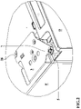
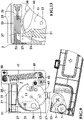
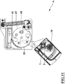
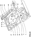
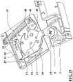
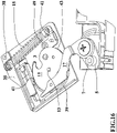
- the hinge device 1 comprises, in an operating condition of assembly to the refrigerator or apparatus, a first element 3, consisting of a metal frame, for example in the form of a box or shaped plate, fixed to a body F of the apparatus and a second element 5 fixed to a door D of said apparatus or formed in this door D where these elements first 3 and second 5 are mutually connected by a hinge pivot 7 for the rotation of the door around the longitudinal geometric axis of said hinge pivot 7 between opening A and closing C conditions.
- a first element 3 consisting of a metal frame, for example in the form of a box or shaped plate, fixed to a body F of the apparatus and a second element 5 fixed to a door D of said apparatus or formed in this door D where these elements first 3 and second 5 are mutually connected by a hinge pivot 7 for the rotation of the door around the longitudinal geometric axis of said hinge pivot 7 between opening A and closing C conditions.
- the second element 5 consists of a small metal plate fixed to the upper, lower or lateral edge of the respective door D for example by means of the hinge pivot 7 and/or a second rotation pin 19, better identified in the following, fixed or screwed to the door D; alternatively or additionally, this small metal plate can be fixed to the door by glue or resin. Alternatively, the second element 5 can be integrated or incorporated into the door D or wing.
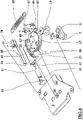
- Said device 1 comprises a crank means 11 of approximately disk-shaped form and connected to the frame of the first element 3 by one of its 11 first rotation pin 13 almost central to the crank means 11 itself.
- the first rotation pin 13 is parallel to the hinge pivot 7 and is perpendicular to the geometric plane of the crank means 11.
- the crank means 11 can be, for example, made of bent and sheared sheet metal.
- the device 1 also comprises a connecting rod means 17, for example, made of bent and sheared sheet and having an approximately "S" shaped form, having an end rotatably connected to the second element 5 through said second rotation pin 19 which is parallel and spaced apart from the hinge pivot 7.
- This connecting rod means 17 is also rotatably connected to the crank means 11 by means of a third rotation pin 21 parallel and distanced from the first rotation pin 13.
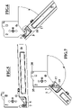
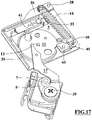
- the figures illustrate the device configured to dampen the speed of the terminal rotation section for closing the door or leaf and the third rotation pin 21 is located, with respect to the first rotation pin 13, on the same side as the hinge pivot 7.
- the portion of the connecting rod means 17 carrying the third rotation pin 21 has an arm means 27, for example consisting in an elongation or protrusion of the connecting rod means 17 itself, protruding with respect to the third rotation pin 21 in the opposite direction to the second rotation pin 19 or at least approximately parallel to the longitudinal development of the connecting rod means 17.
- the arm means 27 can be approximately aligned with the geometric line connecting the second rotation pin 19 to the third rotation pin 21.
- the arm means 27 is assigned to move in one of its closing directions at the end portion of the closing rotation of the door D.
- an arm means 27 closure direction may be approximately tangent to the crank means 11 and/or parallel to the door or flap D closed and/or almost closed.
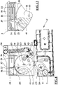
- the device 1 comprises a damper means 31 of the linear type housed in a respective housing means 33, and is opposed to the second rotation pin 19 with respect to the first rotation pin 13 and is approximately oriented parallel to said closure direction of the arm means 27 which, during said movement, abuts with a mobile member 37 of the damper means 31, damping the translation of the connecting rod means 17 and the rotation of the end portion for closing the door.
- the arm means 27 can be oriented so that, during the end portion of the closing rotation of the door D, its 27 longitudinal extension is approximately perpendicular to the direction of its own closing movement or to the longitudinal axis of the damper means 31 or this extension is slightly inclined towards the damper means 31 and during this rotation portion, the movement of the arm means 27 has a component in accordance with the compression direction of the damper means 31.
- the housing means 33 has a hollow housing 57 for the damper means 31 which can be partially closed by a closure means 51 which prevents the damper means 31 from coming out of the hollow housing 57 and which is provided with a window for the free passage of the arm means 27.
- the linear damper means 31 can be, for example, of the type having an internally provided body with a chamber having a fluid and in which a piston equipped with a stem projecting externally from the body and where an elastic means pushes the stem outwards the chamber and the fluid acts with viscous friction onto the piston;
- the mobile member 37 of the damper means 31 can consist, for example, in the external head of the stem or, as shown in the figures, in the body of the damper means.
- the invention provides, for example, that the third rotation pin 21 is connected to the half of the crank means 11 opposite to the hinge pivot 7 with respect to the first rotation pin 13, that the damper means 31 is on the same side as the hinge pivot 7 with respect to the first rotation pin 13 and that the arm means 27 is bent to meet with the movable part of the damper means 31 to dampen the end portion of the end opening rotation of the door where such opening and closing damping functions can also be implemented with other equivalent arrangements of the device elements.
- the device 1 comprises a resilient means 15, for example consisting of a helical spring operating in elongation, connected to the first element 3 and acting on the crank means 11 to transmit to the latter a respective elastic force acting in closing and/or in openings of the door D.
- a resilient means for example consisting of a helical spring operating in elongation
- the resilient means 15 can act directly onto the crank means 11, for example through a connection pin, but preferably and to modulate the action of the elastic force on the door, the resilient means 15 acts on the crank means 11 by means of the connection of one of its 15 ends, opposite to that connected to the first element 3, at one end of a rocker arm 45 centrally connected to the first element 3 by means of a respective fulcrum pin 47 parallel to the hinge pivot 7 and having, at opposite end, a rolling means 49, for example consisting of an idle wheel, with an axis of rotation parallel to the hinge pivot 7 and rolling on a shaped peripheral edge cam 43 of the crank means 11, as shown in the figures. Therefore the peripheral edge cam 43, of the crank means 11, can be shaped so that the rolling means transmits elastic forces directed towards the closure, the opening or to realize metastable positions of the door.
- the peripheral edge cam 43 of the crank means 11, at the position of the rolling means 49 in at least one of the end portions for opening and closing said edge has a corresponding shaping, for example with recess, to impart to the crank means 11 a force respectively for opening or closing the door D.
- the resilient means 15 is connected to the first element 3 by fixing one of its 15 ends, opposite to that connected to the rocker arm, to a lever means 35 rotatably connected to the first element 3 through a respective fulcrum pin 38 parallel to the hinge pivot 7.
- the housing means 33 of the damper means 31 is fixed to the lever means 35 and the crank means 11 has an edge 39 hemmed or rimmed, of an approximately arc shape intended to slide with friction on a friction surface 41 of the housing means 33 where the resilient means 15 transmits to the lever means 35 an elastic force which maintains said friction surface 41 in abutment with said edge 39.
- the housing means 33 is made of synthetic material, plastic, simple or reinforced resin, or in alloy, for example zamak, and its friction surface 41 can be treated or coated with friction material so as to determine the friction coefficient according to the specific use requirements of the device.
- the static and dynamic clutches between the rimmed edge 39 and the friction surface 41 brake the door and, if appropriate, can stabilize its position in any angular position.
- the invention provides that it is possible to shape the rimmed edge 39 to modulate the braking effect as a function of the opening angle of the door or flap.
- crank means 11 is constituted by two nearly equal, parallel and spaced apart disc-shaped bodies and the connecting rod means 17 is placed between them; this arrangement allows to increase the contact and friction surface between the double edge 39 and the friction surface 41 and at the same time avoids excessive warping of the connecting rod means 17.
Claims (10)
- Scharniervorrichtung für Anwendungen und Einrichtungen mit Endgeschwindigkeitsdämpfung für das Schließen oder Öffnen, und mit vorbestimmbaren Winkelbereichen des elastischen Öffnens und/oder Schließens; wobei die Scharniervorrichtung (1) in einem Montage-Betriebszustand an die Anwendung ein erstes Element (3) umfasst, das an einem Körper (F) des Geräts befestigt ist und ein zweites Element (5), das an einer Tür (D) des Geräts befestigt ist oder in der Tür (D) erhalten wird, bei dem das erste (3) und das zweite (5) Element miteinander durch einen Scharnierzapfen (7) verbunden sind zur Drehung der Tür um die geometrische Längsachse des Scharnierzapfens (7) zwischen End-öffnungs- (A) und Schließbedingungen (C); die Vorrichtung (1) umfasst ein Kurbelmittel (11), das drehbar mit dem ersten Element (3) mittels eines seiner fast zentralen Drehstifte (13) parallel zu dem Scharnierzapfen (7) verbunden ist und umfasst ein verbindendes Stangenmittel (17), das ein drehbares Ende aufweist, das mit dem zweiten Element (5) verbunden ist mittels eines zweiten Drehstifts (19) parallel zu und beabstandet von dem Scharnierzapfen (7); wobei das Verbindungsstangenmittel (17) ebenso drehbar mit dem Kurbelmittel (11) mittels eines dritten Drehstifts (21) parallel zu und beabstandet von dem ersten Drehstift (13) verbunden ist; wobei der Bereich des Verbindungsstangenmittels (17), der den dritten Drehstift (21) trägt, ein Armmittel (27) umfasst, das in entgegengesetzter Richtung von dem zweiten Drehstift (19) vorsteht oder zumindest annähernd parallel zu der Längserstreckung des Verbindungsstangenmittels (17) und so gestaltet ist, dass es sich in einer Schließrichtung an mindestens dem Endbereich der Schließdrehung der Tür (D) bewegt und wobei die Scharniervorrichtung (1) ein Dämpfermittel (31) des linearen Typs aufweist, das in einem entsprechenden Gehäusemittel (33) aufgenommen ist und ungefähr parallel zu der Schließrichtung des Armmittels (27) ausgerichtet ist, das während der Bewegung zu einem mobilen Element (37) des Dämpfermittels (31) passt, das die Übertragung des Verbindungsstangenmittels (17) und die Drehung des Endschließbereichs der Tür dämpft.
- Vorrichtung nach Anspruch 1, dadurch gekennzeichnet, dass sie ein federndes Mittel (15) umfasst, das mit dem ersten Element (3) verbunden ist und auf Kurbelmittel (11) wirkt, um auf letztere eine entsprechende Elastische Kraft zu übertragen, die beim Schließen und/oder Öffnen der Tür (D) wirkt.
- Vorrichtung nach Anspruch 2, dadurch gekennzeichnet, dass das federnde Mittel (15) mit dem ersten Element (3) verbunden ist, indem ein Ende des federnden Mittels (15) an einem Hebelmittel (35) befestigt wird, das drehbar mit dem ersten Element (3) mittels eines entsprechenden Gelenkstifts (38) parallel zu dem Scharnierzapfen (7) verbunden ist.
- Vorrichtung nach Anspruch 3, dadurch gekennzeichnet, dass das Gehäusemittel (33) des Dämpfermittels (31) an dem Hebelmittel (35) befestigt ist und das Kurbelmittel (11) weist eine grob bogenförmige Kante (39) auf, die so ausgeführt ist, dass sie mit Reibung auf einer Reibungsoberfläche (41) des Gehäusemittels (33) gleitet, wo das federnde Mittel (15) eine elastische Kraft auf das Hebelmittel (35) überträgt, das die Reibungsoberfläche (41) in Anschlag mit der Kante (39) hält.
- Vorrichtung nach Anspruch 2 oder Anspruch 3, dadurch gekennzeichnet, dass das federnde Mittel (15) auf das Kurbelmittel (11) wirkt, durch Verbinden eines Endes des federnden Mittels (15) mit einem Ende eines Kipphebels (45), der mittig mit dem ersten Element (3) mittels eines entsprechenden Gelenkstifts (47) parallel zu dem Scharnierzapfen (7) verbunden ist und weist an dem gegenüberliegenden Ende ein Rollmittel (49) mit einer Drehungsachse parallel zu dem Scharnierzapfen (7) auf und rollt auf einer geformten peripheren Kantennocke (43) des Kurbelmittels (11).
- Vorrichtung nach Anspruch 5, dadurch gekennzeichnet, dass die periphere Kantennocke (43) des Kurbelmittels (11) an der Position des Rollmittels (49) in mindestens einem der Öffnungs- und Schließendbereiche der Kante mindestens eine Form aufweist, um die elastische Kraft des federnden Mittels (15) zu übertragen, wodurch das Kurbelmittel mit einer Kraft zum Öffnen bzw. Schließen der Türe (D) bereitgestellt wird.
- Vorrichtung nach einem der vorhergehenden Ansprüche, dadurch gekennzeichnet, dass zumindest während des Endbereichs der Schließdrehung der Türe (D) die Längserstreckung des Armmittels (27) ungefähr senkrecht zu der Richtung seiner Schließbewegung oder zu der Längsachse des Dämpfermittels (31) ist oder eine solche Erstreckung ist geringfügig in Richtung des Dämpfermittels (31) geneigt und weist während dieses Drehbereichs die Bewegung des Armmittels (27) einen Bestandteil in Übereinstimmung mit der Kompressionsrichtung des Dämpfermittels (31) auf.
- Vorrichtung nach einem der vorhergehenden Ansprüche, dadurch gekennzeichnet, dass das lineare Dämpfermittel (31) von der Art ist, die einen Körper aufweist, der im Inneren mit einer Kammer versehen ist, die ein Fluid enthält und in der ein Zapfen mit einem Stamm gleitet, der nach außen von dem Körper absteht und bei dem ein federndes Mittel den Stamm aus der Kammer herauspresst und das Fluid mit viskoser Reibung auf den Zapfen wirkt.
- Vorrichtung nach einem der vorhergehenden Ansprüche, dadurch gekennzeichnet, dass das Gehäusemittel (33) ein hohles Gehäuse (57) für das Dämpfermittel (31) aufweist und teilweise durch ein Schließmittel schließbar ist, was das Dämpfermittel (31) daran hindert, aus dem hohlen Gehäuse (57) zu treten, und ist ausgestattet mit einem Fenster für den freien Durchgang des Armmittels (27).
- Vorrichtung nach einem der vorhergehenden Ansprüche, dadurch gekennzeichnet, dass das Kurbelmittel (11) aus zwei nahezu gleichen, parallelen und beabstandeten scheibenartigen Körpern besteht und das Verbindungsstangenmittel (17) ist dazwischen angeordnet.
Applications Claiming Priority (2)
| Application Number | Priority Date | Filing Date | Title |
|---|---|---|---|
| IT201800008630 | 2018-09-14 | ||
| PCT/EP2019/074402 WO2020053352A1 (en) | 2018-09-14 | 2019-09-12 | Hinged device for appliances and furnishings with end speed damping |
Publications (2)
| Publication Number | Publication Date |
|---|---|
| EP3850178A1 EP3850178A1 (de) | 2021-07-21 |
| EP3850178B1 true EP3850178B1 (de) | 2022-11-23 |
Family
ID=64427114
Family Applications (1)
| Application Number | Title | Priority Date | Filing Date |
|---|---|---|---|
| EP19766027.7A Active EP3850178B1 (de) | 2018-09-14 | 2019-09-12 | Schwenkbare vorrichtung für geräte und möbel mit endgeschwindigkeitsdämpfung |
Country Status (3)
| Country | Link |
|---|---|
| EP (1) | EP3850178B1 (de) |
| CN (1) | CN112739881B (de) |
| WO (1) | WO2020053352A1 (de) |
Families Citing this family (2)
| Publication number | Priority date | Publication date | Assignee | Title |
|---|---|---|---|---|
| IT202000018073A1 (it) * | 2020-07-27 | 2022-01-27 | Danco S P A | Cerniera a un perno per porte e/o ante di mobili o articoli di arredamento |
| EP3945193A1 (de) * | 2020-07-27 | 2022-02-02 | Danco S.p.A. | Einstiftscharnier für türen und/oder paneele von möbeln oder einrichtungsgegenständen |
Citations (3)
| Publication number | Priority date | Publication date | Assignee | Title |
|---|---|---|---|---|
| EP2547853B1 (de) * | 2010-03-17 | 2016-06-01 | Hettich-Heinze GmbH & Co. KG | Rollenführung |
| EP3114297B1 (de) * | 2014-03-07 | 2019-12-04 | Hettich-Heinze GmbH & Co. KG | Führungsvorrichtung |
| DE202020101165U1 (de) * | 2020-03-03 | 2020-03-12 | Häfele GmbH & Co KG | Laufschiene in Form eines gewalzten Blechprofils |
Family Cites Families (8)
| Publication number | Priority date | Publication date | Assignee | Title |
|---|---|---|---|---|
| DE102005018552A1 (de) | 2005-04-20 | 2006-11-02 | Huwil-Werke Gmbh Möbelschloss- Und Beschlagfabriken | Halteelement |
| ITBO20050564A1 (it) | 2005-09-14 | 2007-03-15 | Cmi Srl | Dispositivo compatto a cerniera per un portello |
| DE202006010482U1 (de) * | 2006-07-06 | 2007-11-08 | Liebherr-Hausgeräte Lienz Gmbh | Anordnung zur schwenkbaren Lagerung einer Tür oder Klappe sowie Kühl- und/oder Gefriergeräte mit einer derartigen Anordnung |
| DE102009022737A1 (de) | 2009-05-26 | 2011-03-31 | Zimmer, Günther | Scharnier für Klappentüren |
| ITMI20091742A1 (it) * | 2009-10-13 | 2011-04-14 | Salice Arturo Spa | Struttura di cerniera decelerata per mobile con ripiano a ribalta |
| DE102014101849A1 (de) * | 2014-02-13 | 2015-08-13 | Hettich-Oni Gmbh & Co. Kg | Lageranordnung für eine Tür |
| DE102015103234A1 (de) * | 2015-03-05 | 2016-09-08 | Hettich-Oni Gmbh & Co. Kg | Haushaltsgerät und Scharnier eines Haushaltsgeräts |
| ITUB20155424A1 (it) * | 2015-11-10 | 2017-05-10 | C M I Cerniere Mecc Industriali Srl | Dispositivo a cerniera con possibilita di apertura a sfiato |
-
2019
- 2019-09-12 WO PCT/EP2019/074402 patent/WO2020053352A1/en unknown
- 2019-09-12 EP EP19766027.7A patent/EP3850178B1/de active Active
- 2019-09-12 CN CN201980059010.3A patent/CN112739881B/zh active Active
Patent Citations (3)
| Publication number | Priority date | Publication date | Assignee | Title |
|---|---|---|---|---|
| EP2547853B1 (de) * | 2010-03-17 | 2016-06-01 | Hettich-Heinze GmbH & Co. KG | Rollenführung |
| EP3114297B1 (de) * | 2014-03-07 | 2019-12-04 | Hettich-Heinze GmbH & Co. KG | Führungsvorrichtung |
| DE202020101165U1 (de) * | 2020-03-03 | 2020-03-12 | Häfele GmbH & Co KG | Laufschiene in Form eines gewalzten Blechprofils |
Also Published As
| Publication number | Publication date |
|---|---|
| CN112739881A (zh) | 2021-04-30 |
| WO2020053352A1 (en) | 2020-03-19 |
| EP3850178A1 (de) | 2021-07-21 |
| CN112739881B (zh) | 2022-07-19 |
Similar Documents
| Publication | Publication Date | Title |
|---|---|---|
| US11111712B2 (en) | Appliance lid hinge | |
| US20130221825A1 (en) | Controlled closure system for a hinge | |
| US9879462B2 (en) | Hinge assemblies | |
| CA2778726C (en) | Domestic appliance hinge assembly with double linkage | |
| EP3850178B1 (de) | Schwenkbare vorrichtung für geräte und möbel mit endgeschwindigkeitsdämpfung | |
| RU2674189C2 (ru) | Холодильный или морозильный шкаф | |
| US10633904B2 (en) | Domestic appliance hinge assembly with cylinder alignment shoulder bushing | |
| US8707519B2 (en) | Domestic appliance hinge assembly with universal hinge body design | |
| US20130300273A1 (en) | Hinge assembly for domestic appliance including spring having low-friction coating | |
| US11702878B2 (en) | Damped and compact hinge device | |
| CA2779919C (en) | Domestic appliance hinge assembly with hinge keeper | |
| CA2778632C (en) | Hinge assembly for domestic appliance | |
| WO2019211435A1 (en) | Hinge device for refrigerator and furnishings | |
| US20130312220A1 (en) | Domestic appliance hinge assembly with damper alignment spacer bushings | |
| CN114258449A (zh) | 具有阻尼器的用于受控地关闭和打开门的铰链 | |
| US11306526B2 (en) | Hinges |
Legal Events
| Date | Code | Title | Description |
|---|---|---|---|
| STAA | Information on the status of an ep patent application or granted ep patent |
Free format text: STATUS: UNKNOWN |
|
| STAA | Information on the status of an ep patent application or granted ep patent |
Free format text: STATUS: THE INTERNATIONAL PUBLICATION HAS BEEN MADE |
|
| PUAI | Public reference made under article 153(3) epc to a published international application that has entered the european phase |
Free format text: ORIGINAL CODE: 0009012 |
|
| STAA | Information on the status of an ep patent application or granted ep patent |
Free format text: STATUS: REQUEST FOR EXAMINATION WAS MADE |
|
| 17P | Request for examination filed |
Effective date: 20210414 |
|
| AK | Designated contracting states |
Kind code of ref document: A1 Designated state(s): AL AT BE BG CH CY CZ DE DK EE ES FI FR GB GR HR HU IE IS IT LI LT LU LV MC MK MT NL NO PL PT RO RS SE SI SK SM TR |
|
| DAV | Request for validation of the european patent (deleted) | ||
| DAX | Request for extension of the european patent (deleted) | ||
| REG | Reference to a national code |
Ref country code: DE Ref legal event code: R079 Ref document number: 602019022272 Country of ref document: DE Free format text: PREVIOUS MAIN CLASS: E05F0001120000 Ipc: E05D0007081000 |
|
| RIC1 | Information provided on ipc code assigned before grant |
Ipc: E05F 5/10 20060101ALI20220428BHEP Ipc: E05F 3/10 20060101ALI20220428BHEP Ipc: E05F 1/12 20060101ALI20220428BHEP Ipc: E05D 7/081 20060101AFI20220428BHEP |
|
| GRAP | Despatch of communication of intention to grant a patent |
Free format text: ORIGINAL CODE: EPIDOSNIGR1 |
|
| STAA | Information on the status of an ep patent application or granted ep patent |
Free format text: STATUS: GRANT OF PATENT IS INTENDED |
|
| INTG | Intention to grant announced |
Effective date: 20220613 |
|
| GRAS | Grant fee paid |
Free format text: ORIGINAL CODE: EPIDOSNIGR3 |
|
| GRAA | (expected) grant |
Free format text: ORIGINAL CODE: 0009210 |
|
| STAA | Information on the status of an ep patent application or granted ep patent |
Free format text: STATUS: THE PATENT HAS BEEN GRANTED |
|
| AK | Designated contracting states |
Kind code of ref document: B1 Designated state(s): AL AT BE BG CH CY CZ DE DK EE ES FI FR GB GR HR HU IE IS IT LI LT LU LV MC MK MT NL NO PL PT RO RS SE SI SK SM TR |
|
| REG | Reference to a national code |
Ref country code: GB Ref legal event code: FG4D |
|
| REG | Reference to a national code |
Ref country code: CH Ref legal event code: EP |
|
| REG | Reference to a national code |
Ref country code: DE Ref legal event code: R096 Ref document number: 602019022272 Country of ref document: DE |
|
| REG | Reference to a national code |
Ref country code: AT Ref legal event code: REF Ref document number: 1533234 Country of ref document: AT Kind code of ref document: T Effective date: 20221215 |
|
| REG | Reference to a national code |
Ref country code: IE Ref legal event code: FG4D |
|
| REG | Reference to a national code |
Ref country code: LT Ref legal event code: MG9D |
|
| REG | Reference to a national code |
Ref country code: NL Ref legal event code: MP Effective date: 20221123 |
|
| REG | Reference to a national code |
Ref country code: AT Ref legal event code: MK05 Ref document number: 1533234 Country of ref document: AT Kind code of ref document: T Effective date: 20221123 |
|
| PG25 | Lapsed in a contracting state [announced via postgrant information from national office to epo] |
Ref country code: SE Free format text: LAPSE BECAUSE OF FAILURE TO SUBMIT A TRANSLATION OF THE DESCRIPTION OR TO PAY THE FEE WITHIN THE PRESCRIBED TIME-LIMIT Effective date: 20221123 Ref country code: PT Free format text: LAPSE BECAUSE OF FAILURE TO SUBMIT A TRANSLATION OF THE DESCRIPTION OR TO PAY THE FEE WITHIN THE PRESCRIBED TIME-LIMIT Effective date: 20230323 Ref country code: NO Free format text: LAPSE BECAUSE OF FAILURE TO SUBMIT A TRANSLATION OF THE DESCRIPTION OR TO PAY THE FEE WITHIN THE PRESCRIBED TIME-LIMIT Effective date: 20230223 Ref country code: LT Free format text: LAPSE BECAUSE OF FAILURE TO SUBMIT A TRANSLATION OF THE DESCRIPTION OR TO PAY THE FEE WITHIN THE PRESCRIBED TIME-LIMIT Effective date: 20221123 Ref country code: FI Free format text: LAPSE BECAUSE OF FAILURE TO SUBMIT A TRANSLATION OF THE DESCRIPTION OR TO PAY THE FEE WITHIN THE PRESCRIBED TIME-LIMIT Effective date: 20221123 Ref country code: ES Free format text: LAPSE BECAUSE OF FAILURE TO SUBMIT A TRANSLATION OF THE DESCRIPTION OR TO PAY THE FEE WITHIN THE PRESCRIBED TIME-LIMIT Effective date: 20221123 Ref country code: AT Free format text: LAPSE BECAUSE OF FAILURE TO SUBMIT A TRANSLATION OF THE DESCRIPTION OR TO PAY THE FEE WITHIN THE PRESCRIBED TIME-LIMIT Effective date: 20221123 |
|
| PG25 | Lapsed in a contracting state [announced via postgrant information from national office to epo] |
Ref country code: RS Free format text: LAPSE BECAUSE OF FAILURE TO SUBMIT A TRANSLATION OF THE DESCRIPTION OR TO PAY THE FEE WITHIN THE PRESCRIBED TIME-LIMIT Effective date: 20221123 Ref country code: PL Free format text: LAPSE BECAUSE OF FAILURE TO SUBMIT A TRANSLATION OF THE DESCRIPTION OR TO PAY THE FEE WITHIN THE PRESCRIBED TIME-LIMIT Effective date: 20221123 Ref country code: LV Free format text: LAPSE BECAUSE OF FAILURE TO SUBMIT A TRANSLATION OF THE DESCRIPTION OR TO PAY THE FEE WITHIN THE PRESCRIBED TIME-LIMIT Effective date: 20221123 Ref country code: IS Free format text: LAPSE BECAUSE OF FAILURE TO SUBMIT A TRANSLATION OF THE DESCRIPTION OR TO PAY THE FEE WITHIN THE PRESCRIBED TIME-LIMIT Effective date: 20230323 Ref country code: HR Free format text: LAPSE BECAUSE OF FAILURE TO SUBMIT A TRANSLATION OF THE DESCRIPTION OR TO PAY THE FEE WITHIN THE PRESCRIBED TIME-LIMIT Effective date: 20221123 Ref country code: GR Free format text: LAPSE BECAUSE OF FAILURE TO SUBMIT A TRANSLATION OF THE DESCRIPTION OR TO PAY THE FEE WITHIN THE PRESCRIBED TIME-LIMIT Effective date: 20230224 |
|
| PG25 | Lapsed in a contracting state [announced via postgrant information from national office to epo] |
Ref country code: NL Free format text: LAPSE BECAUSE OF FAILURE TO SUBMIT A TRANSLATION OF THE DESCRIPTION OR TO PAY THE FEE WITHIN THE PRESCRIBED TIME-LIMIT Effective date: 20221123 |
|
| PG25 | Lapsed in a contracting state [announced via postgrant information from national office to epo] |
Ref country code: SM Free format text: LAPSE BECAUSE OF FAILURE TO SUBMIT A TRANSLATION OF THE DESCRIPTION OR TO PAY THE FEE WITHIN THE PRESCRIBED TIME-LIMIT Effective date: 20221123 Ref country code: RO Free format text: LAPSE BECAUSE OF FAILURE TO SUBMIT A TRANSLATION OF THE DESCRIPTION OR TO PAY THE FEE WITHIN THE PRESCRIBED TIME-LIMIT Effective date: 20221123 Ref country code: EE Free format text: LAPSE BECAUSE OF FAILURE TO SUBMIT A TRANSLATION OF THE DESCRIPTION OR TO PAY THE FEE WITHIN THE PRESCRIBED TIME-LIMIT Effective date: 20221123 Ref country code: DK Free format text: LAPSE BECAUSE OF FAILURE TO SUBMIT A TRANSLATION OF THE DESCRIPTION OR TO PAY THE FEE WITHIN THE PRESCRIBED TIME-LIMIT Effective date: 20221123 Ref country code: CZ Free format text: LAPSE BECAUSE OF FAILURE TO SUBMIT A TRANSLATION OF THE DESCRIPTION OR TO PAY THE FEE WITHIN THE PRESCRIBED TIME-LIMIT Effective date: 20221123 |
|
| REG | Reference to a national code |
Ref country code: DE Ref legal event code: R097 Ref document number: 602019022272 Country of ref document: DE |
|
| PG25 | Lapsed in a contracting state [announced via postgrant information from national office to epo] |
Ref country code: SK Free format text: LAPSE BECAUSE OF FAILURE TO SUBMIT A TRANSLATION OF THE DESCRIPTION OR TO PAY THE FEE WITHIN THE PRESCRIBED TIME-LIMIT Effective date: 20221123 Ref country code: AL Free format text: LAPSE BECAUSE OF FAILURE TO SUBMIT A TRANSLATION OF THE DESCRIPTION OR TO PAY THE FEE WITHIN THE PRESCRIBED TIME-LIMIT Effective date: 20221123 |
|
| PLBE | No opposition filed within time limit |
Free format text: ORIGINAL CODE: 0009261 |
|
| STAA | Information on the status of an ep patent application or granted ep patent |
Free format text: STATUS: NO OPPOSITION FILED WITHIN TIME LIMIT |
|
| PGFP | Annual fee paid to national office [announced via postgrant information from national office to epo] |
Ref country code: TR Payment date: 20230920 Year of fee payment: 5 Ref country code: IT Payment date: 20230831 Year of fee payment: 5 |
|
| 26N | No opposition filed |
Effective date: 20230824 |
|
| PG25 | Lapsed in a contracting state [announced via postgrant information from national office to epo] |
Ref country code: SI Free format text: LAPSE BECAUSE OF FAILURE TO SUBMIT A TRANSLATION OF THE DESCRIPTION OR TO PAY THE FEE WITHIN THE PRESCRIBED TIME-LIMIT Effective date: 20221123 |
|
| PGFP | Annual fee paid to national office [announced via postgrant information from national office to epo] |
Ref country code: FR Payment date: 20230926 Year of fee payment: 5 Ref country code: DE Payment date: 20230928 Year of fee payment: 5 |