EP3849439B1 - Inverting thrombectomy apparatuses - Google Patents
Inverting thrombectomy apparatuses Download PDFInfo
- Publication number
- EP3849439B1 EP3849439B1 EP19773315.7A EP19773315A EP3849439B1 EP 3849439 B1 EP3849439 B1 EP 3849439B1 EP 19773315 A EP19773315 A EP 19773315A EP 3849439 B1 EP3849439 B1 EP 3849439B1
- Authority
- EP
- European Patent Office
- Prior art keywords
- funnel
- catheter
- inversion support
- distal end
- flexible tube
- Prior art date
- Legal status (The legal status is an assumption and is not a legal conclusion. Google has not performed a legal analysis and makes no representation as to the accuracy of the status listed.)
- Active
Links
Images












Classifications
-
- A—HUMAN NECESSITIES
- A61—MEDICAL OR VETERINARY SCIENCE; HYGIENE
- A61B—DIAGNOSIS; SURGERY; IDENTIFICATION
- A61B17/00—Surgical instruments, devices or methods
- A61B17/22—Implements for squeezing-off ulcers or the like on inner organs of the body; Implements for scraping-out cavities of body organs, e.g. bones; for invasive removal or destruction of calculus using mechanical vibrations; for removing obstructions in blood vessels, not otherwise provided for
- A61B17/22031—Gripping instruments, e.g. forceps, for removing or smashing calculi
-
- A—HUMAN NECESSITIES
- A61—MEDICAL OR VETERINARY SCIENCE; HYGIENE
- A61B—DIAGNOSIS; SURGERY; IDENTIFICATION
- A61B17/00—Surgical instruments, devices or methods
- A61B17/22—Implements for squeezing-off ulcers or the like on inner organs of the body; Implements for scraping-out cavities of body organs, e.g. bones; for invasive removal or destruction of calculus using mechanical vibrations; for removing obstructions in blood vessels, not otherwise provided for
- A61B17/221—Gripping devices in the form of loops or baskets for gripping calculi or similar types of obstructions
-
- A—HUMAN NECESSITIES
- A61—MEDICAL OR VETERINARY SCIENCE; HYGIENE
- A61B—DIAGNOSIS; SURGERY; IDENTIFICATION
- A61B17/00—Surgical instruments, devices or methods
- A61B17/32—Surgical cutting instruments
- A61B17/3205—Excision instruments
- A61B17/3207—Atherectomy devices working by cutting or abrading; Similar devices specially adapted for non-vascular obstructions
- A61B17/320725—Atherectomy devices working by cutting or abrading; Similar devices specially adapted for non-vascular obstructions with radially expandable cutting or abrading elements
-
- A—HUMAN NECESSITIES
- A61—MEDICAL OR VETERINARY SCIENCE; HYGIENE
- A61B—DIAGNOSIS; SURGERY; IDENTIFICATION
- A61B17/00—Surgical instruments, devices or methods
- A61B17/32—Surgical cutting instruments
- A61B17/3205—Excision instruments
- A61B17/3207—Atherectomy devices working by cutting or abrading; Similar devices specially adapted for non-vascular obstructions
- A61B17/32075—Pullback cutting; combined forward and pullback cutting, e.g. with cutters at both sides of the plaque
-
- A—HUMAN NECESSITIES
- A61—MEDICAL OR VETERINARY SCIENCE; HYGIENE
- A61M—DEVICES FOR INTRODUCING MEDIA INTO, OR ONTO, THE BODY; DEVICES FOR TRANSDUCING BODY MEDIA OR FOR TAKING MEDIA FROM THE BODY; DEVICES FOR PRODUCING OR ENDING SLEEP OR STUPOR
- A61M25/00—Catheters; Hollow probes
- A61M25/0043—Catheters; Hollow probes characterised by structural features
-
- A—HUMAN NECESSITIES
- A61—MEDICAL OR VETERINARY SCIENCE; HYGIENE
- A61M—DEVICES FOR INTRODUCING MEDIA INTO, OR ONTO, THE BODY; DEVICES FOR TRANSDUCING BODY MEDIA OR FOR TAKING MEDIA FROM THE BODY; DEVICES FOR PRODUCING OR ENDING SLEEP OR STUPOR
- A61M25/00—Catheters; Hollow probes
- A61M25/0067—Catheters; Hollow probes characterised by the distal end, e.g. tips
- A61M25/0074—Dynamic characteristics of the catheter tip, e.g. openable, closable, expandable or deformable
-
- A—HUMAN NECESSITIES
- A61—MEDICAL OR VETERINARY SCIENCE; HYGIENE
- A61M—DEVICES FOR INTRODUCING MEDIA INTO, OR ONTO, THE BODY; DEVICES FOR TRANSDUCING BODY MEDIA OR FOR TAKING MEDIA FROM THE BODY; DEVICES FOR PRODUCING OR ENDING SLEEP OR STUPOR
- A61M25/00—Catheters; Hollow probes
- A61M25/0067—Catheters; Hollow probes characterised by the distal end, e.g. tips
- A61M25/0082—Catheter tip comprising a tool
-
- A—HUMAN NECESSITIES
- A61—MEDICAL OR VETERINARY SCIENCE; HYGIENE
- A61M—DEVICES FOR INTRODUCING MEDIA INTO, OR ONTO, THE BODY; DEVICES FOR TRANSDUCING BODY MEDIA OR FOR TAKING MEDIA FROM THE BODY; DEVICES FOR PRODUCING OR ENDING SLEEP OR STUPOR
- A61M25/00—Catheters; Hollow probes
- A61M25/01—Introducing, guiding, advancing, emplacing or holding catheters
- A61M25/06—Body-piercing guide needles or the like
- A61M25/0662—Guide tubes
-
- A—HUMAN NECESSITIES
- A61—MEDICAL OR VETERINARY SCIENCE; HYGIENE
- A61B—DIAGNOSIS; SURGERY; IDENTIFICATION
- A61B17/00—Surgical instruments, devices or methods
- A61B17/22—Implements for squeezing-off ulcers or the like on inner organs of the body; Implements for scraping-out cavities of body organs, e.g. bones; for invasive removal or destruction of calculus using mechanical vibrations; for removing obstructions in blood vessels, not otherwise provided for
- A61B17/22031—Gripping instruments, e.g. forceps, for removing or smashing calculi
- A61B2017/22034—Gripping instruments, e.g. forceps, for removing or smashing calculi for gripping the obstruction or the tissue part from inside
-
- A—HUMAN NECESSITIES
- A61—MEDICAL OR VETERINARY SCIENCE; HYGIENE
- A61B—DIAGNOSIS; SURGERY; IDENTIFICATION
- A61B17/00—Surgical instruments, devices or methods
- A61B17/22—Implements for squeezing-off ulcers or the like on inner organs of the body; Implements for scraping-out cavities of body organs, e.g. bones; for invasive removal or destruction of calculus using mechanical vibrations; for removing obstructions in blood vessels, not otherwise provided for
- A61B17/221—Gripping devices in the form of loops or baskets for gripping calculi or similar types of obstructions
- A61B2017/2215—Gripping devices in the form of loops or baskets for gripping calculi or similar types of obstructions having an open distal end
-
- A—HUMAN NECESSITIES
- A61—MEDICAL OR VETERINARY SCIENCE; HYGIENE
- A61B—DIAGNOSIS; SURGERY; IDENTIFICATION
- A61B17/00—Surgical instruments, devices or methods
- A61B17/32—Surgical cutting instruments
- A61B2017/320004—Surgical cutting instruments abrasive
- A61B2017/320008—Scrapers
-
- A—HUMAN NECESSITIES
- A61—MEDICAL OR VETERINARY SCIENCE; HYGIENE
- A61B—DIAGNOSIS; SURGERY; IDENTIFICATION
- A61B17/00—Surgical instruments, devices or methods
- A61B17/34—Trocars; Puncturing needles
- A61B17/3417—Details of tips or shafts, e.g. grooves, expandable, bendable; Multiple coaxial sliding cannulas, e.g. for dilating
- A61B17/3421—Cannulas
- A61B2017/3435—Cannulas using everted sleeves
Definitions
- the apparatuses and exemplary methods not forming part of the invention described herein relate to mechanical removal of objects from within a body.
- described herein are mechanical thrombectomy apparatuses and methods.
- vascular problems stem from insufficient blood flow through blood vessels.
- One causes of insufficient or irregular blood flow is a blockage within a blood vessel referred to as a blood clot, or thrombus.
- Thrombi can occur for many reasons, including after a trauma such as surgery, or due to other causes.
- a large percentage of the more than 1.2 million heart attacks in the United States are caused by blood clots (thrombi) which form within a coronary artery.
- thrombi blood clots
- Mechanical thrombectomy devices may be particularly advantageous. There is a definite need for thrombectomy devices, and particularly for mechanical thrombectomy devices that can be easily and accurately delivered through the, often tortious, anatomy in the peripheral and central vasculature, then be reliably deployed to remove clot material. Further, there is a need for devices that are easy and intuitive to operate.
- thrombectomy apparatuses comprising an inversion support catheter having an expandable funnel disposed at a distal end of the catheter body and a flexible tube inverting over the distal end of the funnel. This configuration assists capture of greater clots.
- the object of the invention is to satisfy such needs.
- Described herein are mechanical thrombectomy apparatuses (devices, systems, etc.) These apparatuses may also be referred to as inverting mechanical thrombectomy apparatuses and/or inverting tube thrombectomy apparatuses.
- inverting tube thrombectomy apparatuses that may be deployed within even very large vessels in order to efficiently ingest one or more large clots.
- the apparatuses described herein may be configured to provide a high pulling efficiency in order to ingest and remove even long and large-diameter clots, e.g., greater than 10 mm length and/or greater than 5 mm diameter, in a catheter having a smaller or much smaller diameter (e.g., 5 mm, 4 mm, 3 mm, 2 mm, etc.) using a flexible tube (e.g., tractor tube).
- a flexible tube e.g., tractor tube.
- the flexible tube may be longer than 5x the length of the clot (e.g., alternatively requiring a tractor tube that is longer than 6x, 7x, 8x).
- any of the inverting tube apparatuses may include an inversion support catheter having an elongate and flexible body with an expandable funnel at a distal end of the body, and also a flexible tube that rolls and inverts over the inversion support catheter including the expandable funnel when the flexible tube is pulled proximally into the inversion support catheter.
- the inversion support catheters may be used with or without a flexible tube.
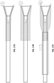
- FIGS. 1A-1C Previously described mechanical inverting tube apparatuses (also referred to as “mechanical thrombectomy apparatuses”) were configured to remove clot effectively, as shown in FIGS. 1A-1C .
- the apparatuses and methods of using them described herein may particularly effective for use with the peripheral vasculature, including for use with relatively larger outer diameter clots (e.g., relative to the maximum inner diameter of the inversion support catheter into which the clot is pulled).
- FIG. 1A illustrates an example of an inverting tractor mechanical thrombectomy apparatus 100 (such as described in U.S. patent application no. 15/496,570 , published as US 2017/0303948 A1 , and U.S. patent application no. 15/043,996 , published as US9463035 B1 .
- the inverting tractor mechanical thrombectomy apparatus 100 is shown deployed near a clot 109.
- the puller 101 (shown here as a puller micro catheter, alternatively the puller may be a wire) is held within an elongate inversion support catheter 107 so that the flexile tractor tube 103 extends from the end of the puller 101 and expands toward the inner radius of the elongate inversion support catheter 107; at the distal end opening 111 of the elongate inversion support catheter the tractor tube inverts over itself and extends proximally in an inverted configuration over the distal end of the elongate inversion support catheter.
- the puller 101 shown here as a puller micro catheter, alternatively the puller may be a wire
- the flexile tractor tube 103 extends from the end of the puller 101 and expands toward the inner radius of the elongate inversion support catheter 107
- the tractor tube inverts over itself and extends proximally in an inverted configuration over the distal end
- the elongate inversion support catheter is an elongate tube having a distal end that has the same size inner diameter as the proximal length of the inversion support catheter.
- the inversion support catheter 107 is shown positioned between the tractor tube (e.g., flexible tube 103) and the puller 101 so that the tractor tube can be pulled proximally by pulling on the puller and rolling the tractor tube into the elongate inversion support catheter so that it inverts.
- the portion of the tractor tube that is inverted over the distal end of the elongate inversion support catheter has an outer diameter that is greater than the outer diameter of the elongate inversion support catheter.
- the tractor may be biased so that it has a relaxed expanded configuration with a diameter that is greater than the outer diameter (OD) of the elongate inversion support catheter; in addition, the tractor tube may also be configured (e.g., by heat setting, etc.) so that when the tractor tube is everted and rolled over the distal end opening into the elongate inversion support catheter, the outer diameter of the tractor tube within the elongate inversion support catheter has an outer diameter that is about y times the inner diameter of the elongate inversion support catheter (e.g., where y is greater than 0.1x, 0.5x 0.6x, 0.7x, 0.75x, 0.8x, 0.9x, 1x, etc. the inner diameter, ID, of the elongate inversion support catheter.
- the tractor may be expandable and may be coupled to the puller as shown.
- the flexible tractor and the puller may comprise the same material but the tractor may be more flexible and/or expandable, or may be connected to elongate puller (e.g., a push/pull wire or catheter).
- the clot may be drawn into the elongate inversion support catheter by pulling the tractor proximally into the distal end of the elongate inversion support catheter, as indicated by the arrows 113, 113' showing pulling of the inner portion of the flexible tractor, resulting in rolling the tractor over the end opening of the catheter and into the catheter distal end and inverting the expandable distal end region so that it is pulled into the catheter, shown by arrows.
- the end of the tractor outside of the catheter may be "loose" relative to the outer wall of the catheter.
- FIG. 2 illustrate an example of an inverting tube apparatus 201 similar the one shown in in FIG. 1A .
- the inverting tube apparatus is in a large vessel that has a clot with a diameter that is greater than 2x the inner diameter of the inversion support catheter.
- the efficiency of the inversion may be low, e.g., requiring a flexible tube having approximately 12x the length of the clot tube to capture the entire clot.
- This figure illustrates the problem addressed by the apparatuses described herein; specifically, how to efficiently ingest long and large diameters clots (e.g., greater than 10 mm) into relatively smaller diameter inverting tube apparatuses.
- the 10 mm or larger diameter clot may be pulled into a 3 mm diameter (e.g., 8 French) inversion support catheter of the inverting tube apparatus
- the efficiency is low, because the length of the flexible tube that must be used to capture the entire length of the clot is extremely high.
- a 1 cm long clot having a diameter of 10 mm would require 12 cm of flexible tube when inverted and pulled into a 3 mm catheter; thus a clot that is 5 cm long would require 60 cm of flexible tube.
- the inverting tube apparatuses described herein may address and improve this efficiency in a number of ways.
- the inverting tube apparatuses described herein may dehydrate the clot as it is drawn into the inverting tube apparatus.
- Clots including even hard or partially calcified clots, may include a large amount of fluid that may be compressed and removed by the inverting tube apparatuses described herein.
- the flexible tube is typically porous, and may be, for example, a knitted material.
- the distal end region of the inversion support tube may be configured, particularly at the distal end region (e.g., the distal 5 mm, distal 4 mm, distal 3 mm, distal 2 mm, distal 1 mm, distal 0.9 mm, distal 0.8 mm, distal 0.75 mm, distal 0.7 mm, distal 0.6 mm, distal 0.5 mm, distal 0.4 mm, etc.) may be porous to allow fluid to escape laterally out of the inversion support catheter from the clot as the clot is drawn into the elongate inversion support catheter, so that the clot may compress more efficiently, rather than elongate or stretching.
- the distal end region e.g., the distal 5 mm, distal 4 mm, distal 3 mm, distal 2 mm, distal 1 mm, distal 0.9 mm, distal 0.8 mm, distal 0.75 mm, distal 0.7 mm, distal 0.6 mm, distal
- apparatuses that include a funnel-shaped distal end on the inversion support catheter that may be porous (particularly at the region near the base of the funnel) to allow compression of the clot material and ejection/removal of fluid from the clot laterally out of the sides of the inversion support catheter as clot is drawn proximally into the inversion support catheter by the rolling of the flexible tube (e.g., tractor).
- the funnel may be expandable (also referred to herein as collapsible) and may be integral with or attached to the distal end of the inversion support catheter.
- the funnel may be collapsed and introduced through a sheath/guide catheter (e.g., an intermediate catheter), so that it may fit, in a collapsed state, into a 6 French (2mm), 8 French (2,68 mm), 10 French (3,3 mm), 12 French (4mm), 14 French (4,6 mm), 16 French (5,4 mm), 28 French (9,24 mm), 20 French 6,66m), and/or 24 (7,92 mm)French sheath.
- the expandable funnel may be self-expanding.
- the expandable funnel at the distal end of the inversion support catheter may be expanded by actuation of the flexile tube; e.g., pulling the flexible tube into the inversion support catheter proximally to roll the flexible tube over the distal end of the inversion support catheter may apply a proximally-directed compressive force that pulls and expands the expandable funnel.
- the funnel may have a maximum outer diameter that is greater than 2x (e.g., greater than 2.5x, greater than 3x, greater than 3.5x greater than 4x, greater than 4.5x, greater than 5x, etc.) the maximum outer dimeter of the collapsed configuration; the maximum outer diameter of the funnel in the collapsed configuration may be approximately the same as, or slightly larger than, the maximum outer diameter of the body region of the inversion support catheter (e.g., 1x, 1.01x, 1.1x, 1.2x, etc. the outer diameter of the proximal portion of the inversion support catheter). In some variations the funnel has an outer diameter of between 2-26 mm.
- the flexible tube may also be adapted to better engulf and compress large-diameter clots.
- the flexile tube in the un-inverted configuration when outside of the inversion support catheter e.g., in the vessel
- the expandable funnel may allow the flexible tube (e.g., woven tractor) to grab clot at edges of cross section rather than the center of clot, which may enable a more efficient clot ingestion.
- flexible tube e.g., woven tractor
- the expanded non-inverted outer diameter of the flexible tube e.g., the portion of the flexible tube on the outside of the inversion support catheter prior to being pulled into the catheter and inverted
- a larger diameter (OD) than the maximum outer diameter of the expanded funnel, and preferably as large as possible with respect to the clot OD.
- Larger OD flexible tube may have higher efficiency for grabbing and compressing clot. This may be independent of whether there is a funnel on the distal end of the inversion support catheter.
- the OD of the un-inverted flexible tube may be selected to be at least 1/3rd of the clot OD (or vessel ID), for example, the expanded, un-inverted flexible tube may have an OD that is greater than or equal to about 50%, 60%, 70%, 80%, 90%, 100% or 110% of the clot OD (or vessel ID).
- the distal end of the inversion support catheter may be porous.
- the ability to allow fluid from compressed clot to exit from out of the sidewalls of the funnel inner diameter may provide a place for the fluid removed from the clot to go and may improve the efficiency of the apparatus, allowing for much shorter flexible tubes to remove a comparable length of clot. If the clot is not allowed to escape laterally (e.g., when using a non-porous funnel), the fluid removed may build up at the base of the funnel and may reduce the clot efficiency.
- the funnel is porous or at least partially porous, e.g., near the base of the funnel, where the compressive ratios of the clot are the highest.
- the inversion support catheter may be relatively large, so that the clot does not have to be compressed as much.
- the inversion support catheter may have an outer diameter that is greater than 1 mm, e.g., greater than 1 mm, 1.2 mm, 1.4 mm, 1.5 mm, 2 mm, 2.5 mm, 3 mm, 3.5 mm, 4 mm, 4.5 mm, 5 mm, etc.
- any of the apparatuses described herein may also increase the efficiency of the apparatus for removing clot by reducing the force need to remove the clot.
- the methods and apparatuses described herein may include a lubricious material on the distal end (e.g., the funnel) of the inversion support catheter.
- the funnel may be lined with a slippery material (e.g., a PTFE liner) that may produce a lower ingestion pull force and/or may reduce the ingesting efficiency.
- Slippery funnels may allow a clot mass to be drawn into the mouth of funnel rather than pulling it into the catheter.
- the funnel may be configured to have a specific shape (e.g., taper) that may also assist in increasing the efficiency for compressing and/or dehydrating the clot and may help reduce the amount of force required.
- a specific shape e.g., taper
- longer funnels may have a lower ingesting forces and better clot ingesting efficiency compared to shorter funnels of the same maximum OD/minimum ID.
- Examples of funnels may have a maximum OD of, e.g., 3 mm, 5 mm, 6 mm, 8 mm, 10 mm, 12 mm, 15 mm, 20 mm, 25 mm, etc.
- Exemplary funnel lengths may be, for example, 5 cm, 10 cm, 15 cm, 20 cm, 25 cm, 30 cm, 40 cm, 50 cm, 50 cm, 100 cm, etc.
- the body portion of the elongate flexible inversion catheter may be, e.g., a 3 French (F) (1mm), 4 F (1,32 mm), 5 F (1,5 mm), 6 F (1,98 mm), 7 F (2,31 mm), 8 F (2,64 mm), 9 F (2,97 mm), 10 F (3,3 mm), 11 F (3,63mm), 12 F (3,96 mm), 14 F (4,62 mm), 16 F (5,28 mm), 18 F (5,94 mm), 20 F (6,6 mm), 25 F (8,25 mm), etc. catheter.
- F French
- the flexible tube comprises a woven material
- coarser weaves may have increased efficiency.
- a larger number of weave "fingers" e.g., loops
- the number of grabbing fingers may be at least 10, 20, 20, 40, 50, 60, 100, etc., per tubular weave circumference.
- the inverting tube apparatuses described herein may be highly flexible, both before actuating and during operation.
- the flexible tube e.g., tractor
- the flexible tube may not significantly increase the stiffness/flexibility of the catheter of the elongate inversion support, and particularly the distal end region of the catheter, to avoid impacting maneuverability.
- Described herein are flexible tractor tube portions that increase the stiffness of the last y cm (e.g., distal most 20 cm, 18 cm, 15 cm, 12 cm, 10 cm, 9 cm, 8 cm, 7 cm, 6 cm, 5 cm, 4 cm, 3 cm, 2 cm, 1 cm, etc.) of the catheter less than a predetermined percentage (e.g., less than 10%, 12%, 15%, 18%, 20%, 25%, 30%, etc.).
- a predetermined percentage e.g., less than 10%, 12%, 15%, 18%, 20%, 25%, 30%, etc.
- the flexible tube (e.g., tractors) may be woven, braided and/or knitted materials.
- woven and braided materials which may include a plurality of fibers that are woven or braided to form the inverting tube, these structures may be tuned to prevent jamming and/or to reduce the force necessary to pull the tractor and invert over the catheter tip.
- the mechanical atherectomy apparatus may include a knitted or braided flexible tubes that can roll freely around the tip of catheter even in a tortuous anatomy and when grabbing clot by tuning one or more of the braid structure; minimizing the braid angle; including a hydrophilic coating on the distal aspect of the catheter outer diameter (OD) or the inner diameter (ID) of the braid (e.g., tractor); including a radiused wall on the catheter; and/or increasing the stiffness of the distal tip region relative to adjacent proximal regions.
- the flexible tube e.g., tractor
- the flexible tube may be braided, woven, knitted, etc., and may be configured to collapse down into the inner diameter (ID) of the catheter as little as possible.
- the tractor may collapse to an ID that is greater than, equal to, or within 90%, 85%, 75%, 70%, 65%, 60%, or 50% of the catheter inner diameter (ID)/Catheter Tip OD, since, where this ID is based on the elongate body region of the inversion support catheter, when the tractor is being pulled around catheter tip it may create axial tension on the tractor (e.g., braid, knit, etc.) that may otherwise inadvertently and undesirably cause the tractor to jam on the catheter tip.
- the tractor When tractor is pulled around catheter tip, the tractor may be pulled in the axial orientation creating axial tension on tractor structure as the tractor is being pulled through the catheter ID.
- the tractor elements jam at an ID greater than or equal to 90%, 85%, 75%, 70%, 65%, 60%, or 50% of the catheter ID (or in some variations, OD), when being axially tensioned, the tractor is less likely to grab/synch down onto the catheter tip, helping the braid roll around the catheter tip with less axial force applied by the user. If less axial force is required by the user to pull the tractor structure around the tip then the catheter tip is less likely to buckle or deflect when retracting the tractor. It may be advantageous to minimize the chance the catheter tip will buckle.
- the tractor can be tuned to "jam" at a specific ID by controlling any of the following variables and in any combination: selecting a specific number of braid ends, selecting the size/diameter of the braid ends; selecting the braid material (e.g., multifilament or monofilament); heat setting the bias on the braid (e.g., braid diameter); and selecting a braid pattern, e.g., 1 ⁇ 2, 1 ⁇ 1 or any other pattern.
- selecting a specific number of braid ends selecting the size/diameter of the braid ends
- selecting the braid material e.g., multifilament or monofilament
- heat setting the bias on the braid e.g., braid diameter
- selecting a braid pattern e.g., 1 ⁇ 2, 1 ⁇ 1 or any other pattern.
- the braid angle may be minimized to prevent locking up of the rolling of the tractor over the catheter end opening.
- the lower the braid angle e.g., 45 degrees or less, 40 degrees or less, 35 degrees or less, 30 degrees or less, 25 degrees or less, 20 degrees or less, etc. the less likely it is to have the braid cross over points catch on the catheter tip.
- the catheter and/or a surface of the tractor may be coated to enhance rolling over the distal end region of the catheter. It may be helpful to have a hydrophilic coating on the distal aspect of the catheter OD or the ID of the tractor so the tractor can more easily side over the catheters distal end and around the tip of the catheter when pulled through the inside of the catheter.
- the stiffness of the distal of the elongate inversion support catheter may be sufficiently stiff to prevent collapse as the tractor is pulled; it may also be lubricious (e.g., by a coating or material property).
- the distal most section of the elongate inversion support catheter tip e.g., the last 5 mm
- the distal most section of the elongate inversion support catheter tip may be fabricated of a material which is stiff enough and lubricious enough so the distal tip of the catheter does not collapse or buckle inward when the braid structure is rolling around the catheter tip.
- the distal tip may have a stiffness that is greater than the more proximal region at the distal end of the catheter.
- FIGS. 3A-3B and 4A-4B illustrate examples of inverting tube apparatuses that each include a funnel region at the distal end of an inversion support catheter.
- FIG. 3A shows a first variations of an inverting tube apparatus 300 that includes an elongate, flexible inversion support catheter 307 that has an expandable funnel 308 at the distal end, shown in a collapsed configuration in FIG. 3A within an intermediate (e.g., delivery) catheter 309, and in an expanded configuration in FIG. 3B after being released from the intermediate catheter.
- the funnel may be formed of a woven material and may be porous, particularly at the base region 313, where the funnel extend from the body of the elongate body of the inversion support catheter.
- a flexible tube 305 extends over the distal end (including the funnel) of the inversion support catheter and inverts over the distal opening of the funnel.
- the flexible tube may be, e.g., a knitted material, and may be biased to expand to an outer diameter (OD) that is larger than the OD of the funnel 308 in the expanded configuration.
- the flexible tube is attached to a distal end region of a puller 303. In the example shown in FIGS. 3A-3B the puller extends distally 315 further than the distal end of the funnel, as shown.
- the flexible tube e.g., tractor
- the end of the flexible tube in this example is attached proximally of the distal end of the device.
- FIG. 4A shows the inverting tube apparatus 400 within an intermediate catheter (e.g., deliver catheter) 409 with a funnel 408 at the distal end of the inversion support catheter 407 within the intermediate catheter in a collapsed configuration.
- the funnel may include one or more (e.g., a plurality of circumferentially-arranged) openings or pores at the base 413 region to permit fluid from the clot to exit the inversion support catheter as the clot is pulled into the inversion support catheter by the rolling flexible tube 405 (e.g., tractor region).
- FIG. 4B shows the apparatus at least partially deployed from out of the intermediate catheter 409, with the expandable funnel 408 expanded.
- FIG. 4C is a picture of a prototype apparatus 400' in which the inversion support catheter 407' includes an expandable funnel 408' (shown expanded) and over which a flexible tube 405' may roll and invert to capture clot material when used as a thrombectomy device.
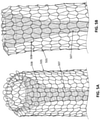
- the flexible tube is shown as a knitted tube, forming a plurality (e.g., > 15) of loops or fingers at the distal-facing end of the apparatus, which may help capture clot material. This is shown in more detail in FIGS. 5A and 5B .
- a porous funnel 508 forming the distal end of an inversion support catheter 507 is shown with a knitted flexible tube 505 shown inverting over and into the funnel when the flexible tube is pulled proximally into the funnel.
- the expandable funnel may be formed of a woven and/or braided material, as shown in FIGS 6A-6D .
- the funnel is configured to handle a relatively large compressive load as may be necessary to compress and/or dehydrate a large-diameter clot when drawing the clot into the device.
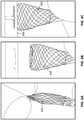
- the funnel 608 is shown collapsed; the funnel can collapse to a smaller OD to enable introduction through small ID sheath, for example by elongating the funnel shape, as shown.
- the funnel may be self-expanded, as shown in FIG. 6B to a fully or partially expanded configuration, e.g., when released from a delivery catheter within the vessel.
- the funnel may further expanded (more fully) when pressed into a clot or against a body 609, as shown in FIG. 6C , resulting in a compressive force 611 being applied in the proximal direction on the funnel, jamming it into a higher-strength configuration, as will be shown in greater detail in FIG. 12 , below.
- FIG. 6D shows a distal perspective view of a funnel end of an inversion support catheter with a knitted tractor (knitted flexible tube) 603 inverting into the funnel.
- the funnel flares outward from a 5 mm ID to an 8 mm ID in the expanded configuration.
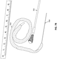
- FIGS. 7A and 7B illustrate an example of an inverting tube apparatus with a flexible tube (e.g., knitted tractor tube 703) and an inversion support tube 705 including an expandable funnel 708 ingesting a clot 711.
- FIG. 7A shows the clot and apparatus before ingesting.
- FIG. 7B shows the clot within the flexible tube after ingestion into the inversion support catheter, after the flexible tube has been removed from within the inversion support tube (the woven flexible tube is shown attached to a puller 709).
- FIGS. 7A and 7A illustrate an example of an inverting tube apparatus with a flexible tube (e.g., knitted tractor tube 703) and an inversion support tube 705 including an expandable funnel 708 ingesting a clot 711.
- FIG. 7A shows the clot and apparatus before ingesting.
- FIG. 7B shows the clot within the flexible tube after ingestion into the inversion support catheter, after the flexible tube has been removed from within the in
- FIG. 8A-8B illustrate another example of an inverting tube apparatus 800, shown with a non-funnel tipped inversion support catheter 807 has been heat set so that the woven flexible tube (tractor tube) has an outer diameter approximately equal to the OD of the clot 811, resulting in a relatively high clot efficiency, as shown in FIG. 8B , showing the captured clot 811' after removal from the apparatus.
- FIG. 9A shows an example of an inverting tube apparatus (thrombecomy apparatus) 900 that includes an inversion support catheter 907 and a woven flexible tube 905.
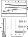
- FIG. 9B is a graph showing the length (in cm) of the knitted flexible tube (tractor tube) of the apparatus needed to fully capture a 5 cm length of clot having an outer diameter of 15 mm. As shown the larger the outer diameter of the flexible tube in the un-inverted, expanded configuration, e.g., on the outside of the inversion support catheter, the smaller the length of knitted flexible tube needed.
- FIG. 9C illustrates examples of various inverting tube apparatuses, showing exemplary dimensions.
- FIGS. 10A-10C illustrate different variations of funnel-shaped distal ends.
- the funnel 1013 is shown and may be solid or may include openings for allowing the passage of fluid (e.g., may be porous), including porous over its entire surface.
- FIG. 10B shows an example in which only a portion of the expandable funnel is porous.
- the base region 1023 is porous, and includes a plurality of openings arranged circumferentially around the perimeter of the base region of the funnel 1013.
- the expandable funnel 1013 variation shown in FIG. 10C is porous over its entire length, and is shown formed of a woven material (e.g., a metal or polymeric fiber) that may be doubled back over itself to form the funnel-shape.
- FIG. 10D shows a cross-section through the variation of FIG. 10C , showing attachment 1021 of the tubular weave forming the funnel to the outside of the body region of the elongate, flexible inversion support catheter 1007 and at a second end 1025 of a portion of the funnel within the mouth of the funnel.
- Any of these variations may include a lubricious sleeve (e.g., a Teflon sleeve).
- FIGS. 11A-11D illustrate one example of a distal end of an inversion support catheter including a funnel.
- the funnel is formed integrally with the body of the inversion support catheter.
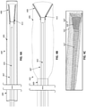
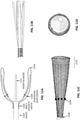
- the funnel shape includes a framework formed by a plurality of fingers or struts 1111 formed by cutting (e.g. laser cutting) the distal end of the body of the inversion support catheter 1107.
- a braided or woven funnel body 1118 is attached to the struts; the woven body is attached 1105 to the body of the inversion support catheter on one end, and on the other end 1109 to lock it in place over the struts.
- FIG. 11B shows an example of a body of an elongate support catheter that has been cut into a plurality of struts or fingers over which the funnel body may be supported, as shown in FIG. 11C .
- the distal end of the funnel 1131 is opened and may extend beyond the struts and may jam to form a locked open configuration having a high compression strength, even in the absence of the underlying struts or fingers.
- FIG. 11D shows an example of an open distal end of the funnel of the apparatus.
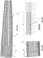
- FIG. 12 is an enlarged version of the distal end of the funnel shown in FIG. 11C , illustrating the application of axial compression that may cause the distal end of the apparatus to 'jam' and from a larger braid angle ( ⁇ ) at the distal end, compared to the unjammed more proximal end. This compressive force may help open (and hold open) the expandable funnel.
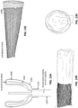
- FIGS. 13A-13D show another variations of a funnel portion of an inversion support catheter, including a lubricious sleeve (e.g. Teflon sleeve).
- a schematic of the funnel shows that it may be formed of a plurality of arms 1303 and a braided funnel body 1305 may be bonded over the arms (similar to the variation shown in FIGS. 11A-11D ) formed from the body of the inversion support catheter 1307.
- the braided body may be bonded to the catheter body 1316.
- a Teflon sleeve 1309 may be attached at one or more locations along the OD of the braided body region, as shown.
- the Teflon sleeve does not cover the base region, allowing fluid to exit the funnel laterally near the base of the funnel.
- FIG. 13B is a side view of a prototype of the inversion support catheter of FIG. 13A shown in a side perspective view in a collapsed (non-expanded) configuration.
- FIG. 13C shows the funnel in the expanded configuration.
- the Teflon sleeve 1309 is shown attached on the outside of the expanded funnel, partially down the length of the funnel.
- FIG. 13D shows an end view of the distal end of the funnel of the inversion support catheter of FIGS. 13B-13C .
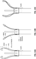
- FIGS. 14A-14C illustrate different examples of lubricious sleeves that may be included with any of the apparatuses shown.
- a Teflon sleeve (PTFE tube) is attached within the mouth of the funnel and can be attached at the distal end but allowed to float at the proximal end.
- the lubricous sleeve (PTFE sleeve) is attached under the woven body forming the funnel shape, and may be bonded at the proximal end or allowed to float.
- the lubricous sleeve is attached on the outside and inverts over the distal end of the funnel shape, and is allowed to float proximally (or may be attached proximally).
- FIGS. 15A and 15B illustrate other variation of inversions support catheters including funnels.
- the funnel is formed of a set of laser-cut fingers cut and formed into a funnel; a funnel body material may be attached within the inside of the funnel shape and/or over these shapes, as described above.
- the end of the catheter body may be laser cut into a plurality of curving arms that may form a funnel-shape.
- FIGS. 16A-16D show four variations of inverting tube apparatuses that may be used.
- a 5 French (1,65 mm) apparatus is shown, which does not include a funnel on the distal end of the inversion support catheter.
- FIG. 16B show an example (sized for a 6F (1,98 mm) system) that does include an inversion support catheter having an expandable funnel.
- FIGS. 16C and 16D illustrate 8F and 10F apparatuses, respectively.
- FIGS. 17A-17C illustrate variations in which the flexible tube is configured to have an expanded (e.g. non-compressed) configuration that is narrow ( FIG. 17A ), e.g., less than the maximum OD of the expanded funnel, or broad ( FIGS. 17B and 17C ), e.g., larger than the maximum OD of the expanded funnel.
- the delivery catheter 1705 may be used to drive the flexible tube distally (e.g., to prevent tension) when rolling the flexible tube over the funnel at the distal end of the inversion support catheter by pulling the first end of the flexible tube proximally within the inversion support catheter.
- the inverting tube apparatus includes the flexible tube and inversion support catheter (e.g., with an expandable funnel at the distal end) and may also include one or more ring cutters for cutting into and/or around atheroma within a vessel.
- FIG. 18A illustrates an example of an inverting tube apparatus including a pair of ring cutters (e.g., a MollRing Cutter) that may be used to cut laterally through an atheroma. The ring cutters may pass over the outside of the inversion support catheter.
- the rolling, inverting flexible tube in some variations may be formed of a sharp or cutting material, such as a sheet of laser-cut material (e.g., metal, polymeric, etc.) that is cut at an angle relative to the perpendicular, so as to have a sharp edge that may engage and cut calcified material and/or tissue.
- the cutting rings may further allow cutting into and through a dense plaque material.
- any of the inversion support catheters described herein that include an expandable/collapsible funnel at their distal end may be configured to collapse to a small diameter for easy insertion into a catheter and/or sheath, including when a flexible tube (e.g., tractor) is preloaded around the funnel.
- a tool such as an introducer sheath may be used to hold the distal end (e.g., the funnel) of the inversion support catheter, with or without a flexible tube attached, in a collapsed form so that it may be easily inserted into a lumen of a delivery catheter that may already be positioned within the body or that may be loaded into the body with the inversion support catheter and flexible tube assembly inserted.
- Collapsing the funnel at the distal end into a smaller diameter may help thread the "loaded" inversion support catheter into the delivery catheter and therefore into the body.
- a tool such as an introducer sheath
- the introducer sheath may be a polymeric (e.g., plastic) tapered tube with a slit, perforation or tear-away region extending along the length.
- the funnel may be collapsed and inserted into the wider end of the introducer sheath and the inversion support catheter may be pushed to slide distally within the introducer sheath towards the narrower end.
- the narrow end may then be loaded into the delivery catheter and the inversion support catheter may be pushed distally out of the introducer sheath and into the delivery catheter; the introducer sheath may then be torn down its length (e.g., along the pre-formed tear line) to remove it from around the inversion support catheter.
- An example of an introducer sheath is shown in FIG. 25 , described in greater detail below.
- the funnel portion of an inversion support catheter may be configured to collapse, at least the distal end region, down to less than the diameter of the rest of the inversion support catheter, e.g., the region proximal to the funnel.
- the funnel may be configured to collapse down to fit into a 3F (1mm), 4 F (1,32 mm), 5 F (1,5 mm), 6 F (1,98 mm), 7 F (2,31 mm), 8 F (2,64 mm), 9 F (2,97 mm), 10 F (3,3 mm), 11 F (3,63mm), 12 F (3,96 mm), 14 F (4,62 mm), 16 F (5,28 mm), 18 F (5,94 mm), 20 F (6,6 mm), 24F (7,92mm), 30F (9,9 mm), etc. sheath or guide catheter (also referred to herein as a delivery catheter).
- the funnel portion of the inversion support catheter may be adapted for this purpose in a variety of ways, including, but not limited to, the features of the components forming the funnel portion.
- the outer and inner surfaces of the funnel portion may be formed of a mesh material, such as a braid.
- the specific mesh or braid structure may contribute to the amount that the funnel can collapse, such as the number of number of filaments forming the braid (e.g., the number of ends), the size of the filaments (e.g., the size of ends), the braid angle, etc.
- the ability of the funnel portion to collapse may be determined in part by the ability of the tines to move within the inner and outer surfaces (e.g., of the mesh or woven material forming the walls of the funnel).
- a braided tube forming the funnel wall may slide relative to the tines to allow the funnel to collapse to small diameter for introduction.
- FIG. 19 shows a portion of one example of an inversion support catheter having a funnel at the distal end.
- the funnel may be formed in part by a plurality of tines 1905 extending from the distal end of the inversion support catheter.
- the distal end region of the inversion support catheter may be formed of a metallic hypotube that is cut, e.g., by laser cutting laterally, to form tines.
- FIG. 19 six tines are shown.
- the tines may be flared outward from each other, e.g., on a mandrel (as shown in FIG. 20A ).
- the tines may be formed by folding the cut 'arms' back on themselves so that the distal ends 1909 are blunted or rounded, as shown in FIG.
- the folded over portion of the tine 1907 may be folded inward and crimped together, as shown.
- a filament may be included to radially connect each tine of the plurality of tines. This is illustrated in FIG. 20A and 20B .
- the filament 2007 is a suture that is threaded at the distal ends of the tines 2005 (where they are folded back on themselves). Typically the filament is attached at or near the distal end (e.g., within 1 mm, 2 mm, 3 mm, 4 mm, etc. from the distal end) of the tines.
- Each of the tines 2005 shown is connected to a radially adjacent tine by a filament 2007. Connecting the tines to each other along their length, including at their distal ends, may help distribute the forces that may otherwise cause a tine to collapse and/or bend, impairing the function of the inversion support catheter.
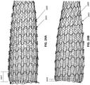
- FIGS. 21A and 21B illustrate an example of a mesh material that may be used to form the outer and inner surfaces (e.g., the wall) of the funnel.
- a tube of mesh (e.g., woven) material 2100 is shown in FIG. 21A , which has been inverted back over itself as shown, forming an inner 2103 and outer 2104 surfaces.
- the material (e.g., braid) forming the walls may be shape set (e.g., heat set) into this double layer.
- the material may be shape set so that, in the jammed configuration, the inner layer has a smaller outer diameter (OD) than the outer layer's inner diameter (ID), which may create a space for the tines to slide.
- OD outer diameter
- ID inner diameter
- FIG. 21 B shows an enlarged view of a portion of the braided wall material of FIG. 21A .
- the braided material is shown as braids of flat wire; round and/or flat cross-sectional wire may be used to form the braided material.
- the braid angle may be selected to allow compression of the funnel as well as setting the jamming configuration, at which the funnel is maximally expanded.
- FIGS. 22A-22C illustrate a funnel 2200 formed by applying the braided wall material, such as shown in FIG. 21A onto the tines at the distal end of the inversion support catheter, such as shown in the example of FIG. 19 .
- the inner and outer walls of the woven material forming the funnel are stitched together by a suture 2221 that is arranged radially around the funnel and may constrain it from expanding further, as described above.
- the tines may slide axially relative to the inner and outer walls.
- the mesh material forming the inner and outer walls may extend distally further than the distal end of the tines. In the relaxed configuration, shown in FIG.
- FIG. 22A shows the braid length distal to the distal ends of the tines 2214 as a distance x 1 mm.
- FIG. 22B shows the funnel with the braid jammed 2213, as it would be if the tractor (e.g., the flexible tube) were loaded over the funnel and pulled proximally into the inversion support catheter. In this configuration the axial length of the braided wall extending beyond the tip of the tines as x 2 mm.
- FIG. 22C shows the collapsed (and loaded into an introducer sheath 2217) so that the axial length of the braided wall extending beyond the tip of the tines is x 3 mm.
- FIG. 23 shows another example of an inversion catheter including a funnel as described above.
- the funnel 2300 includes a suture 2413 (e.g., a restraining filament) integrated between inner and outer layers (e.g., walls) of funnel to prevent relative sliding of the inner and outer braid layer, so the braid jams at the tip, while allowing sliding of the tines 2318 between the inner and outer braided material walls.
- the suture limits the diameter 2305, 2307 of the funnel in the expanded configurations, as shown.
- the outer diameter of the funnel at various positions along the length of the funnel may be limited or set by the use of a restraining filament, such as a suture, wire, etc.
- the restraining filament(s) may be referred to herein as circumferential supports extending radially around the funnel surface and constraining the maximum outer diameter of the expandable funnel.
- the restraining filament may be held in place by stitching it into the mesh (e.g., woven) material forming the funnel wall(s).
- the filament may constrain the OD of the funnel to a desired diameter/profile.
- each of these funnels includes a porous structure to enable clot or tissue to be partially desiccated when pulled into through base of funnel, by allowing fluids to ooze out through the side of the funnel.
- the funnels described herein may have a smooth transition from the funnel ID to the catheter ID. This may be achieved by laser cutting the tines at the distal of the catheter, as shown.
- the porous structure and/or the smooth transition may also be provided in these examples by the porous metallic mesh (e.g., braid) structure forming the walls.
- the inversion support catheters described and illustrated herein may be adapted to prevent collapse, even when force is applied by the flexible tube either without or with a clot material.
- the funnel needs to be able to handle axial loads (e.g., loads applied along axis of catheter shaft length) that may be in excess of 1, 2, 3, 4, 5, 10, 15 and/or 20 kg, without collapsing, e.g., when there is resistance ingesting the clot, while still allowing the flexible tube (e.g., tractor) to roll around the top of the funnel and into the inversion support catheter.
- Axial stiffness may be achieved at least in part by configuring the braided wall of the funnel have a jammed configuration at tip as described above.
- Axial stiffness may also be improved by limiting the length of the braided wall extending beyond the distal tips of the tines in the jammed configuration (e.g., to 5 mm or less).
- axial stiffness may also be improved by including the circumferential support (e.g., filament) between the tines, as described above, which may distribute the load exerted from the tractor on the funnel tip, so that the funnel tips stays round and no one finger gets isolated and collapses.
- the end of the funnel may also preferably be sufficiently stiff to prevent the funnel from collapsing radially when the tractor rolls around the tip.
- Radial stiffness of funnel may be achieved at least in part by configuring the braided wall of the funnel have a jammed configuration at tip as described above. Radial stiffness may also be improved by limiting the length of the braided wall extending beyond the distal tips of the tines in the jammed configuration (e.g., to 5 mm or less).
- radial stiffness may also be improved by including the circumferential support (e.g., filament) between the tines, as described above, which may distribute the load exerted from the tractor on the funnel tip, so that the funnel tips stays round and no one finger gets isolated and collapses.
- circumferential support e.g., filament
- the funnel may be configured so that it only fully expands when the axial loads are applied, e.g., when pulling the flexible tube (e.g., tractor) proximally to roll into the inversion support catheter. This may allow the funnel to be advanced in smaller vessels before it is actuated.
- the flexible tube e.g., tractor
- FIG. 24A illustrates on example of an assembly including an inversion support catheter having a funnel as described above, with a flexible tube loaded onto and into the inversion support catheter so that the flexible tube (tractor) extends along the outside of the inversion support catheter and over the funnel before inverting into the interior of the funnel, as shown.
- the funnel 2405 is not fully expanded and the knit flexible tube 2403 is not being drawn into the inversion support catheter.
- FIG. 24B the flexible tube 2403 is pulled into the inversion support catheter so that it rolls into the catheter; in doing so, the flexible tube/tractor applies axial load and fully extends the funnel 2405 to a jammed configuration.
- the portion of the funnel wall extending beyond the tines 2407 in the relaxed configuration shown in FIG. 24A is greater than the length of the funnel wall extending beyond the tines 2409 in the jammed configuration shown in FIG. 24B .
- FIG. 25 shows one illustration of a systems for performing a thrombectomy that is packaged together.
- the system 2500 includes pre-loaded component such as an inversion support catheter 2512 that has been pre-loaded with a tractor (flexible tube); the assembly of the flexible tube and inversion support catheter is shown enclosed in a loading sheath 2503 (a spare loading sheath 2522 is also shown) for loading into a delivery catheter (not shown).
- pre-loaded component such as an inversion support catheter 2512 that has been pre-loaded with a tractor (flexible tube); the assembly of the flexible tube and inversion support catheter is shown enclosed in a loading sheath 2503 (a spare loading sheath 2522 is also shown) for loading into a delivery catheter (not shown).
- the assembly of the flexible tube and inversion support catheter is also proximally covered in a tear-away sleeve 2511 extending over the flexible tube and the inversion support catheter and configured to be removed from over the flexible tube by tearing along a length of the tear-away sleeve as the inversion support catheter and flexible tube are loaded into a delivery catheter.
- a pair of locks 2514 are also shown as part of the kit in FIG. 25 .
- a pair of additional tractors 2520 flexible tubes connected to a puller are also included. These additional flexible tubes may be loaded into the inversion support catheter after completely removing the pre-loaded tractor.
- an additional flexible tube may be loaded onto an inversion support catheter after the original inversion support catheter has been pulled through the lumen of the inversion support catheter, e.g., when removing a clot.
- the additional flexible tube may be attached to a puller and the puller and a portion of the additional flexible tube (e.g., the first portion) may be pulled through the distal end (funnel end) of the inversion support catheter while the second portion may be pulled over the outside of the inversion support catheter.
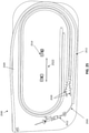
- any of the inversion support catheters 2601 described herein may include a stop 2607, as shown in FIG. 26 .
- the stop may prevent the proximal end of the tractor (flexible tube) 2603 from pushing proximally past the stop, e.g., when loading the assembly of the flexible tube and inversion support catheter into the delivery catheter, as described above, and/or when loading a flexible tube onto the inversion support catheter.
- the stop may engage with a cuff (e.g., an elastic cuff) 2609 on the end of the tractor.
- the tear-away sleeve may also help reduce or prevent this.
- FIGS. 27A and 27B illustrate an example of a lock 2701 that may be used to secure an inversion support catheter 2711 to a delivery catheter 2713 so that the two portions may be moved together.
- the lock may include an annular clamp 2703 for connecting to the outside of the inversion support catheter, as well as an L- or J- shaped lock 2705 for coupling to the end of the delivery catheter. By loosening or tightening the annular clamp, the inversion support catheter may be permitted to slide separately or coupled together with the delivery catheter.
Landscapes
- Health & Medical Sciences (AREA)
- Life Sciences & Earth Sciences (AREA)
- Surgery (AREA)
- Veterinary Medicine (AREA)
- Public Health (AREA)
- General Health & Medical Sciences (AREA)
- Engineering & Computer Science (AREA)
- Biomedical Technology (AREA)
- Heart & Thoracic Surgery (AREA)
- Animal Behavior & Ethology (AREA)
- Molecular Biology (AREA)
- Medical Informatics (AREA)
- Nuclear Medicine, Radiotherapy & Molecular Imaging (AREA)
- Vascular Medicine (AREA)
- Biophysics (AREA)
- Pulmonology (AREA)
- Anesthesiology (AREA)
- Hematology (AREA)
- Orthopedic Medicine & Surgery (AREA)
- Surgical Instruments (AREA)
- Media Introduction/Drainage Providing Device (AREA)
Description
- The apparatuses and exemplary methods not forming part of the invention described herein relate to mechanical removal of objects from within a body. In particular, described herein are mechanical thrombectomy apparatuses and methods.
- Many vascular problems stem from insufficient blood flow through blood vessels. One causes of insufficient or irregular blood flow is a blockage within a blood vessel referred to as a blood clot, or thrombus. Thrombi can occur for many reasons, including after a trauma such as surgery, or due to other causes. For example, a large percentage of the more than 1.2 million heart attacks in the United States are caused by blood clots (thrombi) which form within a coronary artery. It is often desirable to remove tissue from the body in a minimally invasive manner as possible, so as not to damage other tissues. For example, removal of tissue, such as blood clots, from within a patient's vasculature may improve patient conditions and quality of life.
- Mechanical thrombectomy devices may be particularly advantageous. There is a definite need for thrombectomy devices, and particularly for mechanical thrombectomy devices that can be easily and accurately delivered through the, often tortious, anatomy in the peripheral and central vasculature, then be reliably deployed to remove clot material. Further, there is a need for devices that are easy and intuitive to operate.
- Finally, there is a distinct need for mechanical thrombectomy apparatuses that may have a low profile, but can be inserted into a comparatively large-diameter vessel. Thus, described herein are apparatuses (devices, systems and kits) and methods of using them that may address the needs and problems discussed above.
- The publication
WO2017/189535 describes thrombectomy apparatuses comprising an inversion support catheter having an expandable funnel disposed at a distal end of the catheter body and a flexible tube inverting over the distal end of the funnel. This configuration assists capture of greater clots. - There is a need for an improved thrombectomy apparatus fo this kind which can capture such larger clots even if they are hard and partially calcified without clogging or breaking.
- The object of the invention is to satisfy such needs.
- Described herein are mechanical thrombectomy apparatuses (devices, systems, etc.) These apparatuses may also be referred to as inverting mechanical thrombectomy apparatuses and/or inverting tube thrombectomy apparatuses. In particular, described herein are inverting tube thrombectomy apparatuses that may be deployed within even very large vessels in order to efficiently ingest one or more large clots. For example, the apparatuses described herein may be configured to provide a high pulling efficiency in order to ingest and remove even long and large-diameter clots, e.g., greater than 10 mm length and/or greater than 5 mm diameter, in a catheter having a smaller or much smaller diameter (e.g., 5 mm, 4 mm, 3 mm, 2 mm, etc.) using a flexible tube (e.g., tractor tube). In some variations the flexible tube may be longer than 5x the length of the clot (e.g., alternatively requiring a tractor tube that is longer than 6x, 7x, 8x).
- Further properties of the invention are described and defined in the attached claims.
- The novel features of the invention are set forth in the claims that follow. A better understanding of the features and advantages of the present invention will be obtained by reference to the following detailed description that sets forth illustrative embodiments, in which the principles of the invention are utilized, and the accompanying drawings of which:
-
FIGS. 1A-1C illustrate an example of a mechanical inverting tube apparatus that is particularly well adapted for use in a small, and tortious vessel anatomy. InFIG. 1A , the assembled apparatus is shown in a side view, showing an inversion support catheter and a flexible outer tube.FIG. 1B shows the inverting tube apparatus ofFIG. 1A in a vessel, proximal to a clot.FIG. 1C illustrates the removal of a clot from the vessel using the apparatus ofFIG. 1A , by pulling the flexible tube on the outside of the inversion support catheter proximally so that it rolls over the distal end of the inversion support catheter and into the inversion support catheter, drawing the clot with it; the apparatus may be advanced distally. -
FIG. 2 is an example of an inverting tube apparatus similar the one shown in inFIG. 1A in a large vessel, having clot with a diameter that is greater than 2x the inner diameter of the inversion support catheter. Although the clot may be ingested and removed by the inverting tube apparatus having a narrower-diameter inversion support catheter, the efficiency of the inversion may be low, e.g., requiring a flexible tube having approximately 12x the length of the clot tube to capture the entire clot. -
FIGS. 3A-3B shows an example of an inverting tube apparatus adapted to dehydrate (e.g. remove liquid) from the clot as it is ingested, increasing the efficiency of the inversion. InFIG. 3A the inverting tube apparatus is shown in an undeployed stated, within an intermediate (e.g., delivery) catheter; the inversion support catheter includes an expandable funnel at the distal end over which a flexible tube inverts. The flexible tube is attached at a distal end region of the puller so that the puller may extend distally. InFIG. 3B the inverting tube apparatus ofFIG. 3A is shown in a deployed configuration with at least the distal end extending from the intermediate catheter; the expandable funnel at the distal end of the inversion support catheter is in an expanded configuration. -
FIGS. 4A-4B illustrate another example of an inverting tube apparatus including an expandable funnel, in which the flexible tube (e.g., knitted tube) is attached to distal end of a puller.FIG. 4B shows the inverting tube apparatus ofFIG. 4A in a deployed configuration with the intermediate (e.g., delivery) catheter withdrawn proximally so that the expandable funnel at the distal end of the inversion support catheter can expand, and the flexible tube can expand. -
FIG. 4C is an image of a prototype of an inverting tube apparatus similar to that shown inFIGS. 4A-4C . -
FIGS. 5A-5B show an example of the distal end of an inverting tube apparatus including a funnel at the distal end of the inversion support catheter, over which the knitted flexible tube rolls and inverts.FIG. 5A is a top perspective view andFIG. 5B is a side view. -
FIGS. 6A-6D illustrate one example of a prototype inversion support catheter including an expandable funnel at the distal end, which may be used with an inverting tube apparatus.FIG. 6A shows the expandable funnel in a collapsed form.FIG. 6B shows the expandable funnel deployed (e.g., from out of an intermediate or delivery catheter, not shown).FIG. 6C shows the expandable funnel fully deployed by applying a compressive force along the long axis of the inversion support tube.FIG. 6D shows an example of an inverting tube apparatus including the inversion support catheter having an expandable funnel as shown inFIGS. 6A-6C . -
FIG. 7A illustrates one example of an inverting tube apparatus configured to dehydrate a clot as it engulfs the clot. InFIG. 7A , the inverting tube apparatus is shown next to a 4 mm clot prior to ingesting the clot.FIG. 7B shows the inverting tube apparatus after it has engulfed the clot, with the flexible tube removed from the inversion support catheter having an expandable funnel. -
FIG. 8A illustrate an example of an inverting tube apparatus in which the flexible tube inner diameter has been selected to match the outer diameter of the clot before the inverting tube apparatus has ingested the clot.FIG. 8B shows the clot after it has been captured (ingested) by the flexible tube of the inverting tube apparatus. -
FIGS. 9A-9C illustrate the relationship between clot efficiency (e.g., the length of the flexible tube required to engulf and remove a clot), showing that the clot efficiency improves with larger outer diameter flexible tubes.FIG. 9A illustrates an example of an inverting tube apparatus engulfing a clot within a vessel.FIG. 9B is a graph showing the length of flexible tube (knitted flexible tube) required to ingest 5 cm of a clot having a 15 mm outer diameter (OD) into an inversion support catheter that is 8F (e.g., less than 2.67 mm) inner diameter (ID).FIG. 9C illustrates example of various inverting tube apparatuses having different flexible tube ODs. -
FIGS. 10A-10D illustrate examples of inversion support catheters with expandable funnels at their distal ends. -
FIG. 11A-11D illustrates an example of an inversion support catheter with an expandable funnel.FIG. 11A is a schematic illustration of an inversion support catheter including a funnel including a support frame that is formed from the distal end region of the elongate inversion support catheter.FIG. 11B shows an example of an inversion support catheter cut to form the supports shown schematically inFIG. 11A. FIG. 11C is an example of a distal funnel of an inversion support catheter formed by a braided material attached to a frame such as the frame shown inFIG. 11B. FIG. 11D is an end view of the funnel shown inFIG. 11C . -
FIG. 12 is an example of a funnel of an inversion support catheter that is configured to have an axial compressive strength that is sufficient to resist collapsing when greater than 500g (e.g., greater than 1 kg, greater than 1.2 kg, greater than 1.5 kg, etc.) of axial compressive force is applied. In this example, the axial compressive force, which may be applied by the flexible tube being drawn proximally (e.g., pulled) to roll over the distal end of the funnel, may also open the funnel to deploy it. -
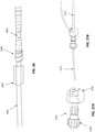
FIGS. 13A-13D illustrates an example of an inversion support catheter with an expandable funnel that is lined with a lubricious (e.g., Teflon) sleeve.FIG. 13A is a schematic illustration of an inversion support catheter including a funnel including a support frame that is formed from the distal end region of the elongate inversion support catheter and a lubricious sleeve.FIG. 13B shows an example of an inversion support catheter such as the one shown schematically inFIG. 13A , including a lubricious sleeve.FIG. 13C is an example of a distal funnel of an inversion support catheter such as the one shown inFIG. 13B in an expended configuration.FIG. 13D is an end view of the funnel shown inFIG. 13C . -
FIGS. 14A-14C illustrate examples of expandable funnels of inversion support catheters that may include lubricous sleeves within the mouth of the funnel to reduce the pulling force. -
FIG. 15A is an example of a frame cut to form a funnel at the distal end of an inversion support catheter; inFIG. 15A the fingers formed by cutting the distal end of the catheter are covered with a PTFE membrane in the mouth of the funnel. -
FIG. 15B is an example of a frame cut to form a funnel at the distal end of an inversion support catheter, having curved struts (fingers) forming the funnel region. -
FIGS. 16A-16D illustrate examples of thrombectomy devices having different sizes that may be selected by a user based on the vessel and/or clot size. -
FIGS. 17A-17C illustrate example of inverting tube apparatuses that may be used for removing an atheroma (e.g., atherectomy) -
FIGS. 18A-18C illustrate one exemplary method not forming part of the invention of removing an atheroma using an inverting tube apparatus and a pair of cutting rings. -
FIG. 19 shows one example of a portion of the distal end of an inversion support catheter including a plurality of tines. -
FIG. 20A is an example of a plurality of tines of an inversion support catheter having an expandable funnel that includes a filament connecting adjacent tines. -
FIG. 20B is an enlarged view of the distal end of a tine (showing the filament) ofFIG. 20A . -
FIG. 21A is an example of a flexible tube of woven material that may form the funnel surface of an expandable funnel of an inversion support catheter; the woven material is inverted over itself and shape (e.g., heat) set so that there is a space between the outer funnel surface and the inner funnel surface in which tines may fit. -
FIG. 21B shows an enlarged view of the flexible tube ofFIG. 21A . -
FIG. 22A is an example of an expandable funnel of an inversion support catheter in a relaxed state. -
FIG. 22B shows the expandable funnel ofFIG. 22A in a fully expanded configuration, with compressive stress applied. -
FIG. 22C shows the expandable funnel ofFIG. 22C collapsed and constrained in a loading sleeve. -
FIG. 23 is another example of an expandable funnel of an inversion support catheter. -
FIG. 24A shows an example of an expandable funnel of an inversion support catheter with a flexible tube of knitted material extending distally along an outer surface of the inversion support catheter and inverting into the inversion support catheter. -
FIG. 24B shows the system ofFIG. 24A when tension is applied to pull the tube of knitted or woven material into the inversion support catheter, fully expanding and jamming the funnel body in the expanded configuration, as shown. -
FIG. 25 is an example of a system including an inversion support catheter having an elongate and flexible body and an expandable funnel, with a flexible tube of knitted material extending distally along an outer surface of the inversion support catheter, a loading sleeve and a tear-away sleeve extending over the flexible tube and the inversion support catheter, as well as a pair of locks configured to lock the inversion support catheter to a delivery catheter (not shown) and a second flexible tube of knitted or woven material configured to be inserted into the inversion support catheter. -
FIG. 26 shows an example of a stop on a proximal end of an inversion support catheter, as well as an elastic cuff on a proximal end of the flexible tube of knitted or woven material. -
FIG. 27A is an example of a lock configured to lock the inversion support catheter to a delivery catheter. -
FIG. 27B illustrates the lock ofFIG. 27A attached to both an inversion support catheter and a delivery catheter. - In general, described herein are inverting tube apparatuses (e.g., devices and systems) that are particularly well suited for removal of larger-diameter clots and/or atheromas. Any of the inverting tube apparatuses may include an inversion support catheter having an elongate and flexible body with an expandable funnel at a distal end of the body, and also a flexible tube that rolls and inverts over the inversion support catheter including the expandable funnel when the flexible tube is pulled proximally into the inversion support catheter. The inversion support catheters may be used with or without a flexible tube.
- Previously described mechanical inverting tube apparatuses (also referred to as "mechanical thrombectomy apparatuses") were configured to remove clot effectively, as shown in
FIGS. 1A-1C . The apparatuses and methods of using them described herein may particularly effective for use with the peripheral vasculature, including for use with relatively larger outer diameter clots (e.g., relative to the maximum inner diameter of the inversion support catheter into which the clot is pulled). - For example,
FIG. 1A illustrates an example of an inverting tractor mechanical thrombectomy apparatus 100 (such as described inU.S. patent application no. 15/496,570 , published asUS 2017/0303948 A1 , andU.S. patent application no. 15/043,996 , published asUS9463035 B1 - In
FIG. 1B the inverting tractormechanical thrombectomy apparatus 100 is shown deployed near aclot 109. In the deployed configuration the puller 101 (shown here as a puller micro catheter, alternatively the puller may be a wire) is held within an elongateinversion support catheter 107 so that theflexile tractor tube 103 extends from the end of thepuller 101 and expands toward the inner radius of the elongateinversion support catheter 107; at the distal end opening 111 of the elongate inversion support catheter the tractor tube inverts over itself and extends proximally in an inverted configuration over the distal end of the elongate inversion support catheter. As shown inFIG. 1C , by pulling the puller proximally, the tractor tube rolls 113, 113' and everts over the distal end opening of the elongate inversion support catheter, drawing the adjacent clot into the elongate inversion support catheter, as shown. -
FIG. 1A the elongate inversion support catheter is an elongate tube having a distal end that has the same size inner diameter as the proximal length of the inversion support catheter. Theinversion support catheter 107 is shown positioned between the tractor tube (e.g., flexible tube 103) and thepuller 101 so that the tractor tube can be pulled proximally by pulling on the puller and rolling the tractor tube into the elongate inversion support catheter so that it inverts. The portion of the tractor tube that is inverted over the distal end of the elongate inversion support catheter has an outer diameter that is greater than the outer diameter of the elongate inversion support catheter. The tractor may be biased so that it has a relaxed expanded configuration with a diameter that is greater than the outer diameter (OD) of the elongate inversion support catheter; in addition, the tractor tube may also be configured (e.g., by heat setting, etc.) so that when the tractor tube is everted and rolled over the distal end opening into the elongate inversion support catheter, the outer diameter of the tractor tube within the elongate inversion support catheter has an outer diameter that is about y times the inner diameter of the elongate inversion support catheter (e.g., where y is greater than 0.1x, 0.5x 0.6x, 0.7x, 0.75x, 0.8x, 0.9x, 1x, etc. the inner diameter, ID, of the elongate inversion support catheter. This combination of an un-inverted diameter of the tractor tube of greater than the diameter of the OD of the elongate inversion support catheter and an inverted diameter of the tractor tube of greater than, e.g., 0.7x the ID of the elongate inversion support catheter is surprisingly helpful for preventing jamming of the apparatus, both when deploying the apparatus and when rolling the tractor over the distal end opening of the elongate inversion support catheter to grab a clot. The tractor may be expandable and may be coupled to the puller as shown. In some variations the flexible tractor and the puller may comprise the same material but the tractor may be more flexible and/or expandable, or may be connected to elongate puller (e.g., a push/pull wire or catheter). - In
FIG. 1C the clot may be drawn into the elongate inversion support catheter by pulling the tractor proximally into the distal end of the elongate inversion support catheter, as indicated by thearrows 113, 113' showing pulling of the inner portion of the flexible tractor, resulting in rolling the tractor over the end opening of the catheter and into the catheter distal end and inverting the expandable distal end region so that it is pulled into the catheter, shown by arrows. The end of the tractor outside of the catheter may be "loose" relative to the outer wall of the catheter. -
FIG. 2 illustrate an example of an invertingtube apparatus 201 similar the one shown in inFIG. 1A . In this example, the inverting tube apparatus is in a large vessel that has a clot with a diameter that is greater than 2x the inner diameter of the inversion support catheter. Although the clot may be ingested and removed by the invertingtube apparatus 201 having a narrower-diameter inversion support catheter, the efficiency of the inversion may be low, e.g., requiring a flexible tube having approximately 12x the length of the clot tube to capture the entire clot. This figure illustrates the problem addressed by the apparatuses described herein; specifically, how to efficiently ingest long and large diameters clots (e.g., greater than 10 mm) into relatively smaller diameter inverting tube apparatuses. In this example, while the 10 mm or larger diameter clot may be pulled into a 3 mm diameter (e.g., 8 French) inversion support catheter of the inverting tube apparatus, the efficiency is low, because the length of the flexible tube that must be used to capture the entire length of the clot is extremely high. Specifically, a 1 cm long clot having a diameter of 10 mm would require 12 cm of flexible tube when inverted and pulled into a 3 mm catheter; thus a clot that is 5 cm long would require 60 cm of flexible tube. The inverting tube apparatuses described herein may address and improve this efficiency in a number of ways. - In particular, the inverting tube apparatuses described herein may dehydrate the clot as it is drawn into the inverting tube apparatus. Clots, including even hard or partially calcified clots, may include a large amount of fluid that may be compressed and removed by the inverting tube apparatuses described herein. For example the flexible tube is typically porous, and may be, for example, a knitted material. In addition, in some variations the distal end region of the inversion support tube may be configured, particularly at the distal end region (e.g., the distal 5 mm, distal 4 mm, distal 3 mm, distal 2 mm, distal 1 mm, distal 0.9 mm, distal 0.8 mm, distal 0.75 mm, distal 0.7 mm, distal 0.6 mm, distal 0.5 mm, distal 0.4 mm, etc.) may be porous to allow fluid to escape laterally out of the inversion support catheter from the clot as the clot is drawn into the elongate inversion support catheter, so that the clot may compress more efficiently, rather than elongate or stretching. In particular, described herein are apparatuses that include a funnel-shaped distal end on the inversion support catheter that may be porous (particularly at the region near the base of the funnel) to allow compression of the clot material and ejection/removal of fluid from the clot laterally out of the sides of the inversion support catheter as clot is drawn proximally into the inversion support catheter by the rolling of the flexible tube (e.g., tractor). The funnel may be expandable (also referred to herein as collapsible) and may be integral with or attached to the distal end of the inversion support catheter. The funnel may be collapsed and introduced through a sheath/guide catheter (e.g., an intermediate catheter), so that it may fit, in a collapsed state, into a 6 French (2mm), 8 French (2,68 mm), 10 French (3,3 mm), 12 French (4mm), 14 French (4,6 mm), 16 French (5,4 mm), 28 French (9,24 mm), 20
French 6,66m), and/or 24 (7,92 mm)French sheath. The expandable funnel may be self-expanding. Alternatively or additionally, the expandable funnel at the distal end of the inversion support catheter may be expanded by actuation of the flexile tube; e.g., pulling the flexible tube into the inversion support catheter proximally to roll the flexible tube over the distal end of the inversion support catheter may apply a proximally-directed compressive force that pulls and expands the expandable funnel. The funnel may have a maximum outer diameter that is greater than 2x (e.g., greater than 2.5x, greater than 3x, greater than 3.5x greater than 4x, greater than 4.5x, greater than 5x, etc.) the maximum outer dimeter of the collapsed configuration; the maximum outer diameter of the funnel in the collapsed configuration may be approximately the same as, or slightly larger than, the maximum outer diameter of the body region of the inversion support catheter (e.g., 1x, 1.01x, 1.1x, 1.2x, etc. the outer diameter of the proximal portion of the inversion support catheter). In some variations the funnel has an outer diameter of between 2-26 mm. - In any of these variations, the flexible tube may also be adapted to better engulf and compress large-diameter clots. For example the flexile tube in the un-inverted configuration when outside of the inversion support catheter (e.g., in the vessel) may have an outer diameter that is selected to be approximately the same as or larger than the maximum outer diameter of the expanded configuration of the funnel.
- The expandable funnel may allow the flexible tube (e.g., woven tractor) to grab clot at edges of cross section rather than the center of clot, which may enable a more efficient clot ingestion.
- In flexible tube variations (e.g., tractor variations) described herein, it may be beneficial to have the expanded non-inverted outer diameter of the flexible tube (e.g., the portion of the flexible tube on the outside of the inversion support catheter prior to being pulled into the catheter and inverted) be heat-set to a larger diameter (OD) than the maximum outer diameter of the expanded funnel, and preferably as large as possible with respect to the clot OD. Larger OD flexible tube may have higher efficiency for grabbing and compressing clot. This may be independent of whether there is a funnel on the distal end of the inversion support catheter. For example, for a flexible tube (e.g., tractor) formed of a woven material, the OD of the un-inverted flexible tube may be selected to be at least 1/3rd of the clot OD (or vessel ID), for example, the expanded, un-inverted flexible tube may have an OD that is greater than or equal to about 50%, 60%, 70%, 80%, 90%, 100% or 110% of the clot OD (or vessel ID).
- As already discussed, the distal end of the inversion support catheter, and particular an expandable funnel on the distal end, may be porous. The ability to allow fluid from compressed clot to exit from out of the sidewalls of the funnel inner diameter (e.g., lateral to the walls of the inversion support catheter, rather than just from the distal and proximal ends) may provide a place for the fluid removed from the clot to go and may improve the efficiency of the apparatus, allowing for much shorter flexible tubes to remove a comparable length of clot. If the clot is not allowed to escape laterally (e.g., when using a non-porous funnel), the fluid removed may build up at the base of the funnel and may reduce the clot efficiency. Thus, in some variations, the funnel is porous or at least partially porous, e.g., near the base of the funnel, where the compressive ratios of the clot are the highest.
- In any of the variations described herein, the inversion support catheter may be relatively large, so that the clot does not have to be compressed as much. In the peripheral vasculature, for example, the inversion support catheter may have an outer diameter that is greater than 1 mm, e.g., greater than 1 mm, 1.2 mm, 1.4 mm, 1.5 mm, 2 mm, 2.5 mm, 3 mm, 3.5 mm, 4 mm, 4.5 mm, 5 mm, etc.
- In general, any of the apparatuses described herein may also increase the efficiency of the apparatus for removing clot by reducing the force need to remove the clot. For example, the methods and apparatuses described herein may include a lubricious material on the distal end (e.g., the funnel) of the inversion support catheter. For example, in any of these apparatuses the funnel may be lined with a slippery material (e.g., a PTFE liner) that may produce a lower ingestion pull force and/or may reduce the ingesting efficiency. Slippery funnels may allow a clot mass to be drawn into the mouth of funnel rather than pulling it into the catheter.
- In some variations the funnel may be configured to have a specific shape (e.g., taper) that may also assist in increasing the efficiency for compressing and/or dehydrating the clot and may help reduce the amount of force required. For example, in some variations, longer funnels may have a lower ingesting forces and better clot ingesting efficiency compared to shorter funnels of the same maximum OD/minimum ID. Examples of funnels may have a maximum OD of, e.g., 3 mm, 5 mm, 6 mm, 8 mm, 10 mm, 12 mm, 15 mm, 20 mm, 25 mm, etc. Exemplary funnel lengths may be, for example, 5 cm, 10 cm, 15 cm, 20 cm, 25 cm, 30 cm, 40 cm, 50 cm, 50 cm, 100 cm, etc. The body portion of the elongate flexible inversion catheter may be, e.g., a 3 French (F) (1mm), 4 F (1,32 mm), 5 F (1,5 mm), 6 F (1,98 mm), 7 F (2,31 mm), 8 F (2,64 mm), 9 F (2,97 mm), 10 F (3,3 mm), 11 F (3,63mm), 12 F (3,96 mm), 14 F (4,62 mm), 16 F (5,28 mm), 18 F (5,94 mm), 20 F (6,6 mm), 25 F (8,25 mm), etc. catheter.
- For variations in which the flexible tube comprises a woven material, coarser weaves may have increased efficiency. For example, a larger number of weave "fingers" (e.g., loops) in the transverse direction of the tube may (per weave circumference) may have a greater clot ingesting efficiency. For example, the number of grabbing fingers may be at least 10, 20, 20, 40, 50, 60, 100, etc., per tubular weave circumference.
- In general the inverting tube apparatuses described herein may be highly flexible, both before actuating and during operation. For example, the flexible tube (e.g., tractor) may not significantly increase the stiffness/flexibility of the catheter of the elongate inversion support, and particularly the distal end region of the catheter, to avoid impacting maneuverability. Described herein are flexible tractor tube portions that increase the stiffness of the last y cm (e.g., distal most 20 cm, 18 cm, 15 cm, 12 cm, 10 cm, 9 cm, 8 cm, 7 cm, 6 cm, 5 cm, 4 cm, 3 cm, 2 cm, 1 cm, etc.) of the catheter less than a predetermined percentage (e.g., less than 10%, 12%, 15%, 18%, 20%, 25%, 30%, etc.). For example, described herein are flexible tractor tube portions that pass through the catheter and double back over the distal end of the catheter but increase the stiffness of a distal 5 cm of the catheter by less than 15% of the stiffness of the distal 5 cm of the catheter without the flexible tube extending therethrough and doubling back over the distal end of the catheter.
- The flexible tube (e.g., tractors) may be woven, braided and/or knitted materials. For woven and braided materials, which may include a plurality of fibers that are woven or braided to form the inverting tube, these structures may be tuned to prevent jamming and/or to reduce the force necessary to pull the tractor and invert over the catheter tip. For example, the mechanical atherectomy apparatus may include a knitted or braided flexible tubes that can roll freely around the tip of catheter even in a tortuous anatomy and when grabbing clot by tuning one or more of the braid structure; minimizing the braid angle; including a hydrophilic coating on the distal aspect of the catheter outer diameter (OD) or the inner diameter (ID) of the braid (e.g., tractor); including a radiused wall on the catheter; and/or increasing the stiffness of the distal tip region relative to adjacent proximal regions. Alternatively it may be advantages to have a hydrophilic coating on 1, 3, 5, 10, or 15 cm of the distal ID or the entire catheter ID.
- As mentioned, the flexible tube (e.g., tractor) may be braided, woven, knitted, etc., and may be configured to collapse down into the inner diameter (ID) of the catheter as little as possible. For example the tractor may collapse to an ID that is greater than, equal to, or within 90%, 85%, 75%, 70%, 65%, 60%, or 50% of the catheter inner diameter (ID)/Catheter Tip OD, since, where this ID is based on the elongate body region of the inversion support catheter, when the tractor is being pulled around catheter tip it may create axial tension on the tractor (e.g., braid, knit, etc.) that may otherwise inadvertently and undesirably cause the tractor to jam on the catheter tip. When tractor is pulled around catheter tip, the tractor may be pulled in the axial orientation creating axial tension on tractor structure as the tractor is being pulled through the catheter ID. By having the tractor elements jam at an ID greater than or equal to 90%, 85%, 75%, 70%, 65%, 60%, or 50% of the catheter ID (or in some variations, OD), when being axially tensioned, the tractor is less likely to grab/synch down onto the catheter tip, helping the braid roll around the catheter tip with less axial force applied by the user. If less axial force is required by the user to pull the tractor structure around the tip then the catheter tip is less likely to buckle or deflect when retracting the tractor. It may be advantageous to minimize the chance the catheter tip will buckle. The tractor can be tuned to "jam" at a specific ID by controlling any of the following variables and in any combination: selecting a specific number of braid ends, selecting the size/diameter of the braid ends; selecting the braid material (e.g., multifilament or monofilament); heat setting the bias on the braid (e.g., braid diameter); and selecting a braid pattern, e.g., 1×2, 1×1 or any other pattern.
- The braid angle may be minimized to prevent locking up of the rolling of the tractor over the catheter end opening. Typically, the lower the braid angle (e.g., 45 degrees or less, 40 degrees or less, 35 degrees or less, 30 degrees or less, 25 degrees or less, 20 degrees or less, etc.) the less likely it is to have the braid cross over points catch on the catheter tip.
- In any of the variations described herein, the catheter and/or a surface of the tractor may be coated to enhance rolling over the distal end region of the catheter. It may be helpful to have a hydrophilic coating on the distal aspect of the catheter OD or the ID of the tractor so the tractor can more easily side over the catheters distal end and around the tip of the catheter when pulled through the inside of the catheter.
- The stiffness of the distal of the elongate inversion support catheter may be sufficiently stiff to prevent collapse as the tractor is pulled; it may also be lubricious (e.g., by a coating or material property). The distal most section of the elongate inversion support catheter tip (e.g., the last 5 mm) may be fabricated of a material which is stiff enough and lubricious enough so the distal tip of the catheter does not collapse or buckle inward when the braid structure is rolling around the catheter tip. Thus, the distal tip may have a stiffness that is greater than the more proximal region at the distal end of the catheter.
-
FIGS. 3A-3B and4A-4B illustrate examples of inverting tube apparatuses that each include a funnel region at the distal end of an inversion support catheter. For example,FIG. 3A shows a first variations of an invertingtube apparatus 300 that includes an elongate, flexibleinversion support catheter 307 that has anexpandable funnel 308 at the distal end, shown in a collapsed configuration inFIG. 3A within an intermediate (e.g., delivery)catheter 309, and in an expanded configuration inFIG. 3B after being released from the intermediate catheter. The funnel may be formed of a woven material and may be porous, particularly at thebase region 313, where the funnel extend from the body of the elongate body of the inversion support catheter. Aflexible tube 305 extends over the distal end (including the funnel) of the inversion support catheter and inverts over the distal opening of the funnel. The flexible tube may be, e.g., a knitted material, and may be biased to expand to an outer diameter (OD) that is larger than the OD of thefunnel 308 in the expanded configuration. The flexible tube is attached to a distal end region of apuller 303. In the example shown inFIGS. 3A-3B the puller extends distally 315 further than the distal end of the funnel, as shown. Although the flexible tube (e.g., tractor) is attached to the distal end region of the puller, the end of the flexible tube in this example is attached proximally of the distal end of the device. - In the example of an inverting
tube apparatus 400 shown inFIGS. 4A-4B , theflexible tube 405 is attached at the distal end region of thepuller 403 closer to or at the distal end of the puller.FIG. 4A shows the invertingtube apparatus 400 within an intermediate catheter (e.g., deliver catheter) 409 with afunnel 408 at the distal end of theinversion support catheter 407 within the intermediate catheter in a collapsed configuration. The funnel may include one or more (e.g., a plurality of circumferentially-arranged) openings or pores at the base 413 region to permit fluid from the clot to exit the inversion support catheter as the clot is pulled into the inversion support catheter by the rolling flexible tube 405 (e.g., tractor region).FIG. 4B shows the apparatus at least partially deployed from out of theintermediate catheter 409, with theexpandable funnel 408 expanded. -
FIG. 4C is a picture of a prototype apparatus 400' in which the inversion support catheter 407' includes an expandable funnel 408' (shown expanded) and over which a flexible tube 405' may roll and invert to capture clot material when used as a thrombectomy device. InFIG. 4C the flexible tube is shown as a knitted tube, forming a plurality (e.g., > 15) of loops or fingers at the distal-facing end of the apparatus, which may help capture clot material. This is shown in more detail inFIGS. 5A and 5B . - In
FIG. 5A and 5B , aporous funnel 508 forming the distal end of aninversion support catheter 507 is shown with a knittedflexible tube 505 shown inverting over and into the funnel when the flexible tube is pulled proximally into the funnel. - In some variations the expandable funnel may be formed of a woven and/or braided material, as shown in
FIGS 6A-6D . For example inFIG. 6A the funnel is configured to handle a relatively large compressive load as may be necessary to compress and/or dehydrate a large-diameter clot when drawing the clot into the device. InFIG. 6A the funnel 608 is shown collapsed; the funnel can collapse to a smaller OD to enable introduction through small ID sheath, for example by elongating the funnel shape, as shown. The funnel may be self-expanded, as shown inFIG. 6B to a fully or partially expanded configuration, e.g., when released from a delivery catheter within the vessel. In some variation the funnel may further expanded (more fully) when pressed into a clot or against abody 609, as shown inFIG. 6C , resulting in a compressive force 611 being applied in the proximal direction on the funnel, jamming it into a higher-strength configuration, as will be shown in greater detail inFIG. 12 , below.FIG. 6D shows a distal perspective view of a funnel end of an inversion support catheter with a knitted tractor (knitted flexible tube) 603 inverting into the funnel. In this example, the funnel flares outward from a 5 mm ID to an 8 mm ID in the expanded configuration. -
FIGS. 7A and7B illustrate an example of an inverting tube apparatus with a flexible tube (e.g., knitted tractor tube 703) and aninversion support tube 705 including anexpandable funnel 708 ingesting aclot 711.FIG. 7A shows the clot and apparatus before ingesting.FIG. 7B shows the clot within the flexible tube after ingestion into the inversion support catheter, after the flexible tube has been removed from within the inversion support tube (the woven flexible tube is shown attached to a puller 709). Similarly,FIGS. 8A-8B illustrate another example of an invertingtube apparatus 800, shown with a non-funnel tippedinversion support catheter 807 has been heat set so that the woven flexible tube (tractor tube) has an outer diameter approximately equal to the OD of theclot 811, resulting in a relatively high clot efficiency, as shown inFIG. 8B , showing the captured clot 811' after removal from the apparatus. - As illustrated in
FIGS. 9A -8C, in general, the clot removal efficiency may increase with the size of the outer diameter of the flexible tube.FIG. 9A shows an example of an inverting tube apparatus (thrombecomy apparatus) 900 that includes aninversion support catheter 907 and a wovenflexible tube 905.FIG. 9B is a graph showing the length (in cm) of the knitted flexible tube (tractor tube) of the apparatus needed to fully capture a 5 cm length of clot having an outer diameter of 15 mm. As shown the larger the outer diameter of the flexible tube in the un-inverted, expanded configuration, e.g., on the outside of the inversion support catheter, the smaller the length of knitted flexible tube needed.FIG. 9C illustrates examples of various inverting tube apparatuses, showing exemplary dimensions. - Any appropriate expandable funnel-shaped distal ends may be used. For example,
FIGS. 10A-10C illustrate different variations of funnel-shaped distal ends. InFIG. 10A thefunnel 1013 is shown and may be solid or may include openings for allowing the passage of fluid (e.g., may be porous), including porous over its entire surface.FIG. 10B shows an example in which only a portion of the expandable funnel is porous. InFIG. 10B , thebase region 1023 is porous, and includes a plurality of openings arranged circumferentially around the perimeter of the base region of thefunnel 1013. - The
expandable funnel 1013 variation shown inFIG. 10C is porous over its entire length, and is shown formed of a woven material (e.g., a metal or polymeric fiber) that may be doubled back over itself to form the funnel-shape.FIG. 10D shows a cross-section through the variation ofFIG. 10C , showingattachment 1021 of the tubular weave forming the funnel to the outside of the body region of the elongate, flexibleinversion support catheter 1007 and at asecond end 1025 of a portion of the funnel within the mouth of the funnel. Any of these variations may include a lubricious sleeve (e.g., a Teflon sleeve). -
FIGS. 11A-11D illustrate one example of a distal end of an inversion support catheter including a funnel. In this example, the funnel is formed integrally with the body of the inversion support catheter. As shown by the schematic inFIG. 11A , the funnel shape includes a framework formed by a plurality of fingers or struts 1111 formed by cutting (e.g. laser cutting) the distal end of the body of theinversion support catheter 1107. InFIG. 11A a braided or wovenfunnel body 1118 is attached to the struts; the woven body is attached 1105 to the body of the inversion support catheter on one end, and on theother end 1109 to lock it in place over the struts.FIG. 11B shows an example of a body of an elongate support catheter that has been cut into a plurality of struts or fingers over which the funnel body may be supported, as shown inFIG. 11C . The distal end of thefunnel 1131 is opened and may extend beyond the struts and may jam to form a locked open configuration having a high compression strength, even in the absence of the underlying struts or fingers.FIG. 11D shows an example of an open distal end of the funnel of the apparatus. -
FIG. 12 is an enlarged version of the distal end of the funnel shown inFIG. 11C , illustrating the application of axial compression that may cause the distal end of the apparatus to 'jam' and from a larger braid angle (Ø) at the distal end, compared to the unjammed more proximal end. This compressive force may help open (and hold open) the expandable funnel. -
FIGS. 13A-13D show another variations of a funnel portion of an inversion support catheter, including a lubricious sleeve (e.g. Teflon sleeve). InFIG. 13A , a schematic of the funnel shows that it may be formed of a plurality ofarms 1303 and abraided funnel body 1305 may be bonded over the arms (similar to the variation shown inFIGS. 11A-11D ) formed from the body of theinversion support catheter 1307. The braided body may be bonded to thecatheter body 1316. In addition, aTeflon sleeve 1309 may be attached at one or more locations along the OD of the braided body region, as shown. InFIG. 13A , the Teflon sleeve does not cover the base region, allowing fluid to exit the funnel laterally near the base of the funnel. -
FIG. 13B is a side view of a prototype of the inversion support catheter ofFIG. 13A shown in a side perspective view in a collapsed (non-expanded) configuration.FIG. 13C shows the funnel in the expanded configuration. TheTeflon sleeve 1309 is shown attached on the outside of the expanded funnel, partially down the length of the funnel.FIG. 13D shows an end view of the distal end of the funnel of the inversion support catheter ofFIGS. 13B-13C . -
FIGS. 14A-14C illustrate different examples of lubricious sleeves that may be included with any of the apparatuses shown. InFIG. 14A a Teflon sleeve (PTFE tube) is attached within the mouth of the funnel and can be attached at the distal end but allowed to float at the proximal end. Alternatively inFIG. 14B , the lubricous sleeve (PTFE sleeve) is attached under the woven body forming the funnel shape, and may be bonded at the proximal end or allowed to float. InFIG. 14C the lubricous sleeve is attached on the outside and inverts over the distal end of the funnel shape, and is allowed to float proximally (or may be attached proximally). -
FIGS. 15A and 15B illustrate other variation of inversions support catheters including funnels. InFIG. 15A , the funnel is formed of a set of laser-cut fingers cut and formed into a funnel; a funnel body material may be attached within the inside of the funnel shape and/or over these shapes, as described above. InFIG. 15B the end of the catheter body may be laser cut into a plurality of curving arms that may form a funnel-shape. - As mentioned, a variety of different configurations and sizes may be used, and a user may select between them based on the dimensions of the vessel into which the apparatus is to be used. For example,
FIGS. 16A-16D show four variations of inverting tube apparatuses that may be used. InFIG. 16A , a 5 French (1,65 mm) apparatus is shown, which does not include a funnel on the distal end of the inversion support catheter.FIG. 16B show an example (sized for a 6F (1,98 mm) system) that does include an inversion support catheter having an expandable funnel.FIGS. 16C and 16D illustrate 8F and 10F apparatuses, respectively. -
FIGS. 17A-17C illustrate variations in which the flexible tube is configured to have an expanded (e.g. non-compressed) configuration that is narrow (FIG. 17A ), e.g., less than the maximum OD of the expanded funnel, or broad (FIGS. 17B and 17C ), e.g., larger than the maximum OD of the expanded funnel. InFIG. 17C the delivery catheter 1705 may be used to drive the flexible tube distally (e.g., to prevent tension) when rolling the flexible tube over the funnel at the distal end of the inversion support catheter by pulling the first end of the flexible tube proximally within the inversion support catheter. - Also described herein are inverting tube apparatuses configured for atherectomy. In some variations the inverting tube apparatus includes the flexible tube and inversion support catheter (e.g., with an expandable funnel at the distal end) and may also include one or more ring cutters for cutting into and/or around atheroma within a vessel. For example,
FIG. 18A illustrates an example of an inverting tube apparatus including a pair of ring cutters (e.g., a MollRing Cutter) that may be used to cut laterally through an atheroma. The ring cutters may pass over the outside of the inversion support catheter. The rolling, inverting flexible tube in some variations may be formed of a sharp or cutting material, such as a sheet of laser-cut material (e.g., metal, polymeric, etc.) that is cut at an angle relative to the perpendicular, so as to have a sharp edge that may engage and cut calcified material and/or tissue. The cutting rings may further allow cutting into and through a dense plaque material. - Any of the inversion support catheters described herein that include an expandable/collapsible funnel at their distal end may be configured to collapse to a small diameter for easy insertion into a catheter and/or sheath, including when a flexible tube (e.g., tractor) is preloaded around the funnel. In use, a tool, such as an introducer sheath may be used to hold the distal end (e.g., the funnel) of the inversion support catheter, with or without a flexible tube attached, in a collapsed form so that it may be easily inserted into a lumen of a delivery catheter that may already be positioned within the body or that may be loaded into the body with the inversion support catheter and flexible tube assembly inserted. Collapsing the funnel at the distal end into a smaller diameter may help thread the "loaded" inversion support catheter into the delivery catheter and therefore into the body. If a tool such as an introducer sheath is used, it may be removed during or after loading; the introducer sheath may be a polymeric (e.g., plastic) tapered tube with a slit, perforation or tear-away region extending along the length. The funnel may be collapsed and inserted into the wider end of the introducer sheath and the inversion support catheter may be pushed to slide distally within the introducer sheath towards the narrower end. The narrow end may then be loaded into the delivery catheter and the inversion support catheter may be pushed distally out of the introducer sheath and into the delivery catheter; the introducer sheath may then be torn down its length (e.g., along the pre-formed tear line) to remove it from around the inversion support catheter. An example of an introducer sheath is shown in
FIG. 25 , described in greater detail below. - The funnel portion of an inversion support catheter may be configured to collapse, at least the distal end region, down to less than the diameter of the rest of the inversion support catheter, e.g., the region proximal to the funnel. For example, the funnel may be configured to collapse down to fit into a 3F (1mm), 4 F (1,32 mm), 5 F (1,5 mm), 6 F (1,98 mm), 7 F (2,31 mm), 8 F (2,64 mm), 9 F (2,97 mm), 10 F (3,3 mm), 11 F (3,63mm), 12 F (3,96 mm), 14 F (4,62 mm), 16 F (5,28 mm), 18 F (5,94 mm), 20 F (6,6 mm), 24F (7,92mm), 30F (9,9 mm), etc. sheath or guide catheter (also referred to herein as a delivery catheter).
- The funnel portion of the inversion support catheter may be adapted for this purpose in a variety of ways, including, but not limited to, the features of the components forming the funnel portion. For example, in some variations the outer and inner surfaces of the funnel portion may be formed of a mesh material, such as a braid. The specific mesh or braid structure may contribute to the amount that the funnel can collapse, such as the number of number of filaments forming the braid (e.g., the number of ends), the size of the filaments (e.g., the size of ends), the braid angle, etc. In some variations in which the funnel includes a plurality of longitudinal tines between an inner and outer surface formed by the mesh or other material, the ability of the funnel portion to collapse may be determined in part by the ability of the tines to move within the inner and outer surfaces (e.g., of the mesh or woven material forming the walls of the funnel). For example a braided tube forming the funnel wall may slide relative to the tines to allow the funnel to collapse to small diameter for introduction.
-
FIG. 19 shows a portion of one example of an inversion support catheter having a funnel at the distal end. The funnel may be formed in part by a plurality oftines 1905 extending from the distal end of the inversion support catheter. For example, the distal end region of the inversion support catheter may be formed of a metallic hypotube that is cut, e.g., by laser cutting laterally, to form tines. InFIG. 19 , six tines are shown. The tines may be flared outward from each other, e.g., on a mandrel (as shown inFIG. 20A ). In some variations the tines may be formed by folding the cut 'arms' back on themselves so that the distal ends 1909 are blunted or rounded, as shown inFIG. 19 . In this example, the folded over portion of thetine 1907 may be folded inward and crimped together, as shown. In some variations a filament may be included to radially connect each tine of the plurality of tines. This is illustrated inFIG. 20A and 20B . In this example thefilament 2007 is a suture that is threaded at the distal ends of the tines 2005 (where they are folded back on themselves). Typically the filament is attached at or near the distal end (e.g., within 1 mm, 2 mm, 3 mm, 4 mm, etc. from the distal end) of the tines. Each of thetines 2005 shown is connected to a radially adjacent tine by afilament 2007. Connecting the tines to each other along their length, including at their distal ends, may help distribute the forces that may otherwise cause a tine to collapse and/or bend, impairing the function of the inversion support catheter. -
FIGS. 21A and 21B illustrate an example of a mesh material that may be used to form the outer and inner surfaces (e.g., the wall) of the funnel. A tube of mesh (e.g., woven)material 2100 is shown inFIG. 21A , which has been inverted back over itself as shown, forming an inner 2103 and outer 2104 surfaces. To form the funnel, the tines may be inserted between these inner and outer surfaces and the outer end may be attached to the outside of the proximal region of the inversion support catheter. The material (e.g., braid) forming the walls may be shape set (e.g., heat set) into this double layer. In particular, the material may be shape set so that, in the jammed configuration, the inner layer has a smaller outer diameter (OD) than the outer layer's inner diameter (ID), which may create a space for the tines to slide. -
FIG. 21 B shows an enlarged view of a portion of the braided wall material ofFIG. 21A . InFIG. 21B , the braided material is shown as braids of flat wire; round and/or flat cross-sectional wire may be used to form the braided material. As described above, the braid angle may be selected to allow compression of the funnel as well as setting the jamming configuration, at which the funnel is maximally expanded. -
FIGS. 22A-22C illustrate afunnel 2200 formed by applying the braided wall material, such as shown inFIG. 21A onto the tines at the distal end of the inversion support catheter, such as shown in the example ofFIG. 19 . InFIG. 22A the inner and outer walls of the woven material forming the funnel are stitched together by asuture 2221 that is arranged radially around the funnel and may constrain it from expanding further, as described above. The tines may slide axially relative to the inner and outer walls. In any of the funnels described herein the mesh material forming the inner and outer walls may extend distally further than the distal end of the tines. In the relaxed configuration, shown inFIG. 22A , the braid length distal to the distal ends of thetines 2214 is shown as a distance x1 mm.FIG. 22B shows the funnel with the braid jammed 2213, as it would be if the tractor (e.g., the flexible tube) were loaded over the funnel and pulled proximally into the inversion support catheter. In this configuration the axial length of the braided wall extending beyond the tip of the tines as x2 mm.FIG. 22C shows the collapsed (and loaded into an introducer sheath 2217) so that the axial length of the braided wall extending beyond the tip of the tines is x3 mm. - In some variations it may be beneficial to limit the axial length of the braided wall extending beyond the tip of the tines in the fully expanded (e.g., jammed) configuration. This may prevent instability, and particularly lateral instability. For example, it may be beneficial to limit the axial length of the braided wall extending beyond the tip of the tines in the fully expanded (e.g., jammed) configuration to 10 mm or less (e.g., 8 mm or less, 7 mm or less, 6 mm or less, 5 mm or less, 4 mm or less, 3 mm or less, 2 mm or less, such as between 1 mm and 10 mm, between 1 mm and 8 mm, between 1 mm and 7 mm, between 1 mm and 6 mm, between 1 mm and 5 mm, between 1 mm and 4 mm, etc.). In particular, it may be beneficial to limit it to 5 mm or less.
-
FIG. 23 shows another example of an inversion catheter including a funnel as described above. In this example, thefunnel 2300 includes a suture 2413 (e.g., a restraining filament) integrated between inner and outer layers (e.g., walls) of funnel to prevent relative sliding of the inner and outer braid layer, so the braid jams at the tip, while allowing sliding of thetines 2318 between the inner and outer braided material walls. The suture limits thediameter - In some variations, the outer diameter of the funnel at various positions along the length of the funnel may be limited or set by the use of a restraining filament, such as a suture, wire, etc. The restraining filament(s) may be referred to herein as circumferential supports extending radially around the funnel surface and constraining the maximum outer diameter of the expandable funnel. The restraining filament may be held in place by stitching it into the mesh (e.g., woven) material forming the funnel wall(s). Thus, the filament may constrain the OD of the funnel to a desired diameter/profile.
- As discussed above, each of these funnels includes a porous structure to enable clot or tissue to be partially desiccated when pulled into through base of funnel, by allowing fluids to ooze out through the side of the funnel. The funnels described herein may have a smooth transition from the funnel ID to the catheter ID. This may be achieved by laser cutting the tines at the distal of the catheter, as shown. The porous structure and/or the smooth transition may also be provided in these examples by the porous metallic mesh (e.g., braid) structure forming the walls.
- The inversion support catheters described and illustrated herein may be adapted to prevent collapse, even when force is applied by the flexible tube either without or with a clot material. In any of these variations, the funnel needs to be able to handle axial loads (e.g., loads applied along axis of catheter shaft length) that may be in excess of 1, 2, 3, 4, 5, 10, 15 and/or 20 kg, without collapsing, e.g., when there is resistance ingesting the clot, while still allowing the flexible tube (e.g., tractor) to roll around the top of the funnel and into the inversion support catheter. Axial stiffness may be achieved at least in part by configuring the braided wall of the funnel have a jammed configuration at tip as described above. Axial stiffness may also be improved by limiting the length of the braided wall extending beyond the distal tips of the tines in the jammed configuration (e.g., to 5 mm or less). In some configuration, axial stiffness may also be improved by including the circumferential support (e.g., filament) between the tines, as described above, which may distribute the load exerted from the tractor on the funnel tip, so that the funnel tips stays round and no one finger gets isolated and collapses.
- In general, these same factors may improve the radial stiffness as well. The end of the funnel may also preferably be sufficiently stiff to prevent the funnel from collapsing radially when the tractor rolls around the tip. Radial stiffness of funnel may be achieved at least in part by configuring the braided wall of the funnel have a jammed configuration at tip as described above. Radial stiffness may also be improved by limiting the length of the braided wall extending beyond the distal tips of the tines in the jammed configuration (e.g., to 5 mm or less). In some configuration, radial stiffness may also be improved by including the circumferential support (e.g., filament) between the tines, as described above, which may distribute the load exerted from the tractor on the funnel tip, so that the funnel tips stays round and no one finger gets isolated and collapses.
- In any of the funnels described herein, the funnel may be configured so that it only fully expands when the axial loads are applied, e.g., when pulling the flexible tube (e.g., tractor) proximally to roll into the inversion support catheter. This may allow the funnel to be advanced in smaller vessels before it is actuated.
- For example,
FIG. 24A illustrates on example of an assembly including an inversion support catheter having a funnel as described above, with a flexible tube loaded onto and into the inversion support catheter so that the flexible tube (tractor) extends along the outside of the inversion support catheter and over the funnel before inverting into the interior of the funnel, as shown. InFIG. 24A , thefunnel 2405 is not fully expanded and the knitflexible tube 2403 is not being drawn into the inversion support catheter. InFIG. 24B theflexible tube 2403 is pulled into the inversion support catheter so that it rolls into the catheter; in doing so, the flexible tube/tractor applies axial load and fully extends thefunnel 2405 to a jammed configuration. The portion of the funnel wall extending beyond thetines 2407 in the relaxed configuration shown inFIG. 24A is greater than the length of the funnel wall extending beyond thetines 2409 in the jammed configuration shown inFIG. 24B . - As mentioned above, any of the apparatuses described herein may be packaged or otherwise included together to form a kit, e.g., for removing a thrombus. For example,
FIG. 25 shows one illustration of a systems for performing a thrombectomy that is packaged together. InFIG. 25 , thesystem 2500, includes pre-loaded component such as aninversion support catheter 2512 that has been pre-loaded with a tractor (flexible tube); the assembly of the flexible tube and inversion support catheter is shown enclosed in a loading sheath 2503 (aspare loading sheath 2522 is also shown) for loading into a delivery catheter (not shown). The assembly of the flexible tube and inversion support catheter is also proximally covered in a tear-awaysleeve 2511 extending over the flexible tube and the inversion support catheter and configured to be removed from over the flexible tube by tearing along a length of the tear-away sleeve as the inversion support catheter and flexible tube are loaded into a delivery catheter. A pair oflocks 2514 are also shown as part of the kit inFIG. 25 . InFIG. 25 a pair of additional tractors 2520 (flexible tubes) connected to a puller are also included. These additional flexible tubes may be loaded into the inversion support catheter after completely removing the pre-loaded tractor. - For example, an additional flexible tube may be loaded onto an inversion support catheter after the original inversion support catheter has been pulled through the lumen of the inversion support catheter, e.g., when removing a clot. In some variations the additional flexible tube may be attached to a puller and the puller and a portion of the additional flexible tube (e.g., the first portion) may be pulled through the distal end (funnel end) of the inversion support catheter while the second portion may be pulled over the outside of the inversion support catheter.
- Any of the
inversion support catheters 2601 described herein may include astop 2607, as shown inFIG. 26 . The stop may prevent the proximal end of the tractor (flexible tube) 2603 from pushing proximally past the stop, e.g., when loading the assembly of the flexible tube and inversion support catheter into the delivery catheter, as described above, and/or when loading a flexible tube onto the inversion support catheter. For example, the stop may engage with a cuff (e.g., an elastic cuff) 2609 on the end of the tractor. The tear-away sleeve may also help reduce or prevent this. -
FIGS. 27A and 27B illustrate an example of alock 2701 that may be used to secure aninversion support catheter 2711 to adelivery catheter 2713 so that the two portions may be moved together. As shown inFIG. 27A , the lock may include anannular clamp 2703 for connecting to the outside of the inversion support catheter, as well as an L- or J- shapedlock 2705 for coupling to the end of the delivery catheter. By loosening or tightening the annular clamp, the inversion support catheter may be permitted to slide separately or coupled together with the delivery catheter.
Claims (14)
- A thrombectomy system (300, 400), comprising:an inversion support catheter (307, 407, 507, 907, 1007, 1107, 1307) having an elongate and flexible catheter body (1316), a catheter lumen, and a funnel disposed at a distal end of the catheter body (1316), wherein a distal end (1131) of the funnel defines a distal opening in communication with an interior of the funnel and the catheter lumen, respectively, anda flexible tube (305, 405, 505, 905, 1005, 1105) inverting over the distal end (1131) of the funnel such that the flexible tube has a first region at least partially disposed within the interior of the funnel and a second region at least partially extending over an exterior of the funnel, anda puller (303, 403) disposed within the catheter lumen, wherein the first region of the flexible tube (305, 405, 505, 905, 1005, 1105) is coupled to a distal end region of the puller (303, 403),characterized in thatsaid funnel (308, 408, 508, 605, 1013, 1308) is expandable and a base region (313, 413, 1023) of the funnel adjacent to the distal end of the catheter body comprises openings configured to allow fluid to pass therethrough;and wherein the funnel (308, 408, 508, 605, 1013, 1308) is configured such that pulling the first region of the flexible tube proximally applies an axially compressive force on the funnel that expands the funnel into an expanded and jammed configuration (2213).
- The system (300, 400) of claim 1, wherein in the jammed configuration, the funnel (308, 408, 508, 605, 1013, 1308) has a greater column strength than when the funnel is not in the jammed configuration.
- The system (300, 400) of claim 1, wherein in the jammed configuration, the funnel (308, 408, 508, 605, 1013, 1308) is configured to withstand greater than 1200 g of compressive force without collapsing.
- The system (300, 400) of claim 1, wherein the openings form a plurality of circumferentially-arranged pores at the base region of the funnel (308, 408, 508, 605, 1013, 1308) adjacent to the distal end of the catheter body (1316).
- The system (300, 400) of claim 1, wherein a portion of the second region of the flexible tube extends at least partially over an outer surface of the catheter body (1316) proximal of the funnel (308, 408, 508, 605, 1013, 1308), and wherein an inner diameter of the portion of the second region extending over the outer surface of the catheter body (1316) is less than a maximum outer diameter of the funnel when the funnel is in an expanded configuration.
- The system (300, 400) of claim 1, wherein the funnel (308, 408, 508, 605, 1013, 1308) has a collapsed configuration having a maximum outer diameter of less than 0.3x an outer diameter of the catheter body proximal of the funnel.
- The system (300, 400) of claim 1, wherein the funnel (308, 408, 508, 605, 1013, 1308) has an expanded configuration in which the funnel has a minimum outer diameter of greater than 2x an outer diameter of the catheter body proximal of the funnel.
- The system (300, 400) of claim 7, wherein the funnel has an outer diameter of between 2 and 26 mm in the expanded configuration.
- The system (300, 400) of claim 1, wherein the flexible tube comprises a knitted tube (603, 703).
- The system (300, 400) of claim 9, wherein the knitted tube has greater than 10 loops per transverse section through the knitted tube along a length of the knitted tube.
- The system (300, 400) of claim 1, wherein the funnel comprises a plurality of longitudinal tines that are continuous with the catheter body proximal of the funnel.
- The system (300, 400) of claim 11, wherein the funnel further comprises a mesh inverted over itself at the distal end of the funnel such that a first portion of the mesh forms an inner funnel surface and a second portion of the mesh forms an outer funnel surface, and wherein the plurality of longitudinal tines are positioned between the inner funnel surface and the outer funnel surface.
- The system (300, 400) of claim 1, further comprising a lubricious sleeve (1309) disposed over at least a portion of the funnel.
- The system (300, 400) of claim 1, further comprising an intermediate catheter (309, 409), wherein the inversion support catheter (307, 407, 507, 907, 1007, 1107, 1307) is at least partially slidably disposed in a lumen of the intermediate catheter (309, 409).
Priority Applications (2)
| Application Number | Priority Date | Filing Date | Title |
|---|---|---|---|
| EP21211363.3A EP3984477B1 (en) | 2018-09-10 | 2019-09-10 | Inverting thrombectomy apparatuses |
| EP23184925.8A EP4257064B1 (en) | 2018-09-10 | 2019-09-10 | Inverting thrombectomy apparatuses |
Applications Claiming Priority (2)
| Application Number | Priority Date | Filing Date | Title |
|---|---|---|---|
| US201862729276P | 2018-09-10 | 2018-09-10 | |
| PCT/US2019/050467 WO2020055908A1 (en) | 2018-09-10 | 2019-09-10 | Inverting thrombectomy apparatuses and methods of use |
Related Child Applications (3)
| Application Number | Title | Priority Date | Filing Date |
|---|---|---|---|
| EP21211363.3A Division EP3984477B1 (en) | 2018-09-10 | 2019-09-10 | Inverting thrombectomy apparatuses |
| EP21211363.3A Division-Into EP3984477B1 (en) | 2018-09-10 | 2019-09-10 | Inverting thrombectomy apparatuses |
| EP23184925.8A Division EP4257064B1 (en) | 2018-09-10 | 2019-09-10 | Inverting thrombectomy apparatuses |
Publications (2)
| Publication Number | Publication Date |
|---|---|
| EP3849439A1 EP3849439A1 (en) | 2021-07-21 |
| EP3849439B1 true EP3849439B1 (en) | 2022-01-26 |
Family
ID=68000154
Family Applications (3)
| Application Number | Title | Priority Date | Filing Date |
|---|---|---|---|
| EP23184925.8A Active EP4257064B1 (en) | 2018-09-10 | 2019-09-10 | Inverting thrombectomy apparatuses |
| EP19773315.7A Active EP3849439B1 (en) | 2018-09-10 | 2019-09-10 | Inverting thrombectomy apparatuses |
| EP21211363.3A Active EP3984477B1 (en) | 2018-09-10 | 2019-09-10 | Inverting thrombectomy apparatuses |
Family Applications Before (1)
| Application Number | Title | Priority Date | Filing Date |
|---|---|---|---|
| EP23184925.8A Active EP4257064B1 (en) | 2018-09-10 | 2019-09-10 | Inverting thrombectomy apparatuses |
Family Applications After (1)
| Application Number | Title | Priority Date | Filing Date |
|---|---|---|---|
| EP21211363.3A Active EP3984477B1 (en) | 2018-09-10 | 2019-09-10 | Inverting thrombectomy apparatuses |
Country Status (6)
| Country | Link |
|---|---|
| US (3) | US11771450B2 (en) |
| EP (3) | EP4257064B1 (en) |
| JP (2) | JP7440496B2 (en) |
| CN (1) | CN112969420B (en) |
| ES (1) | ES2908031T3 (en) |
| WO (1) | WO2020055908A1 (en) |
Cited By (1)
| Publication number | Priority date | Publication date | Assignee | Title |
|---|---|---|---|---|
| US12588918B2 (en) | 2020-01-23 | 2026-03-31 | Stryker Corporation | Inverting capture apparatuses having material depots |
Families Citing this family (25)
| Publication number | Priority date | Publication date | Assignee | Title |
|---|---|---|---|---|
| US11589880B2 (en) | 2007-12-20 | 2023-02-28 | Angiodynamics, Inc. | System and methods for removing undesirable material within a circulatory system utilizing during a surgical procedure |
| US10285720B2 (en) | 2014-03-11 | 2019-05-14 | Neuravi Limited | Clot retrieval system for removing occlusive clot from a blood vessel |
| US10441301B2 (en) | 2014-06-13 | 2019-10-15 | Neuravi Limited | Devices and methods for removal of acute blockages from blood vessels |
| US9463035B1 (en) * | 2015-09-28 | 2016-10-11 | GW Medical LLC | Mechanical thrombectomy apparatuses and methods |
| US10258357B1 (en) | 2017-10-16 | 2019-04-16 | Michael Bruce Horowitz | Catheter based retrieval device with proximal body having axial freedom of movement |
| US12201315B2 (en) | 2017-10-16 | 2025-01-21 | Retriever Medical, Inc. | Clot removal methods and devices with multiple independently controllable elements |
| WO2022082213A1 (en) | 2017-10-16 | 2022-04-21 | Retriever Medical, Inc. | Clot removal methods and devices with multiple independently controllable elements |
| JP7312262B2 (en) | 2018-09-28 | 2023-07-20 | フロー メディカル コーポレイション | catheter device |
| US12539130B2 (en) | 2019-11-27 | 2026-02-03 | Neuravi Limited | Aspiration catheter, systems, and methods thereof |
| US11759217B2 (en) | 2020-04-07 | 2023-09-19 | Neuravi Limited | Catheter tubular support |
| EP4663214A3 (en) | 2020-06-05 | 2026-02-25 | Inari Medical, Inc. | Recapturable funnel catheters, and associated systems |
| WO2022123565A1 (en) * | 2020-12-09 | 2022-06-16 | Ceretrive Ltd. | Retrieval system and method |
| US11504151B2 (en) | 2021-02-18 | 2022-11-22 | Boston Scientific Scimed, Inc. | Thrombectomy apparatuses |
| CN117460556A (en) | 2021-05-13 | 2024-01-26 | 厄利伯德医疗公司 | Roll-in surgical drainage devices and methods of use |
| WO2022261043A1 (en) | 2021-06-07 | 2022-12-15 | Avantec Vascular Corporation | Hybrid atherectomy devices |
| WO2023284978A1 (en) | 2021-07-16 | 2023-01-19 | Angiomed Gmbh & Co. Medizintechnik Kg | Puncture device |
| US20230030606A1 (en) * | 2021-07-20 | 2023-02-02 | Angiodynamics, Inc. | Device and method of use for aspiration system retrievers |
| US20230137418A1 (en) * | 2021-11-03 | 2023-05-04 | Neuravi Limited | Super-bore catheter with braid supported flared tip |
| WO2023087455A1 (en) * | 2021-11-17 | 2023-05-25 | 上海腾复医疗科技有限公司 | Vascular recanalization device |
| CN115814245A (en) * | 2022-11-01 | 2023-03-21 | 赣南医学院第一附属医院 | Multilayer air bag dilating catheter for hepatobiliary surgery |
| US12588925B2 (en) | 2023-01-26 | 2026-03-31 | Acotec Technologies Limited | Deep vein thrombosis thrombectomy device with embolic protection |
| WO2024229158A1 (en) * | 2023-05-01 | 2024-11-07 | Early Bird Medical, Inc. | Rolling surgical drain with angled distal tip |
| WO2025038964A1 (en) | 2023-08-16 | 2025-02-20 | Avantec Vascular Corporation | Thrombectomy devices with lateral and vertical bias |
| US20250099121A1 (en) * | 2023-09-26 | 2025-03-27 | Boston Scientific Scimed, Inc. | Thrombectomy apparatus |
| US12414785B1 (en) | 2025-03-17 | 2025-09-16 | Avantec Vascular Corporation | Cutters with pulsating vacuum control |
Family Cites Families (161)
| Publication number | Priority date | Publication date | Assignee | Title |
|---|---|---|---|---|
| US3515137A (en) | 1966-10-26 | 1970-06-02 | Deseret Pharma | Intravenous catheter unit with inserter means for sequential feeding of catheter |
| GB1588072A (en) | 1977-02-11 | 1981-04-15 | Beecher W H | Extracting device for removing objects from human body passages |
| US4222380A (en) | 1977-12-02 | 1980-09-16 | Olympus Optical Co., Ltd. | Celiac injector |
| US4324262A (en) | 1979-01-02 | 1982-04-13 | University Of Virginia Alumni Patents Foundation | Aspirating culture catheter and method of use |
| US4243040A (en) | 1979-09-17 | 1981-01-06 | Beecher William H | Extracting device for removing objects from human body passages |
| US4469100A (en) | 1983-03-14 | 1984-09-04 | Hardwick Charles W | Intussuscepting balloon catheter for stone extraction |
| US4604094A (en) | 1984-09-06 | 1986-08-05 | The United States Of America As Represented By The Secretary Of The Department Of Health And Human Services | Toposcopic catheter and method of fabrication |
| US4646736A (en) | 1984-09-10 | 1987-03-03 | E. R. Squibb & Sons, Inc. | Transluminal thrombectomy apparatus |
| US4863440A (en) | 1985-12-23 | 1989-09-05 | Thomas J. Fogarty | Pressurized manual advancement dilatation catheter |
| US4946440A (en) | 1988-10-05 | 1990-08-07 | Hall John E | Evertible membrane catheter and method of use |
| US5011488A (en) * | 1988-12-07 | 1991-04-30 | Robert Ginsburg | Thrombus extraction system |
| US5190561A (en) * | 1991-01-23 | 1993-03-02 | Surgical Innovations, Inc. | Tissue and organ extractor |
| US5329923A (en) | 1991-02-15 | 1994-07-19 | Lundquist Ingemar H | Torquable catheter |
| US5364345A (en) | 1991-10-18 | 1994-11-15 | Imagyn Medical, Inc. | Method of tubal recanalization and catheter system therefor |
| US5389100A (en) | 1991-11-06 | 1995-02-14 | Imagyn Medical, Inc. | Controller for manipulation of instruments within a catheter |
| ATE232067T1 (en) | 1995-04-14 | 2003-02-15 | Boston Scient Ltd | STENT DELIVERY DEVICE WITH ROLLING MEMBRANE |
| US5971938A (en) * | 1996-04-02 | 1999-10-26 | Hart; Charles C. | Access device with expandable containment member |
| US5814064A (en) | 1997-03-06 | 1998-09-29 | Scimed Life Systems, Inc. | Distal protection device |
| EP0934092A4 (en) | 1997-03-06 | 2008-03-26 | Boston Scient Scimed Inc | DEVICE AND METHOD FOR DISTAL PROTECTION |
| US6258115B1 (en) | 1997-04-23 | 2001-07-10 | Artemis Medical, Inc. | Bifurcated stent and distal protection system |
| US20040199202A1 (en) | 1997-11-12 | 2004-10-07 | Genesis Technologies Llc | Biological passageway occlusion removal |
| DE69839888D1 (en) | 1997-11-12 | 2008-09-25 | Genesis Technologies Llc | DEVICE FOR REMOVING OCCLUSIONS IN BIOLOGICAL PASSES |
| US20100030256A1 (en) | 1997-11-12 | 2010-02-04 | Genesis Technologies Llc | Medical Devices and Methods |
| WO1999039649A1 (en) | 1998-02-10 | 1999-08-12 | Dubrul William R | Occlusion, anchoring, tensioning and flow direction apparatus and methods for use |
| JP2002502626A (en) | 1998-02-10 | 2002-01-29 | アーテミス・メディカル・インコーポレイテッド | Supplementary device and method of using the same |
| US6544278B1 (en) | 1998-11-06 | 2003-04-08 | Scimed Life Systems, Inc. | Rolling membrane stent delivery system |
| AU1405600A (en) | 1998-12-01 | 2000-06-19 | Atropos Limited | A medical device comprising an evertable sleeve |
| US6156055A (en) | 1999-03-23 | 2000-12-05 | Nitinol Medical Technologies Inc. | Gripping device for implanting, repositioning or extracting an object within a body vessel |
| JP3533107B2 (en) | 1999-04-26 | 2004-05-31 | ペンタックス株式会社 | Endoscope snare |
| JP4225697B2 (en) * | 1999-05-19 | 2009-02-18 | インナーダイン, インコーポレイテッド | System for establishing access to vessels |
| US6620179B2 (en) | 1999-08-10 | 2003-09-16 | Neurovasx, Inc. | Clot disrupting wire/catheter assembly |
| US20030153873A1 (en) | 2000-03-13 | 2003-08-14 | Luther Ronald B. | Hard tip over-the-needle intravenous catheter |
| EP1296728A4 (en) | 2000-06-29 | 2009-09-09 | Concentric Medical Inc | Systems, methods and devices for removing obstructions from a blood vessel |
| US8298257B2 (en) | 2000-06-29 | 2012-10-30 | Concentric Medical, Inc. | Systems, methods and devices for removing obstructions from a blood vessel |
| US7766921B2 (en) | 2000-06-29 | 2010-08-03 | Concentric Medical, Inc. | Systems, methods and devices for removing obstructions from a blood vessel |
| US20030168068A1 (en) | 2000-09-05 | 2003-09-11 | Poole Anthony George | Body cavity liner |
| US6569181B1 (en) | 2000-12-20 | 2003-05-27 | Advanced Cardiovascular Systems, Inc. | Stent retrieval system |
| ATE245389T1 (en) | 2001-05-03 | 2003-08-15 | Radi Medical Systems | GUIDING TOOL FOR WOUND CLOSURE |
| US6635070B2 (en) | 2001-05-21 | 2003-10-21 | Bacchus Vascular, Inc. | Apparatus and methods for capturing particulate material within blood vessels |
| JP2003038500A (en) | 2001-08-03 | 2003-02-12 | Mti Kk | Shaft with brush for foreign matter removal in tubular organ |
| US6846029B1 (en) | 2001-08-09 | 2005-01-25 | Gary Dean Ragner | Torus-shaped mechanical gripper |
| JP4043216B2 (en) | 2001-10-30 | 2008-02-06 | オリンパス株式会社 | Stent |
| US7147656B2 (en) | 2001-12-03 | 2006-12-12 | Xtent, Inc. | Apparatus and methods for delivery of braided prostheses |
| US6866679B2 (en) | 2002-03-12 | 2005-03-15 | Ev3 Inc. | Everting stent and stent delivery system |
| US20030176884A1 (en) | 2002-03-12 | 2003-09-18 | Marwane Berrada | Everted filter device |
| US8070769B2 (en) | 2002-05-06 | 2011-12-06 | Boston Scientific Scimed, Inc. | Inverted embolic protection filter |
| US6830561B2 (en) | 2002-05-08 | 2004-12-14 | Scimed Life Systems, Inc. | Catheter with protective sleeve |
| US7232452B2 (en) * | 2002-07-12 | 2007-06-19 | Ev3 Inc. | Device to create proximal stasis |
| US7736300B2 (en) | 2003-04-14 | 2010-06-15 | Softscope Medical Technologies, Inc. | Self-propellable apparatus and method |
| JP4731471B2 (en) * | 2003-04-16 | 2011-07-27 | ジェネシス・テクノロジーズ・エルエルシー | Medical devices and methods |
| US8388630B2 (en) | 2003-09-18 | 2013-03-05 | Boston Scientific Scimed, Inc. | Medical retrieval devices and methods |
| US20050085826A1 (en) | 2003-10-21 | 2005-04-21 | Scimed Life Systems, Inc. | Unfolding balloon catheter for proximal embolus protection |
| US20050149096A1 (en) * | 2003-12-23 | 2005-07-07 | Hilal Said S. | Catheter with conduit traversing tip |
| NL1027728C2 (en) | 2003-12-24 | 2005-07-05 | Kedge Holding Bv | Safety device installed on roof of object e.g. house, comprises flexible fastening flap that extends laterally between flange portions, for firm and durable connection to object |
| US20050245876A1 (en) * | 2003-12-24 | 2005-11-03 | Accessclosure, Inc. | Apparatus and methods for facilitating access through a puncture including sealing compound therein |
| US7637903B2 (en) | 2004-02-09 | 2009-12-29 | Cryocor, Inc. | Catheter articulation segment with alternating cuts |
| WO2005079678A1 (en) | 2004-02-19 | 2005-09-01 | Applied Medical Resources Corporation | Embolectomy capture sheath |
| US7686825B2 (en) | 2004-03-25 | 2010-03-30 | Hauser David L | Vascular filter device |
| US20050228417A1 (en) | 2004-03-26 | 2005-10-13 | Teitelbaum George P | Devices and methods for removing a matter from a body cavity of a patient |
| US20160022293A1 (en) * | 2004-04-15 | 2016-01-28 | Genesis Technologies Llc | Medical device and method |
| US20050283166A1 (en) | 2004-06-17 | 2005-12-22 | Secant Medical, Llc | Expandible snare |
| CN100529637C (en) | 2004-09-01 | 2009-08-19 | 鸿富锦精密工业(深圳)有限公司 | Heat pipe and its manufacturing method |
| US20060173525A1 (en) | 2005-02-02 | 2006-08-03 | Percutaneous Systems, Inc. | Methods and systems for deploying luminal prostheses |
| US7632296B2 (en) | 2005-03-03 | 2009-12-15 | Boston Scientific Scimed, Inc. | Rolling membrane with hydraulic recapture means for self expanding stent |
| US20060293696A1 (en) | 2005-04-18 | 2006-12-28 | Salviac Limited | Retrieval catheter |
| US8663312B2 (en) | 2005-05-27 | 2014-03-04 | Hlt, Inc. | Intravascular cuff |
| US8157818B2 (en) * | 2005-08-01 | 2012-04-17 | Ension, Inc. | Integrated medical apparatus for non-traumatic grasping, manipulating and closure of tissue |
| US8343170B2 (en) | 2005-08-12 | 2013-01-01 | Massicotte J Mathieu | Method and device for extracting objects from the body |
| US20070123798A1 (en) * | 2005-10-07 | 2007-05-31 | Tsion Israel Medical Systems Ltd. | Contamination protection device and method for use |
| US8252017B2 (en) | 2005-10-18 | 2012-08-28 | Cook Medical Technologies Llc | Invertible filter for embolic protection |
| US20070149996A1 (en) | 2005-12-28 | 2007-06-28 | Medtronic Vascular, Inc. | Low profile filter |
| WO2008088371A2 (en) | 2006-06-16 | 2008-07-24 | Xcellerex, Inc. | Gas delivery configurations, foam control systems, and bag molding methods and articles for collapsible bag vessels and bioreactors |
| EP2054527A2 (en) | 2006-08-07 | 2009-05-06 | Nsure Holding B.V. | Genomics-based quality diagnostics for fresh agricultural products |
| DE102006044831A1 (en) | 2006-09-20 | 2008-04-03 | Phenox Gmbh | Device for removing thrombi from blood vessels |
| US7722568B2 (en) | 2007-01-29 | 2010-05-25 | Onset Medical Corporation | Expandable intra-aortic balloon pump sheath |
| US9358037B2 (en) | 2007-06-26 | 2016-06-07 | Roxwood Medical, Inc. | Method and apparatus for centering a microcatheter within a vasculature |
| US9125683B2 (en) | 2007-06-26 | 2015-09-08 | Roxwood Medical Inc. | Method and apparatus for placing a catheter within a vasculature |
| US20090076417A1 (en) | 2007-08-08 | 2009-03-19 | Gregory Allen Jones | Glide Clip |
| CN201079423Y (en) | 2007-09-29 | 2008-07-02 | 成正辉 | Shaver for thrombus and embolus in blood vessel |
| US8066757B2 (en) | 2007-10-17 | 2011-11-29 | Mindframe, Inc. | Blood flow restoration and thrombus management methods |
| JP5385302B2 (en) | 2007-12-26 | 2014-01-08 | ラザラス エフェクト, インコーポレイテッド | Recovery system and method of use |
| BRPI0822362A2 (en) * | 2008-03-18 | 2015-06-16 | Andreas B Mattle | Funnel-like urinary device |
| US9034008B2 (en) | 2008-08-29 | 2015-05-19 | Rapid Medical Ltd. | Device and method involving stabilization during clot removal |
| US8721714B2 (en) | 2008-09-17 | 2014-05-13 | Medtronic Corevalve Llc | Delivery system for deployment of medical devices |
| JP5529141B2 (en) | 2008-09-22 | 2014-06-25 | ホットスパー テクノロジーズ,インコーポレイテッド | Fluid recovery system and usage |
| US8057496B2 (en) | 2008-10-06 | 2011-11-15 | Cook Medical Technologies Llc | Mechanical thrombectomy device |
| US8986291B2 (en) | 2008-12-01 | 2015-03-24 | Percutaneous Systems, Inc. | Methods and systems for capturing and removing urinary stones from body cavities |
| GB0823658D0 (en) | 2008-12-30 | 2009-02-04 | Angiomed Ag | Stent delivery device |
| US8672835B2 (en) | 2009-02-16 | 2014-03-18 | Fujifilm Corporation | Propellable apparatus and related methods |
| WO2010102307A1 (en) | 2009-03-06 | 2010-09-10 | Lazarus Effect, Inc. | Retrieval systems and methods for use thereof |
| US20100249815A1 (en) | 2009-03-25 | 2010-09-30 | Cook Incorporated | Everted sheath thrombectomy device |
| AU2015210338B2 (en) | 2009-06-24 | 2018-02-01 | Shifamed Holdings, Llc | Steerable medical delivery devices and methods of use |
| WO2011017189A1 (en) | 2009-08-04 | 2011-02-10 | Wilson-Cook Medical Inc. | Roll sleeve mechanism for proximal release stent delivery device |
| US20110118817A1 (en) | 2009-11-17 | 2011-05-19 | Boston Scientific Scimed, Inc. | Stent delivery system |
| US8801748B2 (en) | 2010-01-22 | 2014-08-12 | Lazarus Effect, Inc. | Retrieval systems and methods for use thereof |
| AU2011212061A1 (en) | 2010-02-08 | 2012-09-27 | Stryker Corporation | Method and device for treating cerebrovascular pathologies and delivery system therefor |
| US9126016B2 (en) | 2010-05-19 | 2015-09-08 | Nfusion Vascular Systems Llc | Augmented delivery catheter and method |
| JP4846044B1 (en) | 2010-06-30 | 2011-12-28 | テルモ株式会社 | Medical device |
| WO2012009675A2 (en) | 2010-07-15 | 2012-01-19 | Lazarus Effect, Inc. | Retrieval systems and methods for use thereof |
| CN103228300A (en) * | 2010-09-07 | 2013-07-31 | 保罗·A·斯彭斯 | Intubation Systems and Methods |
| US10039900B2 (en) | 2010-09-07 | 2018-08-07 | Angiodynamics, Inc. | Fluid delivery and treatment device and method of use |
| US9039749B2 (en) | 2010-10-01 | 2015-05-26 | Covidien Lp | Methods and apparatuses for flow restoration and implanting members in the human body |
| US9795408B2 (en) | 2010-10-06 | 2017-10-24 | Cruzar Medsystems, Inc. | Catheter with vessel lining and methods for using same |
| US9381028B2 (en) | 2010-10-15 | 2016-07-05 | Endogrowth (Proprietary) Limited | Inversible tubular member and a gripping device including such a member |
| US9301769B2 (en) | 2011-03-09 | 2016-04-05 | Neuravi Limited | Clot retrieval device for removing clot from a blood vessel |
| WO2012132725A1 (en) | 2011-03-25 | 2012-10-04 | 富士フイルム株式会社 | Self-propelled device |
| US9107576B2 (en) | 2011-04-20 | 2015-08-18 | Fujifilm Corporation | Endoscope insertion assisting device |
| SG2014013320A (en) * | 2011-05-23 | 2014-07-30 | Lazarus Effect Inc | Retrieval systems and methods for use thereof |
| US11026708B2 (en) | 2011-07-26 | 2021-06-08 | Thrombx Medical, Inc. | Intravascular thromboembolectomy device and method using the same |
| US8784442B2 (en) | 2011-08-19 | 2014-07-22 | Empirilon Technology, Llc | Methods and systems for performing thrombectomy procedures |
| US10149697B2 (en) * | 2011-10-04 | 2018-12-11 | Angioworks Medical, B.V. | Devices and methods for percutaneous tissue removal |
| US10010437B2 (en) | 2011-10-17 | 2018-07-03 | W. L. Gore & Associates, Inc. | Endoluminal device retrieval devices and related systems and methods |
| GB2498349B (en) | 2012-01-10 | 2013-12-11 | Cook Medical Technologies Llc | Object capture device |
| US9445828B2 (en) | 2012-07-05 | 2016-09-20 | Cognition Medical Corp. | Methods, devices, and systems for postconditioning with clot removal |
| CN202804347U (en) * | 2012-07-17 | 2013-03-20 | 张光顺 | Bi-metallic band saw blades for improved cut surface quality |
| US9308007B2 (en) | 2012-08-14 | 2016-04-12 | W. L. Gore & Associates, Inc. | Devices and systems for thrombus treatment |
| CN104000635B (en) | 2013-02-21 | 2018-02-16 | 微创神通医疗科技(上海)有限公司 | Take bolt device and take pin device |
| US20140257253A1 (en) | 2013-03-11 | 2014-09-11 | Boston Scientific Scimed, Inc. | Medical device handles and related methods of use |
| US20140276403A1 (en) | 2013-03-13 | 2014-09-18 | DePuy Synthes Products, LLC | Ischemic stroke device |
| PL2967610T3 (en) | 2013-03-14 | 2019-07-31 | Neuravi Limited | A clot retrieval device for removing occlusive clot from a blood vessel |
| US8679150B1 (en) * | 2013-03-15 | 2014-03-25 | Insera Therapeutics, Inc. | Shape-set textile structure based mechanical thrombectomy methods |
| CN104068910A (en) | 2013-03-26 | 2014-10-01 | 上海微创医疗器械(集团)有限公司 | Blood vessel thrombus extracting system |
| AU2014250845B2 (en) | 2013-04-12 | 2017-05-04 | Don Michael International, Llc | Apparatus and procedure for trapping embolic debris |
| US9232956B2 (en) * | 2013-04-16 | 2016-01-12 | Calcula Technologies, Inc. | Device for removing kidney stones |
| US10188411B2 (en) | 2013-04-16 | 2019-01-29 | Calcula Technologies, Inc. | Everting balloon for medical devices |
| US20140330286A1 (en) | 2013-04-25 | 2014-11-06 | Michael P. Wallace | Methods and Devices for Removing Obstructing Material From the Human Body |
| US20140364896A1 (en) | 2013-06-07 | 2014-12-11 | Abott Cardiovascular Systems, Inc. | Device, system, and method for thrombus retrieval |
| KR101455630B1 (en) | 2013-06-30 | 2014-10-28 | 안지용 | Manual thrombectomy device |
| US9259237B2 (en) | 2013-07-12 | 2016-02-16 | Inceptus Medical, Llc | Methods and apparatus for treating pulmonary embolism |
| US9782186B2 (en) | 2013-08-27 | 2017-10-10 | Covidien Lp | Vascular intervention system |
| US9814477B2 (en) | 2013-09-24 | 2017-11-14 | Cook Medical Technologies Llc | Clot retrieval system with inverted sleeve |
| US10383644B2 (en) | 2013-10-17 | 2019-08-20 | Covidien Lp | Mechanical thrombectomy with proximal occlusion |
| US9101391B2 (en) | 2013-11-11 | 2015-08-11 | Cross Bay Medical, Inc. | Apparatus and methods for accessing and sealing bodily vessels and cavities |
| EP3073961B1 (en) | 2013-11-28 | 2023-09-06 | Innoventions Ltd. | Filtration and entrapment apparatus |
| US9173668B2 (en) | 2014-01-03 | 2015-11-03 | Legacy Ventures LLC | Clot retrieval system |
| EP3151904A4 (en) * | 2014-06-04 | 2018-02-14 | Nfinium Vascular Technologies, LLC | Low radial force vascular device and method of occlusion |
| US10792056B2 (en) * | 2014-06-13 | 2020-10-06 | Neuravi Limited | Devices and methods for removal of acute blockages from blood vessels |
| US10441301B2 (en) * | 2014-06-13 | 2019-10-15 | Neuravi Limited | Devices and methods for removal of acute blockages from blood vessels |
| US9801643B2 (en) | 2014-09-02 | 2017-10-31 | Cook Medical Technologies Llc | Clot retrieval catheter |
| CA2955841C (en) | 2014-09-10 | 2017-06-27 | Vascular Solutions, Inc. | Capture assembly and method |
| JP2017532104A (en) | 2014-09-15 | 2017-11-02 | オーバスネイチ メディカル、インコーポレイテッド | Revascularization catheter |
| CN104523320A (en) | 2015-01-12 | 2015-04-22 | 上海英诺伟医疗器械有限公司 | Disposable calculus removal net basket |
| GB2534193A (en) | 2015-01-16 | 2016-07-20 | Cook Medical Technologies Llc | Ablation Apparatus with Thrombus Detachment Mechanism |
| US10524810B2 (en) | 2015-03-04 | 2020-01-07 | Gyrus Acmi, Inc. | Medical device for capturing stone fragments |
| US9579116B1 (en) * | 2015-08-06 | 2017-02-28 | Kp Medcure, Inc. | Axial lengthening thrombus capture system |
| US10179046B2 (en) | 2015-08-14 | 2019-01-15 | Edwards Lifesciences Corporation | Gripping and pushing device for medical instrument |
| US9463035B1 (en) * | 2015-09-28 | 2016-10-11 | GW Medical LLC | Mechanical thrombectomy apparatuses and methods |
| US20170100142A1 (en) | 2015-10-09 | 2017-04-13 | Incuvate, Llc | Systems and methods for management of thrombosis |
| AU2016341439B2 (en) * | 2015-10-23 | 2021-07-08 | Stryker Corporation | Intravascular treatment of vascular occlusion and associated devices, systems, and methods |
| US9700332B2 (en) * | 2015-10-23 | 2017-07-11 | Inari Medical, Inc. | Intravascular treatment of vascular occlusion and associated devices, systems, and methods |
| TWI609701B (en) * | 2016-01-05 | 2018-01-01 | 國立交通大學 | Compound prescription colloidal eyedrop gel and methods of making the same |
| ES2859656T3 (en) * | 2016-04-25 | 2021-10-04 | Stryker Corp | Anti-jam and macerant thrombectomy appliances |
| JP6924256B2 (en) | 2016-04-25 | 2021-08-25 | ストライカー コーポレイションStryker Corporation | Pre-installed reversing tractor thrombectomy device and method |
| JP6934935B2 (en) | 2016-04-25 | 2021-09-15 | ストライカー コーポレイションStryker Corporation | Inverted mechanical thrombectomy and intravascular use |
| WO2019010318A1 (en) | 2017-07-06 | 2019-01-10 | Stryker Corporation | Inverting thrombectomy apparatuses and methods |
| JP6980703B2 (en) | 2016-06-03 | 2021-12-15 | ストライカー コーポレイションStryker Corporation | Inverting thrombectomy device |
| EP3509507A1 (en) | 2016-09-12 | 2019-07-17 | Stryker Corporation | Self-rolling thrombectomy apparatuses and methods |
| CN116421266A (en) | 2016-10-24 | 2023-07-14 | 伊纳里医疗有限公司 | Device and method for treating vascular occlusion |
| WO2018156819A1 (en) | 2017-02-23 | 2018-08-30 | Boston Scientific Scimed, Inc. | Loading tools for use with medical devices |
| CN111343932B (en) | 2017-11-09 | 2023-05-30 | 斯瑞克公司 | Flip thrombectomy device with enhanced tracking |
| WO2019222117A1 (en) | 2018-05-14 | 2019-11-21 | Stryker Corporation | Inverting thrombectomy apparatuses and methods of use |
-
2019
- 2019-09-10 JP JP2021512841A patent/JP7440496B2/en active Active
- 2019-09-10 CN CN201980073948.0A patent/CN112969420B/en active Active
- 2019-09-10 EP EP23184925.8A patent/EP4257064B1/en active Active
- 2019-09-10 EP EP19773315.7A patent/EP3849439B1/en active Active
- 2019-09-10 ES ES19773315T patent/ES2908031T3/en active Active
- 2019-09-10 WO PCT/US2019/050467 patent/WO2020055908A1/en not_active Ceased
- 2019-09-10 EP EP21211363.3A patent/EP3984477B1/en active Active
- 2019-10-07 US US16/594,259 patent/US11771450B2/en active Active
- 2019-10-07 US US16/594,256 patent/US10835269B1/en active Active
-
2023
- 2023-10-02 US US18/375,913 patent/US20240023985A1/en active Pending
-
2024
- 2024-02-15 JP JP2024021232A patent/JP7781191B2/en active Active
Cited By (1)
| Publication number | Priority date | Publication date | Assignee | Title |
|---|---|---|---|---|
| US12588918B2 (en) | 2020-01-23 | 2026-03-31 | Stryker Corporation | Inverting capture apparatuses having material depots |
Also Published As
| Publication number | Publication date |
|---|---|
| EP4257064A3 (en) | 2024-01-10 |
| JP7781191B2 (en) | 2025-12-05 |
| EP3984477B1 (en) | 2023-07-19 |
| JP2024050921A (en) | 2024-04-10 |
| US20210068854A1 (en) | 2021-03-11 |
| ES2908031T3 (en) | 2022-04-27 |
| EP3849439A1 (en) | 2021-07-21 |
| EP4257064A2 (en) | 2023-10-11 |
| CN112969420A (en) | 2021-06-15 |
| US20230029447A9 (en) | 2023-01-26 |
| US11771450B2 (en) | 2023-10-03 |
| EP4257064B1 (en) | 2025-04-16 |
| US20240023985A1 (en) | 2024-01-25 |
| WO2020055908A1 (en) | 2020-03-19 |
| CN112969420B (en) | 2024-12-17 |
| JP2022500116A (en) | 2022-01-04 |
| US10835269B1 (en) | 2020-11-17 |
| JP7440496B2 (en) | 2024-02-28 |
| EP3984477A1 (en) | 2022-04-20 |
Similar Documents
| Publication | Publication Date | Title |
|---|---|---|
| EP3984477B1 (en) | Inverting thrombectomy apparatuses | |
| EP4103076B1 (en) | Anti-locking thrombectomy apparatuses | |
| EP3448276B1 (en) | Clot-engulfing mechanical thrombectomy apparatuses | |
| US10729459B2 (en) | Flow restoration systems and methods for use | |
| EP3463114B1 (en) | Inverting thrombectomy apparatuses | |
| EP3590446B1 (en) | Anti-jamming and macerating thrombectomy apparatuses | |
| EP0914065B1 (en) | Access device with expandable containment member | |
| EP1539030B1 (en) | Extraction device | |
| US20240173045A1 (en) | Axial lengthening thrombus capture system, tensioning system and expandable funnel catheter |
Legal Events
| Date | Code | Title | Description |
|---|---|---|---|
| STAA | Information on the status of an ep patent application or granted ep patent |
Free format text: STATUS: UNKNOWN |
|
| STAA | Information on the status of an ep patent application or granted ep patent |
Free format text: STATUS: THE INTERNATIONAL PUBLICATION HAS BEEN MADE |
|
| PUAI | Public reference made under article 153(3) epc to a published international application that has entered the european phase |
Free format text: ORIGINAL CODE: 0009012 |
|
| STAA | Information on the status of an ep patent application or granted ep patent |
Free format text: STATUS: REQUEST FOR EXAMINATION WAS MADE |
|
| 17P | Request for examination filed |
Effective date: 20210409 |
|
| AK | Designated contracting states |
Kind code of ref document: A1 Designated state(s): AL AT BE BG CH CY CZ DE DK EE ES FI FR GB GR HR HU IE IS IT LI LT LU LV MC MK MT NL NO PL PT RO RS SE SI SK SM TR |
|
| GRAP | Despatch of communication of intention to grant a patent |
Free format text: ORIGINAL CODE: EPIDOSNIGR1 |
|
| STAA | Information on the status of an ep patent application or granted ep patent |
Free format text: STATUS: GRANT OF PATENT IS INTENDED |
|
| INTG | Intention to grant announced |
Effective date: 20210923 |
|
| DAV | Request for validation of the european patent (deleted) | ||
| DAX | Request for extension of the european patent (deleted) | ||
| GRAS | Grant fee paid |
Free format text: ORIGINAL CODE: EPIDOSNIGR3 |
|
| GRAA | (expected) grant |
Free format text: ORIGINAL CODE: 0009210 |
|
| STAA | Information on the status of an ep patent application or granted ep patent |
Free format text: STATUS: THE PATENT HAS BEEN GRANTED |
|
| AK | Designated contracting states |
Kind code of ref document: B1 Designated state(s): AL AT BE BG CH CY CZ DE DK EE ES FI FR GB GR HR HU IE IS IT LI LT LU LV MC MK MT NL NO PL PT RO RS SE SI SK SM TR |
|
| REG | Reference to a national code |
Ref country code: GB Ref legal event code: FG4D |
|
| REG | Reference to a national code |
Ref country code: CH Ref legal event code: EP |
|
| REG | Reference to a national code |
Ref country code: AT Ref legal event code: REF Ref document number: 1464655 Country of ref document: AT Kind code of ref document: T Effective date: 20220215 |
|
| REG | Reference to a national code |
Ref country code: IE Ref legal event code: FG4D |
|
| REG | Reference to a national code |
Ref country code: DE Ref legal event code: R096 Ref document number: 602019011302 Country of ref document: DE |
|
| REG | Reference to a national code |
Ref country code: NL Ref legal event code: FP |
|
| REG | Reference to a national code |
Ref country code: ES Ref legal event code: FG2A Ref document number: 2908031 Country of ref document: ES Kind code of ref document: T3 Effective date: 20220427 |
|
| REG | Reference to a national code |
Ref country code: LT Ref legal event code: MG9D |
|
| REG | Reference to a national code |
Ref country code: AT Ref legal event code: MK05 Ref document number: 1464655 Country of ref document: AT Kind code of ref document: T Effective date: 20220126 |
|
| PG25 | Lapsed in a contracting state [announced via postgrant information from national office to epo] |
Ref country code: SE Free format text: LAPSE BECAUSE OF FAILURE TO SUBMIT A TRANSLATION OF THE DESCRIPTION OR TO PAY THE FEE WITHIN THE PRESCRIBED TIME-LIMIT Effective date: 20220126 Ref country code: RS Free format text: LAPSE BECAUSE OF FAILURE TO SUBMIT A TRANSLATION OF THE DESCRIPTION OR TO PAY THE FEE WITHIN THE PRESCRIBED TIME-LIMIT Effective date: 20220126 Ref country code: PT Free format text: LAPSE BECAUSE OF FAILURE TO SUBMIT A TRANSLATION OF THE DESCRIPTION OR TO PAY THE FEE WITHIN THE PRESCRIBED TIME-LIMIT Effective date: 20220526 Ref country code: NO Free format text: LAPSE BECAUSE OF FAILURE TO SUBMIT A TRANSLATION OF THE DESCRIPTION OR TO PAY THE FEE WITHIN THE PRESCRIBED TIME-LIMIT Effective date: 20220426 Ref country code: LT Free format text: LAPSE BECAUSE OF FAILURE TO SUBMIT A TRANSLATION OF THE DESCRIPTION OR TO PAY THE FEE WITHIN THE PRESCRIBED TIME-LIMIT Effective date: 20220126 Ref country code: HR Free format text: LAPSE BECAUSE OF FAILURE TO SUBMIT A TRANSLATION OF THE DESCRIPTION OR TO PAY THE FEE WITHIN THE PRESCRIBED TIME-LIMIT Effective date: 20220126 Ref country code: BG Free format text: LAPSE BECAUSE OF FAILURE TO SUBMIT A TRANSLATION OF THE DESCRIPTION OR TO PAY THE FEE WITHIN THE PRESCRIBED TIME-LIMIT Effective date: 20220426 |
|
| PG25 | Lapsed in a contracting state [announced via postgrant information from national office to epo] |
Ref country code: PL Free format text: LAPSE BECAUSE OF FAILURE TO SUBMIT A TRANSLATION OF THE DESCRIPTION OR TO PAY THE FEE WITHIN THE PRESCRIBED TIME-LIMIT Effective date: 20220126 Ref country code: LV Free format text: LAPSE BECAUSE OF FAILURE TO SUBMIT A TRANSLATION OF THE DESCRIPTION OR TO PAY THE FEE WITHIN THE PRESCRIBED TIME-LIMIT Effective date: 20220126 Ref country code: GR Free format text: LAPSE BECAUSE OF FAILURE TO SUBMIT A TRANSLATION OF THE DESCRIPTION OR TO PAY THE FEE WITHIN THE PRESCRIBED TIME-LIMIT Effective date: 20220427 Ref country code: FI Free format text: LAPSE BECAUSE OF FAILURE TO SUBMIT A TRANSLATION OF THE DESCRIPTION OR TO PAY THE FEE WITHIN THE PRESCRIBED TIME-LIMIT Effective date: 20220126 Ref country code: AT Free format text: LAPSE BECAUSE OF FAILURE TO SUBMIT A TRANSLATION OF THE DESCRIPTION OR TO PAY THE FEE WITHIN THE PRESCRIBED TIME-LIMIT Effective date: 20220126 |
|
| PG25 | Lapsed in a contracting state [announced via postgrant information from national office to epo] |
Ref country code: IS Free format text: LAPSE BECAUSE OF FAILURE TO SUBMIT A TRANSLATION OF THE DESCRIPTION OR TO PAY THE FEE WITHIN THE PRESCRIBED TIME-LIMIT Effective date: 20220526 |
|
| REG | Reference to a national code |
Ref country code: DE Ref legal event code: R097 Ref document number: 602019011302 Country of ref document: DE |
|
| PG25 | Lapsed in a contracting state [announced via postgrant information from national office to epo] |
Ref country code: SM Free format text: LAPSE BECAUSE OF FAILURE TO SUBMIT A TRANSLATION OF THE DESCRIPTION OR TO PAY THE FEE WITHIN THE PRESCRIBED TIME-LIMIT Effective date: 20220126 Ref country code: SK Free format text: LAPSE BECAUSE OF FAILURE TO SUBMIT A TRANSLATION OF THE DESCRIPTION OR TO PAY THE FEE WITHIN THE PRESCRIBED TIME-LIMIT Effective date: 20220126 Ref country code: RO Free format text: LAPSE BECAUSE OF FAILURE TO SUBMIT A TRANSLATION OF THE DESCRIPTION OR TO PAY THE FEE WITHIN THE PRESCRIBED TIME-LIMIT Effective date: 20220126 Ref country code: EE Free format text: LAPSE BECAUSE OF FAILURE TO SUBMIT A TRANSLATION OF THE DESCRIPTION OR TO PAY THE FEE WITHIN THE PRESCRIBED TIME-LIMIT Effective date: 20220126 Ref country code: DK Free format text: LAPSE BECAUSE OF FAILURE TO SUBMIT A TRANSLATION OF THE DESCRIPTION OR TO PAY THE FEE WITHIN THE PRESCRIBED TIME-LIMIT Effective date: 20220126 Ref country code: CZ Free format text: LAPSE BECAUSE OF FAILURE TO SUBMIT A TRANSLATION OF THE DESCRIPTION OR TO PAY THE FEE WITHIN THE PRESCRIBED TIME-LIMIT Effective date: 20220126 |
|
| PG25 | Lapsed in a contracting state [announced via postgrant information from national office to epo] |
Ref country code: AL Free format text: LAPSE BECAUSE OF FAILURE TO SUBMIT A TRANSLATION OF THE DESCRIPTION OR TO PAY THE FEE WITHIN THE PRESCRIBED TIME-LIMIT Effective date: 20220126 |
|
| PLBE | No opposition filed within time limit |
Free format text: ORIGINAL CODE: 0009261 |
|
| STAA | Information on the status of an ep patent application or granted ep patent |
Free format text: STATUS: NO OPPOSITION FILED WITHIN TIME LIMIT |
|
| 26N | No opposition filed |
Effective date: 20221027 |
|
| PG25 | Lapsed in a contracting state [announced via postgrant information from national office to epo] |
Ref country code: MC Free format text: LAPSE BECAUSE OF FAILURE TO SUBMIT A TRANSLATION OF THE DESCRIPTION OR TO PAY THE FEE WITHIN THE PRESCRIBED TIME-LIMIT Effective date: 20220126 |
|
| REG | Reference to a national code |
Ref country code: CH Ref legal event code: PL |
|
| REG | Reference to a national code |
Ref country code: BE Ref legal event code: MM Effective date: 20220930 |
|
| P01 | Opt-out of the competence of the unified patent court (upc) registered |
Effective date: 20230522 |
|
| PG25 | Lapsed in a contracting state [announced via postgrant information from national office to epo] |
Ref country code: LU Free format text: LAPSE BECAUSE OF NON-PAYMENT OF DUE FEES Effective date: 20220910 |
|
| PG25 | Lapsed in a contracting state [announced via postgrant information from national office to epo] |
Ref country code: LI Free format text: LAPSE BECAUSE OF NON-PAYMENT OF DUE FEES Effective date: 20220930 Ref country code: CH Free format text: LAPSE BECAUSE OF NON-PAYMENT OF DUE FEES Effective date: 20220930 |
|
| PG25 | Lapsed in a contracting state [announced via postgrant information from national office to epo] |
Ref country code: BE Free format text: LAPSE BECAUSE OF NON-PAYMENT OF DUE FEES Effective date: 20220930 |
|
| PG25 | Lapsed in a contracting state [announced via postgrant information from national office to epo] |
Ref country code: CY Free format text: LAPSE BECAUSE OF FAILURE TO SUBMIT A TRANSLATION OF THE DESCRIPTION OR TO PAY THE FEE WITHIN THE PRESCRIBED TIME-LIMIT Effective date: 20220126 |
|
| PG25 | Lapsed in a contracting state [announced via postgrant information from national office to epo] |
Ref country code: MK Free format text: LAPSE BECAUSE OF FAILURE TO SUBMIT A TRANSLATION OF THE DESCRIPTION OR TO PAY THE FEE WITHIN THE PRESCRIBED TIME-LIMIT Effective date: 20220126 Ref country code: HU Free format text: LAPSE BECAUSE OF FAILURE TO SUBMIT A TRANSLATION OF THE DESCRIPTION OR TO PAY THE FEE WITHIN THE PRESCRIBED TIME-LIMIT; INVALID AB INITIO Effective date: 20190910 |
|
| PGFP | Annual fee paid to national office [announced via postgrant information from national office to epo] |
Ref country code: NL Payment date: 20240705 Year of fee payment: 6 |
|
| PG25 | Lapsed in a contracting state [announced via postgrant information from national office to epo] |
Ref country code: MT Free format text: LAPSE BECAUSE OF FAILURE TO SUBMIT A TRANSLATION OF THE DESCRIPTION OR TO PAY THE FEE WITHIN THE PRESCRIBED TIME-LIMIT Effective date: 20220126 |
|
| PGFP | Annual fee paid to national office [announced via postgrant information from national office to epo] |
Ref country code: DE Payment date: 20240702 Year of fee payment: 6 Ref country code: IE Payment date: 20240702 Year of fee payment: 6 |
|
| PGFP | Annual fee paid to national office [announced via postgrant information from national office to epo] |
Ref country code: GB Payment date: 20240701 Year of fee payment: 6 |
|
| PGFP | Annual fee paid to national office [announced via postgrant information from national office to epo] |
Ref country code: FR Payment date: 20240702 Year of fee payment: 6 |
|
| PGFP | Annual fee paid to national office [announced via postgrant information from national office to epo] |
Ref country code: IT Payment date: 20240812 Year of fee payment: 6 |
|
| PGFP | Annual fee paid to national office [announced via postgrant information from national office to epo] |
Ref country code: ES Payment date: 20241004 Year of fee payment: 6 |
|
| PG25 | Lapsed in a contracting state [announced via postgrant information from national office to epo] |
Ref country code: TR Free format text: LAPSE BECAUSE OF FAILURE TO SUBMIT A TRANSLATION OF THE DESCRIPTION OR TO PAY THE FEE WITHIN THE PRESCRIBED TIME-LIMIT Effective date: 20220126 |
|
| PG25 | Lapsed in a contracting state [announced via postgrant information from national office to epo] |
Ref country code: SI Free format text: LAPSE BECAUSE OF FAILURE TO SUBMIT A TRANSLATION OF THE DESCRIPTION OR TO PAY THE FEE WITHIN THE PRESCRIBED TIME-LIMIT Effective date: 20220126 |
|
| REG | Reference to a national code |
Ref country code: NL Ref legal event code: MM Effective date: 20251001 |