EP3849302B1 - Bottom-founded semi-submersible spar-type offshore fish farm and method of installing the same - Google Patents
Bottom-founded semi-submersible spar-type offshore fish farm and method of installing the same Download PDFInfo
- Publication number
- EP3849302B1 EP3849302B1 EP19765504.6A EP19765504A EP3849302B1 EP 3849302 B1 EP3849302 B1 EP 3849302B1 EP 19765504 A EP19765504 A EP 19765504A EP 3849302 B1 EP3849302 B1 EP 3849302B1
- Authority
- EP
- European Patent Office
- Prior art keywords
- elongated
- fish farm
- semi
- frame
- founded
- Prior art date
- Legal status (The legal status is an assumption and is not a legal conclusion. Google has not performed a legal analysis and makes no representation as to the accuracy of the status listed.)
- Active
Links
- 241000251468 Actinopterygii Species 0.000 title claims description 178
- 238000000034 method Methods 0.000 title claims description 12
- 230000008878 coupling Effects 0.000 claims description 71
- 238000010168 coupling process Methods 0.000 claims description 71
- 238000005859 coupling reaction Methods 0.000 claims description 71
- 238000009313 farming Methods 0.000 claims description 37
- 238000009434 installation Methods 0.000 claims description 7
- 238000003306 harvesting Methods 0.000 claims description 6
- 238000003032 molecular docking Methods 0.000 claims description 3
- 238000012423 maintenance Methods 0.000 description 11
- 230000000712 assembly Effects 0.000 description 8
- 238000000429 assembly Methods 0.000 description 8
- 230000008901 benefit Effects 0.000 description 4
- 238000009360 aquaculture Methods 0.000 description 3
- 244000144974 aquaculture Species 0.000 description 3
- 230000001419 dependent effect Effects 0.000 description 3
- 238000009372 pisciculture Methods 0.000 description 3
- 230000003247 decreasing effect Effects 0.000 description 2
- 238000006073 displacement reaction Methods 0.000 description 2
- 239000013505 freshwater Substances 0.000 description 2
- 230000006872 improvement Effects 0.000 description 2
- 238000011900 installation process Methods 0.000 description 2
- 239000000463 material Substances 0.000 description 2
- 229920001343 polytetrafluoroethylene Polymers 0.000 description 2
- 239000004810 polytetrafluoroethylene Substances 0.000 description 2
- 230000008569 process Effects 0.000 description 2
- 208000031872 Body Remains Diseases 0.000 description 1
- 241000238424 Crustacea Species 0.000 description 1
- 241000238557 Decapoda Species 0.000 description 1
- 241000237852 Mollusca Species 0.000 description 1
- 241000237502 Ostreidae Species 0.000 description 1
- 229910000831 Steel Inorganic materials 0.000 description 1
- 238000004891 communication Methods 0.000 description 1
- 238000013461 design Methods 0.000 description 1
- 230000000694 effects Effects 0.000 description 1
- 239000002828 fuel tank Substances 0.000 description 1
- 238000009364 mariculture Methods 0.000 description 1
- 239000002184 metal Substances 0.000 description 1
- 238000012986 modification Methods 0.000 description 1
- 230000004048 modification Effects 0.000 description 1
- 235000020636 oyster Nutrition 0.000 description 1
- -1 polytetrafluoroethylene Polymers 0.000 description 1
- 244000062645 predators Species 0.000 description 1
- 230000000384 rearing effect Effects 0.000 description 1
- 230000009467 reduction Effects 0.000 description 1
- 239000012858 resilient material Substances 0.000 description 1
- 230000000087 stabilizing effect Effects 0.000 description 1
- 239000010959 steel Substances 0.000 description 1
- 238000009423 ventilation Methods 0.000 description 1
Images


Classifications
-
- A—HUMAN NECESSITIES
- A01—AGRICULTURE; FORESTRY; ANIMAL HUSBANDRY; HUNTING; TRAPPING; FISHING
- A01K—ANIMAL HUSBANDRY; CARE OF BIRDS, FISHES, INSECTS; FISHING; REARING OR BREEDING ANIMALS, NOT OTHERWISE PROVIDED FOR; NEW BREEDS OF ANIMALS
- A01K61/00—Culture of aquatic animals
- A01K61/60—Floating cultivation devices, e.g. rafts or floating fish-farms
- A01K61/65—Connecting or mooring devices therefor
-
- Y—GENERAL TAGGING OF NEW TECHNOLOGICAL DEVELOPMENTS; GENERAL TAGGING OF CROSS-SECTIONAL TECHNOLOGIES SPANNING OVER SEVERAL SECTIONS OF THE IPC; TECHNICAL SUBJECTS COVERED BY FORMER USPC CROSS-REFERENCE ART COLLECTIONS [XRACs] AND DIGESTS
- Y02—TECHNOLOGIES OR APPLICATIONS FOR MITIGATION OR ADAPTATION AGAINST CLIMATE CHANGE
- Y02A—TECHNOLOGIES FOR ADAPTATION TO CLIMATE CHANGE
- Y02A40/00—Adaptation technologies in agriculture, forestry, livestock or agroalimentary production
- Y02A40/80—Adaptation technologies in agriculture, forestry, livestock or agroalimentary production in fisheries management
- Y02A40/81—Aquaculture, e.g. of fish
Definitions
- the present invention relates to a bottom-founded semi-submersible spar-type offshore fish farm for cultivating fish at locations at sea where a seabed is located in a range of 25m - 50m below sea level.
- the invention also relates to a method of installing such a fish farm at a farming location.
- Aquaculture is the farming of aquatic organisms including fish, mollusks, crustaceans and aquatic plants. Farming implies some form of intervention in the rearing process to enhance production, such as regular stocking, feeding, protection from predators.
- Aquaculture involves cultivating freshwater and saltwater populations under controlled conditions, and can be contrasted with commercial fishing, which is the harvesting of wild fish.
- Particular kinds of aquaculture include fish farming, shrimp farming, oyster farming, mariculture, algaculture, and the cultivation of ornamental fish.
- Fish farming using inshore fish farms in freshwater and offshore fish farms in saltwater is well known.
- An advantage of known semi-submersible spar-type offshore fish farms is that they can be provided with cages that have large harvesting volumes.
- a disadvantage of the known semi-submersible spar-type offshore fish farms mentioned above is that their installation at so-called shallow farming locations at sea, i.e. at locations where a seabed is located in a range of 25m - 50m below sea level, is an arduous process that involves cumbersome mooring of the fish farm as it among others requires application of long mooring lines, i.e. mooring lines having a length of at least 1.5 km.
- the costs for installing the aforementioned known offshore fish farms at the so-called shallow farming locations at sea the use of this known type of offshore fish farms at such locations is not preferred. Consequently, there is a need to modify said known semi-submersible spar-type offshore fish farms in order to enable using them at shallow farming locations at sea.
- a bottom-founded semi-submersible spar-type offshore fish farm for cultivating fish at locations at sea where a seabed is located in a range of 25m - 50m below sea level, comprising an elongated center column comprising a first end part having a cross-section with a first diameter, and a second end part having a cross-section with a second diameter that is larger than the first diameter of the cross-section of the first end part, the second end part being provided with at least one fastening assembly that is configured and arranged to stably associate the second end part of the elongated center column with the seabed at a farming location, an elongated buoyancy sleeve that is coaxially arranged around the elongated center column, the elongated buoyancy sleeve comprising an end portion that is provided with a floater body that is configured and arranged to extend radially outward with respect to the elongated center column and to stabilize said fish farm upon
- At least one of the elongated center column, the elongated buoyancy sleeve and the floater body are configured to allow the floater body to either assume a predetermined position along the elongated center column between the first end part and the second end part thereof or to be in an abutting contact with the second end part of the elongated center column depending on a mode of operation of said fish farm.
- the floater body When the second end part of the elongated center column is stably associated with the seabed, the floater body can be positioned at any desired position along the elongated center column between the first end part and the second end part thereof to bring the fish farm into one of a so-called maintenance draft and a feed draft.
- the maintenance draft the floater body will be at a position between the first end part and the second end part of the elongated center column that is at sea level.
- the floater body In the feed draft, the floater body will be at a position between the first end part and the second end part of the elongated center column that is below sea level.
- the bottom-founded fish farm By arranging the floater body and the second end part of the elongated center column in an abutting contact the bottom-founded fish farm can be brought into a so-called storm draft in which exposure of the bottom-founded fish farm to harsh sea conditions such as heavy storms or typhoons can be reduced. As a result, damage to the bottom-founded fish farm can be limited.
- An embodiment of the bottom-founded semi-submersible spar-type offshore fish farm comprises a semi-submersible netted rigid cage that is coaxially arranged around the elongated buoyancy sleeve, said cage comprising a first frame that is coaxially arranged around the elongated buoyancy sleeve, a first set of elongated connecting elements, wherein each elongated connecting element of the first set of elongated connecting elements is arranged to interconnect the first frame and the elongated buoyancy sleeve via at least one detachable and pivotable coupling assembly, a second frame that is coaxially arranged around the elongated buoyancy sleeve and, in use of said fish farm, is arranged below the first frame, a second set of elongated connecting elements, wherein each elongated connecting element of the second set of elongated connecting elements is arranged to interconnect the second frame and the floater body of the elongated buoyancy sleeve,
- the elongated coupling elements of the first set of elongated connecting elements and at least one of the elongated buoyancy sleeve and the first frame can move relative to each other instead of being fixedly connected.
- the connections between the elongated connecting elements of the first set of elongated connecting elements and at least one of the elongated buoyancy sleeve and the first frame have an improved life time due to reduced fatigue because of decreased stress cycles as a result of decreased load variations.
- the elongated connecting elements of the second set of elongated connecting elements can also be connected with at least one of the second frame and the floater body of the elongated buoyancy sleeve via said detachable and pivotable coupling assemblies.
- the abovementioned advantages apply also to the connections between the elongated connecting elements of the second set of elongated connecting elements and at least one of the second frame and the floater body of the elongated buoyancy sleeve.
- the pivotable coupling assembly is detachable, the elongated connecting elements of the respective first and second sets of elongated connecting elements can be assembled and disassembled. In this way maintenance of the bottom-founded fish farm can easily be done at the farming location.
- the detachable and pivotable coupling assembly comprises a first part and a second part that are detachably connectable via at least a first coupling element that is arranged to provide a first pivot axis around which the first part and the second part are pivotable with respect to each other.
- an elongated connecting element of the first set of elongated connecting elements in use of the bottom-founded fish farm, is pivotable with respect to at least one of the elongated buoyancy sleeve and the first frame in radial directions of the elongated center column.
- an elongated connecting element of the second set of elongated connecting elements in use of the bottom-founded fish farm, is pivotable with respect to at least one of the second frame and the floater body of the elongated buoyancy sleeve in radial directions of the elongated center column.
- the first coupling element can be any suitable coupling element that can provide the first pivot axis that enables the abovementioned pivoting movements of the first part and the second part of the detachable and pivotable coupling assembly.
- the detachable and pivotable coupling assembly can comprise more than one first parts and more than one second parts depending on the requirements for the bottom-founded fish farm, e.g. for the sake of redundancy to improve reliability.
- At least one of the first part and the second part of the detachable and pivotable coupling assembly is provided with at least a second coupling element that is arranged to provide a second pivot axis that is directed transversely with respect to the first pivot axis.
- a second coupling element By providing the second coupling element, an elongated connecting element of the first set of elongated connecting elements, in use of the bottom-founded fish farm, is also pivotable with respect to the elongated buoyancy sleeve in circumferential directions of the elongated center column.
- an elongated connecting element of the first set of elongated connecting elements can, in use of the bottom-founded fish farm, move with respect to the elongated buoyancy sleeve in orthogonal directions, e.g. in radial directions and in circumferential directions of the elongated center column.
- the movements in radial and circumferential directions of the elongated center column can also be referred to as movements in pitch and yaw.
- the second coupling element can be any suitable coupling element that can provide a second pivot axis that is directed transversely with respect to the first pivot axis and that enables the abovementioned movements of the elongated connecting elements of the first set of elongated connecting elements and the elongated buoyancy sleeve, and the elongated connecting elements of the second set of elongated connecting elements and the floater body of the elongated buoyancy sleeve.
- At least one of the first frame comprises a first set of frame sections that are connected to each other to form a first closed structure and the second frame comprises a second set of frame sections that are connected to each other to form a second closed structure.
- the respective first and second frames can be assembled and disassembled.
- At least one of the first frame and the second frame have buoyant properties and have one of a circular and polygonal shape.
- the buoyant properties can be provided in any suitable way, e.g. by using a tubular lattice structure for at least one of the first frame and the second frame.
- the first part of the detachable and pivotable coupling assembly is arranged at least at one of a surface of the elongated buoyancy sleeve that in use of said fish farm faces away from the elongated center column, and a surface of at least one frame section of the first set of frame sections of the first frame.
- the person skilled in the art will appreciate that the first part of the detachable and pivotable coupling assembly can be arranged at any desired location depending on specific design requirements for the bottom-founded semi-submersible spar-type offshore fish farm.
- the second part of the detachable and pivotable coupling assembly is arranged at least at one end part of an elongated connecting element of the first set of elongated connecting elements.
- the elongated connecting elements of the first set of elongated connecting elements are provided with second parts of the detachable and pivotable coupling assembly at both of their respective end parts, and the elongated buoyancy sleeve and the frame sections of the first set of frame sections of the first frame are provided with first parts of the detachable and pivotable coupling assembly, upon assembly, the detachable and pivotable coupling assemblies interconnect the elongated connecting elements of the first set of elongated connecting elements with both the elongated buoyancy sleeve and the frame sections of the first set of frame sections of the first frame.
- the detachable and pivotable coupling assemblies can be used to interconnect elongated connecting elements of the second set of elongated connecting elements with at least one of the floater body of the elongated buoyancy sleeve and at least one frame section of the second set of frame sections of the second frame.
- the person skilled in the art will appreciate that many more configurations are conceivable depending on the requirements for the semi-submersible spar-type offshore fish farm.
- the elongated connecting elements of at least one of the first set of elongated connecting elements and the second set of elongated connecting elements have a tubular lattice structure. In this way, the elongated connecting elements can carry at least their own weight and the weight of the respective first and second frames of the semi-submersible netted rigid cage.
- said fish farm is provided with at least one of a first platform that, in use of said fish farm, is arranged adjacent to the elongated center column and a second platform that is connected with the first frame.
- the first platform and the second platform can be used by operators of the bottom-founded fish farm.
- the first platform and the second platform can be interconnected by at least one walkway that can be arranged on an elongated connecting element of the first set of elongated connecting elements.
- the person skilled in the art will appreciate that the walkway can be configured and arranged in any suitable way to interconnect the first platform and the second platform.
- the first frame is provided with a first net that, in use of said fish farm, provides a top net of the semi-submersible netted rigid cage
- the first frame and the second frame are further interconnected via a second net that, in use of said fish farm, provides a circumferential side net of said cage
- the second frame is provided with a third net that, in use of said fish farm, provides a bottom net of said cage.
- the at least one fastening assembly comprises at least one of a suction anchor and a pre-piling template.
- a suction anchor and a pre-piling template.
- suction anchors and pre-piling templates that can be associated with pre-drilled piles as these techniques are commonly used for associating bottom-founded off-shore structures to the seabed.
- suction cans are used to associate the second end part of the elongated center column with the seabed.
- only pre-piling templates are used to associate the second end part of the elongated center column with the seabed.
- a combination of suction cans and pre-piling templates may be used. The specific embodiment required will among others depend on the specific characteristics of the seabed at the desired farming location.
- the semi-submersible spar-type offshore fish farm comprises at least one of a harvest system, a power system, a mooring system, a boat landing system, a docking system, a dead fish removal system and a feeding system.
- a harvest system a power system
- a mooring system a boat landing system
- a docking system a dead fish removal system
- a feeding system a feeding system
- the present invention provides a method of installing a bottom-founded semi-submersible spar-type offshore fish farm for cultivating fish at locations where a seabed is located in a range of 25m - 50m below sea level according to the invention, comprising the steps of positioning said fish farm of which the floater body of the elongated buoyancy sleeve and the second end part of the elongated center column are in an abutting contact at a farming location, moving the elongated center column and the elongated buoyancy sleeve relative to each other to bring the second end part of the elongated center column into abutting contact with the seabed at the farming location, associating the second end part of the elongated center column with the seabed at the farming location using at least one fastening assembly, and wherein during the steps of bringing the second end part of the elongated center column into abutting contact with the seabed and associating the second end part with the seabed, the floater body remains located at
- the method of installing the bottom-founded fish farm enables a less complicated installation process as the floater body of the elongated buoyancy sleeve stabilizes the bottom-founded fish farm while the second end part of the elongated center column is lowered towards the seabed and while it is attached to the seabed via the at least one fastening assembly that is provided at the second end part of the elongated center column. Furthermore, once the second end part of the elongated center column is attached with the seabed, the elongated center column provides stability to the bottom-founded fish farm upon moving the elongated buoyancy sleeve with respect to the elongated center column in order to bring the fish farm in a farming condition. Based on the foregoing, the person skilled in the art will appreciate that the method of installing the bottom-founded semi-submersible spar-type offshore fish farm according to the invention enables the bottom-founded fish farm to be installed in a self-installing way.
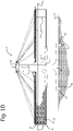
- Figure 1A shows a schematic side view of an exemplary, non-limiting embodiment of a bottom-founded semi-submersible spar-type offshore fish farm 1 according to the invention when being in a so-called tow draft.
- the bottom-founded fish farm 1 can be towed from the yard where the bottom-founded fish farm 1 has been assembled to a desired so-called shallow farming location at sea, i.e. a location where a seabed 27 is located in a range between 25m - 50m below sea level 13.
- the bottom-founded fish farm 1 comprises an elongated center column 2 that has a first end part 3 having a cross-section with a first diameter and a second end part 4 having a cross-section with a second diameter that is larger than the first diameter of the cross-section of the first end part 3.
- the elongated center column 2 in the embodiment shown in figure 1A has a circular cross-section.
- the cross-section of the elongated center column can have any suitable cross-section.
- the second end part 4 is provided with at least one fastening assembly 34 that is configured and arranged to stably associate the second end part 4 of the elongated center column 2 with the seabed 27 at the desired farming location.
- fastening assemblies 34 are shown.
- the fastening assemblies are suction anchors 35.
- the fastening assemblies could comprise pre-piling templates (not shown) that can be associated with pre-drilled piles (not shown) for associating the bottom-founded fish farm 1 to the seabed 27.
- pre-piling templates not shown
- pre-drilled piles not shown
- pre-piling templates may be used.
- the specific embodiment of the fastening assemblies that is required will among others depend on the specific characteristics of the seabed at the desired farming location.
- Figure 1A further shows that the bottom-founded fish farm 1 comprises an elongated buoyancy sleeve 5 that is coaxially arranged around the elongated center column 2.
- the elongated buoyancy sleeve 5 comprises an end portion that is provided with a floater body 6 that extends radially outward with respect to the elongated center column 2.
- the floater body 6 is configured and arranged to stabilize the bottom-founded fish farm 1 when it is in the tow draft and upon movement of the elongated center column 2 and the elongated buoyancy sleeve 5 relative to each other during installation of the fish farm 1 at the farming location.
- the floater body 6 is at sea level 13 and the floater body 6 and the second end part 4 of the elongated center column 2 are in an abutting contact. In this way stable transport of the fish farm is enabled when the fish farm is towed for example from the yard where the fish farm was built to a desired farming location.
- Figure 1A also shows that the bottom-founded semi-submersible spar-type offshore fish farm 1 comprises a semi-submersible netted rigid cage 7 that is coaxially arranged around the elongated buoyancy sleeve 5.
- the semi-submersible netted cage 7 of the bottom-founded fish farm 1 can have a diameter in a range between 80m and 180m.
- the cage 7 comprises a first frame 8 that is coaxially arranged around the elongated buoyancy sleeve 5.
- the first frame 8 is interconnected with the elongated buoyancy sleeve 5 via a first set of elongated connecting elements 9 that are shown in figure 2 .
- the cage 7 also comprises a second frame 11 that is coaxially arranged around the elongated buoyancy sleeve 5 and is arranged below the first frame 8.
- the second frame 11 is interconnected with the floater body 6 of the elongated buoyancy sleeve 5 via a second set of elongated connecting elements 12 that are shown in figure 3 .
- Figure 1A also shows that a third set of elongated connecting elements 14 is provided.
- Each elongated connecting element of the third set of elongated connecting elements 14 is arranged to interconnect the first frame 8 and the second frame 11.
- the elongated connecting elements of the third set of elongated connecting elements 14 can be flexible elements such as chains of metal or any other suitable material such as fiber-enforced resilient material.
- figure 1A shows that an end portion of the elongated buoyancy sleeve 5 is provided with a control facility 21 that in use of the fish farm 1 remains positioned above sea level.
- the control facility 21 comprises an equipment room and a residence room or living quarter for operators of the fish farm 1.
- the person skilled in the art will appreciate that the control facility can comprise any system or equipment that is suitable to be located therein and that is required for the operation of the bottom-founded semi-submersible spar-type fish farm 1. Examples of such systems or equipment, which are not explained in further detail and are not shown in the appended figures, are power systems, generators, e.g.
- FIG. 1A also shows a helicopter landing platform that is provided on the roof of the control facility 21.
- the bottom-founded semi-submersible spar-type offshore fish farm 1 can comprise at least one of a harvesting system, a mooring system, a boat landing system, a docking system, a dead fish removal system and a feeding system.
- the elongated buoyancy sleeve 5 can comprise at least one of ballast/de-ballast pumps, piping systems, ventilation systems, valve systems, level gaging systems and air compressors that in use of the fish farm enable ballasting or de-ballasting operations for allowing the elongated buoyancy sleeve 5 of the fish farm 1 to float upwards or to dive downwards.
- ballast/de-ballast pumps piping systems, ventilation systems, valve systems, level gaging systems and air compressors that in use of the fish farm enable ballasting or de-ballasting operations for allowing the elongated buoyancy sleeve 5 of the fish farm 1 to float upwards or to dive downwards.
- the elongated buoyancy sleeve 5 is naturally buoyant, there is no need for a separate ballasting system in the elongated buoyancy sleeve 5 other than mobile deep well pumps.
- the elongated buoyancy sleeve 5 and the elongated center column 2 are movable with respect to each other in any suitable way, for example in a sliding manner under the influence of a displacement system.
- the displacement system can comprise a winch.
- the person skilled in the art will appreciate that it can be advantageous if at least one of the elongated buoyancy sleeve 5 and the elongated center column 2 is provided with pads comprising a material, e.g. polytetrafluoroethylene (PTFE), that enhances sliding of the elongated buoyancy sleeve 5 along the elongated center column 2.
- PTFE polytetrafluoroethylene
- Figure 1B shows a schematic side view of the exemplary, non-limiting embodiment of the bottom-founded semi-submersible spar-type offshore fish farm 1 shown in figure 1A when being in a so-called installation draft.
- movement of the elongated center column 2 relative to the elongated buoyance sleeve 5 allows lowering of the second end part 4 of the elongated center column 2 towards the seabed 27 in order to subsequently associate the second end part 4 of the elongated center column with the seabed 27 via the suction cans 35.
- the floater body 6 remains at sea level 13 in order to stabilize the fish farm 1.
- FIG 1C shows a schematic side view of the exemplary, non-limiting embodiment of the bottom-founded semi-submersible spar-type offshore fish farm 1 shown in figures 1A and 1B when being in a so-called maintenance draft.
- the floater body 6 of the elongated buoyancy sleeve 5 is positioned at sea level 13 in order to raise the semi-submersible netted rigid cage 7 above sea level. In this way maintenance of the cage can be performed more easily as the maintenance work can be performed at or above sea level.
- the elongated center column 2 that is stably associated with the seabed 27 provides stability to the fish farm 1 when it is in the maintenance draft shown in figure 1C .
- the elongated center column 2 that is stably associated with the seabed 27 provides stability to the fish farm 1 during any movement of the elongated buoyancy sleeve 5 along it.
- FIG 1D shows a schematic side view of the exemplary, non-limiting embodiment of the bottom-founded semi-submersible spar-type offshore fish farm 1 shown in figures 1A-1C when being in a so-called feed draft.
- the floater body 6 of the elongated buoyancy sleeve 5 is positioned between the first end part 3 and the second end part 4 of the elongated center column 2 such that the largest part of the semi-submersible netted rigid cage 7 as seen in an axial direction of the elongated center column 2 is below sea level 13.
- the fish farm 1 is brought into the feed draft to feed the stock that is cultivated in the cage 7.
- the elongated center column 2 provides stability to the bottom-founded fish farm 1.
- FIG 1E shows a schematic side view of the exemplary, non-limiting embodiment of the bottom-founded semi-submersible spar-type offshore fish farm 1 shown in figures 1A-1D when being in a so-called storm draft.
- the person skilled in the art will appreciate that it depends on the actual sea conditions if it is possible to position the semi-submersible netted rigid cage 7 partially above sea level, as is the case in the abovementioned feed draft, or to position it entirely, or almost entirely, above sea level, as is the case in the abovementioned maintenance draft.
- the semi-submersible netted rigid cage 7 is advantageously positioned completely below sea level 13 in order to minimize any negative effects of the sea conditions on the cage 7, the stock, e.g.
- the fish farm 1 can be brought in the storm draft by arranging the floater body 6 of the elongated buoyancy sleeve 5 in an abutting contact with the second end part 4 of the elongated center column 2. As a result, the semi-submersible netted rigid cage 7 is positioned completely below sea level 13.
- FIG. 2 shows a schematic perspective view of an upper part of the bottom-founded semi-submersible spar-type offshore fish farm 1 according to the exemplary, non-limiting embodiment shown in figures 1A-1E .
- each elongated connecting element of the first set of elongated connecting elements 9 is arranged to interconnect the first frame 8 and the elongated buoyancy sleeve 5 via at least one detachable and pivotable coupling assembly 10 that will be explained in further detail in relation to figures 4A and 4B .
- Figure 2 shows that the first frame 8 comprises a first set of frame sections 19 that are connected to each other to form a first closed structure.
- the first frame 8 has buoyant properties and has a circular shape.
- the buoyant properties can be provided in any suitable way, for example by using a tubular lattice structure for the frame sections of the first set of frame sections 19 of the first frame 8. This is explained further in relation to figure 5 .
- the elongated connecting elements are configured to carry at least their own weight and at least part of the weight of at least one of the nets of the semi-submersible netted rigid cage 7 that are connected to them and the respective first frame 8 and the second frame 11 of the semi-submersible netted rigid cage 7.
- Figures 1A-1E and figure 2 also show that for the sake of stability of the semi-submersible netted rigid cage 7, a plurality of guy ropes, e.g. steel wire ropes, is provided that are arranged to interconnect the first frame 8 and the control facility 21.
- Figure 2 shows that the exemplary, non-limiting embodiment of the bottom-founded semi-submersible spar-type offshore fish farm 1 is provided with a first platform 22 that is arranged adjacent to the elongated center column 2 and a second platform 23 that is connected with the first frame 8.
- the first platform 22 and the second platform 23 can be used by operators of the fish farm.
- the first platform 22 and the second platform 23 are interconnected by a walkway that is arranged on an elongated connecting element of the first set of elongated connecting elements 9.
- Figure 2 shows that the first frame 8 is provided with a first net 24 that is used as a top net of the semi-submersible netted rigid cage 7.
- first net 24 is only partially shown, the person skilled in the art will appreciate that in order to be able to position the cage 7 completely below sea level, the first net 24 will have to completely cover any spaces between at least one of the first frame 8, the elongated connecting elements of the first set of elongated connecting elements 9, the first platform 22 and the elongated buoyancy sleeve 5 via which the stock in the cage 7 could escape.
- Figure 2 also shows a part of a second net 25 that as shown in figures 1A-1E is arranged to interconnect the first frame 8 and the second frame 11.
- the second net 25 provides a circumferential side net of the cage 7.
- Figure 3 shows that the second frame 11 is provided with a third net 26 that is used as a bottom net of the cage 7.
- each one of the nets 24, 25, and 26 can comprise one or more parts depending on the specific requirements of the fish farm.
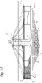
- FIG 3 shows a schematic top view of an exemplary, non-limiting embodiment of the second frame 11, the third net 26 that is used as a bottom net of the semi-submersible rigid cage 7, the floater body 6 and the elongated buoyancy sleeve 5 of the bottom-founded semi-submersible spar-type offshore fish farm 1 according to the exemplary, non-limiting embodiment shown in figures 1A-1E .
- each elongated connecting element of the second set of elongated connecting elements 12 is arranged to interconnect the second frame 11 and the floater body 6 of the elongated buoyancy sleeve 5.
- the third net 26 is only partially shown, the person skilled in the art will appreciate that the third net 26 will have to completely cover any spaces between the second frame 11, the elongated connecting elements of the second set of elongated connecting elements 12 and the floater body 6 via which the stock in the cage 7 could escape.
- Figure 3 also shows that the second frame 11 of the cage 7 comprises a second set of frame sections 20 that are connected to each other to form a second closed structure.
- the second frame 11 has buoyant properties and has a circular shape.
- the buoyant properties can be provided in any suitable way, for example by using a tubular lattice structure for the frame sections of the second set of frame sections 20 of the second frame 11. This is explained further in relation to figure 6 .
- Figure 4A shows a schematic perspective view of an exemplary, non-limiting embodiment of a detachable and pivotable coupling assembly 10.
- Figure 4B shows a schematic side view of the embodiment of the coupling assembly 10 shown in figure 4A .
- the coupling assembly 10 can be used to connect for example an elongated connecting element of the first set of elongated connecting elements 9 with the elongated buoyancy sleeve 5 of the bottom-founded semi-submersible spar-type fish farm 1 according to the invention.
- This is shown in figures 4A and 4B , wherein the first part 15 of the coupling assembly 10 is connected with a surface of the elongated buoyancy sleeve 5 that in use of the fish farm faces away from the elongated center column.
- the second part 16 of the coupling assembly 10 is arranged at an end part of an elongated connecting element of the first set of elongated connecting elements 9.
- an elongated connecting element of the second set of elongated connecting elements 12 can be connected with the floater body of the elongated buoyancy sleeve in the same way using the detachable and pivotable coupling assembly 10.
- Figures 4A and 4B show that the detachable and pivotable coupling assembly 10 comprises a first part 15 and a second part 16 that are detachably connected via a first coupling element 17 that is arranged to provide a first pivot axis around which the first part 15 and the second part 16 are pivotable with respect to each other.
- the detachable and pivotable coupling assembly 10 is used to connect an elongated connecting element of for example the first set of elongated connecting elements 9 with the elongated buoyancy sleeve 5
- the first coupling element 17 allows the first part 15 and the second part 16 to move with respect to each other in radial directions of the elongated center column around which the elongated buoyancy sleeve is arranged.
- a gap D can be seen between the first part 15 of the coupling assembly 10 and the elongated connecting element of the first set of elongated connecting elements 9.
- the gap D enables the aforementioned movements of the first part 15 and the second part 16 with respect to each other.
- an elongated connecting element of the second set of elongated connecting elements can be pivotable with respect to the floater body of the elongated buoyancy sleeve in radial directions of the elongated center column.
- the first coupling element 17 can be any suitable coupling element that can provide the first pivot axis that enables the abovementioned pivoting movements of the first part 15 and the second part 16 of the coupling assembly 10.
- the coupling assembly 10 can comprise more than one first parts and more than one second parts depending on the requirements for the bottom-founded semi-submersible spar-type offshore fish farm, e.g. for the sake of redundancy to improve reliability.
- figures 4A and 4B show an exemplary, non-limiting embodiment of the tubular lattice structure for the elongated connecting elements of the first set of elongated connecting elements 9.
- the person skilled in the art will appreciate that the elongated connecting elements of the second set of elongated connecting elements can have the same tubular lattice structure.
- Figures 4A and 4B also show that the second part 16 of the coupling assembly 10 is provided with a second coupling element 18 that is arranged to provide a second pivot axis that is directed transversely with respect to the first pivot axis.
- a second coupling element 18 that is arranged to provide a second pivot axis that is directed transversely with respect to the first pivot axis.
- an elongated connecting element of for example the first set of elongated connecting elements 9 can also be pivotable with respect to the elongated buoyancy sleeve 5 in circumferential directions of the elongated center column.
- an elongated connecting element of the first set of elongated connecting elements 9 can move with respect to the elongated buoyancy sleeve 5 in orthogonal directions, e.g.
- the movements in radial and circumferential directions of the elongated center column can also be referred to as movements in pitch and yaw. These directions of movement are the most important directions regarding improvement of the life time of the connections between the elongated connecting elements of the first set of elongated connecting elements and at least one of the elongated buoyancy sleeve and the first frame.
- An analogous reasoning holds for the elongated connecting elements of the second set of elongated connecting elements that are pivotable with respect to at least one of the floater body of the elongated buoyancy sleeve and the second frame in both radial and circumferential directions of the elongated center column.
- the second coupling element can be any suitable coupling element that can provide a second pivot axis that is directed transversely with respect to the first pivot axis and that enables the abovementioned movements of the elongated connecting elements of the first set of elongated connecting elements and at least one of the elongated buoyancy sleeve and the first frame, and the elongated connecting elements of the second set of elongated connecting elements and at least one of the floater body of the elongated buoyancy sleeve and the second frame.
- Figures 4A and 4B show that the first part 15 and the second part 16 of the detachable and pivotable coupling assembly 10 are both provided with respective receiving elements, in this particular case holes that are configured and arranged to receive the first coupling element 17. In this way the first part 15 and the second part 16 of the coupling assembly 10 can be connected and detached. In this way maintenance of the bottom-founded fish farm can easily be done at the farming location.
- the coupling assembly 10 also allows easy disassembly of the semi-submersible netted cage.
- the first coupling element 17 is an elongated pin that is configured and arranged to detachably connect the first part 15 and the second part 16 of the coupling assembly 10.
- the second coupling element 18 is a shaft that is configured and arranged to provide the second pivot axis that is directed transversely with respect to the first pivot axis.
- the person skilled in the art will appreciate that the respective first 17 and second 18 coupling elements can be any suitable components that provide the respective first and second pivot axes described above.
- Figure 5 shows a schematic perspective view of an exemplary, non-limiting embodiment of a connection of two frame sections of a first set of frame sections 19 of the first frame of the semi-submersible netted rigid cage of the bottom-founded fish farm according to the invention.
- the two frame sections that have a tubular lattice structure to improve the buoyancy properties of the first frame are connected via a first connecting component 28 that also has a tubular lattice structure.
- the first connecting component 28 can be an integral part of an elongated connecting element of the first set of elongated connecting elements.
- first connecting element 28 can be provided with a first part of the coupling assembly that can be detachably connected with a second part of the coupling assembly that is connected with an end part of the elongated connecting element of the first set of connecting elements.
- the first connecting component 28 comprises a first flange 29 that is provided with a first hole 30 that is configured and arranged to receive an end part of an elongated connecting element of the third set of elongated connecting elements for interconnecting the first frame and the second frame of the semi-submersible netted rigid cage.
- Figure 6 shows a schematic perspective view of an exemplary, non-limiting embodiment of a connection of two frame sections of a second set of frame sections 20 of the second frame of the semi-submersible netted rigid cage of the bottom-founded fish farm according to the invention.
- the two frame sections that have a tubular lattice structure to improve the buoyancy properties of the second frame are connected via a second connecting component 31 that also has a tubular lattice structure.
- the second connecting component 31 can be an integral part of an elongated connecting element of the second set of elongated connecting elements.
- the second connecting element 31 can be provided with a first part of the coupling assembly that can be detachably connected with a second part of the coupling assembly that is connected with an end part of the elongated connecting element of the second set of connecting elements.
- the second connecting component 31 comprises a second flange 32 that is provided with a second hole 33 that is configured and arranged to receive an end part of an elongated connecting element of the third set of elongated connecting elements for interconnecting the first frame and the second frame of the semi-submersible netted rigid cage.
- the present invention can be summarized as relating to a bottom-founded semi-submersible spar-type offshore fish farm 1 for cultivating fish at locations at sea where a seabed is located in a range of 25m - 50m below sea level, comprising an elongated center column 2 comprising a first end part 3 having a cross-section with a first diameter, and a second end part 4 having a cross-section with a second diameter that is larger than the first diameter, the second end part being provided with at least one fastening assembly for stably associating the second end part with the seabed at a farming location.
- Said fish farm also comprises an elongated buoyancy sleeve 5 that is coaxially arranged around the elongated center column and comprises a floater body 6 for stabilizing said fish farm during installation at the farming location.
- the invention also relates to a method of installing said fish farm at a farming location.
Description
- The present invention relates to a bottom-founded semi-submersible spar-type offshore fish farm for cultivating fish at locations at sea where a seabed is located in a range of 25m - 50m below sea level. The invention also relates to a method of installing such a fish farm at a farming location.
- Aquaculture is the farming of aquatic organisms including fish, mollusks, crustaceans and aquatic plants. Farming implies some form of intervention in the rearing process to enhance production, such as regular stocking, feeding, protection from predators. Aquaculture involves cultivating freshwater and saltwater populations under controlled conditions, and can be contrasted with commercial fishing, which is the harvesting of wild fish. Particular kinds of aquaculture include fish farming, shrimp farming, oyster farming, mariculture, algaculture, and the cultivation of ornamental fish. Fish farming using inshore fish farms in freshwater and offshore fish farms in saltwater is well known. An advantage of known semi-submersible spar-type offshore fish farms is that they can be provided with cages that have large harvesting volumes. As a result, a good farming environment can be provided which is the basis for harvesting highquality cultured fish. To limit exposure of the cages and the stock cultivated within them to harsh sea conditions such cages can be submerged during heavy storms or typhoons. In this way, damage to at least one of the cages, the stock cultivated within them and consequently to the semi-submersible spar-type offshore fish farms as a whole can be limited. Documents
US 2012/167829 A1 andUS 3 691 994 A disclose this type of fish farms.Document EP 2 917 097 A1 discloses another type of semi-submersible structure. - A disadvantage of the known semi-submersible spar-type offshore fish farms mentioned above is that their installation at so-called shallow farming locations at sea, i.e. at locations where a seabed is located in a range of 25m - 50m below sea level, is an arduous process that involves cumbersome mooring of the fish farm as it among others requires application of long mooring lines, i.e. mooring lines having a length of at least 1.5 km. As this increases the costs for installing the aforementioned known offshore fish farms at the so-called shallow farming locations at sea, the use of this known type of offshore fish farms at such locations is not preferred. Consequently, there is a need to modify said known semi-submersible spar-type offshore fish farms in order to enable using them at shallow farming locations at sea.
- It is an object of the present invention to provide a bottom-founded semi-submersible spar-type offshore fish farm according to
claim 1 for cultivating fish at so-called shallow farming locations at sea, i.e. at locations where a seabed is located in a range of 25m - 50m below sea level, that pre-empts or at least reduces the abovementioned and/or other disadvantages associated with semi-submersible spar-type offshore fish farms known in the art. - It is also an object of the present invention to provide a method according to
claim 15 of installing such a bottom-founded semi-submersible spar-type offshore fish farm at a shallow farming location at sea. - Aspects of the present invention are set out in the accompanying independent and dependent claims. Features from the dependent claims may be combined with features from the independent claim as appropriate and not merely as explicitly set out in the claims.
- At least one of the abovementioned objects is achieved by a bottom-founded semi-submersible spar-type offshore fish farm for cultivating fish at locations at sea where a seabed is located in a range of 25m - 50m below sea level, comprising an elongated center column comprising a first end part having a cross-section with a first diameter, and a second end part having a cross-section with a second diameter that is larger than the first diameter of the cross-section of the first end part, the second end part being provided with at least one fastening assembly that is configured and arranged to stably associate the second end part of the elongated center column with the seabed at a farming location, an elongated buoyancy sleeve that is coaxially arranged around the elongated center column, the elongated buoyancy sleeve comprising an end portion that is provided with a floater body that is configured and arranged to extend radially outward with respect to the elongated center column and to stabilize said fish farm upon movement of the elongated center column and the elongated buoyancy sleeve relative to each other during installation of said fish farm at the farming location. By providing a bottom-founded semi-submersible spar-type offshore fish farm the use of mooring lines having a length of typically at least 1.5 km can be omitted. This also enables a reduction of the costs for installing this type of offshore fish farms at so-called shallow farming locations at sea, i.e. at locations where a seabed is located in a range of 25m - 50m below sea level. Consequently, the use of semi-submersible spar-type offshore fish farms that are bound to the seabed at shallow farming locations in accordance with the present invention becomes more attractive.
- In an embodiment of the bottom-founded semi-submersible spar-type offshore fish farm according to the invention, at least one of the elongated center column, the elongated buoyancy sleeve and the floater body are configured to allow the floater body to either assume a predetermined position along the elongated center column between the first end part and the second end part thereof or to be in an abutting contact with the second end part of the elongated center column depending on a mode of operation of said fish farm. When the second end part of the elongated center column is stably associated with the seabed, the floater body can be positioned at any desired position along the elongated center column between the first end part and the second end part thereof to bring the fish farm into one of a so-called maintenance draft and a feed draft. In the maintenance draft the floater body will be at a position between the first end part and the second end part of the elongated center column that is at sea level. In the feed draft, the floater body will be at a position between the first end part and the second end part of the elongated center column that is below sea level. By arranging the floater body and the second end part of the elongated center column in an abutting contact the bottom-founded fish farm can be brought into a so-called storm draft in which exposure of the bottom-founded fish farm to harsh sea conditions such as heavy storms or typhoons can be reduced. As a result, damage to the bottom-founded fish farm can be limited.
- An embodiment of the bottom-founded semi-submersible spar-type offshore fish farm according to the invention comprises a semi-submersible netted rigid cage that is coaxially arranged around the elongated buoyancy sleeve, said cage comprising a first frame that is coaxially arranged around the elongated buoyancy sleeve, a first set of elongated connecting elements, wherein each elongated connecting element of the first set of elongated connecting elements is arranged to interconnect the first frame and the elongated buoyancy sleeve via at least one detachable and pivotable coupling assembly, a second frame that is coaxially arranged around the elongated buoyancy sleeve and, in use of said fish farm, is arranged below the first frame, a second set of elongated connecting elements, wherein each elongated connecting element of the second set of elongated connecting elements is arranged to interconnect the second frame and the floater body of the elongated buoyancy sleeve, and a third set of elongated connecting elements, wherein each elongated connecting element of the third set of elongated connecting elements is arranged to interconnect the first frame and the second frame.
- By connecting the elongated connecting elements of the first set of elongated connecting elements with at least one of the elongated buoyancy sleeve and the first frame via detachable and pivotable coupling assemblies, the elongated coupling elements of the first set of elongated connecting elements and at least one of the elongated buoyancy sleeve and the first frame can move relative to each other instead of being fixedly connected. In this way, the connections between the elongated connecting elements of the first set of elongated connecting elements and at least one of the elongated buoyancy sleeve and the first frame have an improved life time due to reduced fatigue because of decreased stress cycles as a result of decreased load variations. The person skilled in the art will appreciate that in another exemplary embodiment of the bottom-founded fish farm the elongated connecting elements of the second set of elongated connecting elements can also be connected with at least one of the second frame and the floater body of the elongated buoyancy sleeve via said detachable and pivotable coupling assemblies. Hence, the abovementioned advantages apply also to the connections between the elongated connecting elements of the second set of elongated connecting elements and at least one of the second frame and the floater body of the elongated buoyancy sleeve.
- Furthermore, because of the fact that the pivotable coupling assembly is detachable, the elongated connecting elements of the respective first and second sets of elongated connecting elements can be assembled and disassembled. In this way maintenance of the bottom-founded fish farm can easily be done at the farming location.
- In an embodiment of the bottom-founded semi-submersible spar-type offshore fish farm according to the invention, the detachable and pivotable coupling assembly comprises a first part and a second part that are detachably connectable via at least a first coupling element that is arranged to provide a first pivot axis around which the first part and the second part are pivotable with respect to each other. In this way an elongated connecting element of the first set of elongated connecting elements, in use of the bottom-founded fish farm, is pivotable with respect to at least one of the elongated buoyancy sleeve and the first frame in radial directions of the elongated center column. Likewise, an elongated connecting element of the second set of elongated connecting elements, in use of the bottom-founded fish farm, is pivotable with respect to at least one of the second frame and the floater body of the elongated buoyancy sleeve in radial directions of the elongated center column. The person skilled in the art will appreciate that the first coupling element can be any suitable coupling element that can provide the first pivot axis that enables the abovementioned pivoting movements of the first part and the second part of the detachable and pivotable coupling assembly. The person skilled in the art will appreciate that the detachable and pivotable coupling assembly can comprise more than one first parts and more than one second parts depending on the requirements for the bottom-founded fish farm, e.g. for the sake of redundancy to improve reliability.
- In an embodiment of the bottom-founded semi-submersible spar-type offshore fish farm according to the invention, at least one of the first part and the second part of the detachable and pivotable coupling assembly is provided with at least a second coupling element that is arranged to provide a second pivot axis that is directed transversely with respect to the first pivot axis. By providing the second coupling element, an elongated connecting element of the first set of elongated connecting elements, in use of the bottom-founded fish farm, is also pivotable with respect to the elongated buoyancy sleeve in circumferential directions of the elongated center column. Hence, an elongated connecting element of the first set of elongated connecting elements can, in use of the bottom-founded fish farm, move with respect to the elongated buoyancy sleeve in orthogonal directions, e.g. in radial directions and in circumferential directions of the elongated center column. The movements in radial and circumferential directions of the elongated center column can also be referred to as movements in pitch and yaw. These directions of movement are the most important directions regarding improvement of the life time of the connections between the elongated connecting elements of the first set of elongated connecting elements and the elongated buoyancy sleeve. An analogous reasoning holds for the elongated connecting elements of the second set of elongated connecting elements that are pivotable with respect to the floater body of the elongated buoyancy sleeve in both radial and circumferential directions of the elongated center column.
- The person skilled in the art will appreciate that the second coupling element can be any suitable coupling element that can provide a second pivot axis that is directed transversely with respect to the first pivot axis and that enables the abovementioned movements of the elongated connecting elements of the first set of elongated connecting elements and the elongated buoyancy sleeve, and the elongated connecting elements of the second set of elongated connecting elements and the floater body of the elongated buoyancy sleeve.
- In an embodiment of the bottom-founded semi-submersible spar-type offshore fish farm according to the invention, at least one of the first frame comprises a first set of frame sections that are connected to each other to form a first closed structure and the second frame comprises a second set of frame sections that are connected to each other to form a second closed structure. In this way at least one of the respective first and second frames can be assembled and disassembled. As a result, maintenance of the bottom-founded fish farm can easily be done at the farming location.
- In an embodiment of the bottom-founded semi-submersible spar-type offshore fish farm according to the invention, at least one of the first frame and the second frame have buoyant properties and have one of a circular and polygonal shape. By providing at least one of the first frame and the second frame with buoyant properties, they can carry at least their own weight. The person skilled in the art will appreciate that the buoyant properties can be provided in any suitable way, e.g. by using a tubular lattice structure for at least one of the first frame and the second frame.
- In an embodiment of the bottom-founded semi-submersible spar-type offshore fish farm according to the invention, the first part of the detachable and pivotable coupling assembly is arranged at least at one of a surface of the elongated buoyancy sleeve that in use of said fish farm faces away from the elongated center column, and a surface of at least one frame section of the first set of frame sections of the first frame. The person skilled in the art will appreciate that the first part of the detachable and pivotable coupling assembly can be arranged at any desired location depending on specific design requirements for the bottom-founded semi-submersible spar-type offshore fish farm.
- In an embodiment of the bottom-founded semi-submersible spar-type offshore fish farm according to the invention, the second part of the detachable and pivotable coupling assembly is arranged at least at one end part of an elongated connecting element of the first set of elongated connecting elements. The person skilled in the art will appreciate that if for example the elongated connecting elements of the first set of elongated connecting elements are provided with second parts of the detachable and pivotable coupling assembly at both of their respective end parts, and the elongated buoyancy sleeve and the frame sections of the first set of frame sections of the first frame are provided with first parts of the detachable and pivotable coupling assembly, upon assembly, the detachable and pivotable coupling assemblies interconnect the elongated connecting elements of the first set of elongated connecting elements with both the elongated buoyancy sleeve and the frame sections of the first set of frame sections of the first frame.
- Analogously, the detachable and pivotable coupling assemblies can be used to interconnect elongated connecting elements of the second set of elongated connecting elements with at least one of the floater body of the elongated buoyancy sleeve and at least one frame section of the second set of frame sections of the second frame. The person skilled in the art will appreciate that many more configurations are conceivable depending on the requirements for the semi-submersible spar-type offshore fish farm.
- In an embodiment of the bottom-founded semi-submersible spar-type offshore fish farm according to the invention, the elongated connecting elements of at least one of the first set of elongated connecting elements and the second set of elongated connecting elements have a tubular lattice structure. In this way, the elongated connecting elements can carry at least their own weight and the weight of the respective first and second frames of the semi-submersible netted rigid cage.
- In an embodiment of the bottom-founded semi-submersible spar-type offshore fish farm according to the invention, said fish farm is provided with at least one of a first platform that, in use of said fish farm, is arranged adjacent to the elongated center column and a second platform that is connected with the first frame. The first platform and the second platform can be used by operators of the bottom-founded fish farm. The first platform and the second platform can be interconnected by at least one walkway that can be arranged on an elongated connecting element of the first set of elongated connecting elements. The person skilled in the art will appreciate that the walkway can be configured and arranged in any suitable way to interconnect the first platform and the second platform.
- In an embodiment of the bottom-founded semi-submersible spar-type offshore fish farm according to the invention, the first frame is provided with a first net that, in use of said fish farm, provides a top net of the semi-submersible netted rigid cage, the first frame and the second frame are further interconnected via a second net that, in use of said fish farm, provides a circumferential side net of said cage, and wherein the second frame is provided with a third net that, in use of said fish farm, provides a bottom net of said cage.
- In an embodiment of the bottom-founded semi-submersible spar-type offshore fish farm according to the invention, the at least one fastening assembly comprises at least one of a suction anchor and a pre-piling template. The person skilled in the art will be familiar with suction anchors and pre-piling templates that can be associated with pre-drilled piles as these techniques are commonly used for associating bottom-founded off-shore structures to the seabed. In an exemplary embodiment of the bottom-founded fish farm only suction cans are used to associate the second end part of the elongated center column with the seabed. In another exemplary embodiment of the bottom-founded fish farm, only pre-piling templates are used to associate the second end part of the elongated center column with the seabed. In yet another exemplary embodiment of the bottom-founded fish farm, a combination of suction cans and pre-piling templates may be used. The specific embodiment required will among others depend on the specific characteristics of the seabed at the desired farming location.
- In an embodiment of the bottom-founded semi-submersible spar-type offshore fish farm according to the invention, the semi-submersible spar-type offshore fish farm comprises at least one of a harvest system, a power system, a mooring system, a boat landing system, a docking system, a dead fish removal system and a feeding system. The person skilled in the art will appreciate that the bottom-founded fish farm according to the invention is a versatile and self-sufficient fish farm.
- According to another aspect the present invention provides a method of installing a bottom-founded semi-submersible spar-type offshore fish farm for cultivating fish at locations where a seabed is located in a range of 25m - 50m below sea level according to the invention, comprising the steps of positioning said fish farm of which the floater body of the elongated buoyancy sleeve and the second end part of the elongated center column are in an abutting contact at a farming location, moving the elongated center column and the elongated buoyancy sleeve relative to each other to bring the second end part of the elongated center column into abutting contact with the seabed at the farming location, associating the second end part of the elongated center column with the seabed at the farming location using at least one fastening assembly, and wherein during the steps of bringing the second end part of the elongated center column into abutting contact with the seabed and associating the second end part with the seabed, the floater body remains located at sea level to stabilize said fish farm. The person skilled in the art will appreciate that the method of installing the bottom-founded fish farm enables a less complicated installation process as the floater body of the elongated buoyancy sleeve stabilizes the bottom-founded fish farm while the second end part of the elongated center column is lowered towards the seabed and while it is attached to the seabed via the at least one fastening assembly that is provided at the second end part of the elongated center column. Furthermore, once the second end part of the elongated center column is attached with the seabed, the elongated center column provides stability to the bottom-founded fish farm upon moving the elongated buoyancy sleeve with respect to the elongated center column in order to bring the fish farm in a farming condition. Based on the foregoing, the person skilled in the art will appreciate that the method of installing the bottom-founded semi-submersible spar-type offshore fish farm according to the invention enables the bottom-founded fish farm to be installed in a self-installing way.
- Further features and advantages of the invention will become apparent from the description of the invention by way of exemplary and non-limiting embodiments of a bottom-founded semi-submersible spar-type offshore fish farm that can be installed using the method according to the present invention.
- The person skilled in the art will appreciate that the described embodiments are exemplary in nature only and not to be construed as limiting the scope of protection in any way. The person skilled in the art will realize that alternatives and equivalent embodiments of the bottom-founded fish farm can be conceived and reduced to practice without departing from the scope of protection of the present invention.
- Reference will be made to the figures on the accompanying drawing sheets. The figures are schematic in nature and therefore not necessarily drawn to scale. Furthermore, equal reference numerals denote equal or similar parts. On the attached drawing sheets,
-
figure 1A shows a schematic side view of an exemplary, non-limiting embodiment of a bottom-founded semi-submersible spar-type offshore fish farm according to the invention when being in a so-called tow draft; -
figure 1B shows a schematic side view of the exemplary, non-limiting embodiment of the bottom-founded semi-submersible spar-type offshore fish farm shown infigure 1A when being in a so-called installation draft; -
figure 1C shows a schematic side view of the exemplary, non-limiting embodiment of the bottom-founded semi-submersible spar-type offshore fish farm shown infigures 1A and1B when being in a so-called maintenance draft; -
figure 1D shows a schematic side view of the exemplary, non-limiting embodiment of the bottom-founded semi-submersible spar-type offshore fish farm shown infigures 1A-1C when being in a so-called feed draft; -
figure 1E shows a schematic side view of the exemplary, non-limiting embodiment of the bottom-founded semi-submersible spar-type offshore fish farm shown infigures 1A-1D when being in a so-called storm draft; -
figure 2 shows a schematic perspective view of an upper part of the bottom-founded semi-submersible spar-type offshore fish farm according to the exemplary, non-limiting embodiment shown infigures 1A-1E ; -
figure 3 shows a schematic top view of an exemplary, non-limiting embodiment of the second frame, a third net that is used as a bottom net of the semi-submersible rigid cage, the floater body and the elongated buoyancy sleeve of the bottom-founded semi-submersible spar-type offshore fish farm according to the exemplary, non-limiting embodiment shown infigures 1A-1E ; -
figure 4A shows a schematic perspective view of an exemplary, non-limiting embodiment of a detachable and pivotable coupling assembly; -
figure 4B shows a schematic side view of the exemplary, non-limiting embodiment of the detachable and pivotable coupling assembly shown infigure 4A ; -
figure 5 shows a schematic perspective view of an exemplary, non-limiting embodiment of a connection of two frame sections of a first set of frame sections of the first frame of the semi-submersible netted rigid cage of the bottom-founded semi-submersible spar-type fish farm according to the invention; and -
figure 6 shows a schematic perspective view of an exemplary, non-limiting embodiment of a connection of two frame sections of a second set of frame sections of the second frame of the semi-submersible netted rigid cage of the bottom-founded semi-submersible spar-type fish farm according to the invention. -
Figure 1A shows a schematic side view of an exemplary, non-limiting embodiment of a bottom-founded semi-submersible spar-typeoffshore fish farm 1 according to the invention when being in a so-called tow draft. In this draft the bottom-foundedfish farm 1 can be towed from the yard where the bottom-foundedfish farm 1 has been assembled to a desired so-called shallow farming location at sea, i.e. a location where aseabed 27 is located in a range between 25m - 50m belowsea level 13. The bottom-foundedfish farm 1 comprises anelongated center column 2 that has afirst end part 3 having a cross-section with a first diameter and asecond end part 4 having a cross-section with a second diameter that is larger than the first diameter of the cross-section of thefirst end part 3. Theelongated center column 2 in the embodiment shown infigure 1A has a circular cross-section. However, the person skilled in the art will appreciate that the cross-section of the elongated center column can have any suitable cross-section. Thesecond end part 4 is provided with at least onefastening assembly 34 that is configured and arranged to stably associate thesecond end part 4 of theelongated center column 2 with theseabed 27 at the desired farming location. - In the exemplary embodiment of the bottom-founded semi-submersible spar-type
offshore fish farm 1 shown infigure 1A , twofastening assemblies 34 are shown. In this case the fastening assemblies are suction anchors 35. In another exemplary embodiment the fastening assemblies could comprise pre-piling templates (not shown) that can be associated with pre-drilled piles (not shown) for associating the bottom-foundedfish farm 1 to theseabed 27. The person skilled in the art will appreciate that in yet another exemplary embodiment of the bottom-foundedfish farm 1, a combination ofsuction cans 35 and pre-piling templates may be used. The specific embodiment of the fastening assemblies that is required will among others depend on the specific characteristics of the seabed at the desired farming location. -
Figure 1A further shows that the bottom-foundedfish farm 1 comprises anelongated buoyancy sleeve 5 that is coaxially arranged around theelongated center column 2. Theelongated buoyancy sleeve 5 comprises an end portion that is provided with afloater body 6 that extends radially outward with respect to theelongated center column 2. Thefloater body 6 is configured and arranged to stabilize the bottom-foundedfish farm 1 when it is in the tow draft and upon movement of theelongated center column 2 and theelongated buoyancy sleeve 5 relative to each other during installation of thefish farm 1 at the farming location. In the tow draft of thefish farm 1 that is shown infigure 1A , thefloater body 6 is atsea level 13 and thefloater body 6 and thesecond end part 4 of theelongated center column 2 are in an abutting contact. In this way stable transport of the fish farm is enabled when the fish farm is towed for example from the yard where the fish farm was built to a desired farming location. -
Figure 1A also shows that the bottom-founded semi-submersible spar-typeoffshore fish farm 1 comprises a semi-submersible netted rigid cage 7 that is coaxially arranged around theelongated buoyancy sleeve 5. The semi-submersible netted cage 7 of the bottom-foundedfish farm 1 can have a diameter in a range between 80m and 180m. The cage 7 comprises afirst frame 8 that is coaxially arranged around theelongated buoyancy sleeve 5. Thefirst frame 8 is interconnected with theelongated buoyancy sleeve 5 via a first set of elongated connectingelements 9 that are shown infigure 2 . The cage 7 also comprises asecond frame 11 that is coaxially arranged around theelongated buoyancy sleeve 5 and is arranged below thefirst frame 8. Thesecond frame 11 is interconnected with thefloater body 6 of theelongated buoyancy sleeve 5 via a second set of elongated connectingelements 12 that are shown infigure 3 .Figure 1A also shows that a third set of elongated connectingelements 14 is provided. Each elongated connecting element of the third set of elongated connectingelements 14 is arranged to interconnect thefirst frame 8 and thesecond frame 11. The elongated connecting elements of the third set of elongated connectingelements 14 can be flexible elements such as chains of metal or any other suitable material such as fiber-enforced resilient material. - Furthermore,
figure 1A shows that an end portion of theelongated buoyancy sleeve 5 is provided with acontrol facility 21 that in use of thefish farm 1 remains positioned above sea level. Thecontrol facility 21 comprises an equipment room and a residence room or living quarter for operators of thefish farm 1. The person skilled in the art will appreciate that the control facility can comprise any system or equipment that is suitable to be located therein and that is required for the operation of the bottom-founded semi-submersible spar-type fish farm 1. Examples of such systems or equipment, which are not explained in further detail and are not shown in the appended figures, are power systems, generators, e.g. solar generators, switch boards, systems related to the fuel tanks and the oil tanks, piping systems, cable systems, and fish farming supporting systems such as CCTV (above and below sea level), communication systems comprising for example radio devices, GPS, a radar system, a telephone system, a broadcasting system and an alarm system.Figure 1A also shows a helicopter landing platform that is provided on the roof of thecontrol facility 21. - Although not explained in further detail nor shown in the appended figures, the person skilled in the art will also appreciate that the bottom-founded semi-submersible spar-type
offshore fish farm 1 can comprise at least one of a harvesting system, a mooring system, a boat landing system, a docking system, a dead fish removal system and a feeding system. - Furthermore, the person skilled in the art will appreciate that although not explicitly described in further detail nor shown in the appended figures, the
elongated buoyancy sleeve 5 can comprise at least one of ballast/de-ballast pumps, piping systems, ventilation systems, valve systems, level gaging systems and air compressors that in use of the fish farm enable ballasting or de-ballasting operations for allowing theelongated buoyancy sleeve 5 of thefish farm 1 to float upwards or to dive downwards. In case theelongated buoyancy sleeve 5 is naturally buoyant, there is no need for a separate ballasting system in theelongated buoyancy sleeve 5 other than mobile deep well pumps. - The person skilled in the art will appreciate that the
elongated buoyancy sleeve 5 and theelongated center column 2 are movable with respect to each other in any suitable way, for example in a sliding manner under the influence of a displacement system. The displacement system can comprise a winch. Furthermore, the person skilled in the art will appreciate that it can be advantageous if at least one of theelongated buoyancy sleeve 5 and theelongated center column 2 is provided with pads comprising a material, e.g. polytetrafluoroethylene (PTFE), that enhances sliding of theelongated buoyancy sleeve 5 along theelongated center column 2. -
Figure 1B shows a schematic side view of the exemplary, non-limiting embodiment of the bottom-founded semi-submersible spar-typeoffshore fish farm 1 shown infigure 1A when being in a so-called installation draft. When thefish farm 1 has reached the desired farming location, movement of theelongated center column 2 relative to theelongated buoyance sleeve 5 allows lowering of thesecond end part 4 of theelongated center column 2 towards theseabed 27 in order to subsequently associate thesecond end part 4 of the elongated center column with theseabed 27 via thesuction cans 35. During the aforementioned steps of the installation process of thefish farm 1, thefloater body 6 remains atsea level 13 in order to stabilize thefish farm 1. -
Figure 1C shows a schematic side view of the exemplary, non-limiting embodiment of the bottom-founded semi-submersible spar-typeoffshore fish farm 1 shown infigures 1A and1B when being in a so-called maintenance draft. In this draft thefloater body 6 of theelongated buoyancy sleeve 5 is positioned atsea level 13 in order to raise the semi-submersible netted rigid cage 7 above sea level. In this way maintenance of the cage can be performed more easily as the maintenance work can be performed at or above sea level. The person skilled in the art will appreciate that theelongated center column 2 that is stably associated with theseabed 27 provides stability to thefish farm 1 when it is in the maintenance draft shown infigure 1C . Moreover, theelongated center column 2 that is stably associated with theseabed 27 provides stability to thefish farm 1 during any movement of theelongated buoyancy sleeve 5 along it. -
Figure 1D shows a schematic side view of the exemplary, non-limiting embodiment of the bottom-founded semi-submersible spar-typeoffshore fish farm 1 shown infigures 1A-1C when being in a so-called feed draft. In this draft thefloater body 6 of theelongated buoyancy sleeve 5 is positioned between thefirst end part 3 and thesecond end part 4 of theelongated center column 2 such that the largest part of the semi-submersible netted rigid cage 7 as seen in an axial direction of theelongated center column 2 is belowsea level 13. Thefish farm 1 is brought into the feed draft to feed the stock that is cultivated in the cage 7. Also in the feed draft, theelongated center column 2 provides stability to the bottom-foundedfish farm 1. -
Figure 1E shows a schematic side view of the exemplary, non-limiting embodiment of the bottom-founded semi-submersible spar-typeoffshore fish farm 1 shown infigures 1A-1D when being in a so-called storm draft. The person skilled in the art will appreciate that it depends on the actual sea conditions if it is possible to position the semi-submersible netted rigid cage 7 partially above sea level, as is the case in the abovementioned feed draft, or to position it entirely, or almost entirely, above sea level, as is the case in the abovementioned maintenance draft. When heavy storms or typhoons are expected the semi-submersible netted rigid cage 7 is advantageously positioned completely belowsea level 13 in order to minimize any negative effects of the sea conditions on the cage 7, the stock, e.g. fish, that is contained within it and the fish farm as a whole. As can be seen fromfigure 1E , thefish farm 1 can be brought in the storm draft by arranging thefloater body 6 of theelongated buoyancy sleeve 5 in an abutting contact with thesecond end part 4 of theelongated center column 2. As a result, the semi-submersible netted rigid cage 7 is positioned completely belowsea level 13. -
Figure 2 shows a schematic perspective view of an upper part of the bottom-founded semi-submersible spar-typeoffshore fish farm 1 according to the exemplary, non-limiting embodiment shown infigures 1A-1E . As is shown infigure 2 , each elongated connecting element of the first set of elongated connectingelements 9 is arranged to interconnect thefirst frame 8 and theelongated buoyancy sleeve 5 via at least one detachable andpivotable coupling assembly 10 that will be explained in further detail in relation tofigures 4A and 4B . -
Figure 2 shows that thefirst frame 8 comprises a first set offrame sections 19 that are connected to each other to form a first closed structure. Thefirst frame 8 has buoyant properties and has a circular shape. The buoyant properties can be provided in any suitable way, for example by using a tubular lattice structure for the frame sections of the first set offrame sections 19 of thefirst frame 8. This is explained further in relation tofigure 5 . To provide the elongated connecting elements of the first set of elongated connectingelements 9 with buoyant properties they have a tubular lattice structure. This is explained further in relation tofigures 4A and 4B . In this way, the elongated connecting elements are configured to carry at least their own weight and at least part of the weight of at least one of the nets of the semi-submersible netted rigid cage 7 that are connected to them and the respectivefirst frame 8 and thesecond frame 11 of the semi-submersible netted rigid cage 7.Figures 1A-1E andfigure 2 also show that for the sake of stability of the semi-submersible netted rigid cage 7, a plurality of guy ropes, e.g. steel wire ropes, is provided that are arranged to interconnect thefirst frame 8 and thecontrol facility 21. -
Figure 2 shows that the exemplary, non-limiting embodiment of the bottom-founded semi-submersible spar-typeoffshore fish farm 1 is provided with afirst platform 22 that is arranged adjacent to theelongated center column 2 and asecond platform 23 that is connected with thefirst frame 8. Thefirst platform 22 and thesecond platform 23 can be used by operators of the fish farm. Thefirst platform 22 and thesecond platform 23 are interconnected by a walkway that is arranged on an elongated connecting element of the first set of elongated connectingelements 9. -
Figure 2 shows that thefirst frame 8 is provided with a first net 24 that is used as a top net of the semi-submersible netted rigid cage 7. Although infigure 2 the first net 24 is only partially shown, the person skilled in the art will appreciate that in order to be able to position the cage 7 completely below sea level, the first net 24 will have to completely cover any spaces between at least one of thefirst frame 8, the elongated connecting elements of the first set of elongated connectingelements 9, thefirst platform 22 and theelongated buoyancy sleeve 5 via which the stock in the cage 7 could escape. -
Figure 2 also shows a part of a second net 25 that as shown infigures 1A-1E is arranged to interconnect thefirst frame 8 and thesecond frame 11. The second net 25 provides a circumferential side net of the cage 7.Figure 3 shows that thesecond frame 11 is provided with a third net 26 that is used as a bottom net of the cage 7. The person skilled in the art will appreciate that each one of thenets -
Figure 3 shows a schematic top view of an exemplary, non-limiting embodiment of thesecond frame 11, the third net 26 that is used as a bottom net of the semi-submersible rigid cage 7, thefloater body 6 and theelongated buoyancy sleeve 5 of the bottom-founded semi-submersible spar-typeoffshore fish farm 1 according to the exemplary, non-limiting embodiment shown infigures 1A-1E . As is shown infigure 3 , each elongated connecting element of the second set of elongated connectingelements 12 is arranged to interconnect thesecond frame 11 and thefloater body 6 of theelongated buoyancy sleeve 5. Although infigure 3 the third net 26 is only partially shown, the person skilled in the art will appreciate that the third net 26 will have to completely cover any spaces between thesecond frame 11, the elongated connecting elements of the second set of elongated connectingelements 12 and thefloater body 6 via which the stock in the cage 7 could escape. -
Figure 3 also shows that thesecond frame 11 of the cage 7 comprises a second set offrame sections 20 that are connected to each other to form a second closed structure. Thesecond frame 11 has buoyant properties and has a circular shape. The buoyant properties can be provided in any suitable way, for example by using a tubular lattice structure for the frame sections of the second set offrame sections 20 of thesecond frame 11. This is explained further in relation tofigure 6 . -
Figure 4A shows a schematic perspective view of an exemplary, non-limiting embodiment of a detachable andpivotable coupling assembly 10.Figure 4B shows a schematic side view of the embodiment of thecoupling assembly 10 shown infigure 4A . Thecoupling assembly 10 can be used to connect for example an elongated connecting element of the first set of elongated connectingelements 9 with theelongated buoyancy sleeve 5 of the bottom-founded semi-submersible spar-type fish farm 1 according to the invention. This is shown infigures 4A and 4B , wherein thefirst part 15 of thecoupling assembly 10 is connected with a surface of theelongated buoyancy sleeve 5 that in use of the fish farm faces away from the elongated center column. Thesecond part 16 of thecoupling assembly 10 is arranged at an end part of an elongated connecting element of the first set of elongated connectingelements 9. The person skilled in the art will appreciate that an elongated connecting element of the second set of elongated connectingelements 12 can be connected with the floater body of the elongated buoyancy sleeve in the same way using the detachable andpivotable coupling assembly 10. -
Figures 4A and 4B show that the detachable andpivotable coupling assembly 10 comprises afirst part 15 and asecond part 16 that are detachably connected via afirst coupling element 17 that is arranged to provide a first pivot axis around which thefirst part 15 and thesecond part 16 are pivotable with respect to each other. When the detachable andpivotable coupling assembly 10 is used to connect an elongated connecting element of for example the first set of elongated connectingelements 9 with theelongated buoyancy sleeve 5, thefirst coupling element 17 allows thefirst part 15 and thesecond part 16 to move with respect to each other in radial directions of the elongated center column around which the elongated buoyancy sleeve is arranged. Infigure 4B a gap D can be seen between thefirst part 15 of thecoupling assembly 10 and the elongated connecting element of the first set of elongated connectingelements 9. The gap D enables the aforementioned movements of thefirst part 15 and thesecond part 16 with respect to each other. Likewise, an elongated connecting element of the second set of elongated connecting elements can be pivotable with respect to the floater body of the elongated buoyancy sleeve in radial directions of the elongated center column. The person skilled in the art will appreciate that thefirst coupling element 17 can be any suitable coupling element that can provide the first pivot axis that enables the abovementioned pivoting movements of thefirst part 15 and thesecond part 16 of thecoupling assembly 10. The person skilled in the art will appreciate that thecoupling assembly 10 can comprise more than one first parts and more than one second parts depending on the requirements for the bottom-founded semi-submersible spar-type offshore fish farm, e.g. for the sake of redundancy to improve reliability. - Moreover,
figures 4A and 4B show an exemplary, non-limiting embodiment of the tubular lattice structure for the elongated connecting elements of the first set of elongated connectingelements 9. The person skilled in the art will appreciate that the elongated connecting elements of the second set of elongated connecting elements can have the same tubular lattice structure. -
Figures 4A and 4B also show that thesecond part 16 of thecoupling assembly 10 is provided with asecond coupling element 18 that is arranged to provide a second pivot axis that is directed transversely with respect to the first pivot axis. The person skilled in the art will appreciate that by providing thesecond coupling element 18, an elongated connecting element of for example the first set of elongated connectingelements 9 can also be pivotable with respect to theelongated buoyancy sleeve 5 in circumferential directions of the elongated center column. Hence, an elongated connecting element of the first set of elongated connectingelements 9 can move with respect to theelongated buoyancy sleeve 5 in orthogonal directions, e.g. in radial directions and in circumferential directions of the elongated center column. The movements in radial and circumferential directions of the elongated center column can also be referred to as movements in pitch and yaw. These directions of movement are the most important directions regarding improvement of the life time of the connections between the elongated connecting elements of the first set of elongated connecting elements and at least one of the elongated buoyancy sleeve and the first frame. An analogous reasoning holds for the elongated connecting elements of the second set of elongated connecting elements that are pivotable with respect to at least one of the floater body of the elongated buoyancy sleeve and the second frame in both radial and circumferential directions of the elongated center column. - The person skilled in the art will appreciate that the second coupling element can be any suitable coupling element that can provide a second pivot axis that is directed transversely with respect to the first pivot axis and that enables the abovementioned movements of the elongated connecting elements of the first set of elongated connecting elements and at least one of the elongated buoyancy sleeve and the first frame, and the elongated connecting elements of the second set of elongated connecting elements and at least one of the floater body of the elongated buoyancy sleeve and the second frame.
-
Figures 4A and 4B show that thefirst part 15 and thesecond part 16 of the detachable andpivotable coupling assembly 10 are both provided with respective receiving elements, in this particular case holes that are configured and arranged to receive thefirst coupling element 17. In this way thefirst part 15 and thesecond part 16 of thecoupling assembly 10 can be connected and detached. In this way maintenance of the bottom-founded fish farm can easily be done at the farming location. The person skilled in the art will appreciate that thecoupling assembly 10 also allows easy disassembly of the semi-submersible netted cage. - In the embodiment of the
coupling assembly 10 shown infigures 4A and 4B , thefirst coupling element 17 is an elongated pin that is configured and arranged to detachably connect thefirst part 15 and thesecond part 16 of thecoupling assembly 10. Thesecond coupling element 18 is a shaft that is configured and arranged to provide the second pivot axis that is directed transversely with respect to the first pivot axis. The person skilled in the art will appreciate that the respective first 17 and second 18 coupling elements can be any suitable components that provide the respective first and second pivot axes described above. -
Figure 5 shows a schematic perspective view of an exemplary, non-limiting embodiment of a connection of two frame sections of a first set offrame sections 19 of the first frame of the semi-submersible netted rigid cage of the bottom-founded fish farm according to the invention. The two frame sections that have a tubular lattice structure to improve the buoyancy properties of the first frame are connected via a first connectingcomponent 28 that also has a tubular lattice structure. Although not shown in the figures, the person skilled in the art will appreciate that the first connectingcomponent 28 can be an integral part of an elongated connecting element of the first set of elongated connecting elements. Furthermore, although not shown in the figures, the person skilled in the art will appreciate that the first connectingelement 28 can be provided with a first part of the coupling assembly that can be detachably connected with a second part of the coupling assembly that is connected with an end part of the elongated connecting element of the first set of connecting elements. The first connectingcomponent 28 comprises afirst flange 29 that is provided with afirst hole 30 that is configured and arranged to receive an end part of an elongated connecting element of the third set of elongated connecting elements for interconnecting the first frame and the second frame of the semi-submersible netted rigid cage. -
Figure 6 shows a schematic perspective view of an exemplary, non-limiting embodiment of a connection of two frame sections of a second set offrame sections 20 of the second frame of the semi-submersible netted rigid cage of the bottom-founded fish farm according to the invention. The two frame sections that have a tubular lattice structure to improve the buoyancy properties of the second frame are connected via a second connectingcomponent 31 that also has a tubular lattice structure. Although not shown in the figures, the person skilled in the art will appreciate that the second connectingcomponent 31 can be an integral part of an elongated connecting element of the second set of elongated connecting elements. Furthermore, although not shown in the figures, the person skilled in the art will appreciate that the second connectingelement 31 can be provided with a first part of the coupling assembly that can be detachably connected with a second part of the coupling assembly that is connected with an end part of the elongated connecting element of the second set of connecting elements. The second connectingcomponent 31 comprises asecond flange 32 that is provided with asecond hole 33 that is configured and arranged to receive an end part of an elongated connecting element of the third set of elongated connecting elements for interconnecting the first frame and the second frame of the semi-submersible netted rigid cage. - The present invention can be summarized as relating to a bottom-founded semi-submersible spar-type
offshore fish farm 1 for cultivating fish at locations at sea where a seabed is located in a range of 25m - 50m below sea level, comprising anelongated center column 2 comprising afirst end part 3 having a cross-section with a first diameter, and asecond end part 4 having a cross-section with a second diameter that is larger than the first diameter, the second end part being provided with at least one fastening assembly for stably associating the second end part with the seabed at a farming location. Said fish farm also comprises anelongated buoyancy sleeve 5 that is coaxially arranged around the elongated center column and comprises afloater body 6 for stabilizing said fish farm during installation at the farming location. The invention also relates to a method of installing said fish farm at a farming location. - It will be clear to a person skilled in the art that the scope of the present invention is not limited to the examples discussed in the foregoing but that several amendments and modifications thereof are possible without deviating from the scope of the present invention as defined by the attached claims. In particular, combinations of specific features of various aspects of the invention may be made. An aspect of the invention may be further advantageously enhanced by adding a feature that was described in relation to another aspect of the invention. While the present invention has been illustrated and described in detail in the figures and the description, such illustration and description are to be considered illustrative or exemplary only, and not restrictive.
- The present invention is not limited to the disclosed embodiments. Variations to the disclosed embodiments can be understood and effected by a person skilled in the art in practicing the claimed invention, from a study of the figures, the description and the attached claims. In the claims, the word "comprising" does not exclude other steps or elements, and the indefinite article "a" or "an" does not exclude a plurality. The mere fact that certain measures are recited in mutually different dependent claims does not indicate that a combination of these measures cannot be used to advantage. Any reference numerals in the claims should not be construed as limiting the scope of the present invention.
-
- 1
- bottom-founded semi-submersible spar-type offshore fish farm
- 2
- elongated center column
- 3
- first end part
- 4
- second end part
- 5
- elongated buoyancy sleeve
- 6
- floater body
- 7
- semi-submersible netted rigid cage
- 8
- first frame
- 9
- first set of elongated connecting elements
- 10
- detachable and pivotable coupling assembly
- 11
- second frame
- 12
- second set of elongated connecting elements
- 13
- sea level
- 14
- third set of elongated connecting elements
- 15
- first part of the detachable and pivotable coupling assembly
- 16
- second part of the detachable and pivotable coupling assembly
- 17
- first coupling element
- 18
- second coupling element
- 19
- first set of frame sections
- 20
- second set of frame sections
- 21
- control facility
- 22
- first platform
- 23
- second platform
- 24
- first net
- 25
- second net
- 26
- third net
- 27
- seabed
- 28
- first connecting component
- 29
- first flange
- 30
- first hole
- 31
- second connecting component
- 32
- second flange
- 33
- second hole
- 34
- fastening assembly
- 35
- suction can
Claims (15)
- A bottom-founded semi-submersible spar-type offshore fish farm (1) for cultivating fish at locations at sea where a seabed is located in a range of 25m - 50m below sea level, comprising:- an elongated center column (2) comprising a first end part (3) having a cross-section with a first diameter, and a second end part (4) having a cross-section with a second diameter that is larger than the first diameter of the cross-section of the first end part, the second end part (4) being provided with at least one fastening assembly (34) that is configured and arranged to bring the second end part (4) of the elongated center column (2) into abutting contact with the seabed at a farming location;- an elongated buoyancy sleeve (5) that is coaxially arranged around the elongated center column (2), the elongated buoyancy sleeve (5) comprising an end portion that is provided with a floater body (6) that is configured and arranged to extend radially outward with respect to the elongated center column (2) and to stabilize said fish farm (1) upon movement of the elongated center column (2) and the elongated buoyancy sleeve (5) relative to each other during installation of said fish farm (1) at the farming location.
- The bottom-founded semi-submersible spar-type offshore fish farm (1) according to claim 1, wherein at least one of the elongated center column (2), the elongated buoyancy sleeve (5) and the floater body (5) are configured to allow the floater body to either assume a predetermined position along the elongated center column (2) between the first end part (3) and the second end part (4) thereof or to be in an abutting contact with the second end part (4) of the elongated center column (2) depending on a mode of operation of said fish farm (1).
- The bottom-founded semi-submersible spar-type offshore fish farm (1) according to claim 1 or 2, comprising a semi-submersible netted rigid cage (7) that is coaxially arranged around the elongated buoyancy sleeve (5), said cage (7) comprising:- a first frame (8) that is coaxially arranged around the elongated buoyancy sleeve (5);- a first set of elongated connecting elements (9), wherein each elongated connecting element of the first set of elongated connecting elements (9) is arranged to interconnect the first frame (8) and the elongated buoyancy sleeve (5) via at least one detachable and pivotable coupling assembly (10);- a second frame (11) that is coaxially arranged around the elongated buoyancy sleeve (5) and, in use of said fish farm (1), is arranged below the first frame (8);- a second set of elongated connecting elements (12), wherein each elongated connecting element of the second set of elongated connecting elements (12) is arranged to interconnect the second frame (11) and the floater body (6) of the elongated buoyancy sleeve (5); and- a third set of elongated connecting elements (14), wherein each elongated connecting element of the third set of elongated connecting elements (14) is arranged to interconnect the first frame (8) and the second frame (11).
- The bottom-founded semi-submersible spar-type offshore fish farm (1) according to claim 3, wherein the detachable and pivotable coupling assembly (10) comprises a first part (15) and a second part (16) that are detachably connectable via at least a first coupling element (17) that is arranged to provide a first pivot axis around which the first part (15) and the second part (16) are pivotable with respect to each other.
- The bottom-founded semi-submersible spar-type offshore fish farm (1) according to claim 4, wherein at least one of the first part (15) and the second part (16) of the detachable and pivotable coupling assembly (10) is provided with at least a second coupling element (18) that is arranged to provide a second pivot axis that is directed transversely with respect to the first pivot axis.
- The bottom-founded semi-submersible spar-type offshore fish farm (1) according to any one of the claims 3 to 5, wherein at least one of the first frame (8) comprises a first set of frame sections (19) that are connected to each other to form a first closed structure and the second frame (11) comprises a second set of frame sections (20) that are connected to each other to form a second closed structure.
- The bottom-founded semi-submersible spar-type offshore fish farm (1) according to any one of the claims 3 to 6, wherein at least one of the first frame (8) and the second frame (11) have buoyant properties and have one of a circular and polygonal shape.
- The bottom-founded semi-submersible spar-type offshore fish farm (1) according to any one of the claims 4 to 7, wherein the first part (15) of the detachable and pivotable coupling assembly (10) is arranged at least at one of a surface of the elongated buoyancy sleeve (5) that in use of said fish farm faces away from the elongated center column (2), and a surface of at least one frame section of the first set of frame sections (19) of the first frame (8).
- The bottom-founded semi-submersible spar-type offshore fish farm (1) according to any one of the claims 4 to 8, wherein the second part (16) of the detachable and pivotable coupling assembly (10) is arranged at least at one end part of an elongated connecting element of the first set of elongated connecting elements (9).
- The bottom-founded semi-submersible spar-type offshore fish farm (1) according to any one of the claims 3 to 9, wherein the elongated connecting elements of at least one of the first set of elongated connecting elements (9) and the second set of elongated connecting elements (12) have a tubular lattice structure.
- The bottom-founded semi-submersible spar-type offshore fish farm (1) according to any one of the preceding claims 3 to 10, wherein said fish farm (1) is provided with at least one of a first platform (22) that, in use of said fish farm (1), is arranged adjacent to the elongated center column (2) and a second platform (23) that is connected with the first frame (8).
- The bottom-founded semi-submersible spar-type offshore fish farm (1) according to any one of the preceding claims 3 to 11, wherein the first frame (8) is provided with a first net (24) that, in use of said fish farm (1), provides a top net of the semi-submersible netted rigid cage (7), the first frame (8) and the second frame (11) are further interconnected via a second net (25) that, in use of said fish farm (1), provides a circumferential side net of said cage (7), and wherein the second frame (11) is provided with a third net (26) that, in use of said fish farm (1), provides a bottom net of said cage (7).
- The bottom-founded semi-submersible spar-type offshore fish farm (1) according to any one of the preceding claims, wherein the at least one fastening assembly (34) comprises at least one of a suction anchor (35) and a pre-piling template.
- The bottom-founded semi-submersible spar-type offshore fish farm (1) according to any one of the preceding claims, wherein the semi-submersible spar-type offshore fish farm (1) comprises at least one of a harvest system, a power system, a mooring system, a boat landing system, a docking system, a dead fish removal system and a feeding system.
- A method of installing a bottom-founded semi-submersible spar-type offshore fish farm (1) for cultivating fish at locations where a seabed is located in a range of 25m - 50m below sea level according to any one of the preceding claims, comprising the steps of:- positioning said fish farm (1) of which the floater body (6) of the elongated buoyancy sleeve (5) and the second end part (4) of the elongated center column (2) are in an abutting contact at a farming location;- moving the elongated center column (2) and the elongated buoyancy sleeve (5) relative to each other to bring the second end part (4) of the elongated center column (2) into abutting contact with the seabed at the farming location;- associating the second end part (4) of the elongated center column (2) with the seabed at the farming location using at least one fastening assembly (34); andwherein during the steps of bringing the second end part (4) of the elongated center column (2) into abutting contact with the seabed and associating the second end part (4) with the seabed, the floater body (6) remains located at sea level to stabilize said fish farm (1).
Applications Claiming Priority (2)
| Application Number | Priority Date | Filing Date | Title |
|---|---|---|---|
| EP18194441 | 2018-09-14 | ||
| PCT/EP2019/074344 WO2020053331A1 (en) | 2018-09-14 | 2019-09-12 | Bottom-founded semi-submersible spar-type offshore fish farm and method of installing the same |
Publications (2)
| Publication Number | Publication Date |
|---|---|
| EP3849302A1 EP3849302A1 (en) | 2021-07-21 |
| EP3849302B1 true EP3849302B1 (en) | 2022-06-22 |
Family
ID=63592558
Family Applications (1)
| Application Number | Title | Priority Date | Filing Date |
|---|---|---|---|
| EP19765504.6A Active EP3849302B1 (en) | 2018-09-14 | 2019-09-12 | Bottom-founded semi-submersible spar-type offshore fish farm and method of installing the same |
Country Status (3)
| Country | Link |
|---|---|
| EP (1) | EP3849302B1 (en) |
| DK (1) | DK3849302T3 (en) |
| WO (1) | WO2020053331A1 (en) |
Families Citing this family (2)
| Publication number | Priority date | Publication date | Assignee | Title |
|---|---|---|---|---|
| CN113068645B (en) * | 2021-04-15 | 2022-04-08 | 广东海洋大学 | Shallow water steel pipe sinking net cage structure |
| NO347443B1 (en) * | 2022-02-04 | 2023-11-06 | Subsea Harvest As | Submerged enclosures for fish |
Citations (1)
| Publication number | Priority date | Publication date | Assignee | Title |
|---|---|---|---|---|
| EP2917097B1 (en) * | 2012-11-06 | 2017-02-15 | Mecal Wind Turbine Design B.V. | Floatable transportation and installation structure for transportation and installation of a floating wind turbine, a floating wind turbine and method for transportation and installation of the same |
Family Cites Families (4)
| Publication number | Priority date | Publication date | Assignee | Title |
|---|---|---|---|---|
| US3691994A (en) * | 1971-05-06 | 1972-09-19 | Aqua Genetics Inc | Floating fish enclosure |
| AUPP178398A0 (en) * | 1998-02-11 | 1998-03-05 | Mcrobert, Ian | Apparatus and method for lifting a net of an aquaculture pen and an aquaculture pen incorporating same |
| KR101948670B1 (en) * | 2010-12-29 | 2019-02-15 | 오션스파 인코퍼레이티드 | Center spar fish pen |
| CN205196711U (en) * | 2015-12-03 | 2016-05-04 | 山东大学 | Formula deep water controllable over -and -under type ocean cage -culture device entirely dives |
-
2019
- 2019-09-12 EP EP19765504.6A patent/EP3849302B1/en active Active
- 2019-09-12 DK DK19765504.6T patent/DK3849302T3/en active
- 2019-09-12 WO PCT/EP2019/074344 patent/WO2020053331A1/en unknown
Patent Citations (1)
| Publication number | Priority date | Publication date | Assignee | Title |
|---|---|---|---|---|
| EP2917097B1 (en) * | 2012-11-06 | 2017-02-15 | Mecal Wind Turbine Design B.V. | Floatable transportation and installation structure for transportation and installation of a floating wind turbine, a floating wind turbine and method for transportation and installation of the same |
Also Published As
| Publication number | Publication date |
|---|---|
| WO2020053331A1 (en) | 2020-03-19 |
| DK3849302T3 (en) | 2022-07-25 |
| EP3849302A1 (en) | 2021-07-21 |
Similar Documents
| Publication | Publication Date | Title |
|---|---|---|
| EP3687286B1 (en) | Semi-submersible spar-type offshore fish farm with detachable and pivotable coupling assembly | |
| EP3426024B1 (en) | Semi-submersible fish farming system | |
| EP3209124B1 (en) | Submersible cage for aquaculture and method of adjusting the depth of said cage | |
| EP3849302B1 (en) | Bottom-founded semi-submersible spar-type offshore fish farm and method of installing the same | |
| KR102146159B1 (en) | Submergible fish cage having double buoys and net made of multiple materials | |
| AU2019210923B2 (en) | Semi-submersible spar-type offshore fish farm with an adjustable ballast system | |
| CN104351103A (en) | Large-scale shallow sea purse net culture device | |
| CN111528153A (en) | Offshore fishery net cage culture structure based on offshore wind power jacket | |
| KR20170012193A (en) | Automatic surfacing apparatus for purple laver cultivation, cultivation apparatus, and automatic surfacing method using tidal ranges | |
| CN114793976A (en) | Lifting system for aquaculture net cage | |
| US20210029974A1 (en) | Fish pen for open sea aquaculture | |
| KR20210025008A (en) | An open sea farm | |
| WO2004016079A1 (en) | Fish enclosure | |
| WO2007125363A1 (en) | Fish enclosure | |
| JP2004305042A (en) | Method for cultivating bottom layer fishes such as flounder or turbot on sea bottom and method for feeding the fishes | |
| CN106719214A (en) | A kind of installation and application of submarine formula wind wave-resisting net casing | |
| DK179794B1 (en) | Offshore fish farm | |
| RU2669304C1 (en) | Construction for growing marine hydrobionts on the shelf and the continental margin | |
| NO346190B1 (en) | Load-bearing connecting element | |
| NO342970B1 (en) | Artificial seabed, cultivation rig comprising said artificial seabed, and methods of moving the same. | |
| KR101353203B1 (en) | Rise-prevening upholder for seaweed and fish cage culture area | |
| CN116868932A (en) | Offshore wind power pile foundation anchoring culture platform and arrangement method | |
| NO346662B1 (en) | Submersible fish cage for sea-based farming |
Legal Events
| Date | Code | Title | Description |
|---|---|---|---|
| STAA | Information on the status of an ep patent application or granted ep patent |
Free format text: STATUS: UNKNOWN |
|
| STAA | Information on the status of an ep patent application or granted ep patent |
Free format text: STATUS: THE INTERNATIONAL PUBLICATION HAS BEEN MADE |
|
| PUAI | Public reference made under article 153(3) epc to a published international application that has entered the european phase |
Free format text: ORIGINAL CODE: 0009012 |
|
| STAA | Information on the status of an ep patent application or granted ep patent |
Free format text: STATUS: REQUEST FOR EXAMINATION WAS MADE |
|
| 17P | Request for examination filed |
Effective date: 20210408 |
|
| AK | Designated contracting states |
Kind code of ref document: A1 Designated state(s): AL AT BE BG CH CY CZ DE DK EE ES FI FR GB GR HR HU IE IS IT LI LT LU LV MC MK MT NL NO PL PT RO RS SE SI SK SM TR |
|
| DAV | Request for validation of the european patent (deleted) | ||
| DAX | Request for extension of the european patent (deleted) | ||
| GRAP | Despatch of communication of intention to grant a patent |
Free format text: ORIGINAL CODE: EPIDOSNIGR1 |
|
| RIC1 | Information provided on ipc code assigned before grant |
Ipc: A01K 61/65 20170101ALI20220222BHEP Ipc: A01K 61/60 20170101AFI20220222BHEP |
|
| STAA | Information on the status of an ep patent application or granted ep patent |
Free format text: STATUS: GRANT OF PATENT IS INTENDED |
|
| INTG | Intention to grant announced |
Effective date: 20220331 |
|
| GRAS | Grant fee paid |
Free format text: ORIGINAL CODE: EPIDOSNIGR3 |
|
| GRAA | (expected) grant |
Free format text: ORIGINAL CODE: 0009210 |
|
| STAA | Information on the status of an ep patent application or granted ep patent |
Free format text: STATUS: THE PATENT HAS BEEN GRANTED |
|
| AK | Designated contracting states |
Kind code of ref document: B1 Designated state(s): AL AT BE BG CH CY CZ DE DK EE ES FI FR GB GR HR HU IE IS IT LI LT LU LV MC MK MT NL NO PL PT RO RS SE SI SK SM TR |
|
| REG | Reference to a national code |
Ref country code: GB Ref legal event code: FG4D |
|
| REG | Reference to a national code |
Ref country code: CH Ref legal event code: EP |
|
| REG | Reference to a national code |
Ref country code: DE Ref legal event code: R096 Ref document number: 602019016237 Country of ref document: DE |
|
| REG | Reference to a national code |
Ref country code: AT Ref legal event code: REF Ref document number: 1499198 Country of ref document: AT Kind code of ref document: T Effective date: 20220715 |
|
| REG | Reference to a national code |
Ref country code: IE Ref legal event code: FG4D |
|
| REG | Reference to a national code |
Ref country code: DK Ref legal event code: T3 Effective date: 20220719 |
|
| REG | Reference to a national code |
Ref country code: NL Ref legal event code: FP |
|
| REG | Reference to a national code |
Ref country code: LT Ref legal event code: MG9D |
|
| PG25 | Lapsed in a contracting state [announced via postgrant information from national office to epo] |
Ref country code: SE Free format text: LAPSE BECAUSE OF FAILURE TO SUBMIT A TRANSLATION OF THE DESCRIPTION OR TO PAY THE FEE WITHIN THE PRESCRIBED TIME-LIMIT Effective date: 20220622 Ref country code: NO Free format text: LAPSE BECAUSE OF FAILURE TO SUBMIT A TRANSLATION OF THE DESCRIPTION OR TO PAY THE FEE WITHIN THE PRESCRIBED TIME-LIMIT Effective date: 20220922 Ref country code: LT Free format text: LAPSE BECAUSE OF FAILURE TO SUBMIT A TRANSLATION OF THE DESCRIPTION OR TO PAY THE FEE WITHIN THE PRESCRIBED TIME-LIMIT Effective date: 20220622 Ref country code: HR Free format text: LAPSE BECAUSE OF FAILURE TO SUBMIT A TRANSLATION OF THE DESCRIPTION OR TO PAY THE FEE WITHIN THE PRESCRIBED TIME-LIMIT Effective date: 20220622 Ref country code: GR Free format text: LAPSE BECAUSE OF FAILURE TO SUBMIT A TRANSLATION OF THE DESCRIPTION OR TO PAY THE FEE WITHIN THE PRESCRIBED TIME-LIMIT Effective date: 20220923 Ref country code: FI Free format text: LAPSE BECAUSE OF FAILURE TO SUBMIT A TRANSLATION OF THE DESCRIPTION OR TO PAY THE FEE WITHIN THE PRESCRIBED TIME-LIMIT Effective date: 20220622 Ref country code: BG Free format text: LAPSE BECAUSE OF FAILURE TO SUBMIT A TRANSLATION OF THE DESCRIPTION OR TO PAY THE FEE WITHIN THE PRESCRIBED TIME-LIMIT Effective date: 20220922 |
|
| REG | Reference to a national code |
Ref country code: AT Ref legal event code: MK05 Ref document number: 1499198 Country of ref document: AT Kind code of ref document: T Effective date: 20220622 |
|
| PG25 | Lapsed in a contracting state [announced via postgrant information from national office to epo] |
Ref country code: RS Free format text: LAPSE BECAUSE OF FAILURE TO SUBMIT A TRANSLATION OF THE DESCRIPTION OR TO PAY THE FEE WITHIN THE PRESCRIBED TIME-LIMIT Effective date: 20220622 Ref country code: LV Free format text: LAPSE BECAUSE OF FAILURE TO SUBMIT A TRANSLATION OF THE DESCRIPTION OR TO PAY THE FEE WITHIN THE PRESCRIBED TIME-LIMIT Effective date: 20220622 |
|
| PG25 | Lapsed in a contracting state [announced via postgrant information from national office to epo] |
Ref country code: SM Free format text: LAPSE BECAUSE OF FAILURE TO SUBMIT A TRANSLATION OF THE DESCRIPTION OR TO PAY THE FEE WITHIN THE PRESCRIBED TIME-LIMIT Effective date: 20220622 Ref country code: SK Free format text: LAPSE BECAUSE OF FAILURE TO SUBMIT A TRANSLATION OF THE DESCRIPTION OR TO PAY THE FEE WITHIN THE PRESCRIBED TIME-LIMIT Effective date: 20220622 Ref country code: RO Free format text: LAPSE BECAUSE OF FAILURE TO SUBMIT A TRANSLATION OF THE DESCRIPTION OR TO PAY THE FEE WITHIN THE PRESCRIBED TIME-LIMIT Effective date: 20220622 Ref country code: PT Free format text: LAPSE BECAUSE OF FAILURE TO SUBMIT A TRANSLATION OF THE DESCRIPTION OR TO PAY THE FEE WITHIN THE PRESCRIBED TIME-LIMIT Effective date: 20221024 Ref country code: ES Free format text: LAPSE BECAUSE OF FAILURE TO SUBMIT A TRANSLATION OF THE DESCRIPTION OR TO PAY THE FEE WITHIN THE PRESCRIBED TIME-LIMIT Effective date: 20220622 Ref country code: EE Free format text: LAPSE BECAUSE OF FAILURE TO SUBMIT A TRANSLATION OF THE DESCRIPTION OR TO PAY THE FEE WITHIN THE PRESCRIBED TIME-LIMIT Effective date: 20220622 Ref country code: CZ Free format text: LAPSE BECAUSE OF FAILURE TO SUBMIT A TRANSLATION OF THE DESCRIPTION OR TO PAY THE FEE WITHIN THE PRESCRIBED TIME-LIMIT Effective date: 20220622 Ref country code: AT Free format text: LAPSE BECAUSE OF FAILURE TO SUBMIT A TRANSLATION OF THE DESCRIPTION OR TO PAY THE FEE WITHIN THE PRESCRIBED TIME-LIMIT Effective date: 20220622 |
|
| PG25 | Lapsed in a contracting state [announced via postgrant information from national office to epo] |
Ref country code: PL Free format text: LAPSE BECAUSE OF FAILURE TO SUBMIT A TRANSLATION OF THE DESCRIPTION OR TO PAY THE FEE WITHIN THE PRESCRIBED TIME-LIMIT Effective date: 20220622 Ref country code: IS Free format text: LAPSE BECAUSE OF FAILURE TO SUBMIT A TRANSLATION OF THE DESCRIPTION OR TO PAY THE FEE WITHIN THE PRESCRIBED TIME-LIMIT Effective date: 20221022 |
|
| REG | Reference to a national code |
Ref country code: DE Ref legal event code: R097 Ref document number: 602019016237 Country of ref document: DE |
|
| PG25 | Lapsed in a contracting state [announced via postgrant information from national office to epo] |
Ref country code: AL Free format text: LAPSE BECAUSE OF FAILURE TO SUBMIT A TRANSLATION OF THE DESCRIPTION OR TO PAY THE FEE WITHIN THE PRESCRIBED TIME-LIMIT Effective date: 20220622 |
|
| PG25 | Lapsed in a contracting state [announced via postgrant information from national office to epo] |
Ref country code: MC Free format text: LAPSE BECAUSE OF FAILURE TO SUBMIT A TRANSLATION OF THE DESCRIPTION OR TO PAY THE FEE WITHIN THE PRESCRIBED TIME-LIMIT Effective date: 20220622 |
|
| PLBE | No opposition filed within time limit |
Free format text: ORIGINAL CODE: 0009261 |
|
| REG | Reference to a national code |
Ref country code: CH Ref legal event code: PL |
|
| STAA | Information on the status of an ep patent application or granted ep patent |
Free format text: STATUS: NO OPPOSITION FILED WITHIN TIME LIMIT |
|
| REG | Reference to a national code |
Ref country code: BE Ref legal event code: MM Effective date: 20220930 |
|
| 26N | No opposition filed |
Effective date: 20230323 |
|
| PG25 | Lapsed in a contracting state [announced via postgrant information from national office to epo] |
Ref country code: LU Free format text: LAPSE BECAUSE OF NON-PAYMENT OF DUE FEES Effective date: 20220912 |
|
| PG25 | Lapsed in a contracting state [announced via postgrant information from national office to epo] |
Ref country code: LI Free format text: LAPSE BECAUSE OF NON-PAYMENT OF DUE FEES Effective date: 20220930 Ref country code: FR Free format text: LAPSE BECAUSE OF NON-PAYMENT OF DUE FEES Effective date: 20220930 Ref country code: CH Free format text: LAPSE BECAUSE OF NON-PAYMENT OF DUE FEES Effective date: 20220930 |
|
| PG25 | Lapsed in a contracting state [announced via postgrant information from national office to epo] |
Ref country code: SI Free format text: LAPSE BECAUSE OF FAILURE TO SUBMIT A TRANSLATION OF THE DESCRIPTION OR TO PAY THE FEE WITHIN THE PRESCRIBED TIME-LIMIT Effective date: 20220622 |
|
| PG25 | Lapsed in a contracting state [announced via postgrant information from national office to epo] |
Ref country code: BE Free format text: LAPSE BECAUSE OF NON-PAYMENT OF DUE FEES Effective date: 20220930 |
|
| PGFP | Annual fee paid to national office [announced via postgrant information from national office to epo] |
Ref country code: NL Payment date: 20230816 Year of fee payment: 5 |
|
| PGFP | Annual fee paid to national office [announced via postgrant information from national office to epo] |
Ref country code: IE Payment date: 20230809 Year of fee payment: 5 Ref country code: GB Payment date: 20230803 Year of fee payment: 5 |
|
| PGFP | Annual fee paid to national office [announced via postgrant information from national office to epo] |
Ref country code: DK Payment date: 20230914 Year of fee payment: 5 Ref country code: DE Payment date: 20230802 Year of fee payment: 5 |
|
| PG25 | Lapsed in a contracting state [announced via postgrant information from national office to epo] |
Ref country code: IT Free format text: LAPSE BECAUSE OF FAILURE TO SUBMIT A TRANSLATION OF THE DESCRIPTION OR TO PAY THE FEE WITHIN THE PRESCRIBED TIME-LIMIT Effective date: 20220622 |