EP3849237B1 - Procédé et appareil permettant de demander des ressources de transmission de liaison latérale dans un système de communication sans fil - Google Patents
Procédé et appareil permettant de demander des ressources de transmission de liaison latérale dans un système de communication sans fil Download PDFInfo
- Publication number
- EP3849237B1 EP3849237B1 EP20213312.0A EP20213312A EP3849237B1 EP 3849237 B1 EP3849237 B1 EP 3849237B1 EP 20213312 A EP20213312 A EP 20213312A EP 3849237 B1 EP3849237 B1 EP 3849237B1
- Authority
- EP
- European Patent Office
- Prior art keywords
- sidelink
- qos
- slrb
- message
- configuration
- Prior art date
- Legal status (The legal status is an assumption and is not a legal conclusion. Google has not performed a legal analysis and makes no representation as to the accuracy of the status listed.)
- Active
Links
- 230000005540 biological transmission Effects 0.000 title claims description 83
- 238000000034 method Methods 0.000 title claims description 64
- 238000004891 communication Methods 0.000 title description 140
- 208000016344 lissencephaly with cerebellar hypoplasia Diseases 0.000 description 40
- 230000000977 initiatory effect Effects 0.000 description 23
- 230000011664 signaling Effects 0.000 description 20
- CQMJEZQEVXQEJB-UHFFFAOYSA-N 1-hydroxy-1,3-dioxobenziodoxole Chemical compound C1=CC=C2I(O)(=O)OC(=O)C2=C1 CQMJEZQEVXQEJB-UHFFFAOYSA-N 0.000 description 14
- 238000013507 mapping Methods 0.000 description 12
- JCKGSPAAPQRPBW-OAQYLSRUSA-N 8-fluoro-n-[(2r)-1-oxo-1-pyrrolidin-1-yl-3-[3-(trifluoromethyl)phenyl]propan-2-yl]-1,2,3,4-tetrahydroisoquinoline-6-sulfonamide Chemical compound C([C@@H](NS(=O)(=O)C=1C=C(C=2CNCCC=2C=1)F)C(=O)N1CCCC1)C1=CC=CC(C(F)(F)F)=C1 JCKGSPAAPQRPBW-OAQYLSRUSA-N 0.000 description 10
- 230000008859 change Effects 0.000 description 8
- 238000005259 measurement Methods 0.000 description 8
- 230000008569 process Effects 0.000 description 8
- 238000010586 diagram Methods 0.000 description 7
- 230000007246 mechanism Effects 0.000 description 7
- 230000004044 response Effects 0.000 description 6
- 238000012986 modification Methods 0.000 description 5
- 230000004048 modification Effects 0.000 description 5
- 230000001960 triggered effect Effects 0.000 description 5
- 101150014328 RAN2 gene Proteins 0.000 description 4
- 238000007726 management method Methods 0.000 description 4
- XHSQDZXAVJRBMX-UHFFFAOYSA-N 2-(5,6-dichlorobenzimidazol-1-yl)-5-(hydroxymethyl)oxolane-3,4-diol Chemical compound OC1C(O)C(CO)OC1N1C2=CC(Cl)=C(Cl)C=C2N=C1 XHSQDZXAVJRBMX-UHFFFAOYSA-N 0.000 description 3
- 102100022734 Acyl carrier protein, mitochondrial Human genes 0.000 description 3
- 101000678845 Homo sapiens Acyl carrier protein, mitochondrial Proteins 0.000 description 3
- 230000001143 conditioned effect Effects 0.000 description 3
- 238000013461 design Methods 0.000 description 3
- 238000001514 detection method Methods 0.000 description 3
- 239000011159 matrix material Substances 0.000 description 3
- 238000012545 processing Methods 0.000 description 3
- 238000013468 resource allocation Methods 0.000 description 3
- 108091005487 SCARB1 Proteins 0.000 description 2
- 102100037118 Scavenger receptor class B member 1 Human genes 0.000 description 2
- 230000006835 compression Effects 0.000 description 2
- 238000007906 compression Methods 0.000 description 2
- 238000004590 computer program Methods 0.000 description 2
- 238000005516 engineering process Methods 0.000 description 2
- 230000006870 function Effects 0.000 description 2
- 230000007774 longterm Effects 0.000 description 2
- 238000010295 mobile communication Methods 0.000 description 2
- 230000003287 optical effect Effects 0.000 description 2
- 239000002245 particle Substances 0.000 description 2
- 238000012546 transfer Methods 0.000 description 2
- TXZPMHLMPKIUGK-UHFFFAOYSA-N 2-methoxy-N-(3-methyl-2-oxo-1,4-dihydroquinazolin-6-yl)benzenesulfonamide Chemical compound COC1=CC=CC=C1S(=O)(=O)NC1=CC=C(NC(=O)N(C)C2)C2=C1 TXZPMHLMPKIUGK-UHFFFAOYSA-N 0.000 description 1
- 101100150275 Caenorhabditis elegans srb-3 gene Proteins 0.000 description 1
- 101000741965 Homo sapiens Inactive tyrosine-protein kinase PRAG1 Proteins 0.000 description 1
- 102100038659 Inactive tyrosine-protein kinase PRAG1 Human genes 0.000 description 1
- 238000013459 approach Methods 0.000 description 1
- 238000013475 authorization Methods 0.000 description 1
- 230000009286 beneficial effect Effects 0.000 description 1
- 230000000295 complement effect Effects 0.000 description 1
- 238000012790 confirmation Methods 0.000 description 1
- 230000001419 dependent effect Effects 0.000 description 1
- QCIJLRJBZDBVDB-UHFFFAOYSA-N n-(1,3-dimethyl-2-oxo-6-pyrrolidin-1-ylbenzimidazol-5-yl)-2-methoxybenzamide Chemical compound COC1=CC=CC=C1C(=O)NC(C(=C1)N2CCCC2)=CC2=C1N(C)C(=O)N2C QCIJLRJBZDBVDB-UHFFFAOYSA-N 0.000 description 1
- 230000008520 organization Effects 0.000 description 1
- 239000005022 packaging material Substances 0.000 description 1
- 230000001360 synchronised effect Effects 0.000 description 1
- 238000012384 transportation and delivery Methods 0.000 description 1
Images


Classifications
-
- H—ELECTRICITY
- H04—ELECTRIC COMMUNICATION TECHNIQUE
- H04W—WIRELESS COMMUNICATION NETWORKS
- H04W28/00—Network traffic management; Network resource management
- H04W28/02—Traffic management, e.g. flow control or congestion control
- H04W28/0268—Traffic management, e.g. flow control or congestion control using specific QoS parameters for wireless networks, e.g. QoS class identifier [QCI] or guaranteed bit rate [GBR]
-
- H—ELECTRICITY
- H04—ELECTRIC COMMUNICATION TECHNIQUE
- H04W—WIRELESS COMMUNICATION NETWORKS
- H04W28/00—Network traffic management; Network resource management
- H04W28/16—Central resource management; Negotiation of resources or communication parameters, e.g. negotiating bandwidth or QoS [Quality of Service]
- H04W28/24—Negotiating SLA [Service Level Agreement]; Negotiating QoS [Quality of Service]
-
- H—ELECTRICITY
- H04—ELECTRIC COMMUNICATION TECHNIQUE
- H04W—WIRELESS COMMUNICATION NETWORKS
- H04W72/00—Local resource management
- H04W72/50—Allocation or scheduling criteria for wireless resources
- H04W72/54—Allocation or scheduling criteria for wireless resources based on quality criteria
- H04W72/543—Allocation or scheduling criteria for wireless resources based on quality criteria based on requested quality, e.g. QoS
-
- H—ELECTRICITY
- H04—ELECTRIC COMMUNICATION TECHNIQUE
- H04W—WIRELESS COMMUNICATION NETWORKS
- H04W72/00—Local resource management
- H04W72/50—Allocation or scheduling criteria for wireless resources
- H04W72/51—Allocation or scheduling criteria for wireless resources based on terminal or device properties
-
- H—ELECTRICITY
- H04—ELECTRIC COMMUNICATION TECHNIQUE
- H04W—WIRELESS COMMUNICATION NETWORKS
- H04W76/00—Connection management
- H04W76/10—Connection setup
- H04W76/14—Direct-mode setup
-
- H—ELECTRICITY
- H04—ELECTRIC COMMUNICATION TECHNIQUE
- H04W—WIRELESS COMMUNICATION NETWORKS
- H04W76/00—Connection management
- H04W76/10—Connection setup
- H04W76/19—Connection re-establishment
-
- H—ELECTRICITY
- H04—ELECTRIC COMMUNICATION TECHNIQUE
- H04W—WIRELESS COMMUNICATION NETWORKS
- H04W76/00—Connection management
- H04W76/20—Manipulation of established connections
- H04W76/27—Transitions between radio resource control [RRC] states
-
- H—ELECTRICITY
- H04—ELECTRIC COMMUNICATION TECHNIQUE
- H04W—WIRELESS COMMUNICATION NETWORKS
- H04W92/00—Interfaces specially adapted for wireless communication networks
- H04W92/16—Interfaces between hierarchically similar devices
- H04W92/18—Interfaces between hierarchically similar devices between terminal devices
Definitions
- This disclosure generally relates to wireless communication networks, and more particularly, to a method and apparatus for requesting sidelink transmission resources in a wireless communication system.
- IP Internet Protocol
- An exemplary network structure is an Evolved Universal Terrestrial Radio Access Network (E-UTRAN).
- E-UTRAN Evolved Universal Terrestrial Radio Access Network
- the E-UTRAN system can provide high data throughput in order to realize the above-noted voice over IP and multimedia services.
- a new radio technology for the next generation e.g., 5G
- 5G next generation
- changes to the current body of 3GPP standard are currently being submitted and considered to evolve and finalize the 3GPP standard.
- 3GPP TR 38.885 V16.0.0 discloses the process for requesting as well as transmitting sidelink configuration.
- 3GPP document R2-1903211 discusses PC5-RRC for unicast.
- 3GPP document R2-1916450 mentions transmitting SLRB configuration from the initiating UE to the peer UE.
- the method includes the first UE transmitting a first Radio Resource Control (RRC) message to a network node, wherein the first RRC message includes a sidelink Quality of Service (QoS) information, and wherein a presence of an identity of a sidelink QoS flow in the sidelink QoS information is mandatory and a presence of a QoS profile of the sidelink QoS flow in the sidelink QoS information is optional.
- RRC Radio Resource Control
- QoS sidelink Quality of Service
- the method also includes the first UE receiving a second RRC message from the network node, wherein the second RRC message includes a dedicated sidelink configuration and the identity of the sidelink QoS flow associated with the dedicated sidelink configuration if there is no data available for transmission from the sidelink QoS flow.
- Wireless communication systems are widely deployed to provide various types of communication such as voice, data, and so on. These systems may be based on code division multiple access (CDMA), time division multiple access (TDMA), orthogonal frequency division multiple access (OFDMA), 3GPP LTE (Long Term Evolution) wireless access, 3GPP LTE-A or LTE-Advanced (Long Term Evolution Advanced), 3GPP2 UMB (Ultra Mobile Broadband), WiMax, 3GPP NR (New Radio), or some other modulation techniques.
- CDMA code division multiple access
- TDMA time division multiple access
- OFDMA orthogonal frequency division multiple access
- 3GPP LTE Long Term Evolution
- 3GPP LTE-A or LTE-Advanced Long Term Evolution Advanced
- 3GPP2 UMB User Mobile Broadband
- WiMax Wireless Broadband
- 3GPP NR New Radio
- the exemplary wireless communication systems devices described below may be designed to support one or more standards such as the standard offered by a consortium named "3rd Generation Partnership Project” referred to herein as 3GPP, including: TS 23.287 V16.0.0, "Architecture enhancements for 5G System (5GS) to support Vehicle-to-Everything (V2X) services (Release 16) "; TR 38.885 V16.0.0, "NR; Study on NR Vehicle-to-Everything (V2X) (Release 16) "; R2-1908107, "Report from session on LTE V2X and NR V2X “; R2-1916288, “Report from session on LTE V2X and NR V2X “; 3GPP email discussion [108#44][V2X] 38.331 running CR (Huawei), draft_R2-191xxx_Running CR to TS 38.331 for 5G V2X with NR Sidelink_v1; TS 38.322 V15.1.0, "
- FIG. 1 shows a multiple access wireless communication system.
- An access network 100 includes multiple antenna groups, one including 104 and 106, another including 108 and 110, and an additional including 112 and 114. In FIG. 1 , only two antennas are shown for each antenna group, however, more or fewer antennas may be utilized for each antenna group.
- Access terminal 116 is in communication with antennas 112 and 114, where antennas 112 and 114 transmit information to access terminal 116 over forward link 120 and receive information from access terminal 116 over reverse link 118.
- Access terminal (AT) 122 is in communication with antennas 106 and 108, where antennas 106 and 108 transmit information to access terminal (AT) 122 over forward link 126 and receive information from access terminal (AT) 122 over reverse link 124.
- communication links 118, 120, 124 and 126 may use different frequency for communication.
- forward link 120 may use a different frequency than that used by reverse link 118.
- antenna groups each are designed to communicate to access terminals in a sector of the areas covered by access network 100.
- the transmitting antennas of access network 100 may utilize beamforming in order to improve the signal-to-noise ratio of forward links for the different access terminals 116 and 122. Also, an access network using beamforming to transmit to access terminals scattered randomly through its coverage causes less interference to access terminals in neighboring cells than an access network transmitting through a single antenna to all its access terminals.
- An access network may be a fixed station or base station used for communicating with the terminals and may also be referred to as an access point, a Node B, a base station, an enhanced base station, an evolved Node B (eNB), or some other terminology.
- An access terminal may also be called user equipment (UE), a wireless communication device, terminal, access terminal or some other terminology.
- FIG. 2 is a simplified block diagram of a transmitter system 210 (also known as the access network) and a receiver system 250 (also known as access terminal (AT) or user equipment (UE)) in a MIMO system 200.
- a transmitter system 210 also known as the access network
- a receiver system 250 also known as access terminal (AT) or user equipment (UE)
- traffic data for a number of data streams is provided from a data source 212 to a transmit (TX) data processor 214.
- TX transmit
- each data stream is transmitted over a respective transmit antenna.
- TX data processor 214 formats, codes, and interleaves the traffic data for each data stream based on a particular coding scheme selected for that data stream to provide coded data.
- the coded data for each data stream may be multiplexed with pilot data using OFDM techniques.
- the pilot data is typically a known data pattern that is processed in a known manner and may be used at the receiver system to estimate the channel response.
- the multiplexed pilot and coded data for each data stream is then modulated (i.e., symbol mapped) based on a particular modulation scheme (e.g., BPSK, QPSK, M-PSK, or M-QAM) selected for that data stream to provide modulation symbols.
- a particular modulation scheme e.g., BPSK, QPSK, M-PSK, or M-QAM
- the data rate, coding, and modulation for each data stream may be determined by instructions performed by processor 230.
- TX MIMO processor 220 may further process the modulation symbols (e.g., for OFDM).
- TX MIMO processor 220 then provides N T modulation symbol streams to N T transmitters (TMTR) 222a through 222t.
- TMTR TX MIMO processor 220 applies beamforming weights to the symbols of the data streams and to the antenna from which the symbol is being transmitted.
- Each transmitter 222 receives and processes a respective symbol stream to provide one or more analog signals, and further conditions (e.g., amplifies, filters, and upconverts) the analog signals to provide a modulated signal suitable for transmission over the MIMO channel.
- N T modulated signals from transmitters 222a through 222t are then transmitted from N T antennas 224a through 224t, respectively.
- the transmitted modulated signals are received by N R antennas 252a through 252r and the received signal from each antenna 252 is provided to a respective receiver (RCVR) 254a through 254r.
- Each receiver 254 conditions (e.g., filters, amplifies, and downconverts) a respective received signal, digitizes the conditioned signal to provide samples, and further processes the samples to provide a corresponding "received" symbol stream.
- An RX data processor 260 then receives and processes the N R received symbol streams from N R receivers 254 based on a particular receiver processing technique to provide N T "detected" symbol streams.
- the RX data processor 260 then demodulates, deinterleaves, and decodes each detected symbol stream to recover the traffic data for the data stream.
- the processing by RX data processor 260 is complementary to that performed by TX MIMO processor 220 and TX data processor 214 at transmitter system 210.
- a processor 270 periodically determines which pre-coding matrix to use (discussed below). Processor 270 formulates a reverse link message comprising a matrix index portion and a rank value portion.
- the reverse link message may comprise various types of information regarding the communication link and/or the received data stream.
- the reverse link message is then processed by a TX data processor 238, which also receives traffic data for a number of data streams from a data source 236, modulated by a modulator 280, conditioned by transmitters 254a through 254r, and transmitted back to transmitter system 210.
- the modulated signals from receiver system 250 are received by antennas 224, conditioned by receivers 222, demodulated by a demodulator 240, and processed by a RX data processor 242 to extract the reserve link message transmitted by the receiver system 250.
- Processor 230 determines which pre-coding matrix to use for determining the beamforming weights then processes the extracted message.
- FIG. 3 shows an alternative simplified functional block diagram of a communication device according to one embodiment of the invention.
- the communication device 300 in a wireless communication system can be utilized for realizing the UEs (or ATs) 116 and 122 in FIG. 1 or the base station (or AN) 100 in FIG. 1 , and the wireless communications system is preferably the LTE or NR system.
- the communication device 300 may include an input device 302, an output device 304, a control circuit 306, a central processing unit (CPU) 308, a memory 310, a program code 312, and a transceiver 314.
- the control circuit 306 executes the program code 312 in the memory 310 through the CPU 308, thereby controlling an operation of the communications device 300.
- the communications device 300 can receive signals input by a user through the input device 302, such as a keyboard or keypad, and can output images and sounds through the output device 304, such as a monitor or speakers.
- the transceiver 314 is used to receive and transmit wireless signals, delivering received signals to the control circuit 306, and outputting signals generated by the control circuit 306 wirelessly.
- the communication device 300 in a wireless communication system can also be utilized for realizing the AN 100 in FIG. 1 .
- FIG. 4 is a simplified block diagram of the program code 312 shown in FIG. 3 in accordance with one embodiment of the invention.
- the program code 312 includes an application layer 400, a Layer 3 portion 402, and a Layer 2 portion 404, and is coupled to a Layer 1 portion 406.
- the Layer 3 portion 402 generally performs radio resource control.
- the Layer 2 portion 404 generally performs link control.
- the Layer 1 portion 406 generally performs physical connections.
- V2X Vehicle-to-Everything
- UE A and UE B use the same pair of Layer-2 IDs for subsequent PC5-S signalling message exchange and V2X service data transmission as specified in clause 5.6.1.4.
- the V2X layer of the transmitting UE indicates to the AS layer whether a transmission is for a PC5-S signalling message (i.e. Direct Communication Request/Accept, Link Identifier Update Request/Response, Disconnect Request/Response, Link Modification Request/Accept) or V2X service data.
- a UE For every PC5 unicast link, a UE self-assigns a distinct PC5 Link Identifier that uniquely identifies the PC5 unicast link in the UE for the lifetime of the PC5 unicast link.
- Each PC5 unicast link is associated with a Unicast Link Profile which includes:
- the Application Layer IDs and Layer-2 IDs may change as described in clauses 5.6.1.1 and 6.3.3.2 during the lifetime of the PC5 unicast link and, if so, shall be updated in the Unicast Link Profile accordingly.
- the UE uses PC5 Link Identifier to indicate the PC5 unicast link to V2X Application layer, therefore V2X Application layer identifies the corresponding PC5 unicast link even if there are more than one unicast link associated with one service type (e.g. the UE establishes multiple unicast links with multiple UEs for a same service type).
- the Unicast Link Profile shall be updated accordingly after a Layer-2 link modification for an established PC5 unicast link as specified in clause 6.3.3.4.
- Each UE has one or more Layer-2 IDs for V2X communication over PC5 reference point, consisting of:
- Source and destination Layer-2 IDs are included in layer-2 frames sent on the layer-2 link of the PC5 reference point identifying the layer-2 source and destination of these frames.
- Source Layer-2 IDs are always self-assigned by the UE originating the corresponding layer-2 frames.
- the selection of the source and destination Layer-2 ID(s) by a UE depends on the communication mode of V2X communication over PC5 reference point for this layer-2 link, as described in clauses 5.6.1.2, 5.6.1.3, and 5.6.1.4.
- the source Layer-2 IDs may differ between different communication modes.
- the UE configures a link local IPv6 address to be used as the source IP address, as defined in clause 4.5.3 of TS 23.303 [17].
- the UE may use this IP address for V2X communication over PC5 reference point without sending Neighbour Solicitation and Neighbour Advertisement message for Duplicate Address Detection.
- the source Layer-2 ID shall be changed over time and shall be randomized.
- the source IP address shall also be changed over time and shall be randomized. The change of the identifiers of a source UE must be synchronized across layers used for PC5, e.g. when the Application Layer ID changes, the source Layer-2 ID and the source IP address need to be changed.
- the destination Layer-2 ID used depends on the communication peer, which is discovered during the establishment of the PC5 unicast link.
- the initial signalling for the establishment of the PC5 unicast link may use a default destination Layer-2 ID associated with the service type (e.g. PSID/ITS-AID) configured for PC5 unicast link establishment, as specified in clause 5.1.2.1.
- Layer-2 IDs are exchanged, and should be used for future communication between the two UEs, as specified in clause 6.3.3.1.
- the Application Layer ID is associated with one or more V2X applications within the UE. If UE has more than one Application Layer IDs, each Application Layer ID of the same UE may be seen as different UE's Application Layer ID from the peer UE's perspective.
- the UE maintains a mapping between the Application Layer IDs and the source Layer-2 IDs used for the PC5 unicast links, as the V2X application layer does not use the Layer-2 IDs. This allows the change of source Layer-2 ID without interrupting the V2X applications.
- the source Layer-2 ID(s) of the PC5 unicast link(s) shall be changed if the link(s) was used for V2X communication with the changed Application Layer IDs.
- a UE may establish multiple PC5 unicast links with a peer UE and use the same or different source Layer-2 IDs for these PC5 unicast links.
- Further updates of the identifier description may be required based on RAN WG feedback.
- the UE To perform unicast mode of V2X communication over PC5 reference point, the UE is configured with the related information as described in clause 5.1.2.1.
- Figure 6.3.3.1-1 shows the layer-2 link establishment procedure for unicast mode of V2X communication over PC5 reference point.
- 3GPP TS 38.885 specifies QoS (Quality of Service) management for NR (New RAT/Radio) V2X unicast mode communication as follows:
- QoS management is relevant to V2X in the context of its use in resource allocation, congestion control, in-device coexistence, power control and SLRB configuration.
- Physical layer parameters related to QoS management are the priority, latency, reliability and minimum required communication range (as defined by higher layers) of the traffic being delivered. Data rate requirements are also supported in the AS.
- a SL congestion metric and, at least in resource allocation mode 2, mechanisms for congestion control are needed. It is beneficial to report the SL congestion metric to gNB.
- QoS parameters of V2X packets are provided by upper layers to the AS.
- the SLRBs are (pre-)configured based on the signalling flows and procedures shown in Figures 7-1 and 7-2.
- the per-flow QoS model described in [6] is assumed in upper layers.
- the PC5 QoS profile i.e. a set of specific PC5 QoS parameters, and PC5 QoS rule for each PC5 QoS flow are provisioned to the UE in advance by service authorization and provisioning procedures as in [6]; similarly, PC5 QoS profile for each QoS flow is also provisioned to the gNB/ng-eNB in advance. Then, when packet(s) arrive, the UE can first derive the identifier of the associated PC5 QoS flow(s) (i.e. PC5 QFI) based on the PC5 QoS rules configured in Step 0, and may then report the derived PC5 QFI(s) to the gNB/ng-eNB in Step 3.
- PC5 QoS flow(s) i.e. PC5 QFI
- the gNB/ng-eNB can derive the QoS profile(s) of these reported PC5 QFI(s) based on the provisioning from 5GC in Step 0, and may signal the configurations of the SLRB(s) associated with the PC5 QFI(s) UE reported via RRC dedicated signalling in Step 4.
- These SLRB configurations may include PC5 QoS flow to SLRB mapping, SDAP/PDCP/RLC/LCH configurations, etc.
- Step 5 the UE in the AS establishes SLRB(s) associated with the PC5 QFI(s) of the packet(s) with the peer UE as per gNB/ng-eNB configuration, and maps available packet(s) to the SLRB(s) established. SL unicast transmission can then occur.
- the gNB/ng-eNB may provide SLRB configurations and configure the mapping of PC5 QoS flow to SLRB via RRC dedicated signalling, based on the QoS information reported by the UE.
- the UE can establishes/reconfigures the SLRB only after receiving the SLRB configuration.
- FFS when the UE establishes/reconfigures the SLRB.
- the gNB/ng-eNB may provide SLRB configurations and configure the PC5 QoS profile to SLRB mapping via V2X-specific SIB.
- an RRC_IDLE/INACTIVE UE initiates the transmission of a new PC5 QoS flow, it establishes the SLRB associated with the PC5 QoS profile of that flow based on SIB configuration.
- SLRB configurations and the mapping of PC5 QoS profile to SLRB are preconfigured.
- an OoC UE initiates the transmission of a new PC5 QoS flow, it establishes the SLRB associated with the flow based on pre-configuration.
- FFS what is used to realize for PC5 QoS flow to SLRB mapping in pre-configuration (e.g. PFI to SLRB mapping, QoS profile to SLRB mapping, etc.), depending on SA2 conclusion on how PFI is assigned.
- the NW-configured/pre-configured SLRBs configurations include the SLRB parameters that are only related to TX, as well as the SLRB parameters that are related to both TX and RX and need to be aligned with the peer UEs.
- the initiating UE informs the peer UE of SLRB parameters that are related to both TX and RX and need to be aligned with the peer UEs.
- FFS on the detailed parameters.
- For SL unicast do not allow a UE to configure "SLRB parameters only related to TX" for the peer UE in SL via PC5 RRC message. FFS how to handle SRLB parameters only related to RX.
- the NW-configured/preconfigured SLRBs include the SLRB parameters that are only related to TX. 13: Those SLRB parameters which are related to both TX and RX and thus need to be aligned between a UE and all its peer UE(s) should be fixed in the Spec for SL groupcast and broadcast. 14: For SL broadcast, how to set SLRB parameters only related to RX is up to UE implementation. FFS for groupcast case. 15: SLRB configurations should be (pre-)configured for SL unicast, groupcast/broadcast separately. FFS on the need of separate SLRB configurations between groupcast and broadcast.
- 3GPP R2-1916288 captures the RAN2#108 agreements on RLC and LCID mismatch as follows: 1: When the peer UE in RRC_CONNECTED receives an SLRB configuration with RLC AM/UM from the initiating UE via PC5 RRC and if the LCH has not been configured in the peer UE, it reports at least RLC mode by the initiating UE via PC5 RRC to its gNB. PC5 QoS profile is optional to be reported.
- the peer UE in RRC_CONNECTED receives an SLRB configuration with RLC AM/UM for a specific LCID via PC5 RRC from the initiating UE and if the LCH has not been configured in the peer UE, the peer UE autonomously determines to follow the usage of this LCID by the initiating UE, and assigns this LCID to a dedicated SLRB configuration with RLC AM requested from its gNB.
- (working assumption) 3 When the peer UE in RRC_IDLE/INACTIVE receives an SLRB configuration with RLC AM/UM for a specific LCID via PC5 RRC from the initiating UE and if the LCH has not been configured in the peer UE, the peer UE autonomously assigns this LCID value to the configured SLRB. Up to UE implementation to configure SRLB with the corresponding RLC mode by selecting existing SLRB configurations in SIB.
- the peer UE in OOC receives an SLRB configuration with RLC AM/UM for a specific LCID via PC5 RRC from the initiating UE and if the LCH has not been configured in the peer UE, the peer UE autonomously assigns this LCID value to the configured SLRB. Up to UE implementation to configure SRLB with the corresponding RLC mode by selecting existing SLRB configurations in preconfiguration. 5: LCID for NR sidelink communication is assigned by the UE. 6: If the LCH has been configured with the different RLC mode in the peer UE, UE handles that as AS-layer configuration failure.
- TS38.331 will capture the agreements "Up to UE implementation to configure SRLB with the corresponding RLC mode by selecting existing SLRB configurations in SIB” in 3) and "Up to UE implementation to configure SRLB with the corresponding RLC mode by selecting existing SLRB configurations in Preconfiguration” in 4) as NOTE.
- the UE shall perform the following actions upon reception of the RRCReconfiguration:
- the RRCReconfiguration message is the command to modify an RRC connection. It may convey information for measurement configuration, mobility control, radio resource configuration (including RBs, MAC main configuration and physical channel configuration) and AS security configuration.
- the IE SL-ConfigDedicatedNR specifies the dedicated configuration information for NR sidelink communication.
- SL-ConfigDedicatedNR field descriptions networkControlledSyncTx This field indicates whether the UE shall transmit synchronisation information (i.e. become synchronisation source). Value On indicates the UE to transmit synchronisation information while value Off indicates the UE to not transmit such information.
- sl-NR-AnchorCarrierFreqList This field indicates the NR anchor carrier frequency list, which can provide the NR sidelink communication configurations sl-FreqInfoToAddModList This field indicates the NR sidelink communication configuration on some carrier frequency (ies). In this relase, only one entry can be configured in the list.
- sl-MeasConfigInfoToAddModList This field indicates the RSRP measurement configurations for unicast destinations to add and/or modify.
- sl-MeasConfigInfoToReleaseList This field indicates the RSRP measurement configurations for unicast destinations to remove.
- sl-RadioBearerToAddModList This field indicates one or multiple sidelink radio bearer configurations.
- sl-RLC-BearerToAddModList This field indicates one or multiple sidelink RLC bearer configurations.
- sl-ScheduledConfig Indicates the configuration for UE to transmit NR sidelink communication based on network scheduling.
- sl-CSI-Acquisition Indicates whether CSI reporting is enabled in sidelink unicast.
- sl-SSB-PriorityNR This field indicates the priority of NR sidelink SSB transmission and reception.
- the IE SL-RadioBearerConfig specifies the sidelink DRB configuration information for NR sidelink communication.
- SL-RadioBearerCoonfig field descriptions sl-PDCP-Config This field indicates the PDCP parameters for the SLRB.
- sl-SDAP-Config This field indicates how to map sidelink QoS flows to SLRB.
- slrb-Uu-ConfigIndex This field indicates the index of SLRB configuration.
- sl-TransRange This field indicates the transmission range of the SLRB. The unit is meter.
- Conditional Presence Explanation SLRBSetup The field is mandatory present in case of SLRB setup via the dedicated signalling and in case of SLRB configuration via system information and pre- configuration; otherwise the field is optionally present, need M.
- the IE SL-SDAP-Config is used to set the configurable SDAP parameters for a Sidelink DRB.
- SDAP-Config field descriptions sl-DefaultRB Indicates whether or not this is the default SLRB for this NR sidelink communication transmission destination. Among all configured instances of SL-SDAP-Config with the same value of sl-Destinationldentity, this field shall be set to true in at most one instance of SL-SDAP-Config and to false in all other instances.
- sl-MappedQoS-Flows Indicates QoS flows to be mapped to the SLRB.
- the sI-MappedQoS-FlowsListDedicated is optionally present in case of dedicated signaling.
- SL-QoS-InfoConfig Indicates QoS flows information.
- the sl-QoS-Flowldentity is present in case of dedicated signaling. Otherwise, the sl-QoS-Profile is present.
- sI-MappedQoS-Flows ToAddList Indicates the list of SL QoS flows ID of the NR sidelink communication transmission destination to be additionally mapped to this SLRB.
- sl-MappedQoS-FlowsToReleaseList Indicates the list of SL QoS flows ID of the NR sidelink communication transmission destination to be released from existing QoS flow to SLRB mapping of this SLRB.
- sl-SDAP-Header Indicates whether or not a SDAP header is present on this sidelink DRB.
- the field cannot be changed after a sidelink DRB is established. This field is set to present if the field sl-DefaultRB is set to true.
- SL-QoS-InfoConfig field descriptions sl-QoS-FlowIdentity Indicates QoS flow, which is associated with one cast type and one destination ID. It is unique cast types and destinations ID across of one UE.. sl-QoS-Profile Identity of the NR sidelink communication transmission cast type whose SL QoS flows are mapped to the SLRB.
- This procedure is to inform the network that the UE is interested or no longer interested to receive NR sidelink communication, as well as to request assignment or release of transmission resource for NR sidelink communication and to report parameters related to NR sidelink communication.
- a UE capable of NR sidelink communication that is in RRC_CONNECTED may initiate the procedure to indicate it is (interested in) receiving NR sidelink communication in several cases including upon successful connection establishment or resuming, upon change of interest, upon change to a PCell providing SIBX including sl-ConfigCommonNR.
- a UE capable of NR sidelink communication may initiate the procedure to request assignment of dedicated resources for NR sidelink communication transmission.
- the UE Upon initiating this procedure, the UE shall:
- the UE shall set the contents of the SidelinkUEInformationNR message as follows:
- the SidelinkUEInformationNR message is used for the indication of NR sidelink UE information to the network.
- the purpose of this procedure is to establish/modify/release sidelink DRBs or configure NR sidelink measurement and report for a PC5-RRC connection.
- the UE may initiate the sidelink RRC reconfiguration procedure and perform the operation in sub-clause 5.x.9.1.2 to its peer UE in following cases:
- the UE shall set the contents of RRCReconfigurationSidelink message as follows:
- the UE shall submit the RRCReconfigurationSidelink message to lower layers for transmission.
- the UE shall perform the following actions upon reception of the RRCReconfigurationSidelink:
- the RRCReconfigurationSidelink message is the command to AS configuration of the PC5 RRC connection. It is only applied to unicast of NR sidelink communication.
- the RRCReconfigurationCompleteSidelink message is used to confirm the successful completion of a PC5 RRC AS reconfiguration. It is only applied to unicast of NR sidelink communication.
- the transmitting side of an AM RLC entity shall prioritize transmission of RLC control PDUs over AMD PDUs.
- the transmitting side of an AM RLC entity shall prioritize transmission of AMD PDUs containing previously transmitted RLC SDUs or RLC SDU segments over transmission of AMD PDUs containing not previously transmitted RLC SDUs or RLC SDU segments.
- the transmitting side of an AM RLC entity shall maintain a transmitting window according to the state variable TX_Next_Ack as follows:
- the transmitting side of an AM RLC entity shall not submit to lower layer any AMD PDU whose SN falls outside of the transmitting window.
- the AM RLC entity shall:
- the transmitting side of an AM RLC entity shall:
- the transmitting side of an AM RLC entity can receive a positive acknowledgement (confirmation of successful reception by its peer AM RLC entity) for an RLC SDU by the following:
- the transmitting side of an AM RLC entity shall:
- the transmitting side of an AM RLC entity can receive a negative acknowledgement (notification of reception failure by its peer AM RLC entity) for an RLC SDU or an RLC SDU segment by the following:
- the transmitting side of the AM RLC entity shall:
- the transmitting side of the AM RLC entity shall:
- the transmitting side of an AM RLC entity shall:
- the transmitting side of an AM RLC entity shall:
- An AM RLC entity sends STATUS PDUs to its peer AM RLC entity in order to provide positive and/or negative acknowledgements of RLC SDUs (or portions of them).
- Triggers to initiate STATUS reporting include:
- the receiving side of an AM RLC entity shall:
- the receiving side of an AM RLC entity shall:
- the AM RLC entity When constructing a STATUS PDU, the AM RLC entity shall:
- STATUS PDU is used by the receiving side of an AM RLC entity to inform the peer AM RLC entity about RLC data PDUs that are received successfully, and RLC data PDUs that are detected to be lost by the receiving side of an AM RLC entity.
- 3GPP TS 38.323 introduced PDCP control PDU for RoHC feedback as follows:
- the transmitting PDCP entity shall:
- the receiving PDCP entity shall:
- Figure 6.2.3.2-1 shows the format of the PDCP Control PDU carrying one interspersed ROHC feedback. This format is applicable for UM DRBs and AM DRBs.
- 3GPP TS 23.287 specifies a layer-2 link establishment procedure for unicast mode of V2X communication over PC5 reference point in Section 6.3.3.1.
- the initiating UE e.g. UE1
- transmits a Direct Communication Request message and receives a Direct Communication Accept message from one or more peer UEs (e.g. UE2).
- the initial signalling for the establishment of the PC5 unicast link may use a default destination Layer-2 ID for initial signalling to establish a unicast link for a V2X service or a V2X application which offers the V2X service (e.g. PSIDs or ITS-AIDs).
- UE2's application layer ID and UE1's application layer ID are included so that UE2 can determine whether to respond to the Direct Communication Request message. If UE2 determines to respond to the Direct Communication Request message, UE2 may initiate the procedure used to establish security context. For example, UE1 transmits a Direct Communication Request to UE2. In the Direct Communication Request, some parameters used to establish security context could be included. Upon reception of the Direct Communication Request, UE2 may initiate a Direct Auth and Key Establish procedure with UE1. And then, UE2 transmits a Direct Security Mode Command to UE1, and UE1 responds to UE2 with a Direct Security Mode Complete.
- UE2 may transmit a Direct Communication Accept to UE1.
- the security configuration procedure can be omitted and UE2 may reply the Direct Communication Accept to UE1 directly.
- the source Layer-2 ID is set to Layer-2 ID of the initiating UE and the destination Layer-2 ID is set to the default destination Layer-2 ID associated with the service type (e.g. the V2X service or the V2X application). Therefore, UE2 may start to exchange signalling in the security establishment procedure based on the L2ID of UE1 and a L2ID of UE2.
- the service type e.g. the V2X service or the V2X application. Therefore, UE2 may start to exchange signalling in the security establishment procedure based on the L2ID of UE1 and a L2ID of UE2.
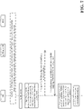
- a UE in RRC_CONNECTED will need to send a Sidelink UE Information message (e.g. SidelinkUEInformationNR) to gNB to request sidelink resources for transmitting sidelink traffic after a layer-2 link (or unicast link) has been established.
- gNB will then provide a dedicated sidelink configuration information (e.g. IE SL-ConfigDedicatedNR) for NR sidelink communication to the UE.
- SidelinkUEInformationNR may include the following information elements (IEs) related to the unicast link: sl-Destinationldentity, sl-CastType, sl-RLC_ModeIndication, sl-QoS-InfoList, sl-Failure, sl-TypeTxSyncList, and sl-TxInterestedFreqList.
- IEs information elements
- sl-QoS-InfoList contains a list of sl-QoS-Info, which is specified in TS 23.287 to include the QoS profile of a sidelink QoS flow, and each sl-QoS-Info includes sl-QoS-FlowIdentity and sl-QoS-Profile.
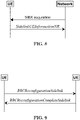
- gNB may reply with a RRC Connection Reconfiguration message (e.g. RRCReconfiguration ) to configure the dedicated sidelink configuration for the concerned sidelink QoS flow(s) identified by sl-QoS-FlowIdentity.
- RRC Connection Reconfiguration e.g. RRCReconfiguration
- RRCReconfiguration may include IE SL-ConfigDedicatedNR, which may contain information to indicate the dedicated sidelink configuration. It may also contain information to indicate to which SLRB (or SL LCH) a sidelink QoS flow is mapped (e.g. sl-MappedQoS-Flows).
- the sidelink QoS flow may be mapped to an existing SLRB or a new SLRB.
- a SLRB configuration e.g. sl-RadioBearerToAddModList
- a logical channel configuration e.g. sl-RLC-BearerToAddModList
- each SLRB is associated with a SL LCH.
- the initiating UE informs the peer UE of SLRB parameters that are related to both TX and RX and need to be aligned with the peer UE. For example, the initiating UE may transmit a RRCReconfigurationSidelink message to inform the peer UE (as discussed in the 3GPP email discussion [108#44][V2X] 38.331 running CR (Huawei)), wherein slrb-PC5-ConfigIndex is included in the RRCReconfigurationSidelink to indicate the SLRB configuration for a SLRB to be established in the peer UE. In response, the peer UE may replies with a RRCReconfigurationCompleteSidelink message.
- the peer UE shall report at least RLC mode indicated by the initiating UE to its gNB when the peer UE in RRC_CONNECTED receives an SLRB configuration with RLC AM/UM from the initiating UE and if the LCH has not been configured in the peer UE. It was also agreed that sidelink QoS profile is optional to be reported.
- the previous agreements were captured in the 3GPP email discussion [108#44][V2X] 38.331 running CR (Huawei), where the IE sl-QoS-InfoList defined in the SidelinkUEInformationNR message is specified as OPTIONAL.
- sl-QoS-InfoList If sl-QoS-InfoList is present, it means the peer UE has data available for transmission from the sidelink QoS flow identified by sl-QoS-FlowIdentity in sl-QoS-InfoList. Otherwise (i.e. sl-QoS-InfoList is absent), it means the peer UE has no data available for transmission from the sidelink QoS flow identified by sl-QoS-FlowIdentity in sl-QoS-InfoList. The latter case implies that the peer UE only has RLC Control PDU (for RLC AM mode) or PDCP Control PDU (for ROHC feedback) and thus there is no need include sl-QoS-InfoList. After receiving the SidelinkUEInformationNR message, gNB may then allocate a proper dedicated sidelink configuration to the peer UE according to whether sl-QoS-InfoList is present
- the initiating UE may transmit a RRCReconfigurationSidelink message to inform the peer UE (as discussed in the 3GPP email discussion [108#44][V2X] 38.331 running CR (Huawei)) to establish multiple SLRBs
- the peer UE needs to know which SLRB (or SL LCH) should be associated with the dedicated configuration information provided in the RRCReconfiguration by its gNB for the case where the peer UE has no data available for transmission from the concerned sidelink QoS flow mapped to the SLRB.
- the peer UE would not include sl-QoS-Info in sl-QoS-InfoList of the SidelinkUEInformationNR in case the peer UE has no traffic for transmission from a concerned sidelink QoS flow.
- gNB cannot include sl-MappedQoS-Flows in SL-RadioBearerConfig of the RRCReconfiguration since the SidelinkUEInformationNR does not include the sl-QoS-FlowIdentity.
- the peer UE does not know how to associate a SLRB (or a SL LCH) configured by the RRCReconfiguration with a SLRB (or a SL LCH) configured by the RRCReconfigurationSidelink.
- the RRCReconfigurationSidelink includes a first identity of a first sidelink QoS flow that is mapped to a first SL LCH using RLC AM for transmitting sidelink packets from the UE to the peer UE and a second identity of a second sidelink QoS flow that is mapped to a second SL LCH using RLC UM for transmitting sidelink packets from the UE to the peer UE. Since the peer UE currently has no traffic for transmission on the first or second SL LCHs, the peer UE still transmit SidelinkUEInformationNR to gNB but the SidelinkUEInformationNR does not report any sidelink QoS profile and/or sidelink QoS flow identity of the first/second sidelink QoS flows.
- gNB may transmit RRCReconfiguration including a first dedicated configuration information corresponding to the first SLRB or SL LCH and a second dedicated configuration information corresponding to the second SLRB or SL LCH to the peer UE.
- the peer UE is not able to associate which dedicated configuration information with which SLRB or SL LCH because the (first or second) dedicated configuration information includes neither the first identity of the first sidelink QoS flow nor the second identity of the second sidelink QoS flow. To address this issue, some solutions could be considered.
- the peer UE may include information related to the concerned SLRB (or SL LCH) in the SidelinkUEInformationNR so that its gNB can repeat the information in the RRCReconfiguration for the peer UE to know which SLRB (or SL LCH) should be associated with the dedicated configuration information.
- the information related to the concerned SLRB (or SL LCH) could be derived from RRCReconfigurationSidelink.
- the peer UE may include a slrb-PC5-ConfigIndex in the SidelinkUEInformationNR and then the gNB can provide a dedicated sidelink configuration for the slrb-PC5-ConfigIndex via the RRCReconfiguration.
- the peer UE may include a sl-LogicalChannelIdentity in the SidelinkUEInformationNR and then the gNB can provide a dedicated sidelink configuration for the sl-LogicalChannelIdentity via the RRCReconfiguration.
- the slrb-PC5-ConfigIndex or the sl-LogicalChannelIdentity is originally included in the RRCReconfigurationSidelink and is used to identify a SLRB (or SL LCH) configured for transmitting sidelink packets from the UE to the peer UE.
- the peer UE can know which SLRB (or SL LCH) should be associated with the dedicated sidelink configuration (e.g. IE SL-ConfigDedicatedNR ) provided by its gNB.
- the peer UE may include sl-QoS-FlowIdentity in sl-QoS-InfoList and does not include sl-QoS-Profile in sl-QoS-InfoList when transmitting the SidelinkUEInformationNR message to its gNB and then the gNB can provide a dedicated sidelink configuration for the sidelink QoS flow.
- the peer UE can also know which SLRB (or SL LCH) should be associated with the dedicated sidelink configuration (e.g. IE SL-ConfigDedicatedNR ) provided by its gNB because the sidelink QoS flow is mapped to the concerned SLRB (or SL LCH).
- This alternative may induce less change to the current RRC running CR (as discussed in the 3GPP email discussion [108#44][V2X] 38.331 running CR (Huawei)) as compared with the previous solution.
- the peer UE may receive the RRCReconfigurationSidelink from the UE.
- the RRCReconfigurationSidelink an identity of a sidelink QoS flow is mapped to a SLRB (or a SL LCH) for transmitting sidelink packets from the UE to the peer UE.
- the peer UE may transmit the SidelinkUEInformationNR to gNB.
- the SidelinkUEInformationNR the identity of the sidelink QoS flow is reported.
- the peer UE receives the RRCReconfiguration from gNB.
- a dedicated configuration information for configuring a SLRB (or a SL LCH) for transmitting sidelink packets from the peer UE to the UE is included.
- the identity of the sidelink QoS flow is included so that the peer UE knows the SLRB (or the SL LCH) configured by the dedicated configuration information should be associated with the SLRB (or the SL LCH) configured by the RRCReconfigurationSidelink.
- each dedicated configuration information without including sl-MappedQoS-Flows could be orderly associated with one SL-TxResourceReq without including SL-QoS-Info in SidelinkUEInformationNR message.
- the peer UE since the peer UE constructs a list of SL-TxResourceReq in the SidelinkUEInformationNR message by itself, the peer UE should know a SL-TxResourceReq not including SL-QoS-Info is associated with which one SLRB (or SL LCH) configured by RRCReconfigurationSidelink.
- the peer UE can know a dedicated configuration information without including sl-MappedQoS-Flows is associated with one SLRB (or SL LCH) for which no SL-QoS-Info is reported for this SLRB (or SL LCH).
- the UE may establish three SLRBs (or SL LCHs) for transmitting sidelink packets from the UE to the peer UE, one is a first SLRB using RLC AM, another is a second SLRB using RLC UM and the other is a third SLRB using RLC AM.
- the first SLRB is mapped to a sidelink QoS flow ID 1.
- the second SLRB is mapped to a sidelink QoS flow ID 2&3.
- the third SLRB is mapped to a sidelink QoS flow ID 4&5.
- the UE may transmit a RRCReconfigurationSidelink message to the peer UE, wherein the RRCReconfigurationSidelink message includes IEs for configuring these three SLRBs as shown in Table 1 below.
- the peer UE Upon reception of the RRCReconfigurationSidelink message, the peer UE transmits a SidelinkUEInformationNR message to gNB. At this moment, the peer UE may have traffic for transmission only on the sidelink QoS flows associated with PFI 2&3. Therefore, the peer UE only reports PFI 2&3 in the SidelinkUEInformationNR message.
- the PFI 2&3 could be reported via sl-UM-QoS-InfoList or sl-QoS-InfoList. There are two examples to report the PFI 2&3 in Table 2-1 and Table 2-2 separately.
- gNB Upon reception of the SidelinkUEInformationNR message, gNB responds a RRCReconfiguration message to the peer UE.
- gNB may include IEs in the RRCReconfiguration message in different ways.
- a first dedicated configuration information (SL-RadioBearerConfig #1 and SL-RLC-BearerConfig #1)
- a second dedicated configuration information (SL-RadioBearerConfig #2 and SL-RLC-BearerConfig #2)
- SL-RadioBearerConfig #3 and SL-RLC-BearerConfig #3) are included.
- the peer UE could associate the dedicated configuration information including PFIs 2&3 with SLRB2 because both a SL-QoS-FlowIdentity of sl-MappedQoS-Flows and a sl-QoS-FlowIdentity are mapped to SLRB2 (i.e. the SL-QoS-FlowIdentity in the sl-MappedQoS-Flows is the same as the sl-QoS-FlowIdentity).
- the peer UE associates the first dedicated configuration information with SLRB1 and associates the third dedicated configuration information with SLRB3.
- Table 3-1 of RRCReconfiguration Example 1 SL-RadioBearerConfig # sl-MappedQoS-Flows in sl-SDAP-Config of the SL-RadioBearerConfig SL-RLC-BearerConfig # SL-RLC-Config in the SL-RLC-BearerConfig MaxRetxThreshold in the SL-RLC-BearerConfig 1 Not present 1 sl-AM-RLC tl 2 PFI 2, 3 2 sl-UM-RLC N/A 3 Not present 3 sl-AM-RLC t3
- the peer UE associates the second dedicated configuration information with SLRB1 and associates the third dedicated configuration information with SLRB3.
- Table 3-2 of RRCReconfiguration Example 2 SL-RadioBearerConfig # sl-MappedQoS-Flows in sl-SDAP-Config of the SL-RadioBearerConfig SL-RLC-BearerConfig # SL-RLC-Config in the SL-RLC-BearerConfig MaxRetxThreshold in the SL-RLC-BearerConfig 1 PFI 2, 3 1 sl-UM-RLC N/A 2 Not present 2 sl-AM-RLC tl 3 Not present 3 sl-AM-RLC t3
- the peer UE associates the first dedicated configuration information with SLRB1 and associates the second dedicated configuration information with SLRB3.
- Table 3-3 of RRCReconfiguration Example 3 SL-RadioBearerConfig # sl-MappedQoS-Flows in sl-SDAP-Config of the SL-RadioBearerConfig SL-RLC-BearerConfig # SL-RLC-Config in the SL-RLC-BearerConfig MaxRetxThreshold in the SL-RLC-BearerConfig 1 Not present 1 sl-AM-RLC t1 2 Not present 2 sl-AM-RLC t3 3 PFI 2, 3 3 sl-UM-RLC N/A
- FIG. 12 is a flow chart 1200 according to one exemplary embodiment from the perspective of a first UE to request dedicated sidelink configuration.
- the first UE transmits a first RRC message to a network node, wherein the first RRC message includes a sidelink QoS information, and wherein a presence of an identity of a sidelink QoS flow in the sidelink QoS information is mandatory and a presence of a QoS profile of the sidelink QoS flow in the sidelink QoS information is optional.
- the first UE receives a second RRC message from the network node, wherein the second RRC message includes a dedicated sidelink configuration and the identity of the sidelink QoS flow associated with the dedicated sidelink configuration, wherein the sidelink QoS information includes the identity of the sidelink QoS flow if there is no data available for transmission form the sidelink QoS flow.
- the sidelink QoS information may not include any QoS profile of the sidelink QoS flow if there is no data available for transmission from the sidelink QoS flow.
- the sidelink QoS information may include the identity of the sidelink QoS flow, and may also include the QoS profile of the sidelink QoS flow if there is data available for transmission from the sidelink QoS flow.
- the first UE may receive a first sidelink RRC message from a second UE before transmitting the first RRC message to the network node.
- the first sidelink RRC message may include a SLRB configuration for reception, an index to the SLRB configuration (e.g. slrb-PC5-ConfigIndex ) , and/or a logical channel configuration.
- the first sidelink RRC message could be a RRCReconfigurationSidelink message.
- the first UE may associate a counter SLRB configured by the dedicated sidelink configuration with a SLRB configured by the first sidelink RRC message according to the identity of the sidelink QoS flow.
- the SLRB may be used for transmitting packets from the second UE to the first UE, and the counter SLRB is used for transmitting packets from the first UE to the second UE.
- the first RRC message could be a SidelinkUEInformationNR message
- the second RRC message could be a RRCReconfiguration message.
- the network node could be a base station (e.g. gNB).
- gNB base station
- the first UE 300 includes a program code 312 stored in the memory 310.
- the CPU 308 could execute program code 312 to enable the first UE (i) to transmit a first RRC message to a network node, wherein the first RRC message includes a sidelink QoS information, and wherein a presence of an identity of a sidelink QoS flow in the sidelink QoS information is mandatory and a presence of a QoS profile of the sidelink QoS flow in the sidelink QoS information is optional, and (ii) to receive a second RRC message from the network node, wherein the second RRC message includes a dedicated sidelink configuration and the identity of the sidelink QoS flow associated with the dedicated sidelink configuration.
- the CPU 308 can execute the program code 312 to perform all of the above-described actions and steps or others described herein.
- FIG. 13 is a flow chart 1300 from the perspective of a first UE to request dedicated sidelink configuration.
- the first UE transmits a first RRC message to a network node, wherein the first RRC message includes a sidelink QoS Info and wherein the sidelink QoS Info includes an identity of a sidelink QoS flow and does not include any QoS profile of the sidelink QoS flow.
- the first UE receives a second RRC message from the network node, wherein the second RRC message includes a dedicated sidelink configuration and the identity of the sidelink QoS flow associated with the dedicated sidelink configuration.
- the sidelink QoS Info may include the identity of the sidelink QoS flow, and may not include any QoS profile of the sidelink QoS flow if there is no data available for transmission from the sidelink QoS flow.
- the sidelink QoS Info may include the identity of the sidelink QoS flow, and may also include a QoS profile of the sidelink QoS flow if there is data available for transmission from the sidelink QoS flow.
- the first RRC message may include a destination identity (e.g. Destination Layer-2 ID), a cast type, RLC Mode indication, and/or a frequency.
- the second RRC message may include a resource allocation mode, a SLRB configuration for transmission, and/or a logical channel configuration.
- the first UE could receive a first sidelink RRC message from a second UE before transmitting the first RRC message. Furthermore, the first UE could transmit the first RRC message in response to reception of the first sidelink RRC message from the second UE.
- the first sidelink RRC message may include a SLRB configuration for reception, an index to the SLRB configuration (e.g. slrb-PC5-ConfigIndex ) , and/or a logical channel configuration.
- the first UE could reply with a second sidelink RRC message to the second UE.
- the first RRC message may be a SidelinkUEInformationNR message.
- the second RRC message may be a RRCReconfiguration message.
- the first sidelink RRC message may be a RRCReconfigurationSidelink message.
- the second sidelink RRC message may be a RRCReconfigurationCompleteSidelink message.
- the network node could be a base station (e.g. gNB).
- gNB base station
- the first UE 300 includes a program code 312 stored in the memory 310.
- the CPU 308 could execute program code 312 to enable the first UE (i) to transmit a first RRC message to a network node, wherein the first RRC message includes a sidelink QoS Info and wherein the sidelink QoS Info includes an identity of a sidelink QoS flow and does not include any QoS profile of the sidelink QoS flow, and (ii) to receive a second RRC message from the network node, wherein the second RRC message includes a dedicated sidelink configuration and the identity of the sidelink QoS flow associated with the dedicated sidelink configuration.
- the CPU 308 can execute the program code 312 to perform all of the above-described actions and steps or others described herein.
- FIG. 14 is a flow chart 1400 from the perspective of a first UE to request Sidelink Radio Bearer (SLRB) configuration.
- the first UE transmits a first RRC message to a network node, wherein the first RRC message includes a list of transmission resource request for requesting one or more SLRB configurations, and each entry in the list of transmission resource request has at least one IE for sidelink QoS information.
- the first UE receives a second RRC message from the network node, wherein the second RRC message includes the one or more SLRB configurations.
- the first UE corresponds each SLRB configuration not associated with any sidelink QoS flow identity in the second RRC message to one entry not indicating any sidelink QoS information in the list of transmission resource request in the first RRC message in sequence.
- the first UE transmits sidelink control packet on a SL LCH to a second UE based on a SLRB configuration in the second RRC message.
- each entry in the list of transmission resource request also has one IE for RLC mode indication.
- the first UE could receive a PC5 RRC message from the second UE, wherein the PC5 RRC message indicates establishment of a first SLRB (or a first SL LCH) using a first LCID and a RLC mode, and the first SLRB is mapped to a first sidelink QoS flow associated with a first PFI and/or a first sidelink QoS profile.
- the PC5 RRC message may also indicate establishment of a second SLRB (or a second SL LCH) using a second LCID and a RLC mode, and the second SLRB is mapped to a second sidelink QoS flow associated with a second PFI and/or a second sidelink QoS profile.
- a first entry of the list of transmission resource request may indicate the RLC mode of the first SLRB, but may not include the first PFI and/or the first sidelink QoS profile.
- a second entry of the list of transmission resource request may indicate the RLC mode of the second SLRB, but may not include the second PFI and/or the second sidelink QoS profile.
- the second RRC message may include a first SLRB configuration not associated with any PFI and a second SLRB configuration not associated with any PFI in-sequence.
- a first entry may be the very first entry in the list of transmission resource request that may indicate one RLC mode of one SLRB, but may not include any PFI and/or any sidelink QoS profile.
- the second entry may be an entry following the very first entry in the list of transmission resource request that may indicate one RLC mode of one SLRB, but may not include any PFI and/or any sidelink QoS profile.
- the first SLRB configuration could be the very first SLRB configuration in the second RRC message that may indicate any PFI associated with this SLRB configuration.
- the second SLRB configuration could be a SLRB configuration following the very first SLRB configuration in the second RRC message that may not indicate any PFI associated with this SLRB configuration.
- the first UE could transmit one or more sidelink control packets on one SL LCH associated with the first LCID based on the first SLRB configuration.
- the first UE could also transmit one or more sidelink control packets on one SL LCH associated with the second LCID based on the second SLRB configuration.
- the first RRC message may be a SidelinkUEInformationNR message.
- the second RRC message may be a RRCReconfiguration message.
- the PC5 RRC message may be a RRCReconfigurationSidelink message.
- the sidelink control packet may be a RLC status report or a RoHC feedback.
- the sidelink QoS information may include a sidelink or PC5 QoS flow identity (PFI) and/or a sidelink QoS profile for a sidelink QoS flow.
- PFI PC5 QoS flow identity
- the network node could be a base station (e.g. gNB).
- gNB base station
- the first UE 300 includes a program code 312 stored in the memory 310.
- the CPU 308 could execute program code 312 to enable the first UE (i) to transmit a first RRC message to a network node, wherein the first RRC message includes a list of transmission resource request for requesting one or more SLRB configurations, and each entry in the list of transmission resource request has at least one IE for sidelink QoS information, (ii) to receive a second RRC message from the network node, wherein the second RRC message includes the one or more SLRB configurations, (iii) to correspond each SLRB configuration not associated with any sidelink QoS flow identity in the second RRC message to one entry not indicating any sidelink QoS information in the list of transmission resource request in the first RRC message in sequence, and (iv) to transmit sidelink control packet on a SL LCH to a second UE based on
- FIG. 15 is a flow chart 1500 according to one exemplary embodiment from the perspective of a network node to assign dedicated sidelink configuration.
- the network node receives a first RRC message from a first UE, wherein the first RRC message includes a sidelink QoS information, and wherein a presence of an identity of a sidelink QoS flow in the sidelink QoS information is mandatory and a presence of a QoS profile of the sidelink QoS flow in the sidelink QoS information is optional.
- the network node transmits a second RRC message to the first UE, wherein the second RRC message includes a dedicated sidelink configuration and the identity of the sidelink QoS flow associated with the dedicated sidelink configuration, wherein the sidelink QoS information includes the identity of the sidelink QoS flow if there is no data available for transmission form the sidelink QoS flow.
- the sidelink QoS information may not include any QoS profile of the sidelink QoS flow if there is no data available in the first UE for transmission from the sidelink QoS flow.
- the sidelink QoS information may include the identity of the sidelink QoS flow, and may also include the QoS profile of the sidelink QoS flow if there is data available in the first UE for transmission from the sidelink QoS flow.
- the first RRC message may be a SidelinkUEInformationNR message
- the second RRC message is a RRCReconfiguration message.
- the network node could be a base station (e.g. gNB).
- gNB base station
- the network node 300 includes a program code 312 stored in the memory 310.
- the CPU 308 could execute program code 312 to enable the network node (i) to receive a first RRC message from a first UE, wherein the first RRC message includes a sidelink QoS information, and wherein a presence of an identity of a sidelink QoS flow in the sidelink QoS information is mandatory and a presence of a QoS profile of the sidelink QoS flow in the sidelink QoS information is optional, and (ii) to transmit a second RRC message to the first UE, wherein the second RRC message includes a dedicated sidelink configuration and the identity of the sidelink QoS flow associated with the dedicated sidelink configuration.
- the CPU 308 can execute the program code 312 to perform all of the above-described actions and steps or others described herein.
- concurrent channels could be established based on pulse repetition frequencies.
- concurrent channels could be established based on pulse position or offsets.
- concurrent channels could be established based on time hopping sequences.
- concurrent channels could be established based on pulse repetition frequencies, pulse positions or offsets, and time hopping sequences.
- the various illustrative logical blocks, modules, and circuits described in connection with the aspects disclosed herein may be implemented within or performed by an integrated circuit ("IC"), an access terminal, or an access point.
- the IC may comprise a general purpose processor, a digital signal processor (DSP), an application specific integrated circuit (ASIC), a field programmable gate array (FPGA) or other programmable logic device, discrete gate or transistor logic, discrete hardware components, electrical components, optical components, mechanical components, or any combination thereof designed to perform the functions described herein, and may execute codes or instructions that reside within the IC, outside of the IC, or both.
- a general purpose processor may be a microprocessor, but in the alternative, the processor may be any conventional processor, controller, microcontroller, or state machine.
- a processor may also be implemented as a combination of computing devices, e.g., a combination of a DSP and a microprocessor, a plurality of microprocessors, one or more microprocessors in conjunction with a DSP core, or any other such configuration.
- a software module e.g., including executable instructions and related data
- other data may reside in a data memory such as RAM memory, flash memory, ROM memory, EPROM memory, EEPROM memory, registers, a hard disk, a removable disk, a CD-ROM, or any other form of computer-readable storage medium known in the art.
- a sample storage medium may be coupled to a machine such as, for example, a computer/processor (which may be referred to herein, for convenience, as a "processor") such the processor can read information (e.g., code) from and write information to the storage medium.
- a sample storage medium may be integral to the processor.
- the processor and the storage medium may reside in an ASIC.
- the ASIC may reside in user equipment.
- the processor and the storage medium may reside as discrete components in user equipment.
- any suitable computer-program product may comprise a computer-readable medium comprising codes relating to one or more of the aspects of the disclosure.
- a computer program product may comprise packaging materials.
Claims (15)
- Procédé permettant à un premier Équipement Utilisateur, également appelé dans ce qui suit UE, de demander une configuration de liaison latérale dédiée, comprenant :la transmission d'un premier message de Commande de Ressources Radio, également appelée dans ce qui suit RRC, à un nœud de réseau, dans lequel le premier message RRC comprend des informations (1205) de Qualité de Service, également appelée dans ce qui suit QoS, de liaison latérale ; etla réception d'un deuxième message RRC du nœud de réseau, dans lequel le deuxième message RRC comprend une configuration de liaison latérale dédiée et une identité d'un flux QoS de liaison latérale associée à la configuration de liaison latérale dédiée (1210),caractérisé en ce quela présence de l'identité du flux QoS de liaison latérale dans les informations QoS de liaison latérale est obligatoire et la présence d'un profil QoS du flux QoS de liaison latérale dans les informations QoS de liaison latérale est facultative, dans lequel les informations QoS de liaison latérale comprennent l'identité du flux QoS de liaison latérale s'il n'y a pas de données disponibles pour la transmission à partir du flux QoS de liaison latérale.
- Procédé de la revendication 1, dans lequel les informations QoS de liaison latérale ne comprennent aucun profil QoS du flux QoS de liaison latérale s'il n'y a pas de données disponibles pour la transmission à partir du flux QoS de liaison latérale.
- Procédé de la revendication 1 ou 2, dans lequel les informations QoS de liaison latérale comprennent l'identité du flux QoS de liaison latérale et comprennent également le profil QoS du flux QoS de liaison latérale s'il y a des données disponibles pour la transmission à partir du flux QoS de liaison latérale.
- Procédé de l'une quelconque des revendications 1 à 3, comprenant en outre :
la réception d'un premier message RRC de liaison latérale d'un deuxième UE avant de transmettre le premier message RRC au nœud de réseau. - Procédé de la revendication 4, dans lequel le premier message RRC de liaison latérale comprend une configuration de Porteuse Radio de Liaison Latérale, également appelée dans ce qui suit SLRB, pour la réception, un indice de la configuration SLRB et/ou une configuration de canal logique.
- Procédé de la revendication 4 ou 5, dans lequel le premier message RRC de liaison latérale est un message RRCReconfigurationSidelink.
- Procédé de l'une quelconque des revendications 4 à 6, comprenant en outre :
l'association d'une SLRB de compteur configurée par la configuration de liaison latérale dédiée à une SLRB configurée par le premier message RRC de liaison latérale selon l'identité du flux QoS de liaison latérale. - Procédé de la revendication 7, dans lequel la SLRB est utilisée pour transmettre des paquets du deuxième UE au premier UE, et la SLRB de compteur est utilisée pour transmettre des paquets du premier UE au deuxième UE.
- Procédé de l'une quelconque des revendications 1 à 8, dans lequel le premier message RRC est un message SidelinkUEInformationNR, et le deuxième message RRC est un message RRCReconfiguration ; et/ou
dans lequel le nœud de réseau est une station de base. - Premier Équipement Utilisateur, également appelé dans ce qui suit UE, comprenant :un circuit de commande (306) ;un processeur (308) installé dans le circuit de commande (306) ; etune mémoire (310) installée dans le circuit de commande (306) et couplée de manière fonctionnelle au processeur (308) ;caractérisé en ce que le processeur (308) est configuré pour exécuter un code de programme (312) stocké dans la mémoire (310) pour réaliser les étapes de procédé telles que définies dans l'une quelconque des revendications précédentes.
- Procédé permettant à un nœud de réseau d'attribuer une configuration de liaison latérale dédiée, comprenant :la réception d'un premier message de Commande de Ressources Radio, également appelée dans ce qui suit RRC, d'un premier Équipement Utilisateur, également appelé dans ce qui suit UE, dans lequel le premier message RRC comprend des informations (1505) de Qualité de Service, également appelée dans ce qui suit QoS, de liaison latérale ; etla transmission d'un deuxième message RRC au premier UE, dans lequel le deuxième message RRC comprend une configuration de liaison latérale dédiée et une identité d'un flux QoS de liaison latérale associée à la configuration de liaison latérale dédiée (1510),caractérisé en ce quela présence de l'identité du flux QoS de liaison latérale dans les informations QoS de liaison latérale est obligatoire et la présence d'un profil QoS du flux QoS de liaison latérale dans les informations QoS de liaison latérale est facultative, dans lequel les informations QoS de liaison latérale comprennent l'identité du flux QoS de liaison latérale s'il n'y a pas de données disponibles pour la transmission à partir du flux QoS de liaison latérale.
- Procédé de la revendication 11, dans lequel les informations QoS de liaison latérale ne comprennent aucun profil QoS du flux QoS de liaison latérale s'il n'y a pas de données disponibles dans le premier UE pour la transmission à partir du flux QoS de liaison latérale.
- Procédé de la revendication 11 ou 12, dans lequel les informations QoS de liaison latérale comprennent l'identité du flux QoS de liaison latérale et comprennent également le profil QoS du flux QoS de liaison latérale s'il y a des données disponibles dans le premier UE pour la transmission à partir du flux QoS de liaison latérale.
- Procédé de l'une quelconque des revendications 11 à 13, dans lequel le premier message RRC est un message SidelinkUEInformationNR, et le deuxième message RRC est un message RRCReconfiguration ; et/ou
dans lequel le nœud de réseau est une station de base. - Nœud de réseau, comprenant :un circuit de commande (306) ;un processeur (308) installé dans le circuit de commande (306) ; etune mémoire (310) installée dans le circuit de commande (306) et couplée de manière fonctionnelle au processeur (308) ;caractérisé en ce que le processeur (308) est configuré pour exécuter un code de programme (312) stocké dans la mémoire (310) pour réaliser les étapes de procédé telles que définies dans l'une quelconque des revendications précédentes 11 à 14.
Applications Claiming Priority (1)
| Application Number | Priority Date | Filing Date | Title |
|---|---|---|---|
| US202062958061P | 2020-01-07 | 2020-01-07 |
Publications (2)
| Publication Number | Publication Date |
|---|---|
| EP3849237A1 EP3849237A1 (fr) | 2021-07-14 |
| EP3849237B1 true EP3849237B1 (fr) | 2022-09-21 |
Family
ID=73834203
Family Applications (1)
| Application Number | Title | Priority Date | Filing Date |
|---|---|---|---|
| EP20213312.0A Active EP3849237B1 (fr) | 2020-01-07 | 2020-12-11 | Procédé et appareil permettant de demander des ressources de transmission de liaison latérale dans un système de communication sans fil |
Country Status (7)
| Country | Link |
|---|---|
| US (2) | US11071006B1 (fr) |
| EP (1) | EP3849237B1 (fr) |
| JP (1) | JP6997852B2 (fr) |
| KR (1) | KR102266530B1 (fr) |
| CN (1) | CN113163454B (fr) |
| ES (1) | ES2932964T3 (fr) |
| TW (1) | TWI742962B (fr) |
Families Citing this family (4)
| Publication number | Priority date | Publication date | Assignee | Title |
|---|---|---|---|---|
| JP7033173B2 (ja) * | 2019-08-02 | 2022-03-09 | 華碩電腦股▲ふん▼有限公司 | ワイヤレス通信システムにおけるサイドリンク無線ベアラを解放するための方法及び装置 |
| CN113079712A (zh) * | 2019-11-04 | 2021-07-06 | 苹果公司 | 双向侧链路无线电链路控制承载 |
| CN116033601B (zh) * | 2021-10-25 | 2024-02-13 | 华硕电脑股份有限公司 | 中继用户设备侧链路无线电链路控制承载配置方法和设备 |
| KR20240011439A (ko) * | 2022-07-19 | 2024-01-26 | 삼성전자주식회사 | 무선 통신 시스템에서 두 원격 단말 간의 릴레이 단말을 통한 중계 통신을 관리하는 방법 및 장치 |
Family Cites Families (10)
| Publication number | Priority date | Publication date | Assignee | Title |
|---|---|---|---|---|
| US9301191B2 (en) * | 2013-09-20 | 2016-03-29 | Telecommunication Systems, Inc. | Quality of service to over the top applications used with VPN |
| CN102448053B (zh) * | 2010-09-30 | 2015-08-26 | 上海贝尔股份有限公司 | 在回程链路上执行多个mac pdu传递的方法和中继节点 |
| US9942917B2 (en) * | 2015-05-14 | 2018-04-10 | Blackberry Limited | Allocating resources for a device-to-device transmission |
| WO2018004322A1 (fr) * | 2016-07-01 | 2018-01-04 | 엘지전자(주) | Procédé d'émission et de réception de données dans un système de communication sans fil et appareil associé |
| US20180324631A1 (en) * | 2017-05-05 | 2018-11-08 | Mediatek Inc. | Using sdap headers for handling of as/nas reflective qos and to ensure in-sequence packet delivery during remapping in 5g communication systems |
| CN109392023B (zh) * | 2017-08-10 | 2023-11-14 | 北京三星通信技术研究有限公司 | 一种数据流的操作控制的方法及设备 |
| EP3815450A1 (fr) | 2018-06-28 | 2021-05-05 | Convida Wireless, Llc | Procédures de priorisation pour une transmission de données de canal partagé de liaison latérale nr v2x |
| CN110831075A (zh) | 2018-08-10 | 2020-02-21 | 中兴通讯股份有限公司 | 数据传输方法及装置,业务切换方法及装置 |
| KR20200094343A (ko) * | 2019-01-30 | 2020-08-07 | 삼성전자주식회사 | 무선 통신 시스템에서 직접 통신 베어러의 서비스 품질을 관리 및 설정하는 장치 및 방법 |
| US11147080B2 (en) * | 2019-11-13 | 2021-10-12 | Asustek Computer Inc. | Method and apparatus for requesting sidelink transmission resources in a wireless communication system |
-
2020
- 2020-12-11 KR KR1020200173643A patent/KR102266530B1/ko active IP Right Grant
- 2020-12-11 ES ES20213312T patent/ES2932964T3/es active Active
- 2020-12-11 US US17/119,486 patent/US11071006B1/en active Active
- 2020-12-11 JP JP2020205568A patent/JP6997852B2/ja active Active
- 2020-12-11 TW TW109143980A patent/TWI742962B/zh active
- 2020-12-11 CN CN202011458356.1A patent/CN113163454B/zh active Active
- 2020-12-11 EP EP20213312.0A patent/EP3849237B1/fr active Active
-
2021
- 2021-06-18 US US17/352,230 patent/US20220132359A1/en not_active Abandoned
Also Published As
| Publication number | Publication date |
|---|---|
| US20210211924A1 (en) | 2021-07-08 |
| KR102266530B1 (ko) | 2021-06-18 |
| TWI742962B (zh) | 2021-10-11 |
| US20220132359A1 (en) | 2022-04-28 |
| US11071006B1 (en) | 2021-07-20 |
| CN113163454B (zh) | 2022-05-03 |
| TW202127944A (zh) | 2021-07-16 |
| EP3849237A1 (fr) | 2021-07-14 |
| JP2021111967A (ja) | 2021-08-02 |
| CN113163454A (zh) | 2021-07-23 |
| ES2932964T3 (es) | 2023-01-30 |
| JP6997852B2 (ja) | 2022-01-18 |
Similar Documents
| Publication | Publication Date | Title |
|---|---|---|
| EP3823410B1 (fr) | Procédé et appareil permettant de demander des ressources de transmission de liaison latérale dans un système de communication sans fil | |
| US11665765B2 (en) | Method and apparatus for configuring sidelink communication in a wireless communication system | |
| US11589254B2 (en) | Method and apparatus for requesting sidelink radio bearer (SLRB) configuration of unicast transmission in a wireless communication system | |
| EP3849237B1 (fr) | Procédé et appareil permettant de demander des ressources de transmission de liaison latérale dans un système de communication sans fil | |
| US10952230B1 (en) | Method and apparatus for supporting QOS (quality of service) flow to DRB (data radio bearer) remapping for sidelink communication in a wireless communication system | |
| CN112312570B (zh) | 无线通信系统中用于释放侧链路无线电承载的方法和设备 | |
| US20210259039A1 (en) | Method and apparatus for handling invalid rrc reconfiguration message for sidelink communication in a wireless communication system | |
| KR102432230B1 (ko) | 무선 통신 시스템에서 사이드링크 사용자 단말(ue) 성능 정보를 포워딩하기 위한 방법 및 장치 | |
| EP3787368B1 (fr) | Procédé et appareil de configuration de compression d'en-tête pour une porteuse radio de liaison latérale dans un système de communication sans fil | |
| EP3829260B1 (fr) | Procédé et appareil d'établissement de porteuse radio de signalisation (srb) de liaison latérale dans un système de communication sans fil | |
| KR20220001452A (ko) | 무선 통신 시스템에서 릴레이가 사이드링크 사용자 단말(ue) 성능 정보를 보고하기 위한 방법 및 장치 | |
| US11638197B1 (en) | Method and apparatus for supporting UE-to-network relay communication in a wireless communication system | |
| US11665769B2 (en) | Method and apparatus for supporting UE-to-network relay communication in a wireless communication system | |
| KR20230105643A (ko) | 무선 통신 시스템에서 릴레이 ue를 통해 다른 원격 사용자 단말(ue)과 연결하기 위한 방법 및 장치 | |
| CN117998524A (zh) | 用于支持ue间中继通信中的层2链路修改的方法和设备 |
Legal Events
| Date | Code | Title | Description |
|---|---|---|---|
| PUAI | Public reference made under article 153(3) epc to a published international application that has entered the european phase |
Free format text: ORIGINAL CODE: 0009012 |
|
| STAA | Information on the status of an ep patent application or granted ep patent |
Free format text: STATUS: THE APPLICATION HAS BEEN PUBLISHED |
|
| AK | Designated contracting states |
Kind code of ref document: A1 Designated state(s): AL AT BE BG CH CY CZ DE DK EE ES FI FR GB GR HR HU IE IS IT LI LT LU LV MC MK MT NL NO PL PT RO RS SE SI SK SM TR |
|
| STAA | Information on the status of an ep patent application or granted ep patent |
Free format text: STATUS: REQUEST FOR EXAMINATION WAS MADE |
|
| 17P | Request for examination filed |
Effective date: 20210818 |
|
| RBV | Designated contracting states (corrected) |
Designated state(s): AL AT BE BG CH CY CZ DE DK EE ES FI FR GB GR HR HU IE IS IT LI LT LU LV MC MK MT NL NO PL PT RO RS SE SI SK SM TR |
|
| STAA | Information on the status of an ep patent application or granted ep patent |
Free format text: STATUS: EXAMINATION IS IN PROGRESS |
|
| 17Q | First examination report despatched |
Effective date: 20211029 |
|
| GRAP | Despatch of communication of intention to grant a patent |
Free format text: ORIGINAL CODE: EPIDOSNIGR1 |
|
| STAA | Information on the status of an ep patent application or granted ep patent |
Free format text: STATUS: GRANT OF PATENT IS INTENDED |
|
| RIC1 | Information provided on ipc code assigned before grant |
Ipc: H04W 72/08 20090101ALN20220224BHEP Ipc: H04W 28/24 20090101AFI20220224BHEP |
|
| REG | Reference to a national code |
Ref country code: HK Ref legal event code: DE Ref document number: 40056734 Country of ref document: HK |
|
| INTG | Intention to grant announced |
Effective date: 20220318 |
|
| GRAS | Grant fee paid |
Free format text: ORIGINAL CODE: EPIDOSNIGR3 |
|
| RIN1 | Information on inventor provided before grant (corrected) |
Inventor name: KUO, RICHARD LEE-CHEE Inventor name: PAN, LI-TE |
|
| GRAA | (expected) grant |
Free format text: ORIGINAL CODE: 0009210 |
|
| STAA | Information on the status of an ep patent application or granted ep patent |
Free format text: STATUS: THE PATENT HAS BEEN GRANTED |
|
| AK | Designated contracting states |
Kind code of ref document: B1 Designated state(s): AL AT BE BG CH CY CZ DE DK EE ES FI FR GB GR HR HU IE IS IT LI LT LU LV MC MK MT NL NO PL PT RO RS SE SI SK SM TR |
|
| REG | Reference to a national code |
Ref country code: GB Ref legal event code: FG4D |
|
| REG | Reference to a national code |
Ref country code: CH Ref legal event code: EP |
|
| REG | Reference to a national code |
Ref country code: IE Ref legal event code: FG4D |
|
| REG | Reference to a national code |
Ref country code: DE Ref legal event code: R096 Ref document number: 602020005234 Country of ref document: DE |
|
| REG | Reference to a national code |
Ref country code: AT Ref legal event code: REF Ref document number: 1520577 Country of ref document: AT Kind code of ref document: T Effective date: 20221015 |
|
| REG | Reference to a national code |
Ref country code: NL Ref legal event code: FP |
|
| REG | Reference to a national code |
Ref country code: LT Ref legal event code: MG9D |
|
| REG | Reference to a national code |
Ref country code: ES Ref legal event code: FG2A Ref document number: 2932964 Country of ref document: ES Kind code of ref document: T3 Effective date: 20230130 |
|
| PG25 | Lapsed in a contracting state [announced via postgrant information from national office to epo] |
Ref country code: SE Free format text: LAPSE BECAUSE OF FAILURE TO SUBMIT A TRANSLATION OF THE DESCRIPTION OR TO PAY THE FEE WITHIN THE PRESCRIBED TIME-LIMIT Effective date: 20220921 Ref country code: RS Free format text: LAPSE BECAUSE OF FAILURE TO SUBMIT A TRANSLATION OF THE DESCRIPTION OR TO PAY THE FEE WITHIN THE PRESCRIBED TIME-LIMIT Effective date: 20220921 Ref country code: NO Free format text: LAPSE BECAUSE OF FAILURE TO SUBMIT A TRANSLATION OF THE DESCRIPTION OR TO PAY THE FEE WITHIN THE PRESCRIBED TIME-LIMIT Effective date: 20221221 Ref country code: LV Free format text: LAPSE BECAUSE OF FAILURE TO SUBMIT A TRANSLATION OF THE DESCRIPTION OR TO PAY THE FEE WITHIN THE PRESCRIBED TIME-LIMIT Effective date: 20220921 Ref country code: LT Free format text: LAPSE BECAUSE OF FAILURE TO SUBMIT A TRANSLATION OF THE DESCRIPTION OR TO PAY THE FEE WITHIN THE PRESCRIBED TIME-LIMIT Effective date: 20220921 Ref country code: FI Free format text: LAPSE BECAUSE OF FAILURE TO SUBMIT A TRANSLATION OF THE DESCRIPTION OR TO PAY THE FEE WITHIN THE PRESCRIBED TIME-LIMIT Effective date: 20220921 |
|
| REG | Reference to a national code |
Ref country code: AT Ref legal event code: MK05 Ref document number: 1520577 Country of ref document: AT Kind code of ref document: T Effective date: 20220921 |
|
| PG25 | Lapsed in a contracting state [announced via postgrant information from national office to epo] |
Ref country code: HR Free format text: LAPSE BECAUSE OF FAILURE TO SUBMIT A TRANSLATION OF THE DESCRIPTION OR TO PAY THE FEE WITHIN THE PRESCRIBED TIME-LIMIT Effective date: 20220921 Ref country code: GR Free format text: LAPSE BECAUSE OF FAILURE TO SUBMIT A TRANSLATION OF THE DESCRIPTION OR TO PAY THE FEE WITHIN THE PRESCRIBED TIME-LIMIT Effective date: 20221222 |
|
| PG25 | Lapsed in a contracting state [announced via postgrant information from national office to epo] |
Ref country code: SM Free format text: LAPSE BECAUSE OF FAILURE TO SUBMIT A TRANSLATION OF THE DESCRIPTION OR TO PAY THE FEE WITHIN THE PRESCRIBED TIME-LIMIT Effective date: 20220921 Ref country code: RO Free format text: LAPSE BECAUSE OF FAILURE TO SUBMIT A TRANSLATION OF THE DESCRIPTION OR TO PAY THE FEE WITHIN THE PRESCRIBED TIME-LIMIT Effective date: 20220921 Ref country code: PT Free format text: LAPSE BECAUSE OF FAILURE TO SUBMIT A TRANSLATION OF THE DESCRIPTION OR TO PAY THE FEE WITHIN THE PRESCRIBED TIME-LIMIT Effective date: 20230123 Ref country code: CZ Free format text: LAPSE BECAUSE OF FAILURE TO SUBMIT A TRANSLATION OF THE DESCRIPTION OR TO PAY THE FEE WITHIN THE PRESCRIBED TIME-LIMIT Effective date: 20220921 Ref country code: AT Free format text: LAPSE BECAUSE OF FAILURE TO SUBMIT A TRANSLATION OF THE DESCRIPTION OR TO PAY THE FEE WITHIN THE PRESCRIBED TIME-LIMIT Effective date: 20220921 |
|
| PGFP | Annual fee paid to national office [announced via postgrant information from national office to epo] |
Ref country code: ES Payment date: 20230117 Year of fee payment: 3 |
|
| PG25 | Lapsed in a contracting state [announced via postgrant information from national office to epo] |
Ref country code: SK Free format text: LAPSE BECAUSE OF FAILURE TO SUBMIT A TRANSLATION OF THE DESCRIPTION OR TO PAY THE FEE WITHIN THE PRESCRIBED TIME-LIMIT Effective date: 20220921 Ref country code: PL Free format text: LAPSE BECAUSE OF FAILURE TO SUBMIT A TRANSLATION OF THE DESCRIPTION OR TO PAY THE FEE WITHIN THE PRESCRIBED TIME-LIMIT Effective date: 20220921 Ref country code: IS Free format text: LAPSE BECAUSE OF FAILURE TO SUBMIT A TRANSLATION OF THE DESCRIPTION OR TO PAY THE FEE WITHIN THE PRESCRIBED TIME-LIMIT Effective date: 20230121 Ref country code: EE Free format text: LAPSE BECAUSE OF FAILURE TO SUBMIT A TRANSLATION OF THE DESCRIPTION OR TO PAY THE FEE WITHIN THE PRESCRIBED TIME-LIMIT Effective date: 20220921 |
|
| PGFP | Annual fee paid to national office [announced via postgrant information from national office to epo] |
Ref country code: IT Payment date: 20221231 Year of fee payment: 3 |
|
| P01 | Opt-out of the competence of the unified patent court (upc) registered |
Effective date: 20230428 |
|
| REG | Reference to a national code |
Ref country code: DE Ref legal event code: R097 Ref document number: 602020005234 Country of ref document: DE |
|
| PG25 | Lapsed in a contracting state [announced via postgrant information from national office to epo] |
Ref country code: AL Free format text: LAPSE BECAUSE OF FAILURE TO SUBMIT A TRANSLATION OF THE DESCRIPTION OR TO PAY THE FEE WITHIN THE PRESCRIBED TIME-LIMIT Effective date: 20220921 |
|
| PLBE | No opposition filed within time limit |
Free format text: ORIGINAL CODE: 0009261 |
|
| STAA | Information on the status of an ep patent application or granted ep patent |
Free format text: STATUS: NO OPPOSITION FILED WITHIN TIME LIMIT |
|
| PG25 | Lapsed in a contracting state [announced via postgrant information from national office to epo] |
Ref country code: DK Free format text: LAPSE BECAUSE OF FAILURE TO SUBMIT A TRANSLATION OF THE DESCRIPTION OR TO PAY THE FEE WITHIN THE PRESCRIBED TIME-LIMIT Effective date: 20220921 |
|
| REG | Reference to a national code |
Ref country code: BE Ref legal event code: MM Effective date: 20221231 |
|
| 26N | No opposition filed |
Effective date: 20230622 |
|
| PG25 | Lapsed in a contracting state [announced via postgrant information from national office to epo] |
Ref country code: SI Free format text: LAPSE BECAUSE OF FAILURE TO SUBMIT A TRANSLATION OF THE DESCRIPTION OR TO PAY THE FEE WITHIN THE PRESCRIBED TIME-LIMIT Effective date: 20220921 Ref country code: LU Free format text: LAPSE BECAUSE OF NON-PAYMENT OF DUE FEES Effective date: 20221211 |
|
| PG25 | Lapsed in a contracting state [announced via postgrant information from national office to epo] |
Ref country code: IE Free format text: LAPSE BECAUSE OF NON-PAYMENT OF DUE FEES Effective date: 20221211 |
|
| PGFP | Annual fee paid to national office [announced via postgrant information from national office to epo] |
Ref country code: NL Payment date: 20230918 Year of fee payment: 4 |
|
| PG25 | Lapsed in a contracting state [announced via postgrant information from national office to epo] |
Ref country code: BE Free format text: LAPSE BECAUSE OF NON-PAYMENT OF DUE FEES Effective date: 20221231 |
|
| PGFP | Annual fee paid to national office [announced via postgrant information from national office to epo] |
Ref country code: FR Payment date: 20231004 Year of fee payment: 4 Ref country code: DE Payment date: 20230922 Year of fee payment: 4 |
|
| PGFP | Annual fee paid to national office [announced via postgrant information from national office to epo] |
Ref country code: ES Payment date: 20240103 Year of fee payment: 4 |
|
| PG25 | Lapsed in a contracting state [announced via postgrant information from national office to epo] |
Ref country code: CY Free format text: LAPSE BECAUSE OF FAILURE TO SUBMIT A TRANSLATION OF THE DESCRIPTION OR TO PAY THE FEE WITHIN THE PRESCRIBED TIME-LIMIT Effective date: 20220921 |