EP3849067A1 - Rotor and motor equipped with rotor - Google Patents
Rotor and motor equipped with rotor Download PDFInfo
- Publication number
- EP3849067A1 EP3849067A1 EP19857569.8A EP19857569A EP3849067A1 EP 3849067 A1 EP3849067 A1 EP 3849067A1 EP 19857569 A EP19857569 A EP 19857569A EP 3849067 A1 EP3849067 A1 EP 3849067A1
- Authority
- EP
- European Patent Office
- Prior art keywords
- groups
- flux barrier
- slot
- rotor
- flux
- Prior art date
- Legal status (The legal status is an assumption and is not a legal conclusion. Google has not performed a legal analysis and makes no representation as to the accuracy of the status listed.)
- Withdrawn
Links
- 230000004888 barrier function Effects 0.000 claims abstract description 145
- 230000004907 flux Effects 0.000 claims abstract description 145
- XEEYBQQBJWHFJM-UHFFFAOYSA-N Iron Chemical group [Fe] XEEYBQQBJWHFJM-UHFFFAOYSA-N 0.000 claims abstract description 30
- 239000000696 magnetic material Substances 0.000 claims description 5
- 229910000976 Electrical steel Inorganic materials 0.000 claims description 4
- 230000007423 decrease Effects 0.000 claims description 4
- 230000000149 penetrating effect Effects 0.000 claims description 3
- 238000004519 manufacturing process Methods 0.000 abstract description 6
- 230000001360 synchronised effect Effects 0.000 description 10
- 230000006698 induction Effects 0.000 description 7
- 230000004048 modification Effects 0.000 description 4
- 238000012986 modification Methods 0.000 description 4
- 239000004020 conductor Substances 0.000 description 3
- 229910000831 Steel Inorganic materials 0.000 description 2
- XAGFODPZIPBFFR-UHFFFAOYSA-N aluminium Chemical compound [Al] XAGFODPZIPBFFR-UHFFFAOYSA-N 0.000 description 2
- 229910052782 aluminium Inorganic materials 0.000 description 2
- 230000000694 effects Effects 0.000 description 2
- 239000000463 material Substances 0.000 description 2
- 239000010959 steel Substances 0.000 description 2
- RYGMFSIKBFXOCR-UHFFFAOYSA-N Copper Chemical compound [Cu] RYGMFSIKBFXOCR-UHFFFAOYSA-N 0.000 description 1
- 238000005266 casting Methods 0.000 description 1
- 229910052802 copper Inorganic materials 0.000 description 1
- 239000010949 copper Substances 0.000 description 1
- 238000000034 method Methods 0.000 description 1
Images


Classifications
-
- H—ELECTRICITY
- H02—GENERATION; CONVERSION OR DISTRIBUTION OF ELECTRIC POWER
- H02K—DYNAMO-ELECTRIC MACHINES
- H02K1/00—Details of the magnetic circuit
- H02K1/06—Details of the magnetic circuit characterised by the shape, form or construction
- H02K1/22—Rotating parts of the magnetic circuit
-
- H—ELECTRICITY
- H02—GENERATION; CONVERSION OR DISTRIBUTION OF ELECTRIC POWER
- H02K—DYNAMO-ELECTRIC MACHINES
- H02K1/00—Details of the magnetic circuit
- H02K1/06—Details of the magnetic circuit characterised by the shape, form or construction
- H02K1/22—Rotating parts of the magnetic circuit
- H02K1/24—Rotor cores with salient poles ; Variable reluctance rotors
- H02K1/246—Variable reluctance rotors
-
- H—ELECTRICITY
- H02—GENERATION; CONVERSION OR DISTRIBUTION OF ELECTRIC POWER
- H02K—DYNAMO-ELECTRIC MACHINES
- H02K1/00—Details of the magnetic circuit
- H02K1/02—Details of the magnetic circuit characterised by the magnetic material
-
- H—ELECTRICITY
- H02—GENERATION; CONVERSION OR DISTRIBUTION OF ELECTRIC POWER
- H02K—DYNAMO-ELECTRIC MACHINES
- H02K1/00—Details of the magnetic circuit
- H02K1/06—Details of the magnetic circuit characterised by the shape, form or construction
- H02K1/22—Rotating parts of the magnetic circuit
- H02K1/26—Rotor cores with slots for windings
- H02K1/265—Shape, form or location of the slots
-
- H—ELECTRICITY
- H02—GENERATION; CONVERSION OR DISTRIBUTION OF ELECTRIC POWER
- H02K—DYNAMO-ELECTRIC MACHINES
- H02K1/00—Details of the magnetic circuit
- H02K1/06—Details of the magnetic circuit characterised by the shape, form or construction
- H02K1/22—Rotating parts of the magnetic circuit
- H02K1/28—Means for mounting or fastening rotating magnetic parts on to, or to, the rotor structures
-
- H—ELECTRICITY
- H02—GENERATION; CONVERSION OR DISTRIBUTION OF ELECTRIC POWER
- H02K—DYNAMO-ELECTRIC MACHINES
- H02K17/00—Asynchronous induction motors; Asynchronous induction generators
- H02K17/02—Asynchronous induction motors
- H02K17/16—Asynchronous induction motors having rotors with internally short-circuited windings, e.g. cage rotors
- H02K17/20—Asynchronous induction motors having rotors with internally short-circuited windings, e.g. cage rotors having deep-bar rotors
-
- H—ELECTRICITY
- H02—GENERATION; CONVERSION OR DISTRIBUTION OF ELECTRIC POWER
- H02K—DYNAMO-ELECTRIC MACHINES
- H02K17/00—Asynchronous induction motors; Asynchronous induction generators
- H02K17/02—Asynchronous induction motors
- H02K17/26—Asynchronous induction motors having rotors or stators designed to permit synchronous operation
-
- H—ELECTRICITY
- H02—GENERATION; CONVERSION OR DISTRIBUTION OF ELECTRIC POWER
- H02K—DYNAMO-ELECTRIC MACHINES
- H02K19/00—Synchronous motors or generators
- H02K19/02—Synchronous motors
- H02K19/14—Synchronous motors having additional short-circuited windings for starting as asynchronous motors
-
- H—ELECTRICITY
- H02—GENERATION; CONVERSION OR DISTRIBUTION OF ELECTRIC POWER
- H02K—DYNAMO-ELECTRIC MACHINES
- H02K2213/00—Specific aspects, not otherwise provided for and not covered by codes H02K2201/00 - H02K2211/00
- H02K2213/03—Machines characterised by numerical values, ranges, mathematical expressions or similar information
Definitions
- the present invention relates to the electromechanical field, and in particular, to a rotor and a motor having the rotor.
- motors that do not require a controller and are directly connected and started by electric power currently have a high market share.
- Most of the motor types are conventional induction motors, but the efficiency of induction motors is generally at the IE3 efficiency level. To raise it to the IE4 efficiency level, it is imperative to use high quality materials in order to reduce the motor loss and further increase the efficiency, but high material costs must be paid.
- Most of the motors that reach IE4 level or higher efficiency in the current market are permanent magnet synchronous motors or synchronous reluctance motors, but all of the motors of the above-mentioned types must adopt a closed loop drive controller.
- self-start synchronous reluctance motor Line start SynRM
- Such motors have self-starting ability of induction motors, and the efficiency of steady operation can reach the IE4 efficiency levels, similar to synchronous reluctance motors.
- self-starting synchronous reluctance motors are mainly divided into two types, that is, one in which a flux barrier is provided to the rotor of an existing induction motor, and one in which aluminum casting is directly made in a flux barrier of the rotor of a synchronous reluctance motor, and the rotor is also equipped with a cage conductor.
- the present invention relates to a control device that controls an articulated robot.
- the present invention provides a rotor and a motor having the rotor.
- a rotor and a motor having the rotor.
- By providing a plurality of flux barrier groups and slot groups at intervals in a circumferential direction of the rotor iron core it is possible to flexibly arrange the number of flux barrier groups and the number of slot groups so as to meet the requirements for the number of poles of different products.
- by flexibly adjusting the quantity ratio between the flux barrier groups and the slot groups and/or the quantity relationship between the flux barriers in the flux barrier group and the slots in the slot group it is possible to meet the requirements for motor efficiency and starting capacity of different products.
- the processing jig of the rotor only requires processing of the structures of the flux barriers and the slots, the manufacturing cost can be reduced.
- a rotor includes a rotor iron core including electrical steel sheets that are layered in an axial direction and rotate around a center axis.
- the rotor iron core includes at least two flux barrier groups and at least two slot groups penetrating the electrical steel sheets in the axial direction, the flux barrier group includes at least two flux barriers, and the slot group includes at least two slots.
- the at least two flux barrier groups and the at least two slot groups are provided at intervals in a circumferential direction of the rotor iron core.
- a number of the flux barrier groups is same as a number of the slot groups, or the number of the flux barrier groups is larger than the number of the slot groups.
- the number of the flux barrier groups is n times the number of the slot groups, and n is an integer greater than 1.
- the number of the flux barrier groups is two, and the number of the slot groups is two, the number of the flux barrier groups is four, and the number of the slot groups is two, the number of the flux barrier groups is three, and the number of the slot groups is three, the number of the flux barrier groups is six, and the number of the slot groups is two, or the number of the flux barrier groups is four, and the number of the slot groups is four.
- the flux barrier groups and the slot groups are provided at intervals from each other.
- an interval between the at least two slot groups in the circumferential direction of the rotor iron core has at least two flux barrier groups.
- the at least two flux barrier groups and the at least two slot groups are provided at equal intervals in the circumferential direction of the rotor iron core.
- a number of slots in each of the slot groups is larger than the number of flux barriers in each of the flux barrier groups.
- each of the flux barrier groups has at least two arc-shaped flux barriers, and each of the arc-shaped flux barriers is curved outward in a radial direction of the rotor iron core.
- a width of each of the arc-shaped flux barriers is same, or the width of each of the arc-shaped flux barriers gradually decreases from a radially outer side to a radially inner side of the rotor iron core.
- each of the flux barriers and each of the slots is filled with a conductive non-magnetic material.
- a magnet is inserted in each of the flux barriers.
- a motor having the rotor according to any one of the first aspect to the twelfth aspect of the embodiment of the present invention is provided.
- An advantageous effect of the embodiment of the present invention is that a plurality of flux barrier groups and a plurality of slot groups are provided at intervals in the circumferential direction of the rotor iron core so as to satisfy the requirements for the number of poles of different products, the number of flux barrier groups and the number of slot groups can be arranged flexibly.
- the quantity ratio between the flux barrier groups and the slot groups and/or the quantity relationship between the flux barriers in the flux barrier group and the slots in the slot group it is possible to meet the requirements for motor efficiency and starting capacity of different products.
- the processing jig of the rotor only requires processing of the structures of the flux barriers and the slots, the manufacturing cost can be reduced.
- the features described and/or shown may be used in one or more other embodiments in the same or similar manner, may be combined with features of other embodiments, or may be replaced with other implementation features.
- a direction parallel to a direction in which the center axis extends is referred to as an "axial direction”
- a radial direction centered on the center axis is referred to as a “radial direction”
- a circumferential direction around the center axis is referred to as a “circumferential direction”.
- a rotor and a motor of an embodiment of the present invention will be described below.
- a rotor and a motor having a rotor can be provided.
- FIG. 1 is a cross-sectional structural view of a motor of the embodiment of the present invention.
- a motor 10 includes a rotor 100.
- the motor 10 further includes a stator 200 and a rotary shaft 300.
- the stator 200, the rotor 100, and the rotary shaft 300 are provided in this order from the outside to the inside in the radial direction.
- the stator 200 may have a conventional structure.
- a plurality of cogging structures 210 are provided in the circumferential direction of the stator 200.
- the rotor 100 has a rotor iron core 110.
- the rotor iron core 110 is configured of electromagnetic steel plates that are layered in the axial direction and rotate about the center axis.
- the rotor iron core 110 has at least two flux barrier groups 120 and at least two slot groups 130 penetrating the electromagnetic steel plates in the axial direction.
- the flux barrier group 120 has at least two flux barriers 121
- the slot group 130 has at least two slots 131.
- At least two flux barrier groups 120 and at least two slot groups 130 are spaced apart in the circumferential direction of the rotor iron core 110.
- one flux barrier group 120 and one slot group 130 have flux barriers and slots in regions separated by dashed lines, respectively.
- the flux barrier group 120 includes at least two flux barriers 121
- the slot group 130 includes at least two slots 131.
- the rotor 100 may further have a rotary shaft hole located at the center of the rotor iron core 110 so that the rotary shaft 300 can pass through.
- each of the number of flux barrier groups and the number of slot groups is at least two.
- the specific number of each group may be set based on actual requirements.
- the sum of the number of flux barrier groups and the number of slot groups may be the same as the number of poles of the motor.
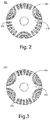
- FIG. 2 is a cross-sectional structural view of a 6-pole rotor of the embodiment of the present invention
- FIG. 3 is another cross-sectional structural view of the 6-pole rotor of the embodiment of the present invention.
- each of the flux barrier groups 120 and the slot groups 130 is set to be three groups.
- the flux barrier groups 120 may be set to be four groups, and the slot groups 130 may be set to be two groups.
- FIG. 4 is a cross-sectional structural view of an 8-pole rotor of the embodiment of the present invention
- FIG. 5 is another cross-sectional structural view of the 8-pole rotor of the embodiment of the present invention.
- each of the flux barrier groups 120 and the slot groups 130 is set to be four groups. That is, as shown in FIG. 5 , the flux barrier groups 120 may be set to be six groups, and the slot groups 130 may be set to be two groups.
- the quantity ratio of the flux barrier groups and the slot groups may be set based on the product requirements.
- the number of flux barrier groups and the number of slot groups may be set to be the same.
- the number of poles of the motor is four
- the flux barrier groups 120 is set to be two groups
- the slot groups 130 is set to be two groups.
- each of the flux barrier groups 120 and the slot groups 130 is set to be three groups.
- each of the flux barrier groups 120 and the slot groups 130 is set to be four groups.
- the flux barrier groups 120 and the slot groups 130 may be provided at intervals from each other, that is, they may be provided alternatively at intervals.
- the number of flux barrier groups may be set larger than the number of slot groups.
- the number of flux barrier groups is set to n times the number of slot groups.
- n is an integer greater than 1.
- the number of poles of the motor is six, and as shown in FIG. 3 , the number of flux barrier groups 120 is four, and the number of slot groups 130 is two.
- the number of poles of the motor is eight, and as shown in FIG. 5 , the number of flux barrier groups 120 is six, and the number of slot groups 130 is two.
- the spacing between the two slot groups 130 in the circumferential direction of the rotor iron core has at least two flux barrier groups 120.
- the number of slots groups may be set larger than the number of flux barrier groups.
- the spacing between at least two flux barrier groups in the circumferential direction of the rotor iron core has at least two slot groups.
- the at least two flux barrier groups 120 and the at least two slot groups 130 may be provided at equal intervals in the circumferential direction of the rotor iron core.
- the present invention is convenient for manufacturing the motor. Further, the stability of the motor performance can be guaranteed.
- the spacing between the at least two flux barrier groups 120 and the at least two slot groups 130 may not be set exactly the same.
- the number of flux barriers in each flux barrier group may be the same, and the number of slots in each slot group may be the same.
- the present invention is convenient for manufacturing the motor. Further, the stability of the motor performance can be guaranteed.
- the number of flux barriers in each flux barrier group may be different, or the number of flux barriers in some groups may be different, and/or the number of slots in each slot group may be different or the number of slots in some groups may be different.
- the number of flux barriers in a flux barrier group and the number of slots in a slot group can also be set based on the product requirements.
- the number of slots in a slot group can be made larger than the number of flux barriers in a flux barrier group, and thus the starting ability of the motor can be improved.
- the number of slots 131 in each slot group 130 is nine, and the number of flux barriers 121 in each flux barrier group 120 is three.
- the number of slots 131 in each slot group 130 is five, and the number of flux barriers 121 in each flux barrier group 120 is three.
- the number of slots 131 in each slot group 130 is six, and the number of flux barriers 121 in each flux barrier group 120 is three.
- each flux barrier in a flux barrier group and the shape and size of each slot in a slot group may be set based on actual requirements.
- each flux barrier 121 may be designed in an arc shape, and curved outward in the radial direction of the rotor iron core.
- the length of the arc on the radially outer side facing the rotor iron core of each flux barrier 121 gradually decreases, and the arc-shaped flux barriers 121 may be provided substantially parallel to each other.
- each arc-shaped flux barrier 121 may be the same, and the width of each arc-shaped flux barrier 121 may gradually decrease from the radially outer side to the radially inner side of the rotor iron core 110.
- the flux barrier 121 of the present embodiment does not have to be designed in an arc shape.
- it may be designed in a structure composed of a polygonal line similar to the locus of the arc shape, or it may be designed in a structure composed of an arc shape and a polygonal line.
- each slot 131 may be designed in a rod shape in which one end of the rotor iron core 100 facing radially inward is narrower with respect to one end facing radially outward. In this way, the passage path of the magnetic induction wire can be effectively guided.
- respective flux barriers in the same flux barrier group may be designed to have the same shape and/or size, or may be designed to be partially the same or different based on the requirements. Also, respective flux barriers in different flux barrier groups may be designed to be partially the same or different based on the requirements.
- respective slots in the same slot group may be designed to have the same shape and/or size, or may be designed to be partially the same or different based on the requirements.
- respective slots in different slot groups may be designed to be partially the same or different based on the requirements.
- each flux barrier and/or slot may be filled with a conductive non-magnetic material, for example, aluminum or copper. In this way, the motor can self-start.
- each flux barrier 121 and each slot 131 is filled with a conductive non-magnetic material 140.
- each flux barrier 121 may not be filled with the conductive non-magnetic material 140, and instead, a magnet can be inserted into each flux barrier 121 to increase the motor efficiency in this way.
Landscapes
- Engineering & Computer Science (AREA)
- Power Engineering (AREA)
- Iron Core Of Rotating Electric Machines (AREA)
Abstract
Description
- The present invention relates to the electromechanical field, and in particular, to a rotor and a motor having the rotor.
- In the use of motors, motors that do not require a controller and are directly connected and started by electric power currently have a high market share. Most of the motor types are conventional induction motors, but the efficiency of induction motors is generally at the IE3 efficiency level. To raise it to the IE4 efficiency level, it is imperative to use high quality materials in order to reduce the motor loss and further increase the efficiency, but high material costs must be paid. Most of the motors that reach IE4 level or higher efficiency in the current market are permanent magnet synchronous motors or synchronous reluctance motors, but all of the motors of the above-mentioned types must adopt a closed loop drive controller.
- In recent years, new motors replacing the motors of the above-mentioned types are gradually appearing, and self-start synchronous reluctance motor (Line start SynRM) is one of them. Such motors have self-starting ability of induction motors, and the efficiency of steady operation can reach the IE4 efficiency levels, similar to synchronous reluctance motors. Currently, self-starting synchronous reluctance motors are mainly divided into two types, that is, one in which a flux barrier is provided to the rotor of an existing induction motor, and one in which aluminum casting is directly made in a flux barrier of the rotor of a synchronous reluctance motor, and the rotor is also equipped with a cage conductor.
- The introduction of the above technical background is only for the purpose of making it easy to explain the technical measures of the present invention clearly and completely. It should be noted that it is described so as to allow those skilled in the art to understand easily. Since these measures are described only in the background technical part of the present invention, it cannot be said that the above technical measures are known to those skilled in the art. The present invention relates to a control device that controls an articulated robot.
- However, for a motor in which a flux barrier is provided to the rotor of an existing induction motor, since it is a structural modification of an existing induction motor, the torque component generated by the structure of the reluctance motor is small and the motor efficiency cannot be increased too much. Therefore, the rotation speed may not reach the synchronous speed at the rated efficiency. For a motor that is aluminum-casted directly in the flux barrier of the rotor of a synchronous reluctance motor, when the steady operation is at the synchronous rotation speed, the magnetic field mainly passes through a path other than the flux barrier in the rotor. Therefore, the magnetic field caused by the rotor conductor is reduced, and the loss caused by the rotor conductor is greatly reduced as compared with the conventional self-starting synchronous reluctance motor, whereby the efficiency of the entire motor is reduced.
- In order to solve the above problems, the present invention provides a rotor and a motor having the rotor. By providing a plurality of flux barrier groups and slot groups at intervals in a circumferential direction of the rotor iron core, it is possible to flexibly arrange the number of flux barrier groups and the number of slot groups so as to meet the requirements for the number of poles of different products. In addition, by flexibly adjusting the quantity ratio between the flux barrier groups and the slot groups and/or the quantity relationship between the flux barriers in the flux barrier group and the slots in the slot group, it is possible to meet the requirements for motor efficiency and starting capacity of different products. Further, since the processing jig of the rotor only requires processing of the structures of the flux barriers and the slots, the manufacturing cost can be reduced.
- According to a first aspect of an embodiment of the present invention, a rotor is provided. The rotor includes a rotor iron core including electrical steel sheets that are layered in an axial direction and rotate around a center axis. The rotor iron core includes at least two flux barrier groups and at least two slot groups penetrating the electrical steel sheets in the axial direction, the flux barrier group includes at least two flux barriers, and the slot group includes at least two slots. The at least two flux barrier groups and the at least two slot groups are provided at intervals in a circumferential direction of the rotor iron core.
- According to a second aspect of the embodiment of the present invention, a number of the flux barrier groups is same as a number of the slot groups, or the number of the flux barrier groups is larger than the number of the slot groups.
- According to a third aspect of the embodiment of the present invention, the number of the flux barrier groups is n times the number of the slot groups, and n is an integer greater than 1.
- According to a fourth aspect of the embodiment of the present invention, the number of the flux barrier groups is two, and the number of the slot groups is two, the number of the flux barrier groups is four, and the number of the slot groups is two, the number of the flux barrier groups is three, and the number of the slot groups is three, the number of the flux barrier groups is six, and the number of the slot groups is two, or the number of the flux barrier groups is four, and the number of the slot groups is four.
- According to a fifth aspect of the embodiment of the present invention, when the number of the flux barrier groups and the number of the slot groups are the same, the flux barrier groups and the slot groups are provided at intervals from each other.
- According to a sixth aspect of the embodiment of the present invention, when the number of the flux barrier groups is larger than the number of the slot groups, an interval between the at least two slot groups in the circumferential direction of the rotor iron core has at least two flux barrier groups.
- According to a seventh aspect of the embodiment of the present invention, the at least two flux barrier groups and the at least two slot groups are provided at equal intervals in the circumferential direction of the rotor iron core.
- According to an eighth aspect of the embodiment of the present invention, a number of slots in each of the slot groups is larger than the number of flux barriers in each of the flux barrier groups.
- According to a ninth aspect of the embodiment of the present invention, each of the flux barrier groups has at least two arc-shaped flux barriers, and each of the arc-shaped flux barriers is curved outward in a radial direction of the rotor iron core.
- According to a tenth aspect of the embodiment of the present invention, a width of each of the arc-shaped flux barriers is same, or the width of each of the arc-shaped flux barriers gradually decreases from a radially outer side to a radially inner side of the rotor iron core.
- According to an eleventh aspect of the embodiment of the present invention, one or both of each of the flux barriers and each of the slots is filled with a conductive non-magnetic material.
- According to a twelfth aspect of the embodiment of the present invention, a magnet is inserted in each of the flux barriers.
- According to a thirteenth aspect of the embodiment of the present invention, a motor having the rotor according to any one of the first aspect to the twelfth aspect of the embodiment of the present invention is provided.
- An advantageous effect of the embodiment of the present invention is that a plurality of flux barrier groups and a plurality of slot groups are provided at intervals in the circumferential direction of the rotor iron core so as to satisfy the requirements for the number of poles of different products, the number of flux barrier groups and the number of slot groups can be arranged flexibly. In addition, by flexibly adjusting the quantity ratio between the flux barrier groups and the slot groups and/or the quantity relationship between the flux barriers in the flux barrier group and the slots in the slot group, it is possible to meet the requirements for motor efficiency and starting capacity of different products. Further, since the processing jig of the rotor only requires processing of the structures of the flux barriers and the slots, the manufacturing cost can be reduced.
- An embodiment of the present invention is disclosed in detail with reference to the description and drawings of the following sentences. It should be understood that the scope of the embodiment of the present invention is not limited to this. Within the spirit of the appended claims and the covenant, the embodiment of the present invention includes many changes, modifications and equivalents.
- For one embodiment, the features described and/or shown may be used in one or more other embodiments in the same or similar manner, may be combined with features of other embodiments, or may be replaced with other implementation features.
- The term "provide/include/have", when used in the text, refers to the presence of a feature, the whole, or a member, and does not exclude the presence or addition of one or more other features, whole, or members.
-
-
FIG. 1 is a cross-sectional structural view of a motor of an embodiment of the present invention. -
FIG. 2 is a cross-sectional structural view of a 6-pole rotor of the embodiment of the present invention. -
FIG. 3 is another cross-sectional structural view of the 6-pole rotor of the embodiment of the present invention. -
FIG. 4 is a cross-sectional structural view of an 8-pole rotor of the embodiment of the present invention. -
FIG. 5 is another cross-sectional structural view of the 8-pole rotor of the embodiment of the present invention. - With reference to the drawings, the above and other features of the present invention will be clear. In the specification and the drawings, a specific embodiment of the present invention is specifically disclosed, and an embodiment in which the principles of the present invention can be adopted is shown. It should be understood that the present invention is not limited to the described embodiment, but includes all modifications and changes and equivalents that fall within the scope of the appended claims.
- In the present invention, a direction parallel to a direction in which the center axis extends is referred to as an "axial direction", a radial direction centered on the center axis is referred to as a "radial direction", and a circumferential direction around the center axis is referred to as a "circumferential direction". It should be noted that the definitions of the respective directions of the present invention are for the sake of facilitating the description of the embodiment of the present invention, and do not limit the directions in which the rotor and motor are used and manufactured.
- A rotor and a motor of an embodiment of the present invention will be described below.
- According to an embodiment of the present invention, a rotor and a motor having a rotor can be provided.
-
FIG. 1 is a cross-sectional structural view of a motor of the embodiment of the present invention. As shown inFIG. 1 , amotor 10 includes arotor 100. Themotor 10 further includes astator 200 and arotary shaft 300. Thestator 200, therotor 100, and therotary shaft 300 are provided in this order from the outside to the inside in the radial direction. - In this embodiment, the
stator 200 may have a conventional structure. For example, as shown inFIG. 1 , a plurality of coggingstructures 210 are provided in the circumferential direction of thestator 200. - Hereinafter, the structure of the
rotor 100 will be specifically described. - As shown in
FIG. 1 , therotor 100 has arotor iron core 110. Therotor iron core 110 is configured of electromagnetic steel plates that are layered in the axial direction and rotate about the center axis. - The
rotor iron core 110 has at least twoflux barrier groups 120 and at least twoslot groups 130 penetrating the electromagnetic steel plates in the axial direction. Theflux barrier group 120 has at least twoflux barriers 121, and theslot group 130 has at least twoslots 131. At least twoflux barrier groups 120 and at least twoslot groups 130 are spaced apart in the circumferential direction of therotor iron core 110. - As shown in
FIG. 1 , oneflux barrier group 120 and oneslot group 130 have flux barriers and slots in regions separated by dashed lines, respectively. - In the present embodiment, the
flux barrier group 120 includes at least twoflux barriers 121, and theslot group 130 includes at least twoslots 131. - The
rotor 100 may further have a rotary shaft hole located at the center of therotor iron core 110 so that therotary shaft 300 can pass through. - In the present embodiment, each of the number of flux barrier groups and the number of slot groups is at least two. The specific number of each group may be set based on actual requirements. The sum of the number of flux barrier groups and the number of slot groups may be the same as the number of poles of the motor.
- For example, description will be given on the case where the number of poles of the motor is six.
FIG. 2 is a cross-sectional structural view of a 6-pole rotor of the embodiment of the present invention, andFIG. 3 is another cross-sectional structural view of the 6-pole rotor of the embodiment of the present invention. As shown inFIG. 2 , each of theflux barrier groups 120 and theslot groups 130 is set to be three groups. As shown inFIG. 3 , theflux barrier groups 120 may be set to be four groups, and theslot groups 130 may be set to be two groups. - For example, description will be given on the case where the number of poles of the motor is eight.
FIG. 4 is a cross-sectional structural view of an 8-pole rotor of the embodiment of the present invention, andFIG. 5 is another cross-sectional structural view of the 8-pole rotor of the embodiment of the present invention. As shown inFIG. 4 , each of theflux barrier groups 120 and theslot groups 130 is set to be four groups. That is, as shown inFIG. 5 , theflux barrier groups 120 may be set to be six groups, and theslot groups 130 may be set to be two groups. - In the present embodiment, the quantity ratio of the flux barrier groups and the slot groups may be set based on the product requirements.
- In the present embodiment, when the requirements for motor efficiency and starting capacity basically match, the number of flux barrier groups and the number of slot groups may be set to be the same.
- For example, as shown in
FIG. 1 , the number of poles of the motor is four, theflux barrier groups 120 is set to be two groups, and theslot groups 130 is set to be two groups. - Further, for example, the number of poles of the motor is six, and as shown in
FIG. 2 , each of theflux barrier groups 120 and theslot groups 130 is set to be three groups. - Alternatively, for example, the number of poles of the motor is eight, and as shown in
FIG. 4 , each of theflux barrier groups 120 and theslot groups 130 is set to be four groups. - In that case, as shown in
FIGS. 1 ,2 , and4 , theflux barrier groups 120 and theslot groups 130 may be provided at intervals from each other, that is, they may be provided alternatively at intervals. - In the present embodiment, when the demand for motor efficiency is high, the number of flux barrier groups may be set larger than the number of slot groups.
- For example, the number of flux barrier groups is set to n times the number of slot groups. Here, n is an integer greater than 1. For example, the number of poles of the motor is six, and as shown in
FIG. 3 , the number offlux barrier groups 120 is four, and the number ofslot groups 130 is two. Alternatively, for example, the number of poles of the motor is eight, and as shown inFIG. 5 , the number offlux barrier groups 120 is six, and the number ofslot groups 130 is two. - In that case, as shown in
FIGS. 3 and5 , the spacing between the twoslot groups 130 in the circumferential direction of the rotor iron core has at least twoflux barrier groups 120. - Further, when the demand for starting ability of the motor is high, the number of slots groups may be set larger than the number of flux barrier groups. In that case, the spacing between at least two flux barrier groups in the circumferential direction of the rotor iron core has at least two slot groups.
- In the present embodiment, the at least two
flux barrier groups 120 and the at least twoslot groups 130 may be provided at equal intervals in the circumferential direction of the rotor iron core. As described above, the present invention is convenient for manufacturing the motor. Further, the stability of the motor performance can be guaranteed. - However, for a motor with specific requirements, the spacing between the at least two
flux barrier groups 120 and the at least twoslot groups 130 may not be set exactly the same. - In the present embodiment, the number of flux barriers in each flux barrier group may be the same, and the number of slots in each slot group may be the same. As described above, the present invention is convenient for manufacturing the motor. Further, the stability of the motor performance can be guaranteed.
- However, for a motor with specific requirements, the number of flux barriers in each flux barrier group may be different, or the number of flux barriers in some groups may be different, and/or the number of slots in each slot group may be different or the number of slots in some groups may be different.
- In the present embodiment, the number of flux barriers in a flux barrier group and the number of slots in a slot group can also be set based on the product requirements.
- For example, the number of slots in a slot group can be made larger than the number of flux barriers in a flux barrier group, and thus the starting ability of the motor can be improved.
- For example, as shown in
FIG. 1 , the number ofslots 131 in eachslot group 130 is nine, and the number offlux barriers 121 in eachflux barrier group 120 is three. - For example, as shown in
FIGS. 2 and 3 , the number ofslots 131 in eachslot group 130 is five, and the number offlux barriers 121 in eachflux barrier group 120 is three. - For example, as shown in
FIGS. 4 and 5 , the number ofslots 131 in eachslot group 130 is six, and the number offlux barriers 121 in eachflux barrier group 120 is three. - In the present embodiment, the shape of each flux barrier in a flux barrier group and the shape and size of each slot in a slot group may be set based on actual requirements.
- For example, as shown in
FIGS. 1 to 5 , eachflux barrier 121 may be designed in an arc shape, and curved outward in the radial direction of the rotor iron core. With respect to oneflux barrier group 120, the length of the arc on the radially outer side facing the rotor iron core of eachflux barrier 121 gradually decreases, and the arc-shapedflux barriers 121 may be provided substantially parallel to each other. - In the present embodiment, the width of each arc-shaped
flux barrier 121 may be the same, and the width of each arc-shapedflux barrier 121 may gradually decrease from the radially outer side to the radially inner side of therotor iron core 110. - Further, the
flux barrier 121 of the present embodiment does not have to be designed in an arc shape. For example, it may be designed in a structure composed of a polygonal line similar to the locus of the arc shape, or it may be designed in a structure composed of an arc shape and a polygonal line. - In the present embodiment, as shown in
FIGS. 2 to 5 for example, eachslot 131 may be designed in a rod shape in which one end of therotor iron core 100 facing radially inward is narrower with respect to one end facing radially outward. In this way, the passage path of the magnetic induction wire can be effectively guided. - In the present embodiment, respective flux barriers in the same flux barrier group may be designed to have the same shape and/or size, or may be designed to be partially the same or different based on the requirements. Also, respective flux barriers in different flux barrier groups may be designed to be partially the same or different based on the requirements.
- Similarly, respective slots in the same slot group may be designed to have the same shape and/or size, or may be designed to be partially the same or different based on the requirements. Also, respective slots in different slot groups may be designed to be partially the same or different based on the requirements.
- In the present embodiment, each flux barrier and/or slot may be filled with a conductive non-magnetic material, for example, aluminum or copper. In this way, the motor can self-start.
- For example, as shown in
FIG. 1 , eachflux barrier 121 and eachslot 131 is filled with a conductivenon-magnetic material 140. - In the present embodiment, each
flux barrier 121 may not be filled with the conductivenon-magnetic material 140, and instead, a magnet can be inserted into eachflux barrier 121 to increase the motor efficiency in this way. - As can be seen from the present embodiment described above, by providing a plurality of flux barrier groups and slot groups at intervals in the circumferential direction of the rotor iron core, it is possible to flexibly arrange the number of flux barrier groups and the number of slot groups so as to satisfy the requirements for the number of poles of different products. Moreover, by flexibly adjusting at least one of the quantity ratio between the flux barrier groups and the slot groups, the quantity relationship between the flux barriers in the flux barrier group and the slots in the slot group, the arrangement positions of the flux barrier groups and the slot groups, and the size of the flux barrier in the flux barrier group and the size of the slot in the slot group, it is possible to meet the requirements for the motor efficiency and for the start-up capacity of different products. Further, since the processing jig of the rotor only requires processing of the structures of the flux barriers and the slots, the manufacturing cost can be reduced.
- The embodiment of the present invention has been described in detail with reference to the drawings, and the method in which the principle of the present invention is adopted has been described. However, embodiment of the present invention is not limited to the above embodiment. All changes, modifications, and equivalents within the scope of the gist of the present invention are included.
Claims (13)
- A rotor comprising a rotor iron core including electrical steel sheets that are layered in an axial direction and rotate around a center axis,
wherein the rotor iron core includes at least two flux barrier groups and at least two slot groups penetrating the electrical steel sheets in the axial direction, each of the flux barrier groups includes at least two flux barriers, and each of the slot groups includes at least two slots, and
the at least two flux barrier groups and the at least two slot groups are provided at intervals in a circumferential direction of the rotor iron core. - The rotor according to claim 1, wherein
a number of the flux barrier groups is same as a number of the slot groups, or
the number of the flux barrier groups is larger than the number of the slot groups. - The rotor according to claim 2, wherein the number of the flux barrier groups is n times the number of the slot groups, and n is an integer greater than 1.
- The rotor according to claim 2, wherein
the number of the flux barrier groups is two, and the number of the slot groups is two,
the number of the flux barrier groups is four, and the number of the slot groups is two,
the number of the flux barrier groups is three, and the number of the slot groups is three,
the number of the flux barrier groups is six, and the number of the slot groups is two, or
the number of the flux barrier groups is four, and the number of the slot groups is four. - The rotor according to claim 2, wherein when the number of the flux barrier groups and the number of the slot groups are the same, the flux barrier groups and the slot groups are provided at intervals from each other.
- The rotor according to claim 2, wherein when the number of the flux barrier groups is larger than the number of the slot groups, an interval between the at least two slot groups in the circumferential direction of the rotor iron core has at least two flux barrier groups.
- The rotor according to claim 1, wherein the at least two flux barrier groups and the at least two slot groups are provided at equal intervals in the circumferential direction of the rotor iron core.
- The rotor according to claim 1, wherein a number of slots in each of the slot groups is larger than a number of flux barriers in each of the flux barrier groups.
- The rotor according to claim 1, wherein each of the flux barrier groups includes at least two arc-shaped flux barriers, and each of the arc-shaped flux barriers is curved outward in a radial direction of the rotor iron core.
- The rotor according to claim 9, wherein a width of each of the arc-shaped flux barriers is same, or the width of each of the arc-shaped flux barriers gradually decreases from a radially outer side to a radially inner side of the rotor iron core.
- The rotor according to claim 1, wherein one or both of each of the flux barriers and each of the slots is filled with a conductive non-magnetic material.
- The rotor according to claim 1, wherein a magnet is inserted in each of the flux barriers.
- A motor comprising the rotor according to any one of claims 1 to 12.
Applications Claiming Priority (2)
| Application Number | Priority Date | Filing Date | Title |
|---|---|---|---|
| CN201811030075.9A CN110880818B (en) | 2018-09-05 | 2018-09-05 | Rotor and motor having the same |
| PCT/JP2019/034654 WO2020050280A1 (en) | 2018-09-05 | 2019-09-03 | Rotor and motor equipped with rotor |
Publications (2)
| Publication Number | Publication Date |
|---|---|
| EP3849067A1 true EP3849067A1 (en) | 2021-07-14 |
| EP3849067A4 EP3849067A4 (en) | 2022-05-25 |
Family
ID=69722390
Family Applications (1)
| Application Number | Title | Priority Date | Filing Date |
|---|---|---|---|
| EP19857569.8A Withdrawn EP3849067A4 (en) | 2018-09-05 | 2019-09-03 | Rotor and motor equipped with rotor |
Country Status (4)
| Country | Link |
|---|---|
| US (1) | US11881746B2 (en) |
| EP (1) | EP3849067A4 (en) |
| CN (1) | CN110880818B (en) |
| WO (1) | WO2020050280A1 (en) |
Families Citing this family (3)
| Publication number | Priority date | Publication date | Assignee | Title |
|---|---|---|---|---|
| CN113675968B (en) * | 2020-05-15 | 2023-10-31 | 日本电产株式会社 | Rotor, motor and electric product |
| CN112713741A (en) * | 2020-12-21 | 2021-04-27 | 中车永济电机有限公司 | Self-starting three-phase synchronous reluctance motor |
| JP7725250B2 (en) * | 2021-06-17 | 2025-08-19 | ニデック株式会社 | Synchronous reluctance motor |
Family Cites Families (14)
| Publication number | Priority date | Publication date | Assignee | Title |
|---|---|---|---|---|
| CA920197A (en) | 1969-05-19 | 1973-01-30 | Allis-Chalmers Manufacturing Company | Synchronous reluctance motor |
| JP4472092B2 (en) * | 2000-02-17 | 2010-06-02 | 三菱電機株式会社 | Induction synchronous reluctance motor |
| JP3743348B2 (en) * | 2001-11-12 | 2006-02-08 | 三菱電機株式会社 | Synchronous induction motor, method for manufacturing synchronous induction motor, compressor |
| JP3775298B2 (en) | 2001-12-19 | 2006-05-17 | 三菱電機株式会社 | Synchronous motor, blower, compressor, refrigeration / air-conditioning equipment |
| JP2003259615A (en) | 2002-03-04 | 2003-09-12 | Mitsubishi Electric Corp | Reluctance motor |
| JP3775328B2 (en) * | 2002-03-27 | 2006-05-17 | 三菱電機株式会社 | Synchronous induction motor rotor, compressor, synchronous induction motor rotor manufacturing method, synchronous induction motor rotor mold |
| JP2006121765A (en) * | 2004-10-19 | 2006-05-11 | Mitsubishi Electric Corp | Reluctance rotary electric machine |
| KR100900290B1 (en) * | 2007-03-09 | 2009-05-29 | 엘지전자 주식회사 | motor |
| US20130181567A9 (en) * | 2007-08-28 | 2013-07-18 | Brusa Elektronik Ag | Hybrid synchronous motors and current-energized synchronous motors suitable for vehicle drives |
| JP2009077458A (en) * | 2007-09-18 | 2009-04-09 | Mitsui High Tec Inc | Rotor laminated core for reluctance motor |
| JP5361942B2 (en) * | 2011-05-19 | 2013-12-04 | 三菱電機株式会社 | Embedded magnet rotor, electric motor, compressor, air conditioner, and electric vehicle |
| JP2013021840A (en) * | 2011-07-12 | 2013-01-31 | Honda Motor Co Ltd | Rotor of reluctance motor |
| US10411537B2 (en) * | 2016-08-22 | 2019-09-10 | American Axle & Manufacturing, Inc. | Rotor lamination and related rotor and electric motor incorporating same |
| GB201619856D0 (en) | 2016-11-24 | 2017-01-11 | Jaguar Land Rover Ltd | Electric machine apparatus |
-
2018
- 2018-09-05 CN CN201811030075.9A patent/CN110880818B/en active Active
-
2019
- 2019-09-03 WO PCT/JP2019/034654 patent/WO2020050280A1/en not_active Ceased
- 2019-09-03 US US17/270,842 patent/US11881746B2/en active Active
- 2019-09-03 EP EP19857569.8A patent/EP3849067A4/en not_active Withdrawn
Also Published As
| Publication number | Publication date |
|---|---|
| CN110880818B (en) | 2022-07-19 |
| US20210211001A1 (en) | 2021-07-08 |
| EP3849067A4 (en) | 2022-05-25 |
| US11881746B2 (en) | 2024-01-23 |
| CN110880818A (en) | 2020-03-13 |
| WO2020050280A1 (en) | 2020-03-12 |
Similar Documents
| Publication | Publication Date | Title |
|---|---|---|
| EP2795776B1 (en) | Rotor for a line start permanent magnet machine | |
| US10749390B2 (en) | Line-start synchronous reluctance motor with improved performance | |
| RU2664505C1 (en) | Rotary electric machine | |
| CN110663158B (en) | Dual magnetic phase material ring for AC motor | |
| JP2020508631A5 (en) | ||
| US11881746B2 (en) | Rotor and motor having rotor | |
| US12009714B2 (en) | Rotating electric machine stator and rotating electric machine | |
| EP3836354A1 (en) | Rotor, synchronous reluctance motor, and method for forming rotor | |
| EP3007323B1 (en) | Rotating electrical machine in which permanent magnet is used | |
| CN102957235A (en) | Switch reluctance machine | |
| CN119652046B (en) | A dual-squirrel-cage permanent magnet motor with fractional slot concentrated windings and a pole-changing switching method | |
| EP3300230A1 (en) | Permanent magnet motor | |
| WO2019008848A1 (en) | Rotating electric machine and direct-acting electric motor | |
| CN208674969U (en) | Motor stator and motor | |
| EP3011662B1 (en) | Rotor for a rotating electrical machine | |
| WO2016053352A1 (en) | Rotor for consequent pole permanent magnet machine | |
| JP2002272067A (en) | Basket-shaped rotor and electric motor using the cage-shaped rotor | |
| US11770035B2 (en) | Laminated core for an electric machine | |
| KR20130056980A (en) | Squirrel cage rotor of induction motor | |
| JP2009296745A (en) | Multipole axial gap-type capacitor motor and its manufacturing method | |
| CN106655573A (en) | Solid rotor for high-power and high-speed asynchronous motor | |
| CN206302229U (en) | Solid rotor for high power and high speed asynchronous motor | |
| KR20210066973A (en) | Rotor of hybrid squirrel cage induction motor, motor and rotor manufacturing method using same | |
| CN114520549B (en) | Self-starting synchronous reluctance motor | |
| JP5975759B2 (en) | Rotating electric machine |
Legal Events
| Date | Code | Title | Description |
|---|---|---|---|
| STAA | Information on the status of an ep patent application or granted ep patent |
Free format text: STATUS: THE INTERNATIONAL PUBLICATION HAS BEEN MADE |
|
| PUAI | Public reference made under article 153(3) epc to a published international application that has entered the european phase |
Free format text: ORIGINAL CODE: 0009012 |
|
| STAA | Information on the status of an ep patent application or granted ep patent |
Free format text: STATUS: REQUEST FOR EXAMINATION WAS MADE |
|
| 17P | Request for examination filed |
Effective date: 20210301 |
|
| AK | Designated contracting states |
Kind code of ref document: A1 Designated state(s): AL AT BE BG CH CY CZ DE DK EE ES FI FR GB GR HR HU IE IS IT LI LT LU LV MC MK MT NL NO PL PT RO RS SE SI SK SM TR |
|
| DAV | Request for validation of the european patent (deleted) | ||
| DAX | Request for extension of the european patent (deleted) | ||
| REG | Reference to a national code |
Ref country code: DE Ref legal event code: R079 Free format text: PREVIOUS MAIN CLASS: H02K0017260000 Ipc: H02K0001240000 |
|
| A4 | Supplementary search report drawn up and despatched |
Effective date: 20220426 |
|
| RIC1 | Information provided on ipc code assigned before grant |
Ipc: H02K 19/14 20060101ALI20220420BHEP Ipc: H02K 17/26 20060101ALI20220420BHEP Ipc: H02K 17/16 20060101ALI20220420BHEP Ipc: H02K 1/26 20060101ALI20220420BHEP Ipc: H02K 1/24 20060101AFI20220420BHEP |
|
| STAA | Information on the status of an ep patent application or granted ep patent |
Free format text: STATUS: THE APPLICATION HAS BEEN WITHDRAWN |
|
| 18W | Application withdrawn |
Effective date: 20230628 |