EP3848993A1 - Secondary battery - Google Patents
Secondary battery Download PDFInfo
- Publication number
- EP3848993A1 EP3848993A1 EP19868707.1A EP19868707A EP3848993A1 EP 3848993 A1 EP3848993 A1 EP 3848993A1 EP 19868707 A EP19868707 A EP 19868707A EP 3848993 A1 EP3848993 A1 EP 3848993A1
- Authority
- EP
- European Patent Office
- Prior art keywords
- electrode
- secondary battery
- length
- insulator
- connection part
- Prior art date
- Legal status (The legal status is an assumption and is not a legal conclusion. Google has not performed a legal analysis and makes no representation as to the accuracy of the status listed.)
- Pending
Links
- 239000012212 insulator Substances 0.000 claims abstract description 21
- 230000004308 accommodation Effects 0.000 claims abstract description 5
- 239000011248 coating agent Substances 0.000 claims description 13
- 238000000576 coating method Methods 0.000 claims description 13
- 229910000831 Steel Inorganic materials 0.000 claims description 7
- 239000010959 steel Substances 0.000 claims description 7
- 229910052782 aluminium Inorganic materials 0.000 claims description 6
- XAGFODPZIPBFFR-UHFFFAOYSA-N aluminium Chemical compound [Al] XAGFODPZIPBFFR-UHFFFAOYSA-N 0.000 claims description 6
- 229920000642 polymer Polymers 0.000 claims description 5
- 238000004519 manufacturing process Methods 0.000 description 10
- PXHVJJICTQNCMI-UHFFFAOYSA-N Nickel Chemical compound [Ni] PXHVJJICTQNCMI-UHFFFAOYSA-N 0.000 description 9
- 239000007772 electrode material Substances 0.000 description 8
- OKTJSMMVPCPJKN-UHFFFAOYSA-N Carbon Chemical compound [C] OKTJSMMVPCPJKN-UHFFFAOYSA-N 0.000 description 5
- 238000004458 analytical method Methods 0.000 description 5
- 230000008878 coupling Effects 0.000 description 5
- 238000010168 coupling process Methods 0.000 description 5
- 238000005859 coupling reaction Methods 0.000 description 5
- 239000000463 material Substances 0.000 description 5
- -1 polyethylene Polymers 0.000 description 5
- 230000000052 comparative effect Effects 0.000 description 4
- 239000011810 insulating material Substances 0.000 description 4
- 239000007773 negative electrode material Substances 0.000 description 4
- 239000004698 Polyethylene Substances 0.000 description 3
- 239000004743 Polypropylene Substances 0.000 description 3
- 230000008901 benefit Effects 0.000 description 3
- 229910052759 nickel Inorganic materials 0.000 description 3
- 229920000573 polyethylene Polymers 0.000 description 3
- 229920001155 polypropylene Polymers 0.000 description 3
- 239000007774 positive electrode material Substances 0.000 description 3
- VYPSYNLAJGMNEJ-UHFFFAOYSA-N Silicium dioxide Chemical compound O=[Si]=O VYPSYNLAJGMNEJ-UHFFFAOYSA-N 0.000 description 2
- 239000010949 copper Substances 0.000 description 2
- 239000011888 foil Substances 0.000 description 2
- 229910002804 graphite Inorganic materials 0.000 description 2
- 239000010439 graphite Substances 0.000 description 2
- 229920000139 polyethylene terephthalate Polymers 0.000 description 2
- 239000005020 polyethylene terephthalate Substances 0.000 description 2
- HBMJWWWQQXIZIP-UHFFFAOYSA-N silicon carbide Chemical compound [Si+]#[C-] HBMJWWWQQXIZIP-UHFFFAOYSA-N 0.000 description 2
- 229910010271 silicon carbide Inorganic materials 0.000 description 2
- RYGMFSIKBFXOCR-UHFFFAOYSA-N Copper Chemical compound [Cu] RYGMFSIKBFXOCR-UHFFFAOYSA-N 0.000 description 1
- 229910000733 Li alloy Inorganic materials 0.000 description 1
- WHXSMMKQMYFTQS-UHFFFAOYSA-N Lithium Chemical compound [Li] WHXSMMKQMYFTQS-UHFFFAOYSA-N 0.000 description 1
- 239000011149 active material Substances 0.000 description 1
- 239000000956 alloy Substances 0.000 description 1
- 229910045601 alloy Inorganic materials 0.000 description 1
- 229910021383 artificial graphite Inorganic materials 0.000 description 1
- 229910052799 carbon Inorganic materials 0.000 description 1
- 239000011247 coating layer Substances 0.000 description 1
- 150000001875 compounds Chemical class 0.000 description 1
- 229910052802 copper Inorganic materials 0.000 description 1
- 230000000694 effects Effects 0.000 description 1
- 238000005516 engineering process Methods 0.000 description 1
- 238000002474 experimental method Methods 0.000 description 1
- 230000017525 heat dissipation Effects 0.000 description 1
- 235000015110 jellies Nutrition 0.000 description 1
- 239000008274 jelly Substances 0.000 description 1
- 229910052744 lithium Inorganic materials 0.000 description 1
- 239000001989 lithium alloy Substances 0.000 description 1
- 229910000625 lithium cobalt oxide Inorganic materials 0.000 description 1
- GELKBWJHTRAYNV-UHFFFAOYSA-K lithium iron phosphate Chemical compound [Li+].[Fe+2].[O-]P([O-])([O-])=O GELKBWJHTRAYNV-UHFFFAOYSA-K 0.000 description 1
- 229910002102 lithium manganese oxide Inorganic materials 0.000 description 1
- BFZPBUKRYWOWDV-UHFFFAOYSA-N lithium;oxido(oxo)cobalt Chemical compound [Li+].[O-][Co]=O BFZPBUKRYWOWDV-UHFFFAOYSA-N 0.000 description 1
- VLXXBCXTUVRROQ-UHFFFAOYSA-N lithium;oxido-oxo-(oxomanganiooxy)manganese Chemical compound [Li+].[O-][Mn](=O)O[Mn]=O VLXXBCXTUVRROQ-UHFFFAOYSA-N 0.000 description 1
- URIIGZKXFBNRAU-UHFFFAOYSA-N lithium;oxonickel Chemical compound [Li].[Ni]=O URIIGZKXFBNRAU-UHFFFAOYSA-N 0.000 description 1
- 229910052751 metal Inorganic materials 0.000 description 1
- 239000002184 metal Substances 0.000 description 1
- 238000000034 method Methods 0.000 description 1
- 239000000203 mixture Substances 0.000 description 1
- 239000002006 petroleum coke Substances 0.000 description 1
- 239000002861 polymer material Substances 0.000 description 1
- 229920005672 polyolefin resin Polymers 0.000 description 1
- 238000010248 power generation Methods 0.000 description 1
- 238000000926 separation method Methods 0.000 description 1
- 150000003377 silicon compounds Chemical class 0.000 description 1
- 239000000377 silicon dioxide Substances 0.000 description 1
- 150000003606 tin compounds Chemical class 0.000 description 1
- 150000003609 titanium compounds Chemical class 0.000 description 1
Images


Classifications
-
- H—ELECTRICITY
- H01—ELECTRIC ELEMENTS
- H01M—PROCESSES OR MEANS, e.g. BATTERIES, FOR THE DIRECT CONVERSION OF CHEMICAL ENERGY INTO ELECTRICAL ENERGY
- H01M10/00—Secondary cells; Manufacture thereof
- H01M10/04—Construction or manufacture in general
- H01M10/0422—Cells or battery with cylindrical casing
-
- H—ELECTRICITY
- H01—ELECTRIC ELEMENTS
- H01M—PROCESSES OR MEANS, e.g. BATTERIES, FOR THE DIRECT CONVERSION OF CHEMICAL ENERGY INTO ELECTRICAL ENERGY
- H01M50/00—Constructional details or processes of manufacture of the non-active parts of electrochemical cells other than fuel cells, e.g. hybrid cells
- H01M50/10—Primary casings; Jackets or wrappings
- H01M50/102—Primary casings; Jackets or wrappings characterised by their shape or physical structure
- H01M50/107—Primary casings; Jackets or wrappings characterised by their shape or physical structure having curved cross-section, e.g. round or elliptic
-
- H—ELECTRICITY
- H01—ELECTRIC ELEMENTS
- H01M—PROCESSES OR MEANS, e.g. BATTERIES, FOR THE DIRECT CONVERSION OF CHEMICAL ENERGY INTO ELECTRICAL ENERGY
- H01M10/00—Secondary cells; Manufacture thereof
- H01M10/04—Construction or manufacture in general
- H01M10/0431—Cells with wound or folded electrodes
-
- H—ELECTRICITY
- H01—ELECTRIC ELEMENTS
- H01M—PROCESSES OR MEANS, e.g. BATTERIES, FOR THE DIRECT CONVERSION OF CHEMICAL ENERGY INTO ELECTRICAL ENERGY
- H01M10/00—Secondary cells; Manufacture thereof
- H01M10/05—Accumulators with non-aqueous electrolyte
- H01M10/058—Construction or manufacture
- H01M10/0587—Construction or manufacture of accumulators having only wound construction elements, i.e. wound positive electrodes, wound negative electrodes and wound separators
-
- H—ELECTRICITY
- H01—ELECTRIC ELEMENTS
- H01M—PROCESSES OR MEANS, e.g. BATTERIES, FOR THE DIRECT CONVERSION OF CHEMICAL ENERGY INTO ELECTRICAL ENERGY
- H01M50/00—Constructional details or processes of manufacture of the non-active parts of electrochemical cells other than fuel cells, e.g. hybrid cells
- H01M50/10—Primary casings; Jackets or wrappings
- H01M50/116—Primary casings; Jackets or wrappings characterised by the material
- H01M50/117—Inorganic material
- H01M50/119—Metals
-
- H—ELECTRICITY
- H01—ELECTRIC ELEMENTS
- H01M—PROCESSES OR MEANS, e.g. BATTERIES, FOR THE DIRECT CONVERSION OF CHEMICAL ENERGY INTO ELECTRICAL ENERGY
- H01M50/00—Constructional details or processes of manufacture of the non-active parts of electrochemical cells other than fuel cells, e.g. hybrid cells
- H01M50/10—Primary casings; Jackets or wrappings
- H01M50/147—Lids or covers
- H01M50/148—Lids or covers characterised by their shape
- H01M50/152—Lids or covers characterised by their shape for cells having curved cross-section, e.g. round or elliptic
-
- H—ELECTRICITY
- H01—ELECTRIC ELEMENTS
- H01M—PROCESSES OR MEANS, e.g. BATTERIES, FOR THE DIRECT CONVERSION OF CHEMICAL ENERGY INTO ELECTRICAL ENERGY
- H01M50/00—Constructional details or processes of manufacture of the non-active parts of electrochemical cells other than fuel cells, e.g. hybrid cells
- H01M50/10—Primary casings; Jackets or wrappings
- H01M50/183—Sealing members
- H01M50/19—Sealing members characterised by the material
- H01M50/193—Organic material
-
- H—ELECTRICITY
- H01—ELECTRIC ELEMENTS
- H01M—PROCESSES OR MEANS, e.g. BATTERIES, FOR THE DIRECT CONVERSION OF CHEMICAL ENERGY INTO ELECTRICAL ENERGY
- H01M50/00—Constructional details or processes of manufacture of the non-active parts of electrochemical cells other than fuel cells, e.g. hybrid cells
- H01M50/50—Current conducting connections for cells or batteries
- H01M50/543—Terminals
- H01M50/545—Terminals formed by the casing of the cells
-
- H—ELECTRICITY
- H01—ELECTRIC ELEMENTS
- H01M—PROCESSES OR MEANS, e.g. BATTERIES, FOR THE DIRECT CONVERSION OF CHEMICAL ENERGY INTO ELECTRICAL ENERGY
- H01M50/00—Constructional details or processes of manufacture of the non-active parts of electrochemical cells other than fuel cells, e.g. hybrid cells
- H01M50/50—Current conducting connections for cells or batteries
- H01M50/543—Terminals
- H01M50/547—Terminals characterised by the disposition of the terminals on the cells
- H01M50/548—Terminals characterised by the disposition of the terminals on the cells on opposite sides of the cell
-
- Y—GENERAL TAGGING OF NEW TECHNOLOGICAL DEVELOPMENTS; GENERAL TAGGING OF CROSS-SECTIONAL TECHNOLOGIES SPANNING OVER SEVERAL SECTIONS OF THE IPC; TECHNICAL SUBJECTS COVERED BY FORMER USPC CROSS-REFERENCE ART COLLECTIONS [XRACs] AND DIGESTS
- Y02—TECHNOLOGIES OR APPLICATIONS FOR MITIGATION OR ADAPTATION AGAINST CLIMATE CHANGE
- Y02E—REDUCTION OF GREENHOUSE GAS [GHG] EMISSIONS, RELATED TO ENERGY GENERATION, TRANSMISSION OR DISTRIBUTION
- Y02E60/00—Enabling technologies; Technologies with a potential or indirect contribution to GHG emissions mitigation
- Y02E60/10—Energy storage using batteries
-
- Y—GENERAL TAGGING OF NEW TECHNOLOGICAL DEVELOPMENTS; GENERAL TAGGING OF CROSS-SECTIONAL TECHNOLOGIES SPANNING OVER SEVERAL SECTIONS OF THE IPC; TECHNICAL SUBJECTS COVERED BY FORMER USPC CROSS-REFERENCE ART COLLECTIONS [XRACs] AND DIGESTS
- Y02—TECHNOLOGIES OR APPLICATIONS FOR MITIGATION OR ADAPTATION AGAINST CLIMATE CHANGE
- Y02P—CLIMATE CHANGE MITIGATION TECHNOLOGIES IN THE PRODUCTION OR PROCESSING OF GOODS
- Y02P70/00—Climate change mitigation technologies in the production process for final industrial or consumer products
- Y02P70/50—Manufacturing or production processes characterised by the final manufactured product
Definitions
- the present invention relate to a secondary battery.
- Secondary batteries are rechargeable unlike primarily batteries, and also, the possibility of compact size and high capacity is high. Thus, recently, many studies on secondary batteries are being carried out. As technology development and demands for mobile devices increase, the demands for secondary batteries as energy sources are rapidly increasing.
- Secondary batteries are classified into coin type cells, cylindrical type cells, prismatic type cells, and pouch type cells according to a shape of a battery case.
- an electrode assembly mounted in a battery case is a chargeable and dischargeable power generating device having a structure in which an electrode and a separator are stacked.
- the electrode assembly may be approximately classified into a jelly-roll type electrode assembly in which a separator is interposed between a positive electrode and a negative electrode, each of which is provided as the form of a sheet coated with an active material, and then, the positive electrode, the separator, and the negative electrode are wound, a stacked type electrode assembly in which a plurality of positive and negative electrodes with a separator therebetween are sequentially stacked, and a stack/folding type electrode assembly in which stacked type unit cells are wound together with a separation film having a long length.
- the jelly-roll type electrode assembly is widely used because the jelly-roll type electrode assembly has an advantage that it is easily manufactured and has high energy density per weight.
- One aspect of the prevent invention is to provide a secondary battery that is capable of reducing the number of manufacturing processes and securing reliability such as sealability.
- Another aspect of the prevent invention is to provide a secondary battery that is disconnected between a can and an electrode assembly when an internal pressure of the battery reaches a critical point or more.
- a secondary battery comprises an electrode assembly in which a first electrode, a separator, and a second electrode are alternately stacked to be wound, a can provided with an accommodation part that accommodates the electrode assembly therein, the can comprising a first can and a second can, which have cylindrical shapes opened in a direction facing each other, and an insulator configured to insulate an overlapping portion between the first can and the second can, wherein the first can forms a first electrode terminal that directly contacts an end of the first electrode, and the second can forms a second electrode terminal that directly contacts an end of the second electrode.
- the two cans since the two cans are assembled in the press-fitting manner to allow each of the positive electrode and the negative electrode to be connected, the two cans may serve as the positive electrode terminal and the negative electrode terminal to simplify the manufacturing process, secure the reliability such as the sealability, and easily manufacture the large-capacity medium and large battery. Therefore, the high productivity and the low manufacturing costs may be realized.
- the coupling of the two cans that are press-fitted into and coupled to each other may be released, and the electrode assembly coupled to the two cans may be disconnected. Therefore, when the internal temperature and pressure of the battery suddenly increase due to the overcharging and the external short-circuit of the secondary battery, the coupling of the two cans that are press-fitted into and coupled to each other may be released to perform the safety function such as the current interruption function without the additional safety device.
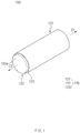
- FIG. 1 is a perspective view of a secondary battery according to an embodiment of the present invention
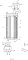
- FIG. 2 is an exploded perspective view of the secondary battery according to an embodiment of the present invention.
- a secondary battery 100 comprises an electrode assembly 110, a can 120 comprising a first can 121 and a second can 122, which accommodate the electrode assembly 110 therein, and an insulator 123 insulating an overlapping portion between the first can 121 and the second can 122.
- FIG. 3 is a cross-sectional view of the secondary battery according to an embodiment of the present invention.
- the electrode assembly 110 may be a chargeable and dischargeable power generation element and have a structure in which an electrode 113 and the separator 114 are combined to be alternately stacked with each other.
- the electrode assembly 110 may have a wound shape.
- the electrode 113 may comprise the first electrode 111 and the second electrode 112. Also, the separator 114 may separate the first electrode 111 from the second electrode 112 to insulate the first and second electrodes 111 and 112 from each other.
- each of the first electrode 111 and the second electrode may be provided in the form of a sheet and then be wound together with the separator 114 so as to be formed in a jelly roll type.
- the electrode assembly 110 may be wound, for example, in a cylindrical shape.
- the first electrode 111 may comprise a first electrode collector 111a and a first electrode active material 111b applied on the first electrode collector 111a. Also, the first electrode 111 may comprises a first electrode non-coating portion 111c that is not coated with the first electrode active material 111b.
- the first electrode 111 may be provided as, for example, a positive electrode and comprise a positive electrode collector (not shown) and a positive electrode active material (not shown) applied on the positive electrode collector. Also, a positive electrode non-coating portion that is not coated with the positive electrode active material may be formed on the first electrode 111.
- the positive electrode collector may be provided as foil made of an aluminum material, and the positive electrode active material may be made of lithium manganese oxide, lithium cobalt oxide, lithium nickel oxide, lithium iron phosphate, or a compound or mixture thereof containing at least one or more of the above-described materials.
- the second electrode 112 may comprise a second electrode collector 112a and a second electrode active material 112b applied on the second electrode collector 112a. Also, the second electrode 112 may comprises a second electrode non-coating portion 112c that is not coated with the second electrode active material 112b.
- the second electrode 112 may be provided as, for example, a negative electrode and comprise a negative electrode collector (not shown) and a negative electrode active material (not shown) applied on the negative electrode collector. Also, a negative electrode non-coating portion that is not coated with the negative electrode active material may be formed on the second electrode 112.
- the negative electrode collector may be provided as foil made of a copper (Cu) or nickel (Ni) material.
- the negative electrode active material may comprise synthetic graphite, lithium a metal, a lithium alloy, carbon, petroleum coke, activated carbon, graphite, a silicon compound, a tin compound, a titanium compound, or an alloy thereof.
- the negative electrode active material may further comprise, for example, non-graphite-based SiO (silica) or SiC (silicon carbide).
- the separator 114 may be made of an insulating material, and the first electrode 111, the separator 114, and the second electrode 112 may be alternately stacked.
- the separator 114 may be disposed between the first electrode 111 and the second electrode on outer surfaces of the first electrode 111 and the second electrode 112.
- the separator 114 may be disposed at the outermost side in a width direction when the electrode assembly 110 is wound.
- the separator 114 may be made of a flexible material.
- the separator 114 may be made of, for example, a polyolefin-based resin film such as polyethylene or polypropylene having micropores.
- the can 120 may be provided with an accommodation part that accommodates the electrode assembly 110 therein and comprise a first can 121 and a second can 122, which have cylindrical shapes opened in a direction facing each other.
- the first can 121 may be electrically connected to the first electrode 111, and the second can 122 may be electrically connected to the second electrode 112.
- the first can 121 may directly contact an end of the first electrode 111 to form a first electrode terminal, and the second can 122 may directly contact an end of the second electrode 112 to form a second electrode terminal.
- first can 121 and the second can 122 may be formed in shape corresponding to each other.
- each of the first can 121 and the second can 122 may have the cylindrical shape.
- the first can 121 may have an inner circumferential surface greater than an outer circumferential surface of the second can 122 so that the second can is inserted into the first can 121.
- the first can 121 may have one side 121b on which a first connection part 121a closed in one direction C1 may be formed and the other side 121c in which a first opening 121d opened in the other direction C2 is formed.
- the second can 122 may have the other side 122c on which a second connection part 122a closed in the other direction C2 is formed and one side 122b in which a second opening (not shown) opened in the one direction C1 is formed.
- the first electrode 111 may have one end connected to the first connection part 121a
- the second electrode 112 may have the other end connected to the second connection part 122a.
- the first electrode non-coating portion 111c of the first electrode 111 may directly contact the first connection part 121a
- the second electrode non-coating portion 112c of the second electrode 112 may directly contact the second connection portion 122a.
- the first can 121 disposed at the outside may comprise aluminum (Al), and the second can 122 disposed at the inside may comprise steel.
- the second can 122 may be made of steel coated with nickel (Ni).
- the first electrode 111 may be provided as a positive electrode
- the second electrode 112 may be provided as a negative electrode.
- a length L1 of the electrode assembly 110 in a longitudinal direction L may be greater than a length L2 of the second can 122 in the longitudinal direction L.
- an end of the second can 122 may not contact the first connection part 121a.
- the insulator 123 surrounds an end of the second can 122 so as to easily prevent short circuit from occurring and prevent the end of the second can 122 from contacting the first connection part 121a.
- a length V of an overlapping section between the first can 121 and the second can 122 is longer than a diameter r1 of the first can 121 and a diameter r2 of the second can 122. Thus, reliability such as sealability may be secured.
- the length of the first can 121 may be 70% or more of the length of the second can 122.
- the length of the overlapping section between the first can 121 and the second can 122 may be 70% or more and less than 100% of the total length of the can 120.
- each of the lengths of the first can 121 and the second can 122 in the longitudinal direction L may be in a range of 100 mm to 250 mm.
- a length L3 of the can 120 to which the first can 121 and the second can 122 are coupled may also be in a range of 100 mm to 250 mm.
- each of the diameters r1 and r2 of the first can 121 and the second can 122 may be in a range of 40 mm to 60 mm.
- the insulator 123 may comprise an insulating material to insulate the overlapping portion between the first can 121 and the second can 122.
- the insulator 123 may comprise an insulating polymer.
- the insulating polymer may be, for example, a polymer.
- the polymer may comprise, for example, any one of polyethylene (PE), polypropylene (PP), and polyethylene terephthalate (PET).
- the insulator 123 may be provided on an outer circumferential surface of the second can 122 in the form of one of tubing, wrapping, or coating.
- the tubing form may be a form in which the insulator 123 is provided on the outer circumferential surface of the second can 122 in the form of a tube
- the wrapping form may be a form in which the outer circumferential surface of the second can 122 is wrapped by the insulator 123
- the coating form may be a form in which a coating layer is formed by applying an insulating material on the outer circumferential surface of the second can 122.
- first can 121 and the second can 122 may be coupled to each other in a press-fitting manner. That is, the second can 122 provided with the insulator 123 on the outer circumferential surface thereof may be press-fitted into and coupled to an inner circumferential surface of the first can 121.
- the first can 121 and the second can 122 may be assembled in the press-fitting manner to allow the first electrode 111 and the second electrode 112 to be connected to each other.
- the first can 121 and the second can 122 may serve as a first electrode terminal and a second electrode terminal to simplify the assembly, secure the reliability such as the sealability, and easily manufacture a large-capacity medium and large battery. Therefore, high productivity and low manufacturing costs may be realized.
- the coupling of the first can 121 and the second can 122, which are coupled to each other in the press-fitting manner, may be released, and the electrode assembly 110 coupled to the first can 121 and the second can 122 may be disconnected. That is, when the internal pressure of the battery reaches the critical point or more, the first can 121 and the second can 122 may be subjected to pressures by which the first can 121 and the second can 122 are spaced apart from each other. As a result, the first can 121 may move in one direction C1, and the second can 122 may move in the other direction C2 to release the press-fitted coupling between the first can 121 and the second can 122.
- ends of the first electrode 111 and the second electrode 112, which directly contact the first can 121 and the second can 122, and the first can 121 or the second can 122 may be disconnected to interrupt the current. Therefore, when the internal temperature and pressure of the battery suddenly increase due to the overcharging and the external short-circuit of the secondary battery 100, the coupling of the first can 121 and the second can 122, which are press-fitted into and coupled to each other, may be released to perform a safety function such as the current interruption function without an additional safety device.
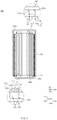
- FIG. 4 is an exploded perspective view of a secondary battery according to another embodiment of the present invention
- FIG. 5 is a cross-sectional view of the secondary battery according to another embodiment of the present invention.
- a secondary battery 200 according to another embodiment of the present invention comprises an electrode assembly 210, a can 120 comprising a first can 221 and a second can 222, which accommodate the electrode assembly 210 therein, and an insulator 223 insulating an overlapping portion between the first can 221 and the second can 222.
- the secondary battery 200 according to another embodiment of the present invention is different from the secondary battery according to the foregoing embodiment in materials of the first can 221 and the second can 222 and polarities of the first electrode 211 and the second electrode 212.
- contents of this embodiment which are duplicated with those according to the forgoing embodiment, will be briefly described, and also, differences therebetween will be mainly described.
- the electrode assembly 210 forms a structure in which the electrodes 213 and a separator 214 are alternately stacked.
- the electrode assembly 210 may have a wound shape.
- the electrode 213 may comprise the first electrode 211 and the second electrode 212.
- the first electrode 211 may comprise a first electrode collector 211a and a first electrode active material 211b applied on the first electrode collector 211a. Also, the first electrode 211 may comprises a first electrode non-coating portion 211c that is not coated with the first electrode active material 211b.
- the second electrode 212 may comprise a second electrode collector 212a and a second electrode active material 212b applied on the second electrode collector 212a. Also, the second electrode 212 may comprises a second electrode non-coating portion 212c that is not coated with the second electrode active material 212b.
- the can 220 may be provided with an accommodation part that accommodates the electrode assembly 210 therein and comprise the first can 221 and the second can 222, which have cylindrical shapes opened in a direction facing each other.
- first can 221 may be electrically connected to the first electrode 211
- second can 222 may be electrically connected to the second electrode 212.
- each of the first can 221 and the second can 222 may have the cylindrical shape.
- the first can 221 may have an inner circumferential surface greater than an outer circumferential surface of the second can 222 so that the second can is inserted into the first can 221.
- the first can 221 may have one side 221b on which a first connection part 221a closed in one direction C1 may be formed and the other side 221c in which a first opening 221d opened in the other direction C2 is formed.
- the second can 222 may have the other side 222c on which a second connection part 222a closed in the other direction C2 is formed and one side 222b in which a second opening (not shown) opened in the one direction C1 is formed.
- the first electrode 211 may have one end connected to the first connection part 221a
- the second electrode 212 may have the other end connected to the second connection part 222a.
- the first electrode non-coating portion 211c of the first electrode 211 may directly contact the first connection part 221a
- the second electrode non-coating portion 212c of the second electrode 212 may directly contact the second connection portion 222a.
- the first can 221 disposed at the outside may comprise steel, and the second can 222 disposed at the inside may comprise aluminum.
- the first can 221 may be made of steel coated with nickel (Ni).
- the first electrode 211 may be provided as the negative electrode
- the second electrode 212 may be provided as the positive electrode
- the insulator 223 may comprise an insulating material to insulate the overlapping portion between the first can 221 and the second can 222.
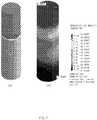
- FIG. 6 is a view illustrating a temperature analysis of the can in the secondary battery according to an embodiment of the present invention.
- a can comprising a first can and a second can, which have cylindrical shapes opened in a direction facing each other, was manufactured.
- the first can disposed at the outside was made of aluminum
- the second can disposed at the inside was made of steel.
- the second can has a thickness of 0.2 t.
- an insulator for insulating an overlapping portion between the first can and the second can was provided.
- the outer can which is the first can
- the inner can which is the second can
- the insulator was formed to have a length of 195 mm.
- a blue color represents the inner can (second can)
- a purple color represents the outer can (first can)
- a gray color represents the insulator.
- FIG. 7 is a view illustrating a temperature analysis of a can in a secondary battery according to a related art that is Comparative Example.
- the secondary battery was manufactured in the same method as that of Manufacturing Example except for an outer can has a length of 120 mm, an inner can has a length of 120 mm, and an insulator has a length of 50 mm.
- a blue color represents the inner can
- a purple color represents the outer can
- a gray color represents the insulator.
Landscapes
- Chemical & Material Sciences (AREA)
- Chemical Kinetics & Catalysis (AREA)
- Electrochemistry (AREA)
- General Chemical & Material Sciences (AREA)
- Engineering & Computer Science (AREA)
- Manufacturing & Machinery (AREA)
- Inorganic Chemistry (AREA)
- Sealing Battery Cases Or Jackets (AREA)
- Secondary Cells (AREA)
- Connection Of Batteries Or Terminals (AREA)
Abstract
Description
- The present application claims the benefit of the priority of
Korean Patent Application No. 10-2018-0118868, filed on October 05, 2018 - The present invention relate to a secondary battery.
- Secondary batteries are rechargeable unlike primarily batteries, and also, the possibility of compact size and high capacity is high. Thus, recently, many studies on secondary batteries are being carried out. As technology development and demands for mobile devices increase, the demands for secondary batteries as energy sources are rapidly increasing.
- Secondary batteries are classified into coin type cells, cylindrical type cells, prismatic type cells, and pouch type cells according to a shape of a battery case. In such a secondary battery, an electrode assembly mounted in a battery case is a chargeable and dischargeable power generating device having a structure in which an electrode and a separator are stacked.
- The electrode assembly may be approximately classified into a jelly-roll type electrode assembly in which a separator is interposed between a positive electrode and a negative electrode, each of which is provided as the form of a sheet coated with an active material, and then, the positive electrode, the separator, and the negative electrode are wound, a stacked type electrode assembly in which a plurality of positive and negative electrodes with a separator therebetween are sequentially stacked, and a stack/folding type electrode assembly in which stacked type unit cells are wound together with a separation film having a long length. Among them, the jelly-roll type electrode assembly is widely used because the jelly-roll type electrode assembly has an advantage that it is easily manufactured and has high energy density per weight.
- One aspect of the prevent invention is to provide a secondary battery that is capable of reducing the number of manufacturing processes and securing reliability such as sealability.
- Another aspect of the prevent invention is to provide a secondary battery that is disconnected between a can and an electrode assembly when an internal pressure of the battery reaches a critical point or more.
- A secondary battery according to an embodiment of the present invention comprises an electrode assembly in which a first electrode, a separator, and a second electrode are alternately stacked to be wound, a can provided with an accommodation part that accommodates the electrode assembly therein, the can comprising a first can and a second can, which have cylindrical shapes opened in a direction facing each other, and an insulator configured to insulate an overlapping portion between the first can and the second can, wherein the first can forms a first electrode terminal that directly contacts an end of the first electrode, and the second can forms a second electrode terminal that directly contacts an end of the second electrode.
- According to the present invention, since the two cans are assembled in the press-fitting manner to allow each of the positive electrode and the negative electrode to be connected, the two cans may serve as the positive electrode terminal and the negative electrode terminal to simplify the manufacturing process, secure the reliability such as the sealability, and easily manufacture the large-capacity medium and large battery. Therefore, the high productivity and the low manufacturing costs may be realized.
- In addition, according to the present invention, when the internal pressure of the battery reaches the critical point or more, the coupling of the two cans that are press-fitted into and coupled to each other may be released, and the electrode assembly coupled to the two cans may be disconnected. Therefore, when the internal temperature and pressure of the battery suddenly increase due to the overcharging and the external short-circuit of the secondary battery, the coupling of the two cans that are press-fitted into and coupled to each other may be released to perform the safety function such as the current interruption function without the additional safety device.
-
-
FIG. 1 is a perspective view of a secondary battery according to an embodiment of the present invention. -
FIG. 2 is an exploded perspective view of the secondary battery according to an embodiment of the present invention. -
FIG. 3 is a cross-sectional view of the secondary battery according to an embodiment of the present invention. -
FIG. 4 is an exploded perspective view of a secondary battery according to another embodiment of the present invention. -
FIG. 5 is a cross-sectional view of the secondary battery according to another embodiment of the present invention. -
FIG. 6 is a view illustrating a temperature analysis of a can in the secondary battery according to an embodiment of the present invention. -
FIG. 7 is a view illustrating a temperature analysis of a can in a secondary battery according to a related art that is Comparative Example. - The objectives, specific advantages, and novel features of the present invention will become more apparent from the following detailed description taken in conjunction with the accompanying drawings. It should be noted that the reference numerals are added to the components of the drawings in the present specification with the same numerals as possible, even if they are illustrated in other drawings. Also, the present invention may be embodied in different forms and should not be construed as limited to the embodiments set forth herein. In the following description of the present invention, the detailed descriptions of related arts which may unnecessarily obscure the gist of the present invention will be omitted.
-
FIG. 1 is a perspective view of a secondary battery according to an embodiment of the present invention, andFIG. 2 is an exploded perspective view of the secondary battery according to an embodiment of the present invention. - Referring to
FIGS. 1 to 3 , asecondary battery 100 according to an embodiment of the present invention comprises anelectrode assembly 110, acan 120 comprising afirst can 121 and asecond can 122, which accommodate theelectrode assembly 110 therein, and aninsulator 123 insulating an overlapping portion between thefirst can 121 and the second can 122. -
FIG. 3 is a cross-sectional view of the secondary battery according to an embodiment of the present invention. - Hereinafter, the secondary battery according to an embodiment of the present invention will be described in more detail with reference to
FIGS. 1 to 3 . - Referring to
FIGS. 2 and3 , theelectrode assembly 110 may be a chargeable and dischargeable power generation element and have a structure in which an electrode 113 and theseparator 114 are combined to be alternately stacked with each other. Here, theelectrode assembly 110 may have a wound shape. - The electrode 113 may comprise the
first electrode 111 and thesecond electrode 112. Also, theseparator 114 may separate thefirst electrode 111 from thesecond electrode 112 to insulate the first andsecond electrodes first electrode 111 and the second electrode may be provided in the form of a sheet and then be wound together with theseparator 114 so as to be formed in a jelly roll type. Here, theelectrode assembly 110 may be wound, for example, in a cylindrical shape. - The
first electrode 111 may comprise afirst electrode collector 111a and a first electrodeactive material 111b applied on thefirst electrode collector 111a. Also, thefirst electrode 111 may comprises a first electrodenon-coating portion 111c that is not coated with the first electrodeactive material 111b. - Here, the
first electrode 111 may be provided as, for example, a positive electrode and comprise a positive electrode collector (not shown) and a positive electrode active material (not shown) applied on the positive electrode collector. Also, a positive electrode non-coating portion that is not coated with the positive electrode active material may be formed on thefirst electrode 111. - For example, the positive electrode collector may be provided as foil made of an aluminum material, and the positive electrode active material may be made of lithium manganese oxide, lithium cobalt oxide, lithium nickel oxide, lithium iron phosphate, or a compound or mixture thereof containing at least one or more of the above-described materials.
- The
second electrode 112 may comprise asecond electrode collector 112a and a second electrodeactive material 112b applied on thesecond electrode collector 112a. Also, thesecond electrode 112 may comprises a second electrodenon-coating portion 112c that is not coated with the second electrodeactive material 112b. - Here, the
second electrode 112 may be provided as, for example, a negative electrode and comprise a negative electrode collector (not shown) and a negative electrode active material (not shown) applied on the negative electrode collector. Also, a negative electrode non-coating portion that is not coated with the negative electrode active material may be formed on thesecond electrode 112. - For example, the negative electrode collector may be provided as foil made of a copper (Cu) or nickel (Ni) material. The negative electrode active material may comprise synthetic graphite, lithium a metal, a lithium alloy, carbon, petroleum coke, activated carbon, graphite, a silicon compound, a tin compound, a titanium compound, or an alloy thereof. Here, the negative electrode active material may further comprise, for example, non-graphite-based SiO (silica) or SiC (silicon carbide).
- The
separator 114 may be made of an insulating material, and thefirst electrode 111, theseparator 114, and thesecond electrode 112 may be alternately stacked. Here, theseparator 114 may be disposed between thefirst electrode 111 and the second electrode on outer surfaces of thefirst electrode 111 and thesecond electrode 112. Here, theseparator 114 may be disposed at the outermost side in a width direction when theelectrode assembly 110 is wound. - Also, the
separator 114 may be made of a flexible material. Here, theseparator 114 may be made of, for example, a polyolefin-based resin film such as polyethylene or polypropylene having micropores. - The
can 120 may be provided with an accommodation part that accommodates theelectrode assembly 110 therein and comprise afirst can 121 and asecond can 122, which have cylindrical shapes opened in a direction facing each other. - Here, the first can 121 may be electrically connected to the
first electrode 111, and the second can 122 may be electrically connected to thesecond electrode 112. The first can 121 may directly contact an end of thefirst electrode 111 to form a first electrode terminal, and the second can 122 may directly contact an end of thesecond electrode 112 to form a second electrode terminal. - Also, the
first can 121 and thesecond can 122 may be formed in shape corresponding to each other. - Also, each of the
first can 121 and thesecond can 122 may have the cylindrical shape. Thefirst can 121 may have an inner circumferential surface greater than an outer circumferential surface of thesecond can 122 so that the second can is inserted into thefirst can 121. - Furthermore, the
first can 121 may have oneside 121b on which afirst connection part 121a closed in one direction C1 may be formed and theother side 121c in which afirst opening 121d opened in the other direction C2 is formed. Thesecond can 122 may have theother side 122c on which asecond connection part 122a closed in the other direction C2 is formed and oneside 122b in which a second opening (not shown) opened in the one direction C1 is formed. Here, thefirst electrode 111 may have one end connected to thefirst connection part 121a, and thesecond electrode 112 may have the other end connected to thesecond connection part 122a. Here, for example, the firstelectrode non-coating portion 111c of thefirst electrode 111 may directly contact thefirst connection part 121a, and the secondelectrode non-coating portion 112c of thesecond electrode 112 may directly contact thesecond connection portion 122a. - For example, the
first can 121 disposed at the outside may comprise aluminum (Al), and thesecond can 122 disposed at the inside may comprise steel. Here, thesecond can 122 may be made of steel coated with nickel (Ni). - Here, the
first electrode 111 may be provided as a positive electrode, and thesecond electrode 112 may be provided as a negative electrode. - A length L1 of the
electrode assembly 110 in a longitudinal direction L may be greater than a length L2 of thesecond can 122 in the longitudinal direction L. Thus, an end of thesecond can 122 may not contact thefirst connection part 121a. Thus, it may be unnecessary that theinsulator 123 surrounds an end of thesecond can 122 so as to easily prevent short circuit from occurring and prevent the end of the second can 122 from contacting thefirst connection part 121a. - A length V of an overlapping section between the
first can 121 and thesecond can 122 is longer than a diameter r1 of thefirst can 121 and a diameter r2 of thesecond can 122. Thus, reliability such as sealability may be secured. - For example, the length of the
first can 121 may be 70% or more of the length of thesecond can 122. Specifically, for example, the length of the overlapping section between thefirst can 121 and thesecond can 122 may be 70% or more and less than 100% of the total length of thecan 120. - More specifically, for example, each of the lengths of the
first can 121 and thesecond can 122 in the longitudinal direction L may be in a range of 100 mm to 250 mm. A length L3 of thecan 120 to which thefirst can 121 and thesecond can 122 are coupled may also be in a range of 100 mm to 250 mm. Also, each of the diameters r1 and r2 of thefirst can 121 and thesecond can 122 may be in a range of 40 mm to 60 mm. When satisfying the above-described ranges, heat may be effectively dissipated, and the reliability such as the sealability may be secured. - The
insulator 123 may comprise an insulating material to insulate the overlapping portion between thefirst can 121 and thesecond can 122. - Furthermore, the
insulator 123 may comprise an insulating polymer. In this case, the insulating polymer may be, for example, a polymer. Here, the polymer may comprise, for example, any one of polyethylene (PE), polypropylene (PP), and polyethylene terephthalate (PET). - Also, the
insulator 123 may be provided on an outer circumferential surface of thesecond can 122 in the form of one of tubing, wrapping, or coating. - For example, the tubing form may be a form in which the
insulator 123 is provided on the outer circumferential surface of thesecond can 122 in the form of a tube, and the wrapping form may be a form in which the outer circumferential surface of thesecond can 122 is wrapped by theinsulator 123. In addition, the coating form may be a form in which a coating layer is formed by applying an insulating material on the outer circumferential surface of thesecond can 122. - Here, the
first can 121 and thesecond can 122 may be coupled to each other in a press-fitting manner. That is, thesecond can 122 provided with theinsulator 123 on the outer circumferential surface thereof may be press-fitted into and coupled to an inner circumferential surface of thefirst can 121. - In the
secondary battery 100 configured as described above according to an embodiment of the present invention, thefirst can 121 and thesecond can 122 may be assembled in the press-fitting manner to allow thefirst electrode 111 and thesecond electrode 112 to be connected to each other. Thus, thefirst can 121 and thesecond can 122 may serve as a first electrode terminal and a second electrode terminal to simplify the assembly, secure the reliability such as the sealability, and easily manufacture a large-capacity medium and large battery. Therefore, high productivity and low manufacturing costs may be realized. - When the internal pressure of the
secondary battery 100 reaches the critical point or more, the coupling of thefirst can 121 and thesecond can 122, which are coupled to each other in the press-fitting manner, may be released, and theelectrode assembly 110 coupled to thefirst can 121 and thesecond can 122 may be disconnected. That is, when the internal pressure of the battery reaches the critical point or more, thefirst can 121 and thesecond can 122 may be subjected to pressures by which thefirst can 121 and thesecond can 122 are spaced apart from each other. As a result, thefirst can 121 may move in one direction C1, and thesecond can 122 may move in the other direction C2 to release the press-fitted coupling between thefirst can 121 and thesecond can 122. Here, ends of thefirst electrode 111 and thesecond electrode 112, which directly contact thefirst can 121 and thesecond can 122, and thefirst can 121 or thesecond can 122 may be disconnected to interrupt the current. Therefore, when the internal temperature and pressure of the battery suddenly increase due to the overcharging and the external short-circuit of thesecondary battery 100, the coupling of thefirst can 121 and thesecond can 122, which are press-fitted into and coupled to each other, may be released to perform a safety function such as the current interruption function without an additional safety device. - Hereinafter, a secondary battery according to another embodiment will be described.
-
FIG. 4 is an exploded perspective view of a secondary battery according to another embodiment of the present invention, andFIG. 5 is a cross-sectional view of the secondary battery according to another embodiment of the present invention. - Referring to
FIG. 4 , asecondary battery 200 according to another embodiment of the present invention comprises anelectrode assembly 210, a can 120 comprising afirst can 221 and asecond can 222, which accommodate theelectrode assembly 210 therein, and aninsulator 223 insulating an overlapping portion between thefirst can 221 and thesecond can 222. - The
secondary battery 200 according to another embodiment of the present invention is different from the secondary battery according to the foregoing embodiment in materials of thefirst can 221 and thesecond can 222 and polarities of thefirst electrode 211 and thesecond electrode 212. Thus, contents of this embodiment, which are duplicated with those according to the forgoing embodiment, will be briefly described, and also, differences therebetween will be mainly described. - In more detail, referring to
FIGS. 4 and5 , in thesecondary battery 200 according to another embodiment of the present invention, theelectrode assembly 210 forms a structure in which theelectrodes 213 and aseparator 214 are alternately stacked. Here, theelectrode assembly 210 may have a wound shape. - The
electrode 213 may comprise thefirst electrode 211 and thesecond electrode 212. - The
first electrode 211 may comprise afirst electrode collector 211a and a first electrodeactive material 211b applied on thefirst electrode collector 211a. Also, thefirst electrode 211 may comprises a firstelectrode non-coating portion 211c that is not coated with the first electrodeactive material 211b. - The
second electrode 212 may comprise asecond electrode collector 212a and a second electrodeactive material 212b applied on thesecond electrode collector 212a. Also, thesecond electrode 212 may comprises a secondelectrode non-coating portion 212c that is not coated with the second electrodeactive material 212b. - The can 220 may be provided with an accommodation part that accommodates the
electrode assembly 210 therein and comprise thefirst can 221 and thesecond can 222, which have cylindrical shapes opened in a direction facing each other. - Here, the
first can 221 may be electrically connected to thefirst electrode 211, and thesecond can 222 may be electrically connected to thesecond electrode 212. - Also, each of the
first can 221 and thesecond can 222 may have the cylindrical shape. Thefirst can 221 may have an inner circumferential surface greater than an outer circumferential surface of thesecond can 222 so that the second can is inserted into thefirst can 221. - Furthermore, the
first can 221 may have oneside 221b on which afirst connection part 221a closed in one direction C1 may be formed and theother side 221c in which afirst opening 221d opened in the other direction C2 is formed. Thesecond can 222 may have theother side 222c on which asecond connection part 222a closed in the other direction C2 is formed and oneside 222b in which a second opening (not shown) opened in the one direction C1 is formed. Here, thefirst electrode 211 may have one end connected to thefirst connection part 221a, and thesecond electrode 212 may have the other end connected to thesecond connection part 222a. Here, for example, the firstelectrode non-coating portion 211c of thefirst electrode 211 may directly contact thefirst connection part 221a, and the secondelectrode non-coating portion 212c of thesecond electrode 212 may directly contact thesecond connection portion 222a. - For example, the
first can 221 disposed at the outside may comprise steel, and thesecond can 222 disposed at the inside may comprise aluminum. Here, thefirst can 221 may be made of steel coated with nickel (Ni). - Here, the
first electrode 211 may be provided as the negative electrode, and thesecond electrode 212 may be provided as the positive electrode. - The
insulator 223 may comprise an insulating material to insulate the overlapping portion between thefirst can 221 and thesecond can 222. -
FIG. 6 is a view illustrating a temperature analysis of the can in the secondary battery according to an embodiment of the present invention. - Referring to
FIG. 6(a) , a can comprising a first can and a second can, which have cylindrical shapes opened in a direction facing each other, was manufactured. Here, the first can disposed at the outside was made of aluminum, and the second can disposed at the inside was made of steel. Here, the first can has a thickness of 0.2 t (t=0.1 mm), and the second can has a thickness of 0.2 t. - Also, an insulator for insulating an overlapping portion between the first can and the second can was provided. Here, the insulator was made of a polymer material and formed to have a thickness 0.1 t (t=0.1mm).
- Also, the outer can, which is the first can, was formed to have a length of 200 mm, the inner can, which is the second can, was formed to have a length of 199 mm, and the insulator was formed to have a length of 195 mm. In
FIG. 6 (a) , a blue color represents the inner can (second can), a purple color represents the outer can (first can), and a gray color represents the insulator. -
FIG. 7 is a view illustrating a temperature analysis of a can in a secondary battery according to a related art that is Comparative Example. - Referring to
FIG. 7(a) , the secondary battery was manufactured in the same method as that of Manufacturing Example except for an outer can has a length of 120 mm, an inner can has a length of 120 mm, and an insulator has a length of 50 mm. InFIG. 7 (a) , a blue color represents the inner can, a purple color represents the outer can, and a gray color represents the insulator. - The temperature analysis was shown in
FIGS. 6(b) and7(b) by setting an initial temperature at 50°C. - Here, natural convection conditions were given only to a circumference (the purple color) of the outer can to compare time-varying temperatures.
- As a result of the experiment, after 3,600 seconds, a maximum temperature of the can having the structure shown in Manufacturing Example was 39°C, but a maximum temperature of the can in Comparative Example was 43°C. As a result, it may be confirmed that the can structure proposed in Manufacturing Example is excellent in terms of heat dissipation characteristics.
- While the present invention has been particularly shown and described with reference to exemplary embodiments thereof, it is to be understood that the scope of the present invention is not limited to the secondary battery according to the present invention. It will be understood by those of ordinary skill in the art that various changes in form and details may be made therein without departing from the spirit and scope of the invention.
- Furthermore, the scope of protection of the present invention will be clarified by the appended claims.
Claims (16)
- A secondary battery comprising:an electrode assembly in which a first electrode, a separator, and a second electrode are alternately stacked to be wound;a can provided with an accommodation part that accommodates the electrode assembly therein, the can comprising a first can and a second can, which have cylindrical shapes opened in a direction facing each other; andan insulator configured to insulate an overlapping portion between the first can and the second can,wherein the first can forms a first electrode terminal that directly contacts an end of the first electrode, andthe second can forms a second electrode terminal that directly contacts an end of the second electrode.
- The secondary battery of claim 1, wherein the insulator comprises an insulating polymer.
- The secondary battery of claim 1, wherein the first can and the second can have shapes corresponding to each other.
- The secondary battery of claim 1, wherein each of the first can and the second can has the cylindrical shape, and
an outer circumferential surface of the first can is greater than an inner circumferential surface of the second can so that the second can is inserted into the first can. - The secondary battery of claim 4, wherein the insulator is provided on an outer circumferential surface of the second can in the form of any one of tubing, wrapping, and coating.
- The secondary battery of claim 5, wherein the first can and the second can are coupled to each other in a press-fitting manner.
- The secondary battery of claim 4, wherein the first can has the other side in which a first opening that is opened in the other direction is formed and one side at which a first connection part that is closed in one direction is formed,
the second can has one side in which a second opening that is opened in one direction is formed and the other side at which a second connection part that is closed in the other direction is formed, and
the first electrode has one end that is directly connected to the first connection part, and the second electrode has the other end that is directly connected to the second connection part. - The secondary battery of claim 4, wherein the first can comprises aluminum, and
the second can comprises steel. - The secondary battery of claim 8, wherein the first electrode is provided as a positive electrode, and the second electrode is provided as a negative electrode.
- The secondary battery of claim 4, wherein the first can comprises steel, and
the second can comprises aluminum. - The secondary battery of claim 10, wherein the first electrode is provided as a negative electrode, and the second electrode is provided as a positive electrode.
- The secondary battery of claim 7, wherein a length of the electrode assembly in a longitudinal direction is greater than that of the second can in a longitudinal direction.
- The secondary battery of claim 7, wherein an overlapping section between the first can and the second can has a length greater than a diameter of each of the first can and the second can.
- The secondary battery of claim 7, wherein a length of the first can is 70% or more of a length of the second can.
- The secondary battery of claim 14, wherein a length of an overlapping section between the first can and the second can is 70% or more and less than 100% of a total length of the can.
- The secondary battery of claim 15, wherein a length of each of the first can and the second can in a longitudinal direction is in a range of 100 mm to 250 mm,
a length of can, to which the first can and the second can are coupled, in a longitudinal direction is in a range of 100 mm to 250 mm, and
a diameter of each of the first can and the second can is in a range of 40 mm to 60 mm.
Applications Claiming Priority (2)
| Application Number | Priority Date | Filing Date | Title |
|---|---|---|---|
| KR1020180118868A KR102455449B1 (en) | 2018-10-05 | 2018-10-05 | Rechargeable battery |
| PCT/KR2019/012792 WO2020071719A1 (en) | 2018-10-05 | 2019-10-01 | Secondary battery |
Publications (2)
| Publication Number | Publication Date |
|---|---|
| EP3848993A1 true EP3848993A1 (en) | 2021-07-14 |
| EP3848993A4 EP3848993A4 (en) | 2021-11-03 |
Family
ID=70055643
Family Applications (1)
| Application Number | Title | Priority Date | Filing Date |
|---|---|---|---|
| EP19868707.1A Pending EP3848993A4 (en) | 2018-10-05 | 2019-10-01 | Secondary battery |
Country Status (6)
| Country | Link |
|---|---|
| US (1) | US11742541B2 (en) |
| EP (1) | EP3848993A4 (en) |
| JP (1) | JP7193200B2 (en) |
| KR (1) | KR102455449B1 (en) |
| CN (1) | CN112771709B (en) |
| WO (1) | WO2020071719A1 (en) |
Families Citing this family (1)
| Publication number | Priority date | Publication date | Assignee | Title |
|---|---|---|---|---|
| KR102455449B1 (en) | 2018-10-05 | 2022-10-18 | 주식회사 엘지에너지솔루션 | Rechargeable battery |
Family Cites Families (25)
| Publication number | Priority date | Publication date | Assignee | Title |
|---|---|---|---|---|
| KR200350687Y1 (en) | 2004-02-09 | 2004-05-31 | 정유린 | Battery |
| JP4174477B2 (en) * | 2004-02-23 | 2008-10-29 | 松下電器産業株式会社 | Battery, battery pack and manufacturing method thereof |
| KR100475989B1 (en) | 2004-07-02 | 2005-03-14 | 미쓰비시덴키 가부시키가이샤 | Lithium ion secondary battery |
| JP2007220321A (en) * | 2006-02-14 | 2007-08-30 | Matsushita Electric Ind Co Ltd | Lithium secondary cell |
| JP2009170575A (en) | 2008-01-15 | 2009-07-30 | Panasonic Corp | Surface-mounting square power storage cell |
| KR101023919B1 (en) | 2008-06-09 | 2011-03-22 | 삼성에스디아이 주식회사 | Lithium Secondary Battery |
| US8481183B2 (en) | 2008-12-23 | 2013-07-09 | Samsung Sdi Co., Ltd. | Secondary battery |
| KR101016816B1 (en) | 2008-12-23 | 2011-02-21 | 삼성에스디아이 주식회사 | Secondary battery |
| US8288036B2 (en) * | 2009-05-18 | 2012-10-16 | Samsung Sdi Co., Ltd. | Secondary battery and method of making the secondary battery |
| CN101728574A (en) * | 2009-12-04 | 2010-06-09 | 王昉 | Buckled lithium-ion storage battery with single-wall structure |
| JP2011171014A (en) | 2010-02-16 | 2011-09-01 | Sumitomo Chemical Co Ltd | Novel battery, and usage thereof |
| KR101192138B1 (en) | 2010-07-01 | 2012-10-16 | 삼성에스디아이 주식회사 | Electrode assembly, method for fabricating the electrode assembly and secondary battery including the electrode assembly |
| DE102010033577A1 (en) | 2010-08-03 | 2012-02-09 | Varta Microbattery Gmbh | Button cell with winding electrode with thermal fuse |
| KR101472168B1 (en) * | 2011-07-29 | 2014-12-12 | 주식회사 엘지화학 | Secondary battery having improved safety, and battery pack using the same |
| FR2988521B1 (en) | 2012-03-21 | 2016-10-07 | Batscap Sa | ENERGY STORAGE ASSEMBLY COMPRISING AN ELECTRICALLY INSULATING ELASTIC RING |
| KR101373218B1 (en) | 2012-09-11 | 2014-03-14 | 주식회사 루트제이드 | Stacked secondary battery |
| CN104620412A (en) | 2012-09-11 | 2015-05-13 | 儒特杰德公司 | Stacked type secondary battery |
| US20150147616A1 (en) | 2013-11-25 | 2015-05-28 | Cornell University | Button cell casings suitable for non-aqueous cells |
| KR20150076382A (en) | 2013-12-26 | 2015-07-07 | 재단법인 포항산업과학연구원 | Sodium sulfur battery |
| KR101684283B1 (en) | 2014-07-18 | 2016-12-08 | 주식회사 엘지화학 | Jelly-roll type electrode assembly |
| KR102275331B1 (en) | 2014-10-30 | 2021-07-12 | 삼성에스디아이 주식회사 | Rechargeable battery |
| JP6811003B2 (en) | 2014-11-19 | 2021-01-13 | セイコーインスツル株式会社 | Electrochemical cell and manufacturing method of electrochemical cell |
| KR102023736B1 (en) | 2016-01-05 | 2019-09-20 | 주식회사 엘지화학 | Pouch case, secondary battery comprising the same, and preparation method therof |
| CN206921926U (en) | 2017-07-05 | 2018-01-23 | 广东工业大学 | A kind of new type lithium ion battery |
| KR102455449B1 (en) | 2018-10-05 | 2022-10-18 | 주식회사 엘지에너지솔루션 | Rechargeable battery |
-
2018
- 2018-10-05 KR KR1020180118868A patent/KR102455449B1/en active IP Right Grant
-
2019
- 2019-10-01 CN CN201980063962.2A patent/CN112771709B/en active Active
- 2019-10-01 WO PCT/KR2019/012792 patent/WO2020071719A1/en unknown
- 2019-10-01 JP JP2021516988A patent/JP7193200B2/en active Active
- 2019-10-01 EP EP19868707.1A patent/EP3848993A4/en active Pending
- 2019-10-01 US US17/281,792 patent/US11742541B2/en active Active
Also Published As
| Publication number | Publication date |
|---|---|
| US11742541B2 (en) | 2023-08-29 |
| WO2020071719A1 (en) | 2020-04-09 |
| JP2022501780A (en) | 2022-01-06 |
| KR20200039216A (en) | 2020-04-16 |
| US20210391615A1 (en) | 2021-12-16 |
| JP7193200B2 (en) | 2022-12-20 |
| EP3848993A4 (en) | 2021-11-03 |
| KR102455449B1 (en) | 2022-10-18 |
| CN112771709A (en) | 2021-05-07 |
| CN112771709B (en) | 2023-11-14 |
Similar Documents
| Publication | Publication Date | Title |
|---|---|---|
| EP3823058A1 (en) | Secondary battery | |
| KR102480958B1 (en) | Rechargeable battery | |
| KR101147237B1 (en) | Electrode assembly and rechargeable battery including the same | |
| EP3147987B1 (en) | Secondary battery | |
| EP4270565A1 (en) | Electrode assembly and secondary battery comprising same | |
| JP5400013B2 (en) | Electrode group and secondary battery using the same | |
| US9876213B2 (en) | Electrode assembly and secondary battery having the electrode assembly | |
| US9263761B2 (en) | Electrode assembly and rechargeable battery having the same | |
| US20240313266A1 (en) | Secondary Battery | |
| EP3848993A1 (en) | Secondary battery | |
| US20220376321A1 (en) | Electrode assembly and secondary battery comprising the same | |
| EP4160810A1 (en) | Method for manufacturing secondary battery, coupling clip for manufacturing secondary battery, and secondary battery | |
| US11916258B2 (en) | Secondary battery | |
| KR20200069026A (en) | Rechargeable battery and battery pack comprising the same | |
| US20230198042A1 (en) | Electrode assembly and secondary battery comprising the same | |
| KR20240081923A (en) | Electrode assembly and manufacturing method thereof | |
| KR20180083222A (en) | Electrode assembly |
Legal Events
| Date | Code | Title | Description |
|---|---|---|---|
| STAA | Information on the status of an ep patent application or granted ep patent |
Free format text: STATUS: THE INTERNATIONAL PUBLICATION HAS BEEN MADE |
|
| PUAI | Public reference made under article 153(3) epc to a published international application that has entered the european phase |
Free format text: ORIGINAL CODE: 0009012 |
|
| STAA | Information on the status of an ep patent application or granted ep patent |
Free format text: STATUS: REQUEST FOR EXAMINATION WAS MADE |
|
| 17P | Request for examination filed |
Effective date: 20210406 |
|
| AK | Designated contracting states |
Kind code of ref document: A1 Designated state(s): AL AT BE BG CH CY CZ DE DK EE ES FI FR GB GR HR HU IE IS IT LI LT LU LV MC MK MT NL NO PL PT RO RS SE SI SK SM TR |
|
| A4 | Supplementary search report drawn up and despatched |
Effective date: 20211006 |
|
| RIC1 | Information provided on ipc code assigned before grant |
Ipc: H01M 10/04 20060101ALI20210930BHEP Ipc: H01M 50/193 20210101ALI20210930BHEP Ipc: H01M 50/107 20210101ALI20210930BHEP Ipc: H01M 50/119 20210101ALI20210930BHEP Ipc: H01M 50/152 20210101ALI20210930BHEP Ipc: H01M 50/548 20210101ALI20210930BHEP Ipc: H01M 50/545 20210101ALI20210930BHEP Ipc: H01M 10/0587 20100101AFI20210930BHEP |
|
| DAV | Request for validation of the european patent (deleted) | ||
| DAX | Request for extension of the european patent (deleted) | ||
| RAP1 | Party data changed (applicant data changed or rights of an application transferred) |
Owner name: LG ENERGY SOLUTION LTD. |
|
| RAP3 | Party data changed (applicant data changed or rights of an application transferred) |
Owner name: LG ENERGY SOLUTION, LTD. |