KR20200069026A - Rechargeable battery and battery pack comprising the same - Google Patents
Rechargeable battery and battery pack comprising the same Download PDFInfo
- Publication number
- KR20200069026A KR20200069026A KR1020180156109A KR20180156109A KR20200069026A KR 20200069026 A KR20200069026 A KR 20200069026A KR 1020180156109 A KR1020180156109 A KR 1020180156109A KR 20180156109 A KR20180156109 A KR 20180156109A KR 20200069026 A KR20200069026 A KR 20200069026A
- Authority
- KR
- South Korea
- Prior art keywords
- center pin
- secondary battery
- electrode assembly
- winding
- electrode
- Prior art date
Links
Images


Classifications
-
- H—ELECTRICITY
- H01—ELECTRIC ELEMENTS
- H01M—PROCESSES OR MEANS, e.g. BATTERIES, FOR THE DIRECT CONVERSION OF CHEMICAL ENERGY INTO ELECTRICAL ENERGY
- H01M10/00—Secondary cells; Manufacture thereof
- H01M10/42—Methods or arrangements for servicing or maintenance of secondary cells or secondary half-cells
- H01M10/52—Removing gases inside the secondary cell, e.g. by absorption
-
- A—HUMAN NECESSITIES
- A62—LIFE-SAVING; FIRE-FIGHTING
- A62D—CHEMICAL MEANS FOR EXTINGUISHING FIRES OR FOR COMBATING OR PROTECTING AGAINST HARMFUL CHEMICAL AGENTS; CHEMICAL MATERIALS FOR USE IN BREATHING APPARATUS
- A62D1/00—Fire-extinguishing compositions; Use of chemical substances in extinguishing fires
- A62D1/0092—Gaseous extinguishing substances, e.g. liquefied gases, carbon dioxide snow
-
- H—ELECTRICITY
- H01—ELECTRIC ELEMENTS
- H01M—PROCESSES OR MEANS, e.g. BATTERIES, FOR THE DIRECT CONVERSION OF CHEMICAL ENERGY INTO ELECTRICAL ENERGY
- H01M10/00—Secondary cells; Manufacture thereof
- H01M10/04—Construction or manufacture in general
- H01M10/0431—Cells with wound or folded electrodes
-
- H—ELECTRICITY
- H01—ELECTRIC ELEMENTS
- H01M—PROCESSES OR MEANS, e.g. BATTERIES, FOR THE DIRECT CONVERSION OF CHEMICAL ENERGY INTO ELECTRICAL ENERGY
- H01M10/00—Secondary cells; Manufacture thereof
- H01M10/05—Accumulators with non-aqueous electrolyte
- H01M10/058—Construction or manufacture
- H01M10/0587—Construction or manufacture of accumulators having only wound construction elements, i.e. wound positive electrodes, wound negative electrodes and wound separators
-
- H—ELECTRICITY
- H01—ELECTRIC ELEMENTS
- H01M—PROCESSES OR MEANS, e.g. BATTERIES, FOR THE DIRECT CONVERSION OF CHEMICAL ENERGY INTO ELECTRICAL ENERGY
- H01M10/00—Secondary cells; Manufacture thereof
- H01M10/60—Heating or cooling; Temperature control
- H01M10/61—Types of temperature control
- H01M10/613—Cooling or keeping cold
-
- H—ELECTRICITY
- H01—ELECTRIC ELEMENTS
- H01M—PROCESSES OR MEANS, e.g. BATTERIES, FOR THE DIRECT CONVERSION OF CHEMICAL ENERGY INTO ELECTRICAL ENERGY
- H01M10/00—Secondary cells; Manufacture thereof
- H01M10/60—Heating or cooling; Temperature control
- H01M10/64—Heating or cooling; Temperature control characterised by the shape of the cells
- H01M10/643—Cylindrical cells
-
- H—ELECTRICITY
- H01—ELECTRIC ELEMENTS
- H01M—PROCESSES OR MEANS, e.g. BATTERIES, FOR THE DIRECT CONVERSION OF CHEMICAL ENERGY INTO ELECTRICAL ENERGY
- H01M10/00—Secondary cells; Manufacture thereof
- H01M10/60—Heating or cooling; Temperature control
- H01M10/65—Means for temperature control structurally associated with the cells
- H01M10/654—Means for temperature control structurally associated with the cells located inside the innermost case of the cells, e.g. mandrels, electrodes or electrolytes
-
- H01M2/1016—
-
- H01M2/12—
-
- H—ELECTRICITY
- H01—ELECTRIC ELEMENTS
- H01M—PROCESSES OR MEANS, e.g. BATTERIES, FOR THE DIRECT CONVERSION OF CHEMICAL ENERGY INTO ELECTRICAL ENERGY
- H01M50/00—Constructional details or processes of manufacture of the non-active parts of electrochemical cells other than fuel cells, e.g. hybrid cells
- H01M50/20—Mountings; Secondary casings or frames; Racks, modules or packs; Suspension devices; Shock absorbers; Transport or carrying devices; Holders
-
- H—ELECTRICITY
- H01—ELECTRIC ELEMENTS
- H01M—PROCESSES OR MEANS, e.g. BATTERIES, FOR THE DIRECT CONVERSION OF CHEMICAL ENERGY INTO ELECTRICAL ENERGY
- H01M50/00—Constructional details or processes of manufacture of the non-active parts of electrochemical cells other than fuel cells, e.g. hybrid cells
- H01M50/30—Arrangements for facilitating escape of gases
-
- Y—GENERAL TAGGING OF NEW TECHNOLOGICAL DEVELOPMENTS; GENERAL TAGGING OF CROSS-SECTIONAL TECHNOLOGIES SPANNING OVER SEVERAL SECTIONS OF THE IPC; TECHNICAL SUBJECTS COVERED BY FORMER USPC CROSS-REFERENCE ART COLLECTIONS [XRACs] AND DIGESTS
- Y02—TECHNOLOGIES OR APPLICATIONS FOR MITIGATION OR ADAPTATION AGAINST CLIMATE CHANGE
- Y02E—REDUCTION OF GREENHOUSE GAS [GHG] EMISSIONS, RELATED TO ENERGY GENERATION, TRANSMISSION OR DISTRIBUTION
- Y02E60/00—Enabling technologies; Technologies with a potential or indirect contribution to GHG emissions mitigation
- Y02E60/10—Energy storage using batteries
-
- Y—GENERAL TAGGING OF NEW TECHNOLOGICAL DEVELOPMENTS; GENERAL TAGGING OF CROSS-SECTIONAL TECHNOLOGIES SPANNING OVER SEVERAL SECTIONS OF THE IPC; TECHNICAL SUBJECTS COVERED BY FORMER USPC CROSS-REFERENCE ART COLLECTIONS [XRACs] AND DIGESTS
- Y02—TECHNOLOGIES OR APPLICATIONS FOR MITIGATION OR ADAPTATION AGAINST CLIMATE CHANGE
- Y02P—CLIMATE CHANGE MITIGATION TECHNOLOGIES IN THE PRODUCTION OR PROCESSING OF GOODS
- Y02P70/00—Climate change mitigation technologies in the production process for final industrial or consumer products
- Y02P70/50—Manufacturing or production processes characterised by the final manufactured product
Abstract
Description
본 발명은 이차전지 및 이를 포함하는 전지 팩에 관한 것이다. The present invention relates to a secondary battery and a battery pack comprising the same.
이차 전지는 일차 전지와는 달리 재충전이 가능하고, 또 소형 및 대용량화 가능성으로 인해 근래에 많이 연구 개발되고 있다. 모바일 기기에 대한 기술 개발과 수요가 증가함에 따라 에너지원으로서의 이차 전지의 수요가 급격하게 증가하고 있다. Unlike a primary battery, a secondary battery is rechargeable, and has been researched and developed in recent years due to its small size and high capacity. As technology development and demand for mobile devices increase, the demand for secondary batteries as an energy source is rapidly increasing.
이차 전지는 전지 케이스의 형상에 따라, 코인 셀, 원통형 셀, 각형 셀, 및 파우치형 셀로 분류된다. 이차 전지에서 전지 케이스 내부에 장착되는 전극 조립체는 전극 및 분리막의 적층 구조로 이루어진 충방전이 가능한 발전소자이다. Secondary batteries are classified into coin cells, cylindrical cells, prismatic cells, and pouch-shaped cells according to the shape of the battery case. In a secondary battery, an electrode assembly mounted inside a battery case is a power plant capable of charging and discharging consisting of a stacked structure of electrodes and separators.
전극 조립체는 활물질이 도포된 시트형의 양극과 음극 사이에 분리막을 개재(介在)하여 권취한 젤리 롤(Jelly-roll)형, 다수의 양극과 음극을 분리막이 개재된 상태에서 순차적으로 적층한 스택형, 및 스택형의 단위 셀들을 긴 길이의 분리 필름으로 권취한 스택/폴딩형으로 대략 분류할 수 있다. 이중 젤리 롤형 전극 조립체는 제조가 용이하면서도 중량당 에너지 밀도가 높은 장점을 가지고 있어 널리 사용되고 있다. The electrode assembly is a jelly-roll type wound by interposing a separator between a positive electrode and a negative electrode of a sheet-like sheet coated with an active material, and a stack type in which a plurality of positive and negative electrodes are sequentially stacked with a separator interposed. , And stacked unit cells can be roughly classified into a stacked/folded type wound with a separation film of a long length. The double jelly roll type electrode assembly is widely used because it is easy to manufacture and has an advantage of high energy density per weight.
본 발명의 하나의 관점은 전해액 주액 시 전극 조립체가 함침되기 용이하고, 내부 가스 발생 시 가스의 배출이 용이한 이차전지 및 이를 포함하는 전지 팩을 제공하기 위한 것이다. One aspect of the present invention is to provide a secondary battery and a battery pack including the same, which is easy to be impregnated with an electrode assembly when an electrolyte is injected, and easily discharges gas when an internal gas is generated.
본 발명의 다른 관점은 전극 조립체의 권취 시 우수한 사행 정렬도를 갖는 이차전지 및 이를 포함하는 전지 팩을 제공하기 위한 것이다.Another aspect of the present invention is to provide a secondary battery having an excellent meandering degree of alignment when winding the electrode assembly and a battery pack including the secondary battery.
본 발명의 또 다른 관점은 전지의 발열 또는 발화로 인한 폭발을 방지하고, 전해액의 함침 정도를 판별할 수 있는 이차전지 및 이를 포함하는 전지 팩을 제공하기 위한 것이다.Another aspect of the present invention is to provide a secondary battery and a battery pack including the secondary battery capable of preventing an explosion due to heat generation or ignition of the battery and determining the degree of impregnation of the electrolyte.
본 발명의 실시예에 따른 이차전지는, 양극, 분리막, 음극이 교대로 적층된 전극 조립체와, 상기 전극 조립체를 수용하는 캔, 및 상기 전극 조립체의 권취 중심부에 위치되는 센터 핀을 포함하고, 상기 전극 조립체는 상기 센터 핀을 감싸며 권취되며, 상기 센터 핀은 원통형으로 형성되고, 상기 센터 핀의 내,외측 사이를 유체가 통과할 수 있도록 측면을 관통하는 유동홀 이 적어도 하나 이상 형성될 수 있다.The secondary battery according to an embodiment of the present invention includes an electrode assembly in which an anode, a separator, and a cathode are alternately stacked, a can accommodating the electrode assembly, and a center pin positioned at a winding center of the electrode assembly, wherein The electrode assembly is wound around the center pin, the center pin is formed in a cylindrical shape, and at least one flow hole may be formed through the side surface to allow fluid to pass between the inside and outside of the center pin.
또한, 본 발명의 실시예에 따른 전지 팩은, 다수개의 이차전지 및 상기 다수개의 이차전지를 수용하는 팩 케이스를 포함하는 전지 팩으로서, 상기 이차전지는, 양극, 분리막, 음극이 교대로 적층된 전극 조립체와, 상기 전극 조립체를 수용하는 캔, 및 상기 전극 조립체의 권취 중심부에 위치되는 센터 핀을 포함하고, 상기 전극 조립체는 상기 센터 핀을 감싸며 권취되며, 상기 센터 핀은 원통형으로 형성되고, 상기 센터 핀의 내,외측 사이를 유체가 통과할 수 있도록 측면을 관통하는 유동홀 이 적어도 하나 이상 형성될 수 있다.In addition, the battery pack according to an embodiment of the present invention, a battery pack including a plurality of secondary batteries and a pack case accommodating the plurality of secondary batteries, wherein the secondary battery, the positive electrode, the separator, the negative electrode are alternately stacked And an electrode assembly, a can accommodating the electrode assembly, and a center pin positioned at a winding center of the electrode assembly, wherein the electrode assembly wraps around the center pin, and the center pin is formed in a cylindrical shape, and At least one flow hole through the side surface may be formed to allow fluid to pass between the inner and outer sides of the center pin.
본 발명에 따르면, 전극 조립체의 권취 중심부에 내,외측을 관통하는 유동홀이 형성된 통형의 센터 핀을 위치시켜, 전해액 주액 시 통로를 형성하여 전극 조립체가 함침되기 용이할 수 있고, 내부 가스 발생 시 가스의 배출이 용이할 수 있다.According to the present invention, a cylindrical center pin having a flow hole penetrating inside and outside is formed in the winding center of the electrode assembly to form a passage when the electrolyte is injected, so that the electrode assembly can be easily impregnated, and when internal gas is generated. Emission of gas may be easy.
또한, 본 발명에 따르면, 외주면의 지름이 중앙부로 갈수록 작아지는 센터 핀에 전극 조립체를 권취함에 따라, 전극 및 분리막의 사행 정렬도가 우수할 수 있다.Further, according to the present invention, as the diameter of the outer circumferential surface becomes smaller toward the center portion, the electrode assembly is wound around the center pin, and the meander alignment of the electrode and the separator may be excellent.
아울러, 본 발명에 따르면, 센터 핀에 내주면을 가로지르는 크로스 바(Cross bar)가 구비되어 센터 핀을 지지함에 따라, 전극 조립체의 스웰링(Sweelling)에 따른 가압력이 센터 핀에 전해질 때 센터 핀이 파손되지 않을 수 있다. 이때, 전극 조립체의 권취하기위해 센터 핀을 잡고 돌리는 권취 장치가 크로스 바를 파지하며 센터 핀을 회전시킬 수 있어 전극 조립체의 권취가 용이할 수 있다. 특히, 센터 핀의 길이가 전극 조립체 보다 짧을 때, 권취 장치가 전극 조립체의 권취 시 센터 핀의 크로스 바를 잡고 돌릴수 있어, 전극 조립체의 권취가 현저히 용이할 수 있다. In addition, according to the present invention, as the center pin is provided with a cross bar across the inner circumferential surface to support the center pin, when the pressing force due to swelling of the electrode assembly is transmitted to the center pin, the center pin It may not break. At this time, the winding device for holding and turning the center pin to wind the electrode assembly can hold the cross bar and rotate the center pin, so that the winding of the electrode assembly can be facilitated. In particular, when the length of the center pin is shorter than that of the electrode assembly, the winding device can hold and rotate the cross bar of the center pin when winding the electrode assembly, so that the winding of the electrode assembly can be remarkably easy.
그리고, 본 발명에 따르면, 센터 핀의 내측에 필름으로 둘러싸인 소화 약제 가스(Gas)로 이루어진 가스 볼이 구비되어, 전지 내부 온도가 상승으로 인한 고열 발생 시 필름이 녹으며 소화 약제 가스가 노출되며 소화약제(fire extinguishing agent)기능을 발현할 수 있고, 이로 인해 전지의 발화를 방지할 수 있다. 이때, 가스 볼은 전해액의 수위에 따라 위치가 변동되어, 가스 볼의 높이에 따라 전해액 함침 정도를 판별할 수 있다.In addition, according to the present invention, a gas ball made of a fire extinguishing agent gas (Gas) surrounded by a film is provided inside the center pin, and when the temperature inside the battery increases, the film melts and the extinguishing agent gas is exposed and extinguishes. A fire extinguishing agent function can be expressed, thereby preventing ignition of the battery. At this time, the position of the gas ball is changed according to the level of the electrolyte, and the degree of impregnation of the electrolyte can be determined according to the height of the gas ball.
한편, 본 발명에 따르면, 센터 핀의 내주면을 따라 다수개의 슬립 방지홈이 형성되어, 센터 핀을 파지하고 전극 조립체를 권취시키는 권취 장치가 센터 핀을 파지 시 슬립(Slip) 현상이 발생되는 것을 방지할 수 있다.On the other hand, according to the present invention, a plurality of anti-slip grooves are formed along the inner circumferential surface of the center pin, so that a winding device for gripping the center pin and winding the electrode assembly prevents slip phenomenon when gripping the center pin. can do.
도 1은 본 발명의 제1 실시예에 따른 이차전지를 예시적으로 나타낸 단면도이다.
도 2는 본 발명의 제1 실시예에 따른 이차전지에서 전극 조립체를 나타낸 사시도이다.
도 3은 본 발명의 제1 실시예에 따른 이차전지에서 전극 조립체를 권취하기 전 펼쳐진 상태를 나타낸 평면도이다.
도 4는 본 발명의 제1 실시예에 따른 이차전지에서 센터 핀을 나타낸 사시도이다.
도 5는 도 4에서 A-A'선을 따라 절개한 단면도이다.
도 6은 도 4에서 B-B'선을 따라 절개한 단면도이다.
도 7은 본 발명의 제2 실시예에 따른 이차전지를 예시적으로 나타낸 단면도이다.
도 8은 본 발명의 제2 실시예에 따른 이차전지에서 센터 핀을 나타낸 사시도이다.
도 9는 도 8에서 C-C'선을 따라 절개한 단면도이다.
도 10은 도 8에서 D-D'선을 따라 절개한 단면도이다.
도 11은 본 발명의 실시예에 따른 전지 팩을 정면에서 투시하여 예시적으로 나타낸 도면이다. 1 is a cross-sectional view showing a secondary battery according to a first embodiment of the present invention by way of example.
2 is a perspective view showing an electrode assembly in a secondary battery according to a first embodiment of the present invention.
3 is a plan view showing an unfolded state before winding the electrode assembly in the secondary battery according to the first embodiment of the present invention.
4 is a perspective view showing a center pin in the secondary battery according to the first embodiment of the present invention.
5 is a cross-sectional view of FIG. 4 taken along line A-A'.
6 is a cross-sectional view taken along line B-B' in FIG. 4.
7 is a cross-sectional view showing a secondary battery according to a second embodiment of the present invention by way of example.
8 is a perspective view showing a center pin in a secondary battery according to a second embodiment of the present invention.
9 is a cross-sectional view of FIG. 8 taken along line C-C'.
10 is a cross-sectional view of FIG. 8 taken along line D-D'.
11 is a view exemplarily showing a battery pack according to an embodiment of the present invention when viewed from the front.
본 발명의 목적, 특정한 장점들 및 신규한 특징들은 첨부된 도면들과 연관되어지는 이하의 상세한 설명과 바람직한 실시예들로부터 더욱 명백해질 것이다. 본 명세서에서 각 도면의 구성요소들에 참조번호를 부가함에 있어서, 동일한 구성 요소들에 한해서는 비록 다른 도면상에 표시되더라도 가능한 한 동일한 번호를 가지도록 하고 있음에 유의하여야 한다. 또한, 본 발명은 여러 가지 상이한 형태로 구현될 수 있으며 여기에서 설명하는 실시예에 한정되지 않는다. 그리고, 본 발명을 설명함에 있어서, 본 발명의 요지를 불필요하게 흐릴 수 있는 관련된 공지 기술에 대한 상세한 설명은 생략하도록 한다. The objects, specific advantages and novel features of the present invention will become more apparent from the following detailed description and preferred embodiments that are associated with the accompanying drawings. It should be noted that, in addition to reference numerals to the components of each drawing in this specification, the same components have the same number as possible, even if they are displayed on different drawings. In addition, the present invention can be implemented in many different forms and is not limited to the embodiments described herein. In addition, in describing the present invention, detailed descriptions of related well-known technologies that may unnecessarily obscure the subject matter of the present invention will be omitted.
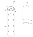
도 1은 본 발명의 제1 실시예에 따른 이차전지를 예시적으로 나타낸 단면도이다. 1 is a cross-sectional view showing a secondary battery according to a first embodiment of the present invention by way of example.
도 1을 참고하면, 본 발명의 제1 실시예에 따른 이차전지(100)는 양극(112), 분리막(114), 음극(111)이 교대로 적층된 전극 조립체(110)와, 전극 조립체(110)를 수용하는 캔(120), 및 전극 조립체(110)의 권취 중심부에 위치되는 센터 핀(130)을 포함한다.Referring to FIG. 1, the
이하에서, 도 1 내지 도 6을 참조하여, 본 발명의 제1 실시예인 전극 조립체에 대해 보다 상세히 설명하기로 한다. Hereinafter, an electrode assembly that is a first embodiment of the present invention will be described in more detail with reference to FIGS. 1 to 6.
도 1을 참고하면, 이차전지(100)는 전극 조립체(110) 및 전극 조립체(110)를 수용하는 캔(120)을 포함한다. 여기서, 이차전지(100)는 전극 조립체(110)와 함께 캔(120)에 수용되는 전해액을 더 포함할 수 있다.Referring to FIG. 1, the
캔(120)은 제1 캔(121) 및 제2 캔(122)을 포함하여 전극 조립체(110)를 내부에 수용할 수 있다. The
또한, 제1 캔(121)에 음극(111)의 단부가 접속되고, 제2 캔(122)의 단부에 양극(112)의 단부가 접속될 수 있지만, 본 발명이 여기에 반드시 한정되는 것은 아니며, 예를 들어 제1 캔(121)에 양극(112)의 단부가 접속되고, 제2 캔(122)에 음극(111)의 단부가 접속될 수 있음은 물론이다.In addition, although the end of the
아울러, 제1 캔(121) 및 제2 캔(122)은 예를 들어 상호 마주보는 방향으로 개구된 통형으로 형성될 수도 있다. 이때, 캔(120)은 제1 캔(121) 및 제2 캔(122) 사이의 중첩 부분을 절연하는 절연체(123)를 더 포함할 수 있다. In addition, the first can 121 and the
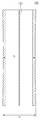
도 2는 본 발명의 제1 실시예에 따른 이차전지에서 전극 조립체를 나타낸 사시도이고, 도 3은 본 발명의 제1 실시예에 따른 이차전지에서 전극 조립체를 권취하기 전 펼쳐진 상태를 나타낸 평면도이다.2 is a perspective view showing an electrode assembly in the secondary battery according to the first embodiment of the present invention, and FIG. 3 is a plan view showing an unfolded state before winding the electrode assembly in the secondary battery according to the first embodiment of the present invention.
도 1 내지 도 3을 참고하면, 전극 조립체(110)는 충방전이 가능한 발전소자로서, 전극(113)과 분리막(114)이 결집되어 교대로 적층된 구조를 형성한다. 여기서, 전극 조립체(110)는 권취된 형태를 가질 수 있다. 1 to 3, the
전극(113)은 양극(112) 및 음극(111)을 포함할 수 있다. 그리고, 분리막(114)은 양극(112) 및 음극(111)을 분리하여 전기적으로 절연시킨다. 여기서, 양극(112) 및 음극(111)은 시트(Sheet) 형태로 형성되어 분리막(114)과 함께 권취되고, 젤리 롤(Jelly roll) 형으로 형성될 수 있다. 이때, 전극 조립체(110)는 예를 들어 원기둥 형태로 권취될 수 있다. 그리고, 양극(112), 분리막(114), 및 음극(111)은 전극 조립체(110)의 권취 중심축(S)에 대하여 수직인 전극 조립체(110)의 두께 방향으로 각각 다수의 겹(Layer)을 형성할 수 있다.The
음극(111)은 음극 집전체(111a) 및 음극 집전체(111a)에 도포된 음극 활물질(111b)을 포함할 수 있다. The
또한, 음극(111)은 음극 집전체(111a)에 음극 활물질(111b)이 도포되지 않은 영역인 음극 무지부(111c)가 형성될 수 있다.In addition, the
음극 무지부(111c)는 예를 들어 전극 조립체(110)의 권취 중심축(S) 방향을 기준으로, 분리막(114) 보다 더 돌출되도록 일측(S1) 방향 단부에 위치될 수 있다. The negative electrode uncoated
또한, 음극 무지부(111c)는 권취 방향을 따라 음극(111)의 일측 단부 전체에서 형성될 수 있다.In addition, the negative electrode uncoated
아울러, 음극 무지부(111c)는 전극 조립체(110)의 권취 중심축(S)에서 일측(S1) 방향으로 양극(112)의 단부 보다 더 연장되어 형성될 수 있다. 즉, 예를 들어 도 1에 도시된 사항을 참고로 할 때 음극 무지부(111c) 영역의 음극 집전체(111a) 단부가 양극(112) 보다 전극 조립체(110)의 상부 방향으로 더 돌출형성될 수 있다. 따라서, 상부에 위치되는 제1 캔(121)의 내측 상면과 직접 접촉되어 제1 캔(121)이 음극 단자를 형성할 수 있다. 이에 따라, 음극(111)의 단부가 제1 캔(121)에 직접 접촉되어 별도의 연결선을 통해 연결되는 것에 비하여 저항이 현저히 감소되고, 결국 위치별 열편차에 의한 특정부위의 열화 방지 및 전체 열을 낮추어 열화에 의한 전지(cell)성능 퇴화를 방지할 수 있다.In addition, the negative electrode
음극 집전체(111a)는 예를 들어 구리(Cu) 또는 니켈(Ni) 재질로 이루어진 포일(foil)로 이루어질 수 있다. 음극 활물질(111b)은 예를 들어 인조흑연, 리튬금속, 리튬합금, 카본, 석유코크, 활성화 카본, 그래파이트, 실리콘 화합물, 주석 화합물, 티타늄 화합물 또는 이들의 합금으로 이루어질 수 있다. 이때, 음극 활물질(111b)은 예를 들어 비흑연계의 SiO(silica, 실리카) 또는 SiC(silicon carbide, 실리콘카바이드) 등이 더 포함되어 이루어질 수 있다.The negative electrode
양극(112)은 양극 집전체(112a) 및 양극 집전체(112a)에 도포된 양극 활물질(112b)을 포함할 수 있다. The
또한, 양극(112)은 양극 집전체(112a)에 양극 활물질(112b)이 도포되지 않은 영역인 양극 무지무(112c)가 형성될 수 있다.In addition, the
양극 무지무(112c)는 예를 들어 전극 조립체(110)의 권취 중심축(S) 방향을 기준으로, 분리막(114) 보다 더 돌출되도록 타측(S2) 방향 단부에 위치될 수 있다.The
또한, 양극 무지부(112c)는 권취 방향을 따라 양극(112)의 타측 단부 전체에서 형성될 수 있다.In addition, the positive electrode
아울러, 양극 무지부(112c)는 전극 조립체(110)의 권취 중심축(S)에서 일측(S1) 방향으로 음극(111)의 단부 보다 더 연장되어 형성될 수 있다. 즉, 예를 들어 도 1에 도시된 사항을 참고로 할 때 양극 무지부(112c) 영역의 양극 집전체(112a) 단부가 음극(111) 보다 전극 조립체(110)의 하부 방향으로 더 돌출 형성될 수 있다. 따라서, 예를 들어 하부에 위치되는 제2 캔(122)의 내측 하면과 직접 접촉되어 제2 캔(122)이 양극 단자를 형성할 수 있다. 이에 따라, 양극(112)의 단부가 제2 캔(122)에 직접 접촉되어 별도의 연결선을 통해 연결되는 것에 비하여 저항이 현저히 감소되고, 결국 위치별 열편차에 의한 특정부위의 열화 방지 및 전체 열을 낮추어 열화에 의한 전지(cell)성능 퇴화를 방지할 수 있다.In addition, the positive electrode
이처럼 본원발명의 제1 실시예에 따른 이차전지(100)에서, 전극 조립체(110)의 모든 전극(113)은 연속적으로 캔(120)과 직접 연결될 수 있어 전극(113)의 위치별 저항과 온도 편차를 줄일 수 있다.In this way, in the
양극 집전체(112a)는 예를 들어 알루미늄 재질의 포일(Foil)로 이루어질 수 있고, 양극 활물질(112b)은 예를 들어 리튬망간산화물, 리튬코발트산화물, 리튬니켈산화물, 리튬인산철, 또는 이들 중 1종 이상이 포함된 화합물 및 혼합물 등으로 이루어질 수 있다. The positive electrode
분리막(114)은 절연 재질로 이루어져 양극(112) 및 음극(111)과 교대로 적층된다. 여기서, 분리막(114)은 양극(112) 및 음극(111) 사이와, 양극(112) 및 음극(111)의 외측면에 위치될 수 있다. 이때, 분리막(114)은 전극 조립체(110)의 권취 시 폭방향(W)으로 최외각에도 위치될 수 있다.The
또한, 분리막(114)은 연성이 있는 재질로 이루어질 수 있다. 이때, 분리막(114)은 예를 들어 미다공성을 가지는 폴리에칠렌, 폴리프로필렌 등 폴리올레핀계 수지막으로 형성될 수 있다. In addition, the
도 4는 본 발명의 제1 실시예에 따른 이차전지에서 센터 핀을 나타낸 사시도이고, 도 5는 도 4에서 A-A'선을 따라 절개한 단면도이며, 도 6은 도 4에서 B-B'선을 따라 절개한 단면도이다.4 is a perspective view showing a center pin in the secondary battery according to the first embodiment of the present invention, FIG. 5 is a cross-sectional view taken along line A-A' in FIG. 4, and FIG. 6 is B-B' in FIG. It is a cross-sectional view cut along the line.
도 1 내지 도 4를 참고하면, 센터 핀(130)은 전극 조립체(110)의 권취 중심부에 위치되어 전극 조립체(110)의 권취 시 기준축 또는 기준면을 제공할 수 있다. 여기서, 전극 조립체(110)는 센터 핀(130)을 감싸며 센터 핀(130)을 기준으로 권취될 수 있다. 이에 따라, 양극(112), 분리막(114), 및 음극(111)의 권취 시, 센터 핀(130)을 통해 양극(112), 분리막(114), 및 음극(111)의 사행정렬도를 잡아줄 수 있다(참고로, 사행은 권취 시 고르게 말리지 않고 경사지게 말리는 현상을 의미한다). Referring to FIGS. 1 to 4, the
또한, 센터 핀(130)이 전극 조립체(110)의 중심부인 코어부에 구비되어, 충방전 사이클(Cycle) 진행에 따라 전극 조립체(110)의 코어부에 위치된 전극(113)의 깨짐 발생을 방지할 수 있다.In addition, the
아울러, 양극(112), 분리막(114), 및 음극(111)은 센터 핀(130)의 외주면에 권취되어, 전극 조립체(110)의 권취 중심축(S)에 대하여 수직인 전극 조립체(110)의 두께 방향으로 각각 다수의 겹(Layer)을 형성할 수 있다.In addition, the
한편, 전극 조립체(110)는 센터 핀(130)에 테이프(Tape)(150)로 고정된 채로 권취될 수 있다. 테이프 고정 방식을 이용할 경우 권취 시의 사행정렬도는 더욱 좋아질 수 있다.Meanwhile, the
그리고, 센터 핀(130)은 절연 재질을 포함하여 형성될 수 있다.In addition, the
또한, 센터 핀(130)의 길이는 전극 조립체(110)의 권취 중심축(S) 방향으로 음극 무지부(111c)의 일측 단부에서 양극 무지부(112c)의 타측 단부 까지의 길이 보다 짧게 형성될 수 있다. 여기서, 음극 무지부(111c)는 권취 중심축(S)을 기준으로 센터 핀(130) 보다 일측(S1) 방향으로 더 길게 연장형성되고, 양극 무지부(112c)가 권취 중심축(S)을 기준으로 센터 핀(130) 보다 타측(S2) 방향으로 더 길게 연장 형성될 수 있다.In addition, the length of the
아울러, 센터 핀(130)의 일측부가 제1 캔(221)의 내면에 면접촉하고, 센터 핀(130)의 타측부가 제2 캔(222)의 내면에 면접촉할 수 있다.In addition, one side of the
그리고, 센터 핀(130)은 중심축을 기준으로 중앙측이 비어있는 통형 형태로 구비될 수 있다. 여기서, 센터 핀(130)은 예를 들어 원통형으로 형성되고, 센터 핀(130)의 내,외측 사이를 전해액 또는 가스 등의 유체가 통과할 수 있도록 측면을 관통하는 유동홀(131)이 적어도 하나 이상 형성될 수 있다. In addition, the
유동홀(131)은 예를 들어 다수개의 사각홀 또는 원형홀로 형성될 수 있다.The
또한, 유동홀(131)은 예를 들어 센터 핀(130)에 다수의 열과 행으로 형성될 수 있다. 여기서, 유동홀(131)은 구체적으로 예를 들어 4열로 형성되어 센터 핀(130)이 폭방향(W)에 대해 4방향에 각각 형성되고, 아울러 4행으로 형성되어 센터 핀(130)의 길이방향(L)을 따라 각행이 일정간격 이격되며 형성될 수 있다. 이때, 유동홀(131)은 예를 들어 한 쌍으로 형성되고, 한 쌍의 유동홀(131)이 센터 핀(130)에 다수의 열과 행으로 형성될 수 있다.Also, the
또한, 도 1 및 도 4 내지 도 6을 참고하면, 센터 핀(130)은 내주면을 가로지르는 크로스 바(Cross bar)(132)를 더 구비할 수 있다.In addition, referring to FIGS. 1 and 4 to 6, the
따라서, 센터 핀(130)은 크로스 바(132)에 지지되어 전극 조립체(110)의 스웰링(Sweelling)에 따른 가압력이 센터 핀(130)에 전해질 때 센터 핀(130)이 파손되지 않을 수 있다. 여기서, 전극 조립체(110)의 권취하기위해 센터 핀(130)을 돌리는 맨드릴(Mandrel) 등의 권취 장치(10)가 크로스 바(132)와 센터 핀(130)의 내측면 사이의 공간에 억지끼움 결합되어 센터 핀(130)을 회전시킬 수 있다. 이때, 권취 장치에 구비된 한 쌍의 지그(11,12)는 예를 들어 센터 핀(130)에서 크로스 바(132)와 센터 핀(130)의 내측면 사이의 공간에 억지끼움 결합되어 센터 핀(130)을 용이하게 회전시킬 수 있다. 특히, 센터 핀(130)의 길이가 전극 조립체(110) 보다 짧은 경우에도, 권취 장치(10)가 센터 핀(130)에 용이하게 결합되며 센터 핀(130)을 회전시킬 수 있어, 전극 조립체(110)의 권취가 현저히 용이할 수 있다. 즉, 센터 핀(130)의 원통형 공간에 권취 장치(10)가 삽입되어 센터 핀(130)을 회전 시 센터 핀(130)이 헛도는 슬립(Spip)현상이 발생될 수 있으나, 센터 핀(130)에 크로스 바(132)가 더 구비되면 권취 장치(10)에 구비된 한 쌍의 지그(11,12)가 크로스 바(132)와 센터 핀(130)의 내측면 사이의 공간에 억지끼움 결합됨과 동시에 크로스 바(132)를 파지할 수 있어 센터 핀(130)이 헛도는 슬립(Spip)현상을 방지할 수 있다.Accordingly, the
아울러, 센터 핀(130)은 센터 핀(130)의 길이방향(L)으로 양단부의 외주면 지름(a) 보다 중앙부의 외주면 지름(b)이 작게 형성된다. 이때, 센터 핀(130)은 외주면의 지름이 센터 핀(130)의 길이방향(L)을 따라 양단부에서 중앙부로 갈수록 점차 작아지는 테이퍼(Taper) 형태로 형성될 수 있다. In addition, the
이에 따라, 양극(112), 분리막(114), 및 음극(111)의 권취 시, 센터 핀(130)을 통해 양극(112), 분리막(114), 및 음극(111)의 사행정렬도를 보다 우수하게 잡아줄 수 있다. 여기서, 전극(113)의 권취 시 전극 조립체(110)에 전극 활물질이 도포되지 않은 양측의 두께를 보상해주며 권취시킬 수 있어 사행에 우수할 수 있다. 또한, 양극(112)이 음극(111) 보다 권취 중심축(S) 방향으로 길이가 작을 때, 권취 시 양극(112)이 없고 음극(111)만 존재하는 부분의 두께를 보상해주며 권취시킬 수 있어 사행에 보다 우수할 수 있다.Accordingly, when winding the
이하에서는 제2 실시예에 따른 이차전지를 설명하기로 한다.Hereinafter, the secondary battery according to the second embodiment will be described.
도 7은 본 발명의 제2 실시예에 따른 이차전지를 예시적으로 나타낸 단면도이다. 7 is a cross-sectional view showing a secondary battery according to a second embodiment of the present invention by way of example.
도 7을 참고하면, 본 발명의 제2 실시예에 따른 이차전지(200)는 양극(112), 분리막(114), 음극(111)이 교대로 적층된 전극 조립체(110)와, 전극 조립체(110)를 수용하는 캔(120), 및 전극 조립체(110)의 권취 중심부에 위치되는 센터 핀(230)을 포함한다.Referring to FIG. 7, a
본 발명의 제2 실시예에 따른 이차전지(200)는 전술한 제1 실시예에 따른 이차전지와 비교할 때, 센터 핀(230)의 구성에 대하여 차이가 있다. 따라서, 본 실시예는 제1 실시예와 중복되는 내용은 간략히 기술하고, 차이점을 중심으로 기술하도록 한다.The
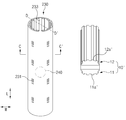
도 8은 본 발명의 제2 실시예에 따른 이차전지에서 센터 핀을 나타낸 사시도이고, 도 9 는 도 8에서 C-C'선을 따라 절개한 단면도이며, 도 10 은 도 8에서 D-D'선을 따라 절개한 단면도이다.8 is a perspective view showing a center pin in a secondary battery according to a second embodiment of the present invention, FIG. 9 is a cross-sectional view taken along line C-C' in FIG. 8, and FIG. 10 is D-D' in FIG. It is a cross-sectional view cut along the line.
도 7 및 도 8을 참고하면, 본 발명의 제2 실시예에 따른 이차전지(200)에서 센터 핀(230)은 전극 조립체(110)의 권취 중심부에 위치되어, 전극 조립체(110)의 권취 시 기준축 또는 기준면을 제공할 수 있다. 여기서, 전극 조립체(110)는 센터 핀(230)을 감싸며 센터 핀(230)을 기준으로 권취될 수 있다. Referring to FIGS. 7 and 8, in the
아울러, 센터 핀(230)은 원통형으로 형성되고, 센터 핀(230)의 내,외측 사이를 전해액 또는 가스 등의 유체가 통과할 수 있도록 측면을 관통하는 유동홀(231)이 적어도 하나 이상 형성될 수 있다. 이때, 유동홀(231)은 예를 들어 다수개의 사각홀 또는 원형홀로 형성될 수 있다.In addition, the
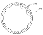
그리고, 도 8 및 도 9을 참고하면, 센터 핀(230)은 내주면을 따라 다수개의 슬립(Slip) 방지홈(233)이 센터 핀(230)의 길이방향(L)으로 더 형성될 수 있다. 여기서, 센터 핀(230)은 폭 방향(W)의 횡단면이 오목부와 볼록부가 반복되는 톱니 형태로 형성될 수 있다. 이때, 톱니 형태는 센터 핀(230)의 횡단면에서 내측에 형성될 수 있다.In addition, referring to FIGS. 8 and 9, the
결국, 센터 핀(230)의 내주면을 따라 다수개의 슬립 방지홈(233)이 형성되어, 전극 조립체(110)를 권취시키는 권취 장치(10')가 센터 핀(230)의 내측에 삽입 시 슬립(Slip) 현상이 발생되는 것을 방지할 수 있다.As a result, a plurality of
즉, 센터 핀(230)의 원통형 공간에 권취 장치(10')가 삽입되어 센터 핀(230)을 회전시킬때 센터 핀(230)이 헛도는 슬립(Spip)현상이 발생될 수 있으나, 센터 핀(230)의 내주면을 따라 다수개의 슬립 방지홈(233)이 톱니 형태로 더 형성되어, 권취 장치(10')에 구비된 한 쌍의 지그(11',12')가 센터 핀(230)의 내측에 억지끼움 결합됨과 동시에 한 쌍의 지그(11',12')의 외면이 센터 핀(230)의 톱니 형태의 내주면에 밀착되어, 센터 핀(230)이 헛도는 슬립(Spip)현상을 방지할 수 있다. 여기서, 예를 들어 한 쌍의 지그(11',12')의 외면이 센터 핀(230)의 톱니 형태의 내주면에 대응되는 형태로 형성되어, 센터 핀(230)이 헛도는 슬립(Spip)현상을 보다 효과적으로 방지할 수 있다. 이때, 한 쌍의 지그(11',12')의 외면은 센터 핀(230)의 톱니 형태의 내주면에 대응되는 요철부(11a',12b')가 형성될 수 있다.That is, when the winding device 10' is inserted into the cylindrical space of the
한편, 도 7, 도 8 및 도 10을 참고하면, 본 발명의 제2 실시예에 따른 이차전지(200)에서 센터 핀(230)은 내부 공간에 위치되는 가스 볼(Gas ball)(240)을 더 포함할 수 있다. 여기서, 가스 볼(240)은 소화 약제 가스(Gas)(241) 및 소화 약제 가스(241)를 둘러싸는 필름(Film)(242)을 포함할 수 있다. 이때, 필름(242)은 폴리머(Polymer) 재질을 포함하여 이루어질 수 있다.Meanwhile, referring to FIGS. 7, 8 and 10, in the
이에 따라, 센터 핀(230)의 내측에 폴리머 필름으로 둘러싸인 가스 볼(240)이, 전지 내부 온도가 상승으로 인한 고열 발생 시 폴리머 필름이 녹으며 소화 약제 가스(241)가 노출되며 소화약제(fire extinguishing agent)기능을 발현할 수 있고, 이로 인해 전지의 발화를 방지할 수 있다. Accordingly, the
한편, 가스 볼(240)은 전해액(E)의 수위에 따라 위치가 변동되어, 가스 볼(240)의 높이에 따라 전해액(E) 함침 정도를 판별할 수 있다. 이때, 전해액(E) 주액 후 캔(120) 내부의 일정량의 전해액(E)이 전극 조립체(110)로 함침됨에 따라 전해액(E)이 수위가 낮아지게 되고, 엑스레이(X-ray) 검사 등으로 가스 볼(240)의 높낮이 검사를 통해 함침 정도를 판별할 수 있다.On the other hand, the position of the
도 11은 본 발명의 실시예에 따른 전지 팩을 정면에서 투시하여 예시적으로 나타낸 도면이다. 11 is a view exemplarily showing a battery pack according to an embodiment of the present invention when viewed from the front.
도 1 및 도 11을 참고하면, 본 발명의 실시예에 따른 전지 팩(1000)은 다수개의 이차전지(100) 및 팩 케이스(1010)를 포함하는 전지 팩(1000)으로서, 이차전지(100)는 양극(112), 분리막(114), 음극(111)이 교대로 적층된 전극 조립체(110)과, 전극 조립체(110)를 수용하는 캔(120), 및 전극 조립체(110)의 권취 중심부에 위치되는 센터 핀(130)을 포함한다. 여기서, 전극 조립체(110)는 센터 핀(130)을 감싸며 권취되며, 센터 핀(130)은 원통형으로 형성되고, 센터 핀(130)의 내,외측 사이를 유체가 통과할 수 있도록 측면을 관통하는 유동홀(132)이 적어도 하나 이상 형성될 수 있다.1 and 11, the
본 발명의 실시예에 따른 전지 팩(1000)은 전술한 제1 실시예에 따른 이차전지 또는 제2 실시예에 따른 이차전지를 포함하는 전지 팩(1000)이다. 따라서, 본 실시예는 전술한 실시예와 중복되는 내용은 간략히 기술하고, 차이점을 중심으로 기술하도록 한다.The
보다 상세히, 본 발명의 실시예에 따른 전지 팩(1000)은 다수개의 이차전지(100) 및 다수개의 이차전지(100)를 수용하는 팩 케이스(1010)를 포함한다. 여기서, 팩 케이스(1010)는 다수개의 이차전지(100)를 수용하는 수용부가 내부에 형성될 수 있다.In more detail, the
또한, 전지 팩(1000)은 다수개의 이차전지(100)를 전기적으로 연결하는 단자부(1040)를 더 포함할 수 있다. 이때, 단자부(1040)는 다수개의 이차전지(100)의 음극 단자들을 연결하는 음극 단자부(1020) 및 양극 단자들을 연결하는 양극 단자부(1030) 를 포함할 수 있다. 여기서, 단자부(1040)는 예를 들어 다수개의 이차전지(100)를 직렬 또는 병렬 연결할 수 있다.In addition, the
이상 본 발명을 구체적인 실시예를 통하여 상세히 설명하였으나, 이는 본 발명을 구체적으로 설명하기 위한 것으로, 본 발명에 따른 이차전지 및 이를 포함하는 전지 팩은 이에 한정되지 않는다. 본 발명의 기술적 사상 내에서 당해 분야의 통상의 지식을 가진 자에 의해 다양한 실시가 가능하다고 할 것이다. The present invention has been described in detail through specific examples, but this is for specifically describing the present invention, and the secondary battery and the battery pack including the same according to the present invention are not limited thereto. It will be said that various implementations are possible by those skilled in the art within the technical spirit of the present invention.
또한, 발명의 구체적인 보호 범위는 첨부된 특허청구범위에 의하여 명확해질 것이다. In addition, the specific protection scope of the invention will be clarified by the appended claims.
100,200: 이차전지
110: 전극 조립체
111: 음극
112: 양극
113: 전극
114: 분리막
120: 캔
121: 제1 캔
122: 제2 캔
130,230: 센터 핀
131,231: 유동홀
132: 크로스 바
233: 슬립 방지홈
240: 가스 볼
241: 소화 약제 가스
242: 필름100,200: secondary battery
110: electrode assembly
111: cathode
112: anode
113: electrode
114: separator
120: can
121: first can
122: second can
130, 230: Center pin
131,231: floating hall
132: cross bar
233: slip prevention groove
240: gas ball
241: fire extinguishing agent gas
242: film
Claims (14)
상기 전극 조립체를 수용하는 캔; 및
상기 전극 조립체의 권취 중심부에 위치되는 센터 핀을 포함하고,
상기 전극 조립체는 상기 센터 핀을 감싸며 권취되며,
상기 센터 핀은 원통형으로 형성되고, 상기 센터 핀의 내,외측 사이를 유체가 통과할 수 있도록 측면을 관통하는 유동홀이 적어도 하나 이상 형성되는 이차전지.An electrode assembly in which an anode, a separator and a cathode are alternately stacked;
A can accommodating the electrode assembly; And
It includes a center pin located in the center of the winding of the electrode assembly,
The electrode assembly is wound around the center pin,
The center pin is formed in a cylindrical shape, and a secondary battery in which at least one flow hole passing through a side surface is formed to allow fluid to pass between the inner and outer sides of the center pin.
상기 음극은 음극 활물질이 코팅되지 않는 음극 무지부가, 상기 전극 적층체의 권취 중심축 방향을 기준으로, 상기 분리막 보다 더 돌출되도록 일측 방향 단부에 위치되며,
상기 양극은 양극 활물질이 코팅되지 않는 양극 무지부가, 상기 전극 적층체의 권취 중심축 방향을 기준으로, 상기 분리막 보다 더 돌출되도록 타측 방향 단부에 위치되고,
상기 캔은 제1 캔 및 제2 캔을 포함하고,
상기 음극 무지부는 상기 제1 캔에 직접 접촉하고, 상기 양극 무지부는 상기 제2 캔의 내면에 직접 접촉하는 이차전지.The method according to claim 1,
The negative electrode is a negative electrode non-coated negative electrode active material is located at one end in one direction so as to protrude more than the separator, based on the winding axis direction of the electrode stack,
The positive electrode is a positive electrode non-coated positive electrode active material is located on the other end so as to protrude more than the separator, based on the direction of the central axis of the winding of the electrode stack,
The can includes a first can and a second can,
The negative electrode non-coated portion directly contacts the first can, and the positive electrode non-coated portion directly contacts the inner surface of the second can.
상기 음극 무지부는 권취 방향을 따라 상기 음극의 일측 단부 전체에서 형성되어 있고,
상기 양극 무지부는 권취 방향을 따라 상기 양극의 타측 단부 전체에서 형성되어 있는 이차전지.The method according to claim 2,
The negative electrode non-coated portion is formed on the entirety of one end of the negative electrode along the winding direction,
The positive electrode uncoated portion is a secondary battery formed in the entire other end of the positive electrode along the winding direction.
상기 센터 핀의 길이는,
상기 음극 무지부의 일측 단부에서 상기 양극 무지부의 타측 단부의 길이 보다 짧게 형성되는 이차전지.The method according to claim 2,
The length of the center pin,
A secondary battery formed shorter than the length of the other end of the positive electrode uncoated portion at one end of the negative electrode uncoated portion.
상기 유동홀은 다수개의 사각홀 또는 원형홀로 형성되는 이차전지.The method according to any one of claims 1 to 4,
The flow hole is a secondary battery formed of a plurality of square holes or circular holes.
상기 센터 핀은 내주면을 가로지르는 크로스 바(Cross bar)가 더 구비되는 이차전지.The method according to any one of claims 1 to 4,
The center pin is a secondary battery that is further provided with a cross bar (Cross bar) across the inner peripheral surface.
상기 센터 핀은,
외주면의 지름이 상기 센터 핀의 길이방향을 따라 양단부에서 중앙부로 갈수록 점차 작아지는 테이퍼 형태로 형성되는 이차전지.The method according to any one of claims 1 to 4,
The center pin,
A secondary battery formed in a tapered shape in which the diameter of the outer circumferential surface gradually decreases from both ends to the center along the longitudinal direction of the center pin.
상기 센터 핀은 절연 재질을 포함하는 이차전지.The method according to any one of claims 1 to 4,
The center pin is a secondary battery comprising an insulating material.
상기 센터 핀은,
내주면을 따라 다수개의 슬립(Slip) 방지홈이 상기 센터 핀의 길이방향을 따라 더 형성되는 이차전지.The method according to any one of claims 1 to 4,
The center pin,
A secondary battery in which a plurality of slip prevention grooves along the inner circumferential surface are further formed along the longitudinal direction of the center pin.
상기 센터 핀은,
폭 방향의 횡단면이 오목부와 볼록부가 반복되는 톱니 형태를 포함하는 이차전지.The method according to claim 9,
The center pin,
A secondary battery having a sawtooth shape in which a concave portion and a convex portion are repeated in a cross section in the width direction.
상기 톱니 형태는 상기 센터 핀의 횡단면에서 내측에 형성되는 이차전지.The method according to claim 10,
The saw-tooth shape is a secondary battery formed on the inner side in the cross section of the center pin.
상기 센터 핀은 내부 공간에 가스 볼을 더 포함하고,
상기 가스 볼은
소화 약제 가스(Gas); 및
상기 소화 약제 가스를 둘러싸는 필름을 포함하는 이차전지.The method according to any one of claims 1 to 4,
The center pin further includes a gas ball in the interior space,
The gas ball
Fire extinguishing agent gas (Gas); And
A secondary battery comprising a film surrounding the extinguishing agent gas.
상기 필름은 폴리머 재질을 포함하는 이차전지.The method according to claim 12,
The film is a secondary battery comprising a polymer material.
상기 이차전지는,
양극, 분리막, 음극이 교대로 적층된 전극 조립체;
상기 전극 조립체를 수용하는 캔; 및
상기 전극 조립체의 권취 중심부에 위치되는 센터 핀을 포함하고,
상기 전극 조립체는 상기 센터 핀을 감싸며 권취되며,
상기 센터 핀은 원통형으로 형성되고, 상기 센터 핀의 내,외측 사이를 유체가 통과할 수 있도록 측면을 관통하는 유동홀이 적어도 하나 이상 형성되는 전지 팩. A battery pack comprising a plurality of secondary batteries and a pack case accommodating the plurality of secondary batteries,
The secondary battery,
An electrode assembly in which an anode, a separator and a cathode are alternately stacked;
A can accommodating the electrode assembly; And
It includes a center pin located in the center of the winding of the electrode assembly,
The electrode assembly is wound around the center pin,
The center pin is formed in a cylindrical shape, the battery pack is formed at least one flow hole through the side surface so that the fluid can pass between the inside and outside of the center pin.
Priority Applications (1)
| Application Number | Priority Date | Filing Date | Title |
|---|---|---|---|
| KR1020180156109A KR20200069026A (en) | 2018-12-06 | 2018-12-06 | Rechargeable battery and battery pack comprising the same |
Applications Claiming Priority (1)
| Application Number | Priority Date | Filing Date | Title |
|---|---|---|---|
| KR1020180156109A KR20200069026A (en) | 2018-12-06 | 2018-12-06 | Rechargeable battery and battery pack comprising the same |
Publications (1)
| Publication Number | Publication Date |
|---|---|
| KR20200069026A true KR20200069026A (en) | 2020-06-16 |
Family
ID=71141954
Family Applications (1)
| Application Number | Title | Priority Date | Filing Date |
|---|---|---|---|
| KR1020180156109A KR20200069026A (en) | 2018-12-06 | 2018-12-06 | Rechargeable battery and battery pack comprising the same |
Country Status (1)
| Country | Link |
|---|---|
| KR (1) | KR20200069026A (en) |
Cited By (1)
| Publication number | Priority date | Publication date | Assignee | Title |
|---|---|---|---|---|
| CN117832649A (en) * | 2024-03-04 | 2024-04-05 | 江苏睿恩新能源科技有限公司 | Cylindrical battery winding core with high energy density design and cylindrical battery |
Citations (1)
| Publication number | Priority date | Publication date | Assignee | Title |
|---|---|---|---|---|
| KR20160010121A (en) | 2014-07-18 | 2016-01-27 | 주식회사 엘지화학 | Jelly-roll type electrode assembly |
-
2018
- 2018-12-06 KR KR1020180156109A patent/KR20200069026A/en unknown
Patent Citations (1)
| Publication number | Priority date | Publication date | Assignee | Title |
|---|---|---|---|---|
| KR20160010121A (en) | 2014-07-18 | 2016-01-27 | 주식회사 엘지화학 | Jelly-roll type electrode assembly |
Cited By (1)
| Publication number | Priority date | Publication date | Assignee | Title |
|---|---|---|---|---|
| CN117832649A (en) * | 2024-03-04 | 2024-04-05 | 江苏睿恩新能源科技有限公司 | Cylindrical battery winding core with high energy density design and cylindrical battery |
Similar Documents
| Publication | Publication Date | Title |
|---|---|---|
| KR102480958B1 (en) | Rechargeable battery | |
| US8481196B2 (en) | Multi-layered type electrochemistry cell of improved safety | |
| US7897279B2 (en) | Jelly-roll type electrode assembly and secondary battery including the same | |
| JP2004119383A (en) | Electrode assembly of lithium ion battery, and lithium ion battery using it | |
| US7754376B2 (en) | Cylindrical lithium secondary battery and method of fabricating the same | |
| EP4270565A1 (en) | Electrode assembly and secondary battery comprising same | |
| EP3849004B1 (en) | Secondary battery | |
| KR20200069026A (en) | Rechargeable battery and battery pack comprising the same | |
| US20230275314A1 (en) | Secondary Battery | |
| JP7193200B2 (en) | secondary battery | |
| US20220376321A1 (en) | Electrode assembly and secondary battery comprising the same | |
| KR102141123B1 (en) | Electrode assembly | |
| US20230198042A1 (en) | Electrode assembly and secondary battery comprising the same | |
| KR20220073669A (en) | Electrode assembly and rechargeable battery comprising the same | |
| KR20230096735A (en) | Rechargeable battery and battery pack comprising the same | |
| KR102255528B1 (en) | Electrode assembly | |
| KR20240030811A (en) | Electrode assembly and secondary battery including the same | |
| CN117642905A (en) | Clamp for evaluating safety of secondary battery | |
| KR20180026046A (en) | Electrode assembly | |
| KR20180111324A (en) | Electrode assembly |