EP3848918B1 - System und verfahren zur steuerung von elektronischen vorrichtungen - Google Patents
System und verfahren zur steuerung von elektronischen vorrichtungen Download PDFInfo
- Publication number
- EP3848918B1 EP3848918B1 EP20150803.3A EP20150803A EP3848918B1 EP 3848918 B1 EP3848918 B1 EP 3848918B1 EP 20150803 A EP20150803 A EP 20150803A EP 3848918 B1 EP3848918 B1 EP 3848918B1
- Authority
- EP
- European Patent Office
- Prior art keywords
- electronic devices
- ultra
- electronic device
- wideband
- remote
- Prior art date
- Legal status (The legal status is an assumption and is not a legal conclusion. Google has not performed a legal analysis and makes no representation as to the accuracy of the status listed.)
- Active
Links
Images



Classifications
-
- G—PHYSICS
- G08—SIGNALLING
- G08C—TRANSMISSION SYSTEMS FOR MEASURED VALUES, CONTROL OR SIMILAR SIGNALS
- G08C17/00—Arrangements for transmitting signals characterised by the use of a wireless electrical link
- G08C17/02—Arrangements for transmitting signals characterised by the use of a wireless electrical link using a radio link
-
- G—PHYSICS
- G01—MEASURING; TESTING
- G01S—RADIO DIRECTION-FINDING; RADIO NAVIGATION; DETERMINING DISTANCE OR VELOCITY BY USE OF RADIO WAVES; LOCATING OR PRESENCE-DETECTING BY USE OF THE REFLECTION OR RERADIATION OF RADIO WAVES; ANALOGOUS ARRANGEMENTS USING OTHER WAVES
- G01S3/00—Direction-finders for determining the direction from which infrasonic, sonic, ultrasonic or electromagnetic waves, or particle emission, not having a directional significance, are being received
- G01S3/02—Direction-finders for determining the direction from which infrasonic, sonic, ultrasonic or electromagnetic waves, or particle emission, not having a directional significance, are being received using radio waves
- G01S3/04—Details
- G01S3/043—Receivers
-
- G—PHYSICS
- G01—MEASURING; TESTING
- G01S—RADIO DIRECTION-FINDING; RADIO NAVIGATION; DETERMINING DISTANCE OR VELOCITY BY USE OF RADIO WAVES; LOCATING OR PRESENCE-DETECTING BY USE OF THE REFLECTION OR RERADIATION OF RADIO WAVES; ANALOGOUS ARRANGEMENTS USING OTHER WAVES
- G01S5/00—Position-fixing by co-ordinating two or more direction or position line determinations; Position-fixing by co-ordinating two or more distance determinations
- G01S5/02—Position-fixing by co-ordinating two or more direction or position line determinations; Position-fixing by co-ordinating two or more distance determinations using radio waves
- G01S5/0257—Hybrid positioning
- G01S5/0258—Hybrid positioning by combining or switching between measurements derived from different systems
- G01S5/02585—Hybrid positioning by combining or switching between measurements derived from different systems at least one of the measurements being a non-radio measurement
-
- G—PHYSICS
- G08—SIGNALLING
- G08C—TRANSMISSION SYSTEMS FOR MEASURED VALUES, CONTROL OR SIMILAR SIGNALS
- G08C2201/00—Transmission systems of control signals via wireless link
- G08C2201/70—Device selection
Definitions
- the present disclosure relates to a control system for controlling electronic devices. Furthermore, the present disclosure relates to a corresponding control method for controlling electronic devices, and to a corresponding computer program.
- Electronic devices such as televisions and radios, may be controlled by remote control units.
- These remote-control units may be universal in the sense that they are able to control a plurality of different electronic devices instead of being suited exclusively for controlling a single type of electronic device.
- these remote-control units are universal, it is important to select a specific electronic device among a plurality of candidate electronic devices, before the remote-control units can be used. This selection should be performed in accordance with the intention of the user.
- a communication device comprises: first to third antennas arranged to be spaced different distances from each other; first to third transceiving units; and a processor for controlling the first to third transceiving units, wherein the processor calculates a first phase difference on the basis of a difference between a first reception signal received by the first antenna and a second reception signal received by the second antenna, calculates a second phase difference on the basis of a difference between the first reception signal received by the first antenna and a third reception signal received by the third antenna, and calculates location information of an external communication device on the basis of the first phase difference and the second phase difference.
- US 2019/180609 A1 describes a control object and a method for controlling a plurality of pieces of equipment.
- the method includes determining, with the control object, a piece of equipment to be controlled from the plurality of pieces of equipment based on a user pointing the control object at the piece of equipment to be controlled, adapting, with the control object, a control interface of the control object as a function of the piece of equipment to be controlled, receiving, through the control interface of the control object, at least one command from the user to control the piece of equipment to be controlled, generating, with the control object, control data configured to control the piece of equipment to be controlled based on the at least one command received from the user, and controlling the piece of equipment to be controlled by transmitting the control data with the control object.
- US 2015/264506 A1 describes a method of configuring an audio system comprising one or more speaker units, which comprises: transmitting radio signals from at least a first location indicating a first speaker unit position, and from a second location indicating a second speaker unit position or a user position; receiving the signals at an antenna of the audio system; calculating an angle of arrival of the signals at the antenna; calculating the relative positions of the first and second locations based at least partially on the angle of arrival; and configuring the audio system based on the relative positions of the first and second locations.
- a control system for controlling electronic devices, as defined in claim 1.
- the processing unit is configured to select, as said specific electronic device, the electronic device from which the ultra-wideband signal having the smallest angle of arrival is received.
- control system further comprises an inertial measurement unit, wherein the processing unit is further configured to select said specific electronic device using said angle of arrival as well as measurement data provided by the inertial measurement unit.
- the further communication comprises transmitting one or more functional commands to the selected specific electronic device.
- the electronic devices comprise a plurality of ultra-wideband antennas.
- the number of ultra-wideband antennas is three.
- the electronic devices comprise a localization unit, wherein said localization unit is configured to determine a relative position of the electronic devices with regard to the ultra-wideband communication unit using the ultra-wideband antennas.
- a control method for controlling electronic devices is conceived, as defined in claim 9.
- the processing unit selects, as said specific electronic device, the electronic device from which the ultra-wideband signal having the smallest angle of arrival is received.
- a computer program comprising executable instructions that, when executed by a control system for controlling electronic devices, cause said control system to carry out a method of the kind set forth.
- Electronic devices such as televisions, radios and game consoles, may be controlled by remote control units.
- These remote-control units may be universal in the sense that they are able to control a plurality of different electronic devices instead of being suited exclusively for controlling a single type of electronic device.
- these remote-control units are universal, it is important to select a specific electronic device among a plurality of candidate electronic devices, before the remote-control units can be used. This selection should be performed in accordance with the intention of the user.
- remote-control units In particular, many consumer electronic devices require the knowledge of their associated remote-control unit or gaming pad in order to translate a user movement in a three-dimensional space into actual commands in the console or consumer electronic device.
- universal remote-control units are widely used, they have the limitation that a targeted device - i.e., a device that the user intends to control by means of the remote-control unit - should be selected before it can be controlled.
- remote control units typically contain an inertial measurement unit (IMU), such an IMU does not provide enough information to determine the position of the remote-control units. As a result, it may be difficult to perform a correct selection of a targeted device.
- IMU inertial measurement unit
- Fig. 1 shows an example of orientation sensing 100.
- Many remote-control units for example for smart televisions, contain an inertial measurement unit (IMU) for offering a better user experience of controlling the targeted device.
- IMU inertial measurement unit
- a typical IMU contains three sensors: an angular rate sensor, a magnetometer and an accelerometer.
- the angular rate sensor is configured to track rotatory movements.
- the magnetometer measures the direction of the magnetic field, which provides an absolute orientation with regard to the magnetic field of the earth.
- the accelerometer is used for tracking linear accelerations.
- Fig. 1 shows a remote-control unit 102 that contains such an IMU (not shown), which is measuring its orientation with the magnetic field as a reference.
- a drawback of the IMU is that it cannot be used for an accurate position determination of the remote-control unit, because of the drift of the linear acceleration sensor (i.e., the accelerometer).
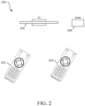
- Fig. 2 shows an example of a control system 200.
- the system comprises a remote-control unit which is universal in the sense that it is able to control different types of electronic devices.
- the remote-control unit is able to control at least a television 206 and a radio 208.
- the remote-control unit may be held by a user at different positions 202, 204. These positions reflect the intention of the user to select a specific electronic device for further communication. For example, at the first position 202 the user intends to control the television 206, while at the second location 204 the user intends to control the radio 208.
- it may be difficult to perform a correct selection of a targeted device i.e. to perform a selection which is in accordance with with the intention of the user.
- a single remote-control unit may be used for controlling the television 206 and the radio 208.
- the device 206, 208 that is selected by the remote-control unit should be the device the remote points at.
- the remote-control unit at "Remote position 1" 202 points at the television 206 and the remote-control unit at "Remote position 2" 204 points at the radio 208.
- the remote-control unit has the same orientation with regard to the magnetic field in both positions 202, 204. As a result, no accurate position determination can be performed using the IMU, and as a consequence, the targeted device 206, 208 might not be selected correctly.
- RSSI received signal strength indicator
- Fig. 3 shows an illustrative embodiment of a control system 300.
- the control system 300 comprises an ultra-wideband (UWB) communication unit 302 and a processing unit 304 which are operatively coupled to each other.
- the UWB communication unit 302 is configured to receive UWB signals from electronic devices (not shown).
- the processing unit 304 is configured to select a specific electronic device among the electronic devices for further communication. Furthermore, the processing unit 304 is configured to select the specific electronic device using an angle of arrival of the UWB signals received from the electronic devices. In this way, a correct selection of a targeted device is facilitated.
- Fig. 4 shows an illustrative embodiment of a control method 400 for controlling electronic devices.
- the control method 400 comprises the following steps: at 402, receiving, by a UWB communication unit, ultra-wideband signals from electronic devices, and at 404, selecting, by a processing unit, a specific electronic device among said electronic devices for further communication, wherein the processing unit selects said specific electronic device using an angle of arrival of the ultra-wideband signals received from the electronic devices.
- a processing unit selects said specific electronic device using an angle of arrival of the ultra-wideband signals received from the electronic devices.
- Fig. 5 shows another illustrative embodiment of a control system 500.
- the system 500 comprises a remote-control unit 502 which is configured to control a first electronic device 504 (a television) and a second electronic device 506 (a radio). Before either one of the electronic devices 504, 506 can be controlled, the targeted electronic device should be selected.
- the electronic device 504, 506 is selected which has transmitted an ultra-wideband signal that is received with the smallest angle of arrival by the remote-control unit 502. Thus, if the angle ⁇ is smaller than the angle ⁇ , then the first electronic device 504 is selected, and if the angle ⁇ is smaller than the angle ⁇ , then the second electronic device 506 is selected.
- Fig. 5 shows a remote-control unit 502 that contains a UWB interface. Using this UWB interface, the remote-control unit 502 measures the angle of arrival of the UWB signals that are emitted by the first electronic device 504 and the second electronic device 506. The signal emitted by the first electronic device 504 is received from the angle ⁇ and the signal emitted by the second electronic device 506 is received from the angle ⁇ . Since users will usually point at a dedicated device with the remote-control unit 502, the ambiguity can be neglected because the smallest angle determines the selected device. In the scenario shown in Fig.
- the remote-control unit 502 can be moved and the angles will change according to the movement because the angles of the received signals are measured instead of the orientation of the remote-control unit 502.
- a two-dimensional device selection can be performed using the UWB interface.
- the measurement data of an inertial measurement unit can be combined with the UWB measurement data.
- the first electronic device 502 may be placed above the second electronic device 504, but have the same x- and y-coordinates, such that the angle ⁇ is substantially equal to ⁇ .
- Fig. 6 shows an example of a control system 600.
- the system 600 comprises a remote-control unit 602, a first electronic device 604 and a second electronic device 606.
- the first electronic device 604 (television) is placed above the second electronic device 606 (radio).
- the remote-control unit 602 points at the first electronic device 604 (television).
- the orientation of the remote-control unit 602 is measured by an inertial measurement unit (not shown) integrated into the remote-control unit 602.
- the angle of arrival measured by the UWB interface of the remote-control unit 602 is substantially the same for the first electronic device 604 and the second electronic device 606, because they have the same x- and y-coordinates.
- the electronic devices 604, 606 comprise a plurality of ultra-wideband antennas. Thereby, a correct selection of a targeted device is also facilitated if the position of the electronic devices only differs in the z-direction.
- the number of ultra-wideband antennas is three.
- the electronic devices 604, 606 comprise a localization unit (not shown), which is configured to determine a relative position of the electronic devices with regard to the ultra-wideband communication unit using the ultra-wideband antennas. In this way, the position of the remote-control unit 602 relative to the first electronic device 604 and the second electronic device 606 can easily be determined.
- Fig. 7 shows an illustrative embodiment of an electronic device 700.
- the electronic devices comprises a plurality of UWB antennas 704.
- the electronic device 702 (television) contains three UWB antennas, which have known positions. Because of the known positions of the antennas two incoming angles can be measured, for example the vertical and the horizontal angle. Thus, by combining the angle of arrival measurements around these two axes with a UWB distance measurement, the relative position of the remote-control unit with regard to the electronic device 702 can be determined. It is noted that the positions of the antennas 704 are only examples. In principle, all antenna positions that enable the system to calculate the signal angles around two axes can be chosen.
- Fig. 7 is a relatively simple arrangement, comprising a vertical and a horizontal antenna pair with a distance of ⁇ /2 between the antennas, wherein ⁇ represents the wavelength of the antennas.
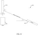
- Fig. 8 shows a control system 800.
- the processing unit is configured to determine a first vertical angle, which is a vertical angle of arrival of a UWB signal transmitted by the UWB communication unit to the electronic devices, and the electronic devices are configured to determine a second vertical angle, which is a vertical angle of arrival of the same UWB signal as it is received by the electronic devices. This further facilitates the correct selection of a targeted device.
- the processing unit is configured to select the specific electronic device if the first vertical angle has a predefined correlation with the second vertical angle.
- the control system 800 shown in Fig. 8 comprises a remote-control unit 802 which is configured to control a first electronic device 804 (television) and a second electronic device 806 (radio).
- Fig. 8 shows that the television 804 measures the vertical angle of the incoming signal that was emitted by the remote-control unit 802.
- the orientation data of the IMU of the remote-control unit 802 with the measured angle of arrival and time of flight at the side of the television 804, the direction in which the remote-control unit 802 points can be determined.
- the angle ⁇ is measured by the television 804; this angle determines the vertical angle of the incoming signal.
- the angle ⁇ is measured by the remote-control unit 802 and determines the vertical orientation of the remote-control unit 802 relative to the magnetic and gravitational field.
- the probability that the remote-control unit 802 points at the television 804 is high.
- the horizontal angles can be compared in an analogous way.
- the horizontal and vertical angle measurements can be performed simultaneously using three receiver units. Alternatively, two subsequent measurements may be performed using, for example, two receiver units and an antenna switch.
- the remote-control unit 802 does not need to perform an angle of arrival measurement if the television 804 contains three antennas. If the remote-control unit 802 has a horizontally orientated antenna pair only the vertical pair of the antenna is needed on the television's side in order to determine the pointing direction. However, by using a vertical antenna pair in the television 804 and a horizontal antenna pair in the remote-control unit 802 the redundancy will be lost. As a result, the measurement accuracy may decrease if the remote-control unit's antenna axis is moved in such a way that the television's and remote-control unit's antenna axes are no longer orthogonal. Only one device with three antennas may be needed, because this device can measure the position of all the other devices in the room.
- This position can be used for calculating the incoming angles from the remote-control unit 802 to all the other devices.
- the decision on which device should react on the remote signal should be made by the remote-control unit 802 if the controlled devices, for example the television 804 and the radio 806, do not communicate with each other. If each device takes a decision autonomously, unwanted behavior may be the result, because each device may take different and inconsistent actions. If all the devices communicate with each other, the decision can be made by a central controlling device which could be either one of the controlled devices 804, 806 or the remote-control unit 802 itself.
- the transmission of the data can be carried out either by the UWB interface or another, out-of-band communication channel, which may be supported by the devices.
- an out-of-band communication channel may result in less communication on the UWB channel, which will result in a higher channel capacity on the UWB side.
- a three-dimensional line-of-sight signal can be estimated by using a three-antenna system, which tracks the position of an emitter by combining angle-of-arrival and time-of-flight measurements, and the direction of the signal can be estimated by combining the determined position with the orientation data of the remote-control unit 802.
- an advantage of an UWB-based system is that the remote-control unit 802 does not need a direct line of sight with the controlled devices 804, 806, because the RF signal can be still received through interposed objects.
- the systems and methods described herein may at least partially be embodied by a computer program or a plurality of computer programs, which may exist in a variety of forms both active and inactive in a single computer system or across multiple computer systems.
- they may exist as software program(s) comprised of program instructions in source code, object code, executable code or other formats for performing some of the steps.
- Any of the above may be embodied on a computer-readable medium, which may include storage devices and signals, in compressed or uncompressed form.
- the term "computer” refers to any electronic device comprising a processor, such as a general-purpose central processing unit (CPU), a specific-purpose processor or a microcontroller.
- a computer is capable of receiving data (an input), of performing a sequence of predetermined operations thereupon, and of producing thereby a result in the form of information or signals (an output).
- the term "computer” will mean either a processor in particular or more generally a processor in association with an assemblage of interrelated elements contained within a single case or housing.
- processor or “processing unit” refers to a data processing circuit that may be a microprocessor, a co-processor, a microcontroller, a microcomputer, a central processing unit, a field programmable gate array (FPGA), a programmable logic circuit, and/or any circuit that manipulates signals (analog or digital) based on operational instructions that are stored in a memory.
- memory refers to a storage circuit or multiple storage circuits such as read-only memory, random access memory, volatile memory, non-volatile memory, static memory, dynamic memory, Flash memory, cache memory, and/or any circuit that stores digital information.
- a "computer-readable medium” or “storage medium” may be any means that can contain, store, communicate, propagate, or transport a computer program for use by or in connection with the instruction execution system, apparatus, or device.
- the computer-readable medium may be, for example but not limited to, an electronic, magnetic, optical, electromagnetic, infrared, or semiconductor system, apparatus, device, or propagation medium.
- the computer-readable medium may include the following: an electrical connection having one or more wires, a portable computer diskette, a random-access memory (RAM), a read-only memory (ROM), an erasable programmable read-only memory (EPROM or Flash memory), an optical fiber, a portable compact disc read-only memory (CDROM), a digital versatile disc (DVD), a Blu-ray disc (BD), and a memory card.
- RAM random-access memory
- ROM read-only memory
- EPROM or Flash memory erasable programmable read-only memory
- CDROM compact disc read-only memory
- DVD digital versatile disc
- BD Blu-ray disc
Landscapes
- Physics & Mathematics (AREA)
- Engineering & Computer Science (AREA)
- General Physics & Mathematics (AREA)
- Radar, Positioning & Navigation (AREA)
- Remote Sensing (AREA)
- Computer Networks & Wireless Communication (AREA)
- Selective Calling Equipment (AREA)
- Details Of Television Systems (AREA)
Claims (11)
- Steuersystem (300) zum Steuern elektronischer Vorrichtungen, wobei das Steuersystem (300) die elektronischen Vorrichtungen und die folgenden Komponenten umfasst, die in eine Fernsteuereinheit integriert sind:eine Ultrabreitband-Kommunikationseinheit (302), die ausgelegt ist zum Empfangen von Ultrabreitbandsignalen von den elektronischen Vorrichtungen; undeine Verarbeitungseinheit (304), die ausgelegt ist zum Auswählen einer spezifischen elektronischen Vorrichtung unter den elektronischen Vorrichtungen für eine weitere Kommunikation;wobei die Verarbeitungseinheit (304) ausgelegt ist zum Auswählen der spezifischen elektronischen Vorrichtung unter Verwendung eines Ankunftswinkels der Ultrabreitbandsignale, die von den elektronischen Vorrichtungen empfangen werden;dadurch gekennzeichnet, dass die Verarbeitungseinheit (304) ferner ausgelegt ist zum Bestimmen eines ersten Vertikalwinkels, bei dem es sich um einen vertikalen Ankunftswinkel eines Ultrabreitbandsignals handelt, das durch die Ultrabreitband-Kommunikationseinheit (302) an die elektronischen Vorrichtungen übertragen wird, und wobei die elektronischen Vorrichtungen ausgelegt sind zum Bestimmen eines zweiten Vertikalwinkels, bei dem es sich um einen vertikalen Ankunftswinkel des Ultrabreitbandsignals handelt, wie durch die elektronischen Vorrichtungen empfangen;wobei die Verarbeitungseinheit (304) ferner ausgelegt ist zum Auswählen der spezifischen elektronischen Vorrichtung, falls der erste Vertikalwinkel eine vordefinierte Korrelation mit dem zweiten Vertikalwinkel aufweist.
- Steuersystem (300) nach Anspruch 1, wobei die Verarbeitungseinheit (304) ausgelegt ist zum Auswählen, als die spezifische elektronische Vorrichtung, der elektronischen Vorrichtung, von der das Ultrabreitbandsignal mit dem kleinsten Ankunftswinkel empfangen wird.
- Steuersystem (300) nach einem vorstehenden Anspruch, ferner umfassend eine inertiale Messeinheit, wobei die Verarbeitungseinheit (304) ferner ausgelegt ist zum Auswählen der spezifischen elektronischen Vorrichtung unter Verwendung des Ankunftswinkels sowie Messdaten, die durch die inertiale Messeinheit bereitgestellt werden.
- Steuersystem (300) nach einem vorstehenden Anspruch, wobei die weitere Kommunikation das Übertragen eines oder mehrerer Funktionsbefehle an die ausgewählte spezifische elektronische Vorrichtung umfasst.
- Steuersystem (300) nach einem vorstehenden Anspruch, wobei die elektronischen Vorrichtungen eine Vielzahl von Ultrabreitbandantennen umfassen.
- Steuersystem (300) nach Anspruch 5, wobei die Anzahl von Ultrabreitbandantennen drei beträgt.
- Steuersystem (300) nach Anspruch 5 oder 6, wobei die elektronischen Vorrichtungen eine Lokalisierungseinheit umfassen, wobei die Lokalisierungseinheit ausgelegt ist zum Bestimmen einer relativen Position der elektronischen Vorrichtungen bezüglich der Ultrabreitband-Kommunikationseinheit unter Verwendung der Ultrabreitbandantennen.
- Steuersystem (300) nach einem vorstehenden Anspruch, wobei die vordefinierte Korrelation durch die Gleichung δ + 90° = ε repräsentiert wird, wobei δ den ersten Vertikalwinkel repräsentiert und ε den zweiten Vertikalwinkel repräsentiert.
- Steuerverfahren (400) zum Steuern elektronischer Vorrichtungen, wobei das Steuerverfahren (400) umfasst:Empfangen, durch eine Ultrabreitband-Kommunikationseinheit (302), die in eine Fernsteuereinheit integriert ist, von Ultrabreitbandsignalen von den elektronischen Vorrichtungen; undAuswählen, durch eine Verarbeitungseinheit (304), die in die Fernsteuereinheit integriert ist, einer spezifischen elektronischen Vorrichtung unter den elektronischen Vorrichtungen für eine weitere Kommunikation;wobei die Verarbeitungseinheit (304) die spezifische elektronische Vorrichtung unter Verwendung eines Ankunftswinkels der Ultrabreitbandsignale auswählt, die von den elektronischen Vorrichtungen empfangen werden;dadurch gekennzeichnet, dass die Verarbeitungseinheit (304) einen ersten Vertikalwinkel bestimmt, bei dem es sich um einen vertikalen Ankunftswinkel eines Ultrabreitbandsignals handelt, das durch die Ultrabreitband-Kommunikationseinheit (302) an die elektronischen Vorrichtungen übertragen wird, und wobei die elektronischen Vorrichtungen einen zweiten Vertikalwinkel bestimmen, bei dem es sich um einen vertikalen Ankunftswinkel des Ultrabreitbandsignals handelt, wie durch die elektronischen Vorrichtungen empfangen;wobei die Verarbeitungseinheit (304) die spezifische elektronische Vorrichtung auswählt, falls der erste Vertikalwinkel eine vordefinierte Korrelation mit dem zweiten Vertikalwinkel aufweist.
- Steuerverfahren (400) nach Anspruch 9, wobei die Verarbeitungseinheit (304), als die spezifische elektronische Vorrichtung, die elektronische Vorrichtung auswählt, von der das Ultrabreitbandsignal mit dem kleinsten Ankunftswinkel empfangen wird.
- Computerprogramm, das ausführbare Anweisungen umfasst, die bei Ausführung durch ein Steuersystem (300) zum Steuern elektronischer Vorrichtungen bewirken, dass das Steuersystem (300) das Verfahren (400) nach Anspruch 9 oder 10 ausführt.
Priority Applications (2)
| Application Number | Priority Date | Filing Date | Title |
|---|---|---|---|
| EP20150803.3A EP3848918B1 (de) | 2020-01-08 | 2020-01-08 | System und verfahren zur steuerung von elektronischen vorrichtungen |
| US17/141,329 US11501633B2 (en) | 2020-01-08 | 2021-01-05 | System and method for controlling electronic devices |
Applications Claiming Priority (1)
| Application Number | Priority Date | Filing Date | Title |
|---|---|---|---|
| EP20150803.3A EP3848918B1 (de) | 2020-01-08 | 2020-01-08 | System und verfahren zur steuerung von elektronischen vorrichtungen |
Publications (2)
| Publication Number | Publication Date |
|---|---|
| EP3848918A1 EP3848918A1 (de) | 2021-07-14 |
| EP3848918B1 true EP3848918B1 (de) | 2024-10-02 |
Family
ID=69156228
Family Applications (1)
| Application Number | Title | Priority Date | Filing Date |
|---|---|---|---|
| EP20150803.3A Active EP3848918B1 (de) | 2020-01-08 | 2020-01-08 | System und verfahren zur steuerung von elektronischen vorrichtungen |
Country Status (2)
| Country | Link |
|---|---|
| US (1) | US11501633B2 (de) |
| EP (1) | EP3848918B1 (de) |
Families Citing this family (2)
| Publication number | Priority date | Publication date | Assignee | Title |
|---|---|---|---|---|
| CN117441199A (zh) * | 2021-09-16 | 2024-01-23 | 三星电子株式会社 | 利用uwb的遥控系统和方法 |
| EP4262095A1 (de) | 2022-04-12 | 2023-10-18 | Nxp B.V. | Kommunikationsvorrichtung und verfahren zum betrieb |
Family Cites Families (14)
| Publication number | Priority date | Publication date | Assignee | Title |
|---|---|---|---|---|
| US7206559B2 (en) * | 2001-10-16 | 2007-04-17 | Hewlett-Packard Development Company, L.P. | System and method for a mobile computing device to control appliances |
| JP5886205B2 (ja) * | 2010-11-25 | 2016-03-16 | パナソニック インテレクチュアル プロパティ コーポレーション オブアメリカPanasonic Intellectual Property Corporation of America | 通信機器 |
| FR2980005A1 (fr) * | 2011-09-09 | 2013-03-15 | Movea | Procede de controle d'un curseur par des mesures d'attitude d'un pointeur et pointeur mettant en oeuvre ledit procede |
| US9699586B2 (en) * | 2012-10-02 | 2017-07-04 | Nokia Technologies Oy | Configuring a sound system |
| FR3024267B1 (fr) * | 2014-07-25 | 2017-06-02 | Redlime | Procedes de determination et de commande d'un equipement a commander, dispositif, utilisation et systeme mettant en œuvre ces procedes |
| US9536421B2 (en) * | 2015-06-02 | 2017-01-03 | Qualcomm Technologies International, Ltd. | Intuitive way to point, access and control appliances and other objects in building interiors |
| KR102513379B1 (ko) * | 2015-12-18 | 2023-03-22 | 엘지전자 주식회사 | 통신 장치 및 이를 구비하는 전자기기 |
| US9740307B2 (en) * | 2016-01-08 | 2017-08-22 | Movea | Processing unit, computer program amd method to control a cursor on a screen according to an orientation of a pointing device |
| KR102401641B1 (ko) * | 2016-01-08 | 2022-05-25 | 엘지전자 주식회사 | 모바일 디바이스 및 모바일 디바이스의 제어방법 |
| US10708876B2 (en) * | 2017-03-23 | 2020-07-07 | Legic Identsystem Ag | System and method for determining location information for a mobile radio transmitter |
| TWI628631B (zh) * | 2017-05-08 | 2018-07-01 | 和碩聯合科技股份有限公司 | 遙控系統、遙控方法與閘道器 |
| US11320509B2 (en) * | 2018-04-17 | 2022-05-03 | Apple Inc. | Electronic devices with motion sensing and angle of arrival detection circuitry |
| EP3910460B1 (de) * | 2018-09-28 | 2023-07-19 | Apple Inc. | Vorschlag von empfängern auf basis von nähe |
| US20210349177A1 (en) * | 2020-05-08 | 2021-11-11 | 7hugs Labs SAS | Low profile pointing device |
-
2020
- 2020-01-08 EP EP20150803.3A patent/EP3848918B1/de active Active
-
2021
- 2021-01-05 US US17/141,329 patent/US11501633B2/en active Active
Also Published As
| Publication number | Publication date |
|---|---|
| US11501633B2 (en) | 2022-11-15 |
| US20210209935A1 (en) | 2021-07-08 |
| EP3848918A1 (de) | 2021-07-14 |
Similar Documents
| Publication | Publication Date | Title |
|---|---|---|
| US10534067B2 (en) | Radio frequency communication system | |
| US11057742B2 (en) | Methods for facilitating a relative position determination | |
| US10922956B2 (en) | Device and method for controlling a plurality of targeted devices | |
| US9482741B1 (en) | System and method of locating a radio frequency (RF) tracking device using a calibration routine | |
| US20170079001A1 (en) | Radio Beacon for Direction Detection | |
| US12353643B2 (en) | Low profile pointing device sensor fusion | |
| US20130053061A1 (en) | Terminal, localization system, and method for determining location | |
| EP3328100B1 (de) | Verfahren und vorrichtung zur befehlsübertragung basierend auf einer anzeigerichtung, intelligente vorrichtung und speichermedium | |
| KR102268566B1 (ko) | 통합 플랫폼을 사용한 로컬라이제이션 | |
| US9949082B2 (en) | Mobile terminal device, location search method, and computer-readable recording medium | |
| US20210349177A1 (en) | Low profile pointing device | |
| US11914005B2 (en) | Method and apparatus for automatic frequency selection in magnetic tracking systems | |
| US11501633B2 (en) | System and method for controlling electronic devices | |
| JP6704570B1 (ja) | 位置検出システム、位置特定装置及び位置特定プログラム | |
| JP2017067565A (ja) | 端末装置および測位プログラム | |
| GB2445384A (en) | Determining the position of a signal source | |
| US11150321B2 (en) | System for orientation estimation from radio measurements | |
| CN101194528A (zh) | 定位系统和定位方法以及移动位置数据发送器 | |
| KR102157879B1 (ko) | 격벽구조를 갖는 실내 공간 내에서의 측위 시스템 및 방법 | |
| JP2017067566A (ja) | 端末装置および検出プログラム | |
| US11262432B2 (en) | Positioning apparatus and positioning method | |
| US20230028930A1 (en) | System and method for computing a distance-based relative direction | |
| US20240192347A1 (en) | Method of operating a uwb radar device | |
| EP4474848A1 (de) | Vorrichtung zur verfolgung eines objekts | |
| US20220044353A1 (en) | System and method for reducing jitter when providing an indication for a relative direction of another device |
Legal Events
| Date | Code | Title | Description |
|---|---|---|---|
| PUAI | Public reference made under article 153(3) epc to a published international application that has entered the european phase |
Free format text: ORIGINAL CODE: 0009012 |
|
| STAA | Information on the status of an ep patent application or granted ep patent |
Free format text: STATUS: THE APPLICATION HAS BEEN PUBLISHED |
|
| AK | Designated contracting states |
Kind code of ref document: A1 Designated state(s): AL AT BE BG CH CY CZ DE DK EE ES FI FR GB GR HR HU IE IS IT LI LT LU LV MC MK MT NL NO PL PT RO RS SE SI SK SM TR |
|
| STAA | Information on the status of an ep patent application or granted ep patent |
Free format text: STATUS: REQUEST FOR EXAMINATION WAS MADE |
|
| 17P | Request for examination filed |
Effective date: 20220114 |
|
| RBV | Designated contracting states (corrected) |
Designated state(s): AL AT BE BG CH CY CZ DE DK EE ES FI FR GB GR HR HU IE IS IT LI LT LU LV MC MK MT NL NO PL PT RO RS SE SI SK SM TR |
|
| STAA | Information on the status of an ep patent application or granted ep patent |
Free format text: STATUS: EXAMINATION IS IN PROGRESS |
|
| 17Q | First examination report despatched |
Effective date: 20240205 |
|
| GRAP | Despatch of communication of intention to grant a patent |
Free format text: ORIGINAL CODE: EPIDOSNIGR1 |
|
| STAA | Information on the status of an ep patent application or granted ep patent |
Free format text: STATUS: GRANT OF PATENT IS INTENDED |
|
| INTG | Intention to grant announced |
Effective date: 20240711 |
|
| GRAS | Grant fee paid |
Free format text: ORIGINAL CODE: EPIDOSNIGR3 |
|
| GRAA | (expected) grant |
Free format text: ORIGINAL CODE: 0009210 |
|
| STAA | Information on the status of an ep patent application or granted ep patent |
Free format text: STATUS: THE PATENT HAS BEEN GRANTED |
|
| AK | Designated contracting states |
Kind code of ref document: B1 Designated state(s): AL AT BE BG CH CY CZ DE DK EE ES FI FR GB GR HR HU IE IS IT LI LT LU LV MC MK MT NL NO PL PT RO RS SE SI SK SM TR |
|
| REG | Reference to a national code |
Ref country code: GB Ref legal event code: FG4D |
|
| REG | Reference to a national code |
Ref country code: CH Ref legal event code: EP |
|
| REG | Reference to a national code |
Ref country code: DE Ref legal event code: R096 Ref document number: 602020038552 Country of ref document: DE |
|
| REG | Reference to a national code |
Ref country code: IE Ref legal event code: FG4D |
|
| REG | Reference to a national code |
Ref country code: LT Ref legal event code: MG9D |
|
| REG | Reference to a national code |
Ref country code: NL Ref legal event code: MP Effective date: 20241002 |
|
| REG | Reference to a national code |
Ref country code: AT Ref legal event code: MK05 Ref document number: 1729046 Country of ref document: AT Kind code of ref document: T Effective date: 20241002 |
|
| PG25 | Lapsed in a contracting state [announced via postgrant information from national office to epo] |
Ref country code: NL Free format text: LAPSE BECAUSE OF FAILURE TO SUBMIT A TRANSLATION OF THE DESCRIPTION OR TO PAY THE FEE WITHIN THE PRESCRIBED TIME-LIMIT Effective date: 20241002 |
|
| PG25 | Lapsed in a contracting state [announced via postgrant information from national office to epo] |
Ref country code: NL Free format text: LAPSE BECAUSE OF FAILURE TO SUBMIT A TRANSLATION OF THE DESCRIPTION OR TO PAY THE FEE WITHIN THE PRESCRIBED TIME-LIMIT Effective date: 20241002 |
|
| PG25 | Lapsed in a contracting state [announced via postgrant information from national office to epo] |
Ref country code: PT Free format text: LAPSE BECAUSE OF FAILURE TO SUBMIT A TRANSLATION OF THE DESCRIPTION OR TO PAY THE FEE WITHIN THE PRESCRIBED TIME-LIMIT Effective date: 20250203 Ref country code: HR Free format text: LAPSE BECAUSE OF FAILURE TO SUBMIT A TRANSLATION OF THE DESCRIPTION OR TO PAY THE FEE WITHIN THE PRESCRIBED TIME-LIMIT Effective date: 20241002 Ref country code: IS Free format text: LAPSE BECAUSE OF FAILURE TO SUBMIT A TRANSLATION OF THE DESCRIPTION OR TO PAY THE FEE WITHIN THE PRESCRIBED TIME-LIMIT Effective date: 20250202 |
|
| PG25 | Lapsed in a contracting state [announced via postgrant information from national office to epo] |
Ref country code: FI Free format text: LAPSE BECAUSE OF FAILURE TO SUBMIT A TRANSLATION OF THE DESCRIPTION OR TO PAY THE FEE WITHIN THE PRESCRIBED TIME-LIMIT Effective date: 20241002 |
|
| PG25 | Lapsed in a contracting state [announced via postgrant information from national office to epo] |
Ref country code: BG Free format text: LAPSE BECAUSE OF FAILURE TO SUBMIT A TRANSLATION OF THE DESCRIPTION OR TO PAY THE FEE WITHIN THE PRESCRIBED TIME-LIMIT Effective date: 20241002 |
|
| PG25 | Lapsed in a contracting state [announced via postgrant information from national office to epo] |
Ref country code: ES Free format text: LAPSE BECAUSE OF FAILURE TO SUBMIT A TRANSLATION OF THE DESCRIPTION OR TO PAY THE FEE WITHIN THE PRESCRIBED TIME-LIMIT Effective date: 20241002 |
|
| PG25 | Lapsed in a contracting state [announced via postgrant information from national office to epo] |
Ref country code: NO Free format text: LAPSE BECAUSE OF FAILURE TO SUBMIT A TRANSLATION OF THE DESCRIPTION OR TO PAY THE FEE WITHIN THE PRESCRIBED TIME-LIMIT Effective date: 20250102 |
|
| PG25 | Lapsed in a contracting state [announced via postgrant information from national office to epo] |
Ref country code: AT Free format text: LAPSE BECAUSE OF FAILURE TO SUBMIT A TRANSLATION OF THE DESCRIPTION OR TO PAY THE FEE WITHIN THE PRESCRIBED TIME-LIMIT Effective date: 20241002 Ref country code: LV Free format text: LAPSE BECAUSE OF FAILURE TO SUBMIT A TRANSLATION OF THE DESCRIPTION OR TO PAY THE FEE WITHIN THE PRESCRIBED TIME-LIMIT Effective date: 20241002 Ref country code: GR Free format text: LAPSE BECAUSE OF FAILURE TO SUBMIT A TRANSLATION OF THE DESCRIPTION OR TO PAY THE FEE WITHIN THE PRESCRIBED TIME-LIMIT Effective date: 20250103 |
|
| PG25 | Lapsed in a contracting state [announced via postgrant information from national office to epo] |
Ref country code: PL Free format text: LAPSE BECAUSE OF FAILURE TO SUBMIT A TRANSLATION OF THE DESCRIPTION OR TO PAY THE FEE WITHIN THE PRESCRIBED TIME-LIMIT Effective date: 20241002 Ref country code: CZ Free format text: LAPSE BECAUSE OF FAILURE TO SUBMIT A TRANSLATION OF THE DESCRIPTION OR TO PAY THE FEE WITHIN THE PRESCRIBED TIME-LIMIT Effective date: 20241002 |
|
| PG25 | Lapsed in a contracting state [announced via postgrant information from national office to epo] |
Ref country code: RS Free format text: LAPSE BECAUSE OF FAILURE TO SUBMIT A TRANSLATION OF THE DESCRIPTION OR TO PAY THE FEE WITHIN THE PRESCRIBED TIME-LIMIT Effective date: 20250102 |
|
| PG25 | Lapsed in a contracting state [announced via postgrant information from national office to epo] |
Ref country code: SM Free format text: LAPSE BECAUSE OF FAILURE TO SUBMIT A TRANSLATION OF THE DESCRIPTION OR TO PAY THE FEE WITHIN THE PRESCRIBED TIME-LIMIT Effective date: 20241002 |
|
| REG | Reference to a national code |
Ref country code: DE Ref legal event code: R097 Ref document number: 602020038552 Country of ref document: DE |
|
| PG25 | Lapsed in a contracting state [announced via postgrant information from national office to epo] |
Ref country code: DK Free format text: LAPSE BECAUSE OF FAILURE TO SUBMIT A TRANSLATION OF THE DESCRIPTION OR TO PAY THE FEE WITHIN THE PRESCRIBED TIME-LIMIT Effective date: 20241002 |
|
| PG25 | Lapsed in a contracting state [announced via postgrant information from national office to epo] |
Ref country code: EE Free format text: LAPSE BECAUSE OF FAILURE TO SUBMIT A TRANSLATION OF THE DESCRIPTION OR TO PAY THE FEE WITHIN THE PRESCRIBED TIME-LIMIT Effective date: 20241002 |
|
| PG25 | Lapsed in a contracting state [announced via postgrant information from national office to epo] |
Ref country code: RO Free format text: LAPSE BECAUSE OF FAILURE TO SUBMIT A TRANSLATION OF THE DESCRIPTION OR TO PAY THE FEE WITHIN THE PRESCRIBED TIME-LIMIT Effective date: 20241002 |
|
| PG25 | Lapsed in a contracting state [announced via postgrant information from national office to epo] |
Ref country code: SK Free format text: LAPSE BECAUSE OF FAILURE TO SUBMIT A TRANSLATION OF THE DESCRIPTION OR TO PAY THE FEE WITHIN THE PRESCRIBED TIME-LIMIT Effective date: 20241002 |
|
| PG25 | Lapsed in a contracting state [announced via postgrant information from national office to epo] |
Ref country code: IT Free format text: LAPSE BECAUSE OF FAILURE TO SUBMIT A TRANSLATION OF THE DESCRIPTION OR TO PAY THE FEE WITHIN THE PRESCRIBED TIME-LIMIT Effective date: 20241002 |
|
| P01 | Opt-out of the competence of the unified patent court (upc) registered |
Free format text: CASE NUMBER: APP_29881/2025 Effective date: 20250623 |
|
| PLBE | No opposition filed within time limit |
Free format text: ORIGINAL CODE: 0009261 |
|
| STAA | Information on the status of an ep patent application or granted ep patent |
Free format text: STATUS: NO OPPOSITION FILED WITHIN TIME LIMIT |
|
| REG | Reference to a national code |
Ref country code: CH Ref legal event code: PL |
|
| PG25 | Lapsed in a contracting state [announced via postgrant information from national office to epo] |
Ref country code: SE Free format text: LAPSE BECAUSE OF FAILURE TO SUBMIT A TRANSLATION OF THE DESCRIPTION OR TO PAY THE FEE WITHIN THE PRESCRIBED TIME-LIMIT Effective date: 20241002 |
|
| 26N | No opposition filed |
Effective date: 20250703 |
|
| PG25 | Lapsed in a contracting state [announced via postgrant information from national office to epo] |
Ref country code: LU Free format text: LAPSE BECAUSE OF NON-PAYMENT OF DUE FEES Effective date: 20250108 Ref country code: MC Free format text: LAPSE BECAUSE OF FAILURE TO SUBMIT A TRANSLATION OF THE DESCRIPTION OR TO PAY THE FEE WITHIN THE PRESCRIBED TIME-LIMIT Effective date: 20241002 |
|
| GBPC | Gb: european patent ceased through non-payment of renewal fee |
Effective date: 20250108 |
|
| PG25 | Lapsed in a contracting state [announced via postgrant information from national office to epo] |
Ref country code: GB Free format text: LAPSE BECAUSE OF NON-PAYMENT OF DUE FEES Effective date: 20250108 Ref country code: BE Free format text: LAPSE BECAUSE OF NON-PAYMENT OF DUE FEES Effective date: 20250131 |
|
| PG25 | Lapsed in a contracting state [announced via postgrant information from national office to epo] |
Ref country code: FR Free format text: LAPSE BECAUSE OF NON-PAYMENT OF DUE FEES Effective date: 20250131 |
|
| PG25 | Lapsed in a contracting state [announced via postgrant information from national office to epo] |
Ref country code: CH Free format text: LAPSE BECAUSE OF NON-PAYMENT OF DUE FEES Effective date: 20250131 |
|
| REG | Reference to a national code |
Ref country code: BE Ref legal event code: MM Effective date: 20250131 |
|
| PG25 | Lapsed in a contracting state [announced via postgrant information from national office to epo] |
Ref country code: IE Free format text: LAPSE BECAUSE OF NON-PAYMENT OF DUE FEES Effective date: 20250108 |
|
| PGFP | Annual fee paid to national office [announced via postgrant information from national office to epo] |
Ref country code: DE Payment date: 20251217 Year of fee payment: 7 |