EP3848604B1 - Ressort de plaquette de frein à disque - Google Patents
Ressort de plaquette de frein à disque Download PDFInfo
- Publication number
- EP3848604B1 EP3848604B1 EP20150815.7A EP20150815A EP3848604B1 EP 3848604 B1 EP3848604 B1 EP 3848604B1 EP 20150815 A EP20150815 A EP 20150815A EP 3848604 B1 EP3848604 B1 EP 3848604B1
- Authority
- EP
- European Patent Office
- Prior art keywords
- spring
- pad
- pad spring
- intermediate portion
- arm
- Prior art date
- Legal status (The legal status is an assumption and is not a legal conclusion. Google has not performed a legal analysis and makes no representation as to the accuracy of the status listed.)
- Active
Links
- 239000000463 material Substances 0.000 claims description 13
- 229910000677 High-carbon steel Inorganic materials 0.000 claims description 3
- 239000002184 metal Substances 0.000 claims description 2
- 229910052751 metal Inorganic materials 0.000 claims description 2
- 230000006835 compression Effects 0.000 description 9
- 238000007906 compression Methods 0.000 description 9
- 238000005452 bending Methods 0.000 description 8
- 239000002783 friction material Substances 0.000 description 6
- 230000007704 transition Effects 0.000 description 6
- 230000007246 mechanism Effects 0.000 description 5
- 230000000712 assembly Effects 0.000 description 4
- 238000000429 assembly Methods 0.000 description 4
- 238000004519 manufacturing process Methods 0.000 description 4
- 230000036316 preload Effects 0.000 description 4
- 230000009467 reduction Effects 0.000 description 4
- 229910001208 Crucible steel Inorganic materials 0.000 description 3
- 229910001018 Cast iron Inorganic materials 0.000 description 2
- 230000005540 biological transmission Effects 0.000 description 2
- 230000015572 biosynthetic process Effects 0.000 description 2
- 238000005755 formation reaction Methods 0.000 description 2
- 238000012423 maintenance Methods 0.000 description 2
- 238000004806 packaging method and process Methods 0.000 description 2
- 239000010959 steel Substances 0.000 description 2
- 230000009471 action Effects 0.000 description 1
- 230000007797 corrosion Effects 0.000 description 1
- 238000005260 corrosion Methods 0.000 description 1
- 238000006073 displacement reaction Methods 0.000 description 1
- 238000007689 inspection Methods 0.000 description 1
- 230000003993 interaction Effects 0.000 description 1
- 230000014759 maintenance of location Effects 0.000 description 1
- 230000000452 restraining effect Effects 0.000 description 1
- 238000007493 shaping process Methods 0.000 description 1
Images


Classifications
-
- F—MECHANICAL ENGINEERING; LIGHTING; HEATING; WEAPONS; BLASTING
- F16—ENGINEERING ELEMENTS AND UNITS; GENERAL MEASURES FOR PRODUCING AND MAINTAINING EFFECTIVE FUNCTIONING OF MACHINES OR INSTALLATIONS; THERMAL INSULATION IN GENERAL
- F16D—COUPLINGS FOR TRANSMITTING ROTATION; CLUTCHES; BRAKES
- F16D65/00—Parts or details
- F16D65/02—Braking members; Mounting thereof
- F16D65/04—Bands, shoes or pads; Pivots or supporting members therefor
- F16D65/092—Bands, shoes or pads; Pivots or supporting members therefor for axially-engaging brakes, e.g. disc brakes
- F16D65/095—Pivots or supporting members therefor
- F16D65/097—Resilient means interposed between pads and supporting members or other brake parts
- F16D65/0973—Resilient means interposed between pads and supporting members or other brake parts not subjected to brake forces
- F16D65/0974—Resilient means interposed between pads and supporting members or other brake parts not subjected to brake forces acting on or in the vicinity of the pad rim in a direction substantially transverse to the brake disc axis
- F16D65/0977—Springs made from sheet metal
- F16D65/0978—Springs made from sheet metal acting on one pad only
-
- B—PERFORMING OPERATIONS; TRANSPORTING
- B60—VEHICLES IN GENERAL
- B60T—VEHICLE BRAKE CONTROL SYSTEMS OR PARTS THEREOF; BRAKE CONTROL SYSTEMS OR PARTS THEREOF, IN GENERAL; ARRANGEMENT OF BRAKING ELEMENTS ON VEHICLES IN GENERAL; PORTABLE DEVICES FOR PREVENTING UNWANTED MOVEMENT OF VEHICLES; VEHICLE MODIFICATIONS TO FACILITATE COOLING OF BRAKES
- B60T1/00—Arrangements of braking elements, i.e. of those parts where braking effect occurs specially for vehicles
- B60T1/02—Arrangements of braking elements, i.e. of those parts where braking effect occurs specially for vehicles acting by retarding wheels
- B60T1/06—Arrangements of braking elements, i.e. of those parts where braking effect occurs specially for vehicles acting by retarding wheels acting otherwise than on tread, e.g. employing rim, drum, disc, or transmission or on double wheels
- B60T1/065—Arrangements of braking elements, i.e. of those parts where braking effect occurs specially for vehicles acting by retarding wheels acting otherwise than on tread, e.g. employing rim, drum, disc, or transmission or on double wheels employing disc
-
- F—MECHANICAL ENGINEERING; LIGHTING; HEATING; WEAPONS; BLASTING
- F16—ENGINEERING ELEMENTS AND UNITS; GENERAL MEASURES FOR PRODUCING AND MAINTAINING EFFECTIVE FUNCTIONING OF MACHINES OR INSTALLATIONS; THERMAL INSULATION IN GENERAL
- F16D—COUPLINGS FOR TRANSMITTING ROTATION; CLUTCHES; BRAKES
- F16D55/00—Brakes with substantially-radial braking surfaces pressed together in axial direction, e.g. disc brakes
- F16D55/02—Brakes with substantially-radial braking surfaces pressed together in axial direction, e.g. disc brakes with axially-movable discs or pads pressed against axially-located rotating members
- F16D55/22—Brakes with substantially-radial braking surfaces pressed together in axial direction, e.g. disc brakes with axially-movable discs or pads pressed against axially-located rotating members by clamping an axially-located rotating disc between movable braking members, e.g. movable brake discs or brake pads
-
- F—MECHANICAL ENGINEERING; LIGHTING; HEATING; WEAPONS; BLASTING
- F16—ENGINEERING ELEMENTS AND UNITS; GENERAL MEASURES FOR PRODUCING AND MAINTAINING EFFECTIVE FUNCTIONING OF MACHINES OR INSTALLATIONS; THERMAL INSULATION IN GENERAL
- F16D—COUPLINGS FOR TRANSMITTING ROTATION; CLUTCHES; BRAKES
- F16D65/00—Parts or details
- F16D65/02—Braking members; Mounting thereof
- F16D65/04—Bands, shoes or pads; Pivots or supporting members therefor
- F16D65/092—Bands, shoes or pads; Pivots or supporting members therefor for axially-engaging brakes, e.g. disc brakes
- F16D65/095—Pivots or supporting members therefor
- F16D65/097—Resilient means interposed between pads and supporting members or other brake parts
- F16D65/0972—Resilient means interposed between pads and supporting members or other brake parts transmitting brake reaction force, e.g. elements interposed between torque support plate and pad
-
- F—MECHANICAL ENGINEERING; LIGHTING; HEATING; WEAPONS; BLASTING
- F16—ENGINEERING ELEMENTS AND UNITS; GENERAL MEASURES FOR PRODUCING AND MAINTAINING EFFECTIVE FUNCTIONING OF MACHINES OR INSTALLATIONS; THERMAL INSULATION IN GENERAL
- F16F—SPRINGS; SHOCK-ABSORBERS; MEANS FOR DAMPING VIBRATION
- F16F1/00—Springs
- F16F1/02—Springs made of steel or other material having low internal friction; Wound, torsion, leaf, cup, ring or the like springs, the material of the spring not being relevant
- F16F1/18—Leaf springs
- F16F1/185—Leaf springs characterised by shape or design of individual leaves
-
- F—MECHANICAL ENGINEERING; LIGHTING; HEATING; WEAPONS; BLASTING
- F16—ENGINEERING ELEMENTS AND UNITS; GENERAL MEASURES FOR PRODUCING AND MAINTAINING EFFECTIVE FUNCTIONING OF MACHINES OR INSTALLATIONS; THERMAL INSULATION IN GENERAL
- F16F—SPRINGS; SHOCK-ABSORBERS; MEANS FOR DAMPING VIBRATION
- F16F1/00—Springs
- F16F1/02—Springs made of steel or other material having low internal friction; Wound, torsion, leaf, cup, ring or the like springs, the material of the spring not being relevant
- F16F1/18—Leaf springs
- F16F1/26—Attachments or mountings
-
- F—MECHANICAL ENGINEERING; LIGHTING; HEATING; WEAPONS; BLASTING
- F16—ENGINEERING ELEMENTS AND UNITS; GENERAL MEASURES FOR PRODUCING AND MAINTAINING EFFECTIVE FUNCTIONING OF MACHINES OR INSTALLATIONS; THERMAL INSULATION IN GENERAL
- F16D—COUPLINGS FOR TRANSMITTING ROTATION; CLUTCHES; BRAKES
- F16D65/00—Parts or details
- F16D65/02—Braking members; Mounting thereof
- F16D2065/026—Braking members; Mounting thereof characterised by a particular outline shape of the braking member, e.g. footprint of friction lining
-
- F—MECHANICAL ENGINEERING; LIGHTING; HEATING; WEAPONS; BLASTING
- F16—ENGINEERING ELEMENTS AND UNITS; GENERAL MEASURES FOR PRODUCING AND MAINTAINING EFFECTIVE FUNCTIONING OF MACHINES OR INSTALLATIONS; THERMAL INSULATION IN GENERAL
- F16D—COUPLINGS FOR TRANSMITTING ROTATION; CLUTCHES; BRAKES
- F16D2200/00—Materials; Production methods therefor
- F16D2200/0004—Materials; Production methods therefor metallic
- F16D2200/0008—Ferro
- F16D2200/0021—Steel
Definitions
- the present teachings relate to a pad spring for a brake pad assembly.
- Known disc brake pad assemblies for heavy vehicles such as trucks, semi-trailers, buses and coaches comprise, amongst other features, a brake caliper, a brake carrier, brake pads, a pad retainer, pad springs and a brake disc.
- the disc is mounted to a wheel hub for rotation with a vehicle wheel.
- the brake caliper is fixed relative to the axis of rotation of the disc and is secured to a non-rotating portion of the vehicle.
- the brake pads comprise a friction material mounted on a rigid backplate and are slidably fitted to the brake caliper. They are positioned either side of the disc, with the friction material facing the disc. Braking is achieved by pushing one or more of the pads towards the disc. References to axial, radial, circumferential or tangential directions relate to the axis of rotation of the disc.
- Disc brake pad assemblies are known to have leaf-type pad springs to restrain radially outward movement of the pads in the carrier, whilst permitting movement towards and away from the associated brake disc and to inhibit rattling of the pad in use.
- the pad springs are typically elongate and extend along a portion of the radially outermost face of the brake pad backplate when fitted.
- Pad springs are typically pre-loaded to a certain extent against the carrier by the pad retainer that contacts the approximate centre of the spring. This force is reacted radially outwards by the spring contacting the backplate proximate each end of the spring. Formations are also typically provided on the backplate and/or the pad spring to retain the pad spring on the backplate during movement of the pad parallel to the axis of rotation of the disc.
- Some known pad springs comprise a single, long, curved main body portion, each end of this portion being curved away from the curvature of the main body portion.
- the curved main body portion is forced into straightening to some degree upon application of the load by the pad retainer. This causes stress concentrations in the centre of the spring, which can reduce the service life of the device, requiring the use of a thicker material than would otherwise be necessary for fulfilling the purpose described above.
- European patent publication 0694707 discloses a pad spring with a flat central portion, with two arms extending therefrom. The arms are joined to the central portion via a discontinuity, which under operating loads can incur heavy stresses. Furthermore, manufacturing this more complex shape is costly and produces points of weakness within the device. Under the load applied by the pad retainer, the load is reacted by each arm in bending, causing a stress concentration at the discontinuity.
- EP1698795A1 relates to a pad for a vehicle disc brake including a support plate on which a lining of friction material is fixed, and is provided with at least a fixing side provided with two first hooking zones, and a leaf spring provided with second hooking zones suitable for engaging with the first hooking zones of the plate so as to fix the spring on the fixing side.
- EP0694707A2 relates to a device for holding a brake lining in a disc brake, with a force transmission element, such as a lining carrier or a pressure plate, a hold-down spring and a hold-down bracket which prestresses the hold-down spring against the force transmission element.
- a force transmission element such as a lining carrier or a pressure plate
- a hold-down spring and a hold-down bracket which prestresses the hold-down spring against the force transmission element.
- GB2566335A relates to a heavy vehicle disc brake comprising: first and second brake pads for contacting opposing faces of a brake rotor; a brake caliper; an actuation mechanism for selectively bringing the brake pads into contact with the rotor; and a first and a second brake pad support structures for restraining the first and second brake pads in a circumferential direction respectively.
- At least one of the first and second brake pads comprises a moveable pad retainer formation to permit assembly and retention of the brake pad in the support structure.
- EP2184506A1 relates to a system for retaining a back plate of a disc brake pad including an elongated resilient element for applying a force to the back plate, a base of the resilient element extending along an edge of the back plate, contacting the edge along a majority of its length, legs of the resilient element, extending from the base, generating the force applied to the back plate by the base when deformed by a compression element, and retaining elements for preventing axial displacement of ends of the resilient element, and lateral slipping of the resilient element.
- the present teachings seek to overcome or at least mitigate the problems of the prior art.
- a first aspect of the teachings provides a pad spring for a brake pad assembly, the spring having a straight intermediate portion having opposite first and second ends and defining a plane, a first arm extending, without discontinuity, from the first end of the intermediate portion, inclined out of the plane and a second arm extending without discontinuity from the second end of the intermediate portion inclined out of the plane on the same side of the plane as the first arm, each arm having an intermediate portion end and an opposite, free end, the free end of each arm curving outwardly relative to the intermediate portion and back towards the plane, each curved end describing an angle of at least 120°.
- This pad spring allows for a more even and advantageous distribution of load when fitted to a corresponding brake pad backplate. That is, it ensures that stress is not concentrated in a portion of the spring more likely to fail. Furthermore, the pad spring is easy to manufacture. The pronounced curve of the ends of the arms results in stresses being reacted with a substantial resultant in the circumferential direction which loads the arms more in compression, less in bending.
- At least one of the arms has major portion having an arcuate shape, preferably of a radius of 250mm to 400mm.
- a curve in this location may assist preferential of stress distribution throughout arm, and ensures that any arm bending is in a predetermined direction.
- At least one of the arcuate shaped arms has a centre of curvature radially outward of the spring.
- a curve in this direction may further enhance the stress distribution throughout the arm, and may assist in keeping the intermediate portion in a planar condition.
- the spring is formed from material haaving a thickness less than 1.6 mm, preferably 0.8mm to 1.4mm, e.g. 1.2mm.
- the spring may be lighter than known pad springs for disc brakes of a comparable size.
- a thinner, lighter, spring that can provide comparable or enhanced performance to prior art springs is advantageous.
- At least one of the arms is formed from two parallel, spaced, elements to form an aperture therebetween, preferably wherein the aperture extends up to the straight intermediate portion.
- the aperture formed between the elements may be obround in shape, and optionally the aperture formed between the elements lies in the centre of the width of the arm.
- At least one of the arms extends at an angle of 20° to 40° from the straight intermediate portion, optionally in which said angle is c.25°, preferably in which the angle by which each arm extends relative to the plane is the same.
- At least one curved end describes an angle of at least 180°.
- a curved end ensures preferential distribution of stress from the spring to the depression of the backplate or spreader plate.
- the straight intermediate portion is 5 to 15mm long in the tangential direction and/or is 10mm to 20mm wide in the axial direction.
- At least one of the arms is 45mm to 50mm long in the circumferential direction, measured when in a flat condition before forming.
- the spring is symmetrical about the centre of the straight intermediate portion when viewed in the axial direction.
- the spring may be asymmetrical about the centre of the straight intermediate portion when viewed in the axial direction.
- the spring is made from metal or another suitable material, optionally high carbon steel.
- Preferably materials have the properties to cope with the loading and provide the require spring constant, whilst still being light and resistant to corrosion and fatigue.
- a second aspect of the teachings provides a disc brake pad spring assembly, the assembly having a pad spring according to the first aspect and a mounting plate, the mounting plate having opposing spaced abutments defining abutment depressions, the free ends of the pad spring arms fitting into the abutment depressions in a circumferentially restrained manner, such that application of a load to the pad spring at the straight intermediate portion results in stresses being reacted with a substantial resultant in the circumferential direction.
- This assembly allows for an advantageous distribution of stress concentrations throughout the pad spring. That is, it ensures that stress is not concentrated in a portion of the spring more likely to fail. Furthermore, the components of the assembly are easy to manufacture. The pronounced curve of the ends of the arms in conjunction with abutments constrains circumferential movement of the arms resulting in the arms being loaded more in compression, less in bending.
- the ratio of the circumferential lengths of the pad spring and backplate is 1:3 to 1:1.9, optionally 1:2.7 to 1:2.
- the relatively short length of the pad spring versus the backplate may further reduce the amount of material required and mass thereof.
- a third aspect of the teachings provides, a disc brake pad assembly containing a spring of the first aspect.
- a fourth aspect of the teachings provides a heavy vehicle disc brake comprising a disc brake pad assembly of the third aspect.
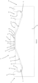
- Pad spring 20 includes a straight, intermediate portion 22 that defines a plane P.
- This portion 22 has a first end 24 and a second end 26, the ends being opposite to one another.
- the straight, intermediate portion 22 is 12mm long in the circumferential direction.
- the straight, intermediate portion is 14.5mm wide in the axial direction in this embodiment. In other embodiments the straight portion may be in a range of 5mm to 15mm long, for example.
- the pad spring 20 also includes a first arm 28 and a second arm 34.
- the first arm 28 has a free end 30 and an intermediate portion end 32.
- the free end 30 and intermediate portion end 32 are opposite one another.
- second arm 34 has a free end 36 and an opposite, intermediate portion end 38.
- the first arm 28 extends, without discontinuity, from the first end 24 of the intermediate portion 22.
- the first arm 28 extends from the first end 24 inclined out of the plane defined by the intermediate portion 22. That is, between the first end 24 of the intermediate portion 22 and the intermediate portion end 32 of arm 28 there is a single arcuate transition portion 25 whose centre of curvature is radially inward of the pad spring as installed. This arcuate transition portion forms a smooth transition from the intermediate portion 22 to the first arm 28.
- the second arm 34 extends without discontinuity from the second end 26 of the intermediate portion 22 in the same manner as the first.
- the second arm 34 extends inclined out of the plane defined by the intermediate portion 22 on the same side of the plane as the first arm 28.
- Both arms 28, 34 extend from the plane P defined by the straight, intermediate portion 22 at an angle in the range of 20° to 35° in a free (unfitted) condition In this embodiment the angle is approx. 31° in the free condition and 25°in the fitted condition.
- each arm 28, 34 curve in the opposite direction to the transition portion. That is the centres of curvature of the arms 28 and 34 are radially outward of the pad spring 20.
- a major portion of each arm has a shallow curvature - i.e. the radius of curvature is relatively large - in a range of 250mm to 400mm, approx. 325mm in this embodiment.
- the direction of curvature is back towards the plane P.
- each arm 28, 34 transition into a tighter curve having a radius of 4.5mm in this embodiment, but typically in a radius of 3mm to 10mm.
- the centre of curvature is also located radially outward of the pad spring 20 (i.e. each arm curves outwardly along its length, but the curve tightens at the free ends.
- the free ends curve, in this embodiment to the end that start to curve back towards the remainder of the arm.
- Each curved end 30, 36 describes an angle of approximately 230°, although smaller angles are possible as long as they are greater than (120°).
- Both arms 28, 34 are 55mm long in the circumferential direction. This is when measured in a flat condition before any forming or shaping takes place.
- the first arm 28 is formed over the majority of its length from two parallel elements 40, 42 to form an aperture 44 therebetween.
- the second arm 34 is formed from two mutually aligned, spaced, elements 46, 48 to form an aperture 50 therebetween.
- the apertures 44, 50 are obround in shape and lie in the centre of the width of the corresponding arm 28, 34.
- the apertures 44, 50 extend for the majority of the length of each arm and are around 5mm wide. In this embodiment each aperture at least reaches the intermediate portion 22 at a first end, at extend the complete length of the region of shallow curvature, terminating at the transition from the shallow curvature to the tighter curve at the free ends 30, 36.
- the pad spring 20 is symmetrical about the centre of the straight, intermediate portion 22, when viewed in the axial direction (as shown in Figure 1 ).
- the pad spring 20 may be asymmetrical about the centre of the straight, intermediate portion 22, when viewed in the axial direction.
- a symmetrical or asymmetrical pad spring 20 brings different benefits, which will be described in more detail below.
- the pad spring 20 is formed from 1.2mm thick material, but may typically be in a range from 1mm to 1.4mm thick material.
- the pad spring 20 is made from high carbon steel, typically which has been heat treated, although it can be made from any other suitable material.
- a suitable material is generally defined as one that is as light as possible, whilst having the mechanical properties to withstand the stress exerted upon the pad spring 20 in use, for an appropriate service life and lends itself to the manufacturing process.
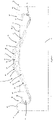
- Figure 8 shows the first and second aspects of the present teachings within a disc brake pad assembly 10 of a type utilised for heavy vehicles such as trucks, buses and coaches.
- the directions inboard I and outboard O refer to the typical orientation of the disc brake pad assembly 10 when fitted to a vehicle and with reference to a longitudinal centre line of the vehicle.
- the disc brake pad assembly 10 comprises a brake caliper 11 slidably mounted with respect to a brake carrier 12 by two guide assemblies (not shown).
- the caliper 20 has a housing 13 typically formed from cast iron or steel.
- the carrier 12 is typically also formed from cast iron or steel.
- the brake carrier 12 carries an inboard brake pad 14a and an outboard brake pad 14b.
- a rotor or disc (not shown) is rotatable about an axis extending in the axial direction, and is positioned between the brake pads 14a and 14b.
- An air actuator (not shown) is provided to move the inboard brake pad 14a into frictional contact with the rotor or disc via a suitable actuation mechanism (not shown) housed within the caliper housing 13 and which acts on the inboard brake pad 14a.
- a suitable actuation mechanism housed within the caliper housing 13 and which acts on the inboard brake pad 14a.
- the outboard brake pad 14b is formed of a backplate 15 of substantially rigid material, mounted to which is relatively brittle friction material 18.
- the inboard brake pad 14a is formed of a backplate 15, mounted to which is friction material 18.
- a spreader plate 16 is interposed between the inboard brake pad 14a and the actuation mechanism to distribute the load exerted on the inboard brake pad 14a by the actuation mechanism across a larger area of the backplate 15 for better wear characteristics.
- the backplates 15 are typically manufactured from stamped or cast steel that is 5-12mm thick.
- a pad retainer 17 is secured to the brake caliper 11. This pad retainer 17 applies a pre-load to the pad springs 20, which in turn are fitted to the backplates 15 and the spreader plate 16 of the disc brake pad assembly 10. Removal of the pad retainer 17 during maintenance operations allows the replacement or inspection of the brake pads 14a and/or 14b through a radial opening 19 in the brake caliper 11 without the need to dismount the brake caliper from the brake carrier 12. This is significant for heavy vehicle disc brakes, as the mass of the heavy vehicle calipers makes their dismounting an operation it is not safe for a single maintenance technician to perform alone.
- the pad springs 20 allows the backplates 15 and spreader plate 16 to slide towards the rotor on the brake carrier 12, whilst minimising rattling and impacts between the pads 14a, b and the carrier 12 or retainer 17 that may cause damage to the contact surfaces.
- the pad spring 20 is substantially similar to the one shown in Figures 1 to 4 . Parts corresponding to parts in Figures 1 to 4 carry the same reference numerals.
- Figure 5 shows a backplate 15 or spreader plate 16 and the pad retainer 17 of a disc brake pad spring assembly.
- the backplate 15 and spreader plate 16 contain a radially outward edge 54, a radially inward edge 55, a circumferentially leading edge 56 and a circumferentially trailing edge 58.
- the inward edge 55, leading 56 and trailing 58 edges are supported by corresponding surfaces of the brake carrier 12.
- the backplate 15 contains a friction material mounting surface 52.
- leading and “trailing” relate to the direction of rotation of the brake disc in forward travel of the vehicle, the leading edge being the edge encountered first by the brake disc in each rotation.
- the radially outward edge 54 has a depression 60, then a lobe 64.
- a depression 62 in the opposite direction, towards second end 56, there is a depression 62, then a lobe 66.
- Both depressions 60, 62 when travelling from the centre of the radially outward edge 54) have a corner 68, 70 acting as a projection to pass through apertures 44, 50 and an inner surface 72, 74.
- the backplate 15 and spreader plate 16 extend circumferentially beyond the dimensions shown in Figure 5 .
- the circumferential length of the backplates 15 and spreader plate 16 is more than twice that of the pad spring 20, in this embodiment.
- the relative lengths may be in a range of 1:3 to 1:1.9.
- the pad retainer 17 has a planar load surface 76. This surface 76 faces radially inward towards, and is parallel to, the radially outward edge 54 of backplate 15 and spreader plate 16 when assembled.
- Figures 6 and 7 show a central, radially outward portion of a pad spring assembly 51, in which the pad spring 20 of figs. 1 to 4 fits with the backplate 15 or spreader plate 16 (collectively referred to as a mounting plate) and pad retainer 17 of Figure 5 .
- the pad spring 20 fits with the backplate 15 and the spreader plate 16 such that the arms 28, 34 are inclined out of the plane defined by the intermediate portion 22 towards the friction surface 52.
- Figure 6 shows the pad spring 20 in a pre-loaded condition 78
- Figure 7 shows the pad spring 20 in the pre-loaded condition 78 (in broken lines) and a free condition 80 (in unbroken lines).
- the maximum travel the pad spring 20 is subjected to under normal use is when the straight, intermediate portion 22 contacts the radially outward edge 54 when fitted to the backplate 15 or spreader plate 16. This constitutes the maximum load on the pad spring 20.
- This may correspond to the backplate 15 or spreader plate 16 lifting off the carrier 12 as a result of travel over an uneven road surface, for example. In this embodiment the travel is approximately 0.6mm, but may vary between 0.4mm and 2mm in other embodiments.
- the pad spring 20 is fitted to the backplate 15 or spreader plate 16 such that the curvature of the free ends 30, 36 of the pad springs 20 are substantially concentric with the curvature of the inner surfaces 72, 74 of the depressions 60, 62 of the backplate 15 to spreader plate 16.
- the material of corners 68, 70 of the backplate 15 or spreader plate 16 passes through the apertures 44, 50 of the pad spring 20.
- a pre-load is exerted upon the pad spring 20 via the pad retainer 17, the load surface 76 of which is in contact with the radially outward surface of the straight intermediate portion 22 of pad spring 20.
- the concentric inner surfaces 72, 74 and free ends 30, 36 result in preferential contact surfaces that ideally distribute the stress throughout the arms 28, 34 which results in the stresses being reacted with a substantial resultant in the circumferential direction. This loads the arms 28, 34 more in compression and less in bending. This may result in an increased service life of the pad spring 20.
- the interaction between the inner surfaces 72, 74 and free ends 30, 36 also ensures there is no circumferential movement of the pad spring 20 in use.
- the lobes 64, 66 are shaped such that the curved, free ends 30, 36 of arms 28, 34 cannot move radially outward when the pad spring 20 is fitted.
- the straight intermediate portion 22 also ensures that the load applied by pad retainer 17 is absorbed by the pad spring 20 predominantly via compression of the arms 28, 34, resulting in additional bending of the major part of the arms (a reduction in their radius of curvature) rather than the bending of the intermediate portion 22. As such, the stresses in pad spring 20 are ideally distributed, whilst maintaining a large contact area between the pad retainer 17 and the intermediate portion.
- the material of rounded corners 68, 70 passing through apertures 44, 50 restricts movement of the pad spring 20 in the axial direction and further minimise rattling when in use.
- the pad spring 20 is symmetrical about the centre of the straight, intermediate portion 22 when viewed in the axial direction. This is more suited to a situation in which the packaging restraints prefer a symmetrical design, or the forces acting upon the disc brake pad assembly 10 in the circumferential direction are roughly equal. In other embodiments, the pad spring 20 is asymmetrical about the centre of the straight, intermediate portion 22 when viewed in the axial direction. This may be the case if one or both of the brake pads are circumferentially offset from the carrier centreline of action of the actuation mechanism.
Landscapes
- Engineering & Computer Science (AREA)
- General Engineering & Computer Science (AREA)
- Mechanical Engineering (AREA)
- Transportation (AREA)
- Braking Arrangements (AREA)
Claims (15)
- Ressort de plaquette (20) pour un ensemble à plaquette de frein (10), le ressort de plaquette (20) ayantune partie intermédiaire droite (22) ayant des première (24) et seconde (26) extrémités opposées et définissant un plan (P),un premier bras (28) s'étendant, sans discontinuité, depuis la première extrémité (24) de la partie intermédiaire (22), incliné hors du plan (P) etun second bras (34) s'étendant, sans discontinuité, depuis la seconde extrémité (26) de la partie intermédiaire (22), incliné hors du plan (P) sur le même côté du plan (P) que le premier bras (28), chaque bras (28, 34) ayantune extrémité de partie intermédiaire (32, 38) et une extrémité libre opposée (30, 36), l'extrémité libre (30, 36) de chaque bras (28, 34) s'incurvant vers l'extérieur relativement à la partie intermédiaire (22) et de retour vers le plan (P), chaque extrémité incurvée (30, 36) décrivant un angle d'au moins 120°.
- Ressort de plaquette (20) selon la revendication 1, dans lequel au moins un des bras (28, 34) a une partie principale ayant une forme arquée, de préférence d'un rayon de 250 mm à 400 mm.
- Ressort de plaquette (20) selon la revendication 2, dans lequel au moins un des bras de forme arquée (28, 34) a un centre de courbure radialement à l'extérieur du ressort (20).
- Ressort de plaquette (20) selon l'une quelconque des revendications 1 à 3, dans lequel le ressort (20) est formé de matériau ayant une épaisseur inférieure à 1,6 mm, de préférence de 0,8 mm à 1,4 mm, par exemple de 1,2 mm.
- Ressort de plaquette (20) selon l'une quelconque des revendications 1 à 4, dans lequel au moins un des bras (28, 34) est formé de deux éléments espacés parallèles (40, 42, 46, 48) pour former une ouverture (44, 50) entre ceux-ci, de préférence dans lequel l'ouverture (44, 50) s'étend jusqu'à la partie intermédiaire droite (22).
- Ressort de plaquette (20) selon l'une quelconque des revendications 1 à 5, dans lequel au moins un des bras (28, 34) s'étend à un angle de 20° à 40° depuis la partie intermédiaire droite (22), optionnellement dans lequel ledit angle est c.25°, optionnellement dans lequel l'angle selon lequel chaque bras (28, 34) s'étend relativement au plan (P) est le même.
- Ressort de plaquette (20) selon l'une quelconque des revendications 1 à 6, dans lequel au moins une extrémité incurvée (30, 36) décrit un angle d'au moins 180°.
- Ressort de plaquette (20) selon l'une quelconque des revendications 1 à 7, dans lequel la partie intermédiaire droite (22) fait de 5 à 15 mm de long dans la direction tangentielle et/ou fait de 10 mm à 20 mm de large dans la direction axiale.
- Ressort de plaquette (20) selon l'une quelconque des revendications 1 à 8, dans lequel au moins un des bras (28, 34) fait de 45 mm à 50 mm de long dans la direction circonférentielle, mesuré lorsqu'il est dans une condition plate avant formage.
- Ressort de plaquette (20) selon l'une quelconque des revendications 1 à 9, dans lequel le ressort (20) est symétrique autour du centre de la partie intermédiaire droite (22) en vue dans la direction axiale.
- Ressort de plaquette (20) selon l'une quelconque des revendications 1 à 10, dans lequel le ressort (20) est fait de métal, optionnellement d'acier à haute teneur en carbone.
- Ensemble à ressort de plaquette de frein à disque (10), l'ensemble (10) ayant un ressort de plaquette (20) selon l'une quelconque des revendications 1 à 11 et une plaque de montage (15, 16), la plaque de montage (15, 16) ayant des butées espacées opposées (64, 66) définissant des creux de butée (60, 62), les extrémités libres (30, 36) des bras de ressort de plaquette (28, 34) s'ajustant dans les creux de butée (60, 62) de manière circonférentiellement restreinte, de telle sorte que l'application d'une charge sur le ressort de plaquette (20) au niveau de la partie intermédiaire droite (22) ait pour résultat le fait qu'une réaction à des contraintes soit produite, avec une résultante importante dans la direction circonférentielle.
- Ensemble à ressort de plaquette de frein à disque (10) selon la revendication 12, dans lequel le rapport des longueurs circonférentielles du ressort de plaquette (20) et de la plaque de support (15) est de 1 : 3 à 1 : 1,9, optionnellement de 1 : 2,7 à 1 : 2.
- Ensemble à plaquette de frein à disque (10), contenant un ressort (20) selon l'une quelconque des revendications 1 à 11.
- Frein à disque de véhicule lourd, comprenant un ensemble à plaquette de frein à disque (10) selon la revendication 14.
Priority Applications (4)
| Application Number | Priority Date | Filing Date | Title |
|---|---|---|---|
| EP23160278.0A EP4212756A1 (fr) | 2020-01-08 | 2020-01-08 | Ressort de plaquette de frein a disque |
| EP20150815.7A EP3848604B1 (fr) | 2020-01-08 | 2020-01-08 | Ressort de plaquette de frein à disque |
| US17/129,409 US11655866B2 (en) | 2020-01-08 | 2020-12-21 | Disc brake pad spring |
| CN202011554280.2A CN113090687B (zh) | 2020-01-08 | 2020-12-24 | 盘式制动衬块弹簧 |
Applications Claiming Priority (1)
| Application Number | Priority Date | Filing Date | Title |
|---|---|---|---|
| EP20150815.7A EP3848604B1 (fr) | 2020-01-08 | 2020-01-08 | Ressort de plaquette de frein à disque |
Related Child Applications (1)
| Application Number | Title | Priority Date | Filing Date |
|---|---|---|---|
| EP23160278.0A Division EP4212756A1 (fr) | 2020-01-08 | 2020-01-08 | Ressort de plaquette de frein a disque |
Publications (2)
| Publication Number | Publication Date |
|---|---|
| EP3848604A1 EP3848604A1 (fr) | 2021-07-14 |
| EP3848604B1 true EP3848604B1 (fr) | 2023-03-08 |
Family
ID=69156236
Family Applications (2)
| Application Number | Title | Priority Date | Filing Date |
|---|---|---|---|
| EP23160278.0A Pending EP4212756A1 (fr) | 2020-01-08 | 2020-01-08 | Ressort de plaquette de frein a disque |
| EP20150815.7A Active EP3848604B1 (fr) | 2020-01-08 | 2020-01-08 | Ressort de plaquette de frein à disque |
Family Applications Before (1)
| Application Number | Title | Priority Date | Filing Date |
|---|---|---|---|
| EP23160278.0A Pending EP4212756A1 (fr) | 2020-01-08 | 2020-01-08 | Ressort de plaquette de frein a disque |
Country Status (3)
| Country | Link |
|---|---|
| US (1) | US11655866B2 (fr) |
| EP (2) | EP4212756A1 (fr) |
| CN (1) | CN113090687B (fr) |
Citations (6)
| Publication number | Priority date | Publication date | Assignee | Title |
|---|---|---|---|---|
| JPH0669461U (ja) | 1993-03-15 | 1994-09-30 | トキコ株式会社 | ディスクブレーキ |
| EP0752541A1 (fr) | 1995-07-05 | 1997-01-08 | LUCAS INDUSTRIES public limited company | Frein à disque |
| US20030010582A1 (en) | 2001-07-11 | 2003-01-16 | Federal-Mogul Friction Products Gmbh | Disk brake with integrated brake lining |
| JP2005291331A (ja) | 2004-03-31 | 2005-10-20 | Nissin Kogyo Co Ltd | 車両用ディスクブレーキ |
| DE102005052435A1 (de) | 2005-11-03 | 2007-05-10 | Knorr-Bremse Systeme für Nutzfahrzeuge GmbH | Bremsbelaghalterung und Bremsbelag für eine Scheibenbremse |
| DE102005052434A1 (de) | 2005-11-03 | 2007-05-16 | Knorr Bremse Systeme | Scheibenbremse, insbesondere für ein Nutzfahrzeug, sowie Bremsbelag für eine Scheibenbremse |
Family Cites Families (11)
| Publication number | Priority date | Publication date | Assignee | Title |
|---|---|---|---|---|
| US3625316A (en) | 1969-02-21 | 1971-12-07 | Aisin Seiki | Antirattling device of disc brake |
| DE9010012U1 (de) * | 1990-07-02 | 1991-10-31 | Lucas Industries P.L.C., Birmingham, West Midlands | Bremsbacke für Teilbelag-Scheibenbremsen |
| DE4426603A1 (de) | 1994-07-27 | 1996-02-01 | Perrot Bremsen Gmbh | Vorrichtung zum Halten eines Bremsbelages in einer Scheibenbremse |
| DE69429346T2 (de) * | 1994-09-22 | 2002-08-22 | Meritor Heavy Vehicle Technology, Llc | Scheibenbremsbelag und Haltesystem |
| DE69925848D1 (de) * | 1999-12-16 | 2005-07-21 | Freni Brembo Spa | Befestigungsklammer für Bremsbelagshaltestifte |
| ES2334679T3 (es) * | 2005-03-04 | 2010-03-15 | Emmerre S.R.L. | Dispositivo de fijacion para pastillas de disco. |
| US8215458B2 (en) * | 2008-11-07 | 2012-07-10 | Knorr-Bremse Systeme Fuer Nutzfahrzeuge Gmbh | Fixedly connected pad retaining spring for a brake pad |
| GB201211722D0 (en) | 2012-07-02 | 2012-08-15 | Meritor Heavy Vehicle Braking | A disc brake |
| JP6261289B2 (ja) | 2013-11-07 | 2018-01-17 | 曙ブレーキ工業株式会社 | ディスクブレーキ用パッドスプリング |
| AU2017225663B2 (en) * | 2016-03-03 | 2021-09-23 | Bendix Spicer Foundation Brake Llc | Disc brake and brake pad set |
| GB2566335A (en) * | 2017-09-12 | 2019-03-13 | Meritor Heavy Vehicle Braking Systems Uk Ltd | A disc brake |
-
2020
- 2020-01-08 EP EP23160278.0A patent/EP4212756A1/fr active Pending
- 2020-01-08 EP EP20150815.7A patent/EP3848604B1/fr active Active
- 2020-12-21 US US17/129,409 patent/US11655866B2/en active Active
- 2020-12-24 CN CN202011554280.2A patent/CN113090687B/zh active Active
Patent Citations (6)
| Publication number | Priority date | Publication date | Assignee | Title |
|---|---|---|---|---|
| JPH0669461U (ja) | 1993-03-15 | 1994-09-30 | トキコ株式会社 | ディスクブレーキ |
| EP0752541A1 (fr) | 1995-07-05 | 1997-01-08 | LUCAS INDUSTRIES public limited company | Frein à disque |
| US20030010582A1 (en) | 2001-07-11 | 2003-01-16 | Federal-Mogul Friction Products Gmbh | Disk brake with integrated brake lining |
| JP2005291331A (ja) | 2004-03-31 | 2005-10-20 | Nissin Kogyo Co Ltd | 車両用ディスクブレーキ |
| DE102005052435A1 (de) | 2005-11-03 | 2007-05-10 | Knorr-Bremse Systeme für Nutzfahrzeuge GmbH | Bremsbelaghalterung und Bremsbelag für eine Scheibenbremse |
| DE102005052434A1 (de) | 2005-11-03 | 2007-05-16 | Knorr Bremse Systeme | Scheibenbremse, insbesondere für ein Nutzfahrzeug, sowie Bremsbelag für eine Scheibenbremse |
Also Published As
| Publication number | Publication date |
|---|---|
| CN113090687B (zh) | 2023-09-15 |
| CN113090687A (zh) | 2021-07-09 |
| EP3848604A1 (fr) | 2021-07-14 |
| EP4212756A1 (fr) | 2023-07-19 |
| US20210207669A1 (en) | 2021-07-08 |
| US11655866B2 (en) | 2023-05-23 |
Similar Documents
| Publication | Publication Date | Title |
|---|---|---|
| US10563713B2 (en) | Disc brake for a commercial vehicle and brake pad set | |
| US9285002B2 (en) | Disk brake of a motor vehicle and brake pad | |
| US20050284710A1 (en) | Brake assembly | |
| JP4698147B2 (ja) | ディスクブレーキ組立体 | |
| CN108138877B (zh) | 磨损优化的片设计 | |
| US10781875B2 (en) | Disc brake | |
| EP3848604B1 (fr) | Ressort de plaquette de frein à disque | |
| US20180347648A1 (en) | Brake pad | |
| JP4942865B2 (ja) | ディスクブレーキ装置及びそのための帯状弾性装置 | |
| EP1984643B1 (fr) | Ressort pour retenir des coussins dans un etrier de frein a disque | |
| US9976610B2 (en) | Wear optimized pad design | |
| EP4107405B1 (fr) | Système de retenue de patin de frein, patin de frein et véhicule | |
| US10724585B2 (en) | Brake pad | |
| US20070256900A1 (en) | Disk Brake | |
| EP4105510B1 (fr) | Frein à disque à air pour véhicule routier | |
| CN108980237B (zh) | 盘式制动器 | |
| US12078216B2 (en) | Disc brake | |
| US20180347653A1 (en) | Brake pad | |
| EP3450791A1 (fr) | Élément de friction | |
| CN117795224A (zh) | 用于商用车的盘式制动器以及用于盘式制动器的制动衬片 | |
| JP2012127363A (ja) | ドラムインディスクブレーキ |
Legal Events
| Date | Code | Title | Description |
|---|---|---|---|
| PUAI | Public reference made under article 153(3) epc to a published international application that has entered the european phase |
Free format text: ORIGINAL CODE: 0009012 |
|
| STAA | Information on the status of an ep patent application or granted ep patent |
Free format text: STATUS: THE APPLICATION HAS BEEN PUBLISHED |
|
| AK | Designated contracting states |
Kind code of ref document: A1 Designated state(s): AL AT BE BG CH CY CZ DE DK EE ES FI FR GB GR HR HU IE IS IT LI LT LU LV MC MK MT NL NO PL PT RO RS SE SI SK SM TR |
|
| STAA | Information on the status of an ep patent application or granted ep patent |
Free format text: STATUS: REQUEST FOR EXAMINATION WAS MADE |
|
| 17P | Request for examination filed |
Effective date: 20220111 |
|
| RBV | Designated contracting states (corrected) |
Designated state(s): AL AT BE BG CH CY CZ DE DK EE ES FI FR GB GR HR HU IE IS IT LI LT LU LV MC MK MT NL NO PL PT RO RS SE SI SK SM TR |
|
| GRAP | Despatch of communication of intention to grant a patent |
Free format text: ORIGINAL CODE: EPIDOSNIGR1 |
|
| STAA | Information on the status of an ep patent application or granted ep patent |
Free format text: STATUS: GRANT OF PATENT IS INTENDED |
|
| INTG | Intention to grant announced |
Effective date: 20220509 |
|
| GRAJ | Information related to disapproval of communication of intention to grant by the applicant or resumption of examination proceedings by the epo deleted |
Free format text: ORIGINAL CODE: EPIDOSDIGR1 |
|
| STAA | Information on the status of an ep patent application or granted ep patent |
Free format text: STATUS: REQUEST FOR EXAMINATION WAS MADE |
|
| INTC | Intention to grant announced (deleted) | ||
| GRAP | Despatch of communication of intention to grant a patent |
Free format text: ORIGINAL CODE: EPIDOSNIGR1 |
|
| STAA | Information on the status of an ep patent application or granted ep patent |
Free format text: STATUS: GRANT OF PATENT IS INTENDED |
|
| INTG | Intention to grant announced |
Effective date: 20221007 |
|
| GRAS | Grant fee paid |
Free format text: ORIGINAL CODE: EPIDOSNIGR3 |
|
| GRAA | (expected) grant |
Free format text: ORIGINAL CODE: 0009210 |
|
| STAA | Information on the status of an ep patent application or granted ep patent |
Free format text: STATUS: THE PATENT HAS BEEN GRANTED |
|
| AK | Designated contracting states |
Kind code of ref document: B1 Designated state(s): AL AT BE BG CH CY CZ DE DK EE ES FI FR GB GR HR HU IE IS IT LI LT LU LV MC MK MT NL NO PL PT RO RS SE SI SK SM TR |
|
| REG | Reference to a national code |
Ref country code: CH Ref legal event code: EP Ref country code: AT Ref legal event code: REF Ref document number: 1552747 Country of ref document: AT Kind code of ref document: T Effective date: 20230315 |
|
| REG | Reference to a national code |
Ref country code: IE Ref legal event code: FG4D |
|
| REG | Reference to a national code |
Ref country code: DE Ref legal event code: R096 Ref document number: 602020008591 Country of ref document: DE |
|
| REG | Reference to a national code |
Ref country code: NL Ref legal event code: FP |
|
| REG | Reference to a national code |
Ref country code: SE Ref legal event code: TRGR |
|
| REG | Reference to a national code |
Ref country code: LT Ref legal event code: MG9D |
|
| P01 | Opt-out of the competence of the unified patent court (upc) registered |
Effective date: 20230531 |
|
| PG25 | Lapsed in a contracting state [announced via postgrant information from national office to epo] |
Ref country code: RS Free format text: LAPSE BECAUSE OF FAILURE TO SUBMIT A TRANSLATION OF THE DESCRIPTION OR TO PAY THE FEE WITHIN THE PRESCRIBED TIME-LIMIT Effective date: 20230308 Ref country code: NO Free format text: LAPSE BECAUSE OF FAILURE TO SUBMIT A TRANSLATION OF THE DESCRIPTION OR TO PAY THE FEE WITHIN THE PRESCRIBED TIME-LIMIT Effective date: 20230608 Ref country code: LV Free format text: LAPSE BECAUSE OF FAILURE TO SUBMIT A TRANSLATION OF THE DESCRIPTION OR TO PAY THE FEE WITHIN THE PRESCRIBED TIME-LIMIT Effective date: 20230308 Ref country code: LT Free format text: LAPSE BECAUSE OF FAILURE TO SUBMIT A TRANSLATION OF THE DESCRIPTION OR TO PAY THE FEE WITHIN THE PRESCRIBED TIME-LIMIT Effective date: 20230308 Ref country code: HR Free format text: LAPSE BECAUSE OF FAILURE TO SUBMIT A TRANSLATION OF THE DESCRIPTION OR TO PAY THE FEE WITHIN THE PRESCRIBED TIME-LIMIT Effective date: 20230308 Ref country code: ES Free format text: LAPSE BECAUSE OF FAILURE TO SUBMIT A TRANSLATION OF THE DESCRIPTION OR TO PAY THE FEE WITHIN THE PRESCRIBED TIME-LIMIT Effective date: 20230308 |
|
| REG | Reference to a national code |
Ref country code: AT Ref legal event code: MK05 Ref document number: 1552747 Country of ref document: AT Kind code of ref document: T Effective date: 20230308 |
|
| PG25 | Lapsed in a contracting state [announced via postgrant information from national office to epo] |
Ref country code: GR Free format text: LAPSE BECAUSE OF FAILURE TO SUBMIT A TRANSLATION OF THE DESCRIPTION OR TO PAY THE FEE WITHIN THE PRESCRIBED TIME-LIMIT Effective date: 20230609 Ref country code: FI Free format text: LAPSE BECAUSE OF FAILURE TO SUBMIT A TRANSLATION OF THE DESCRIPTION OR TO PAY THE FEE WITHIN THE PRESCRIBED TIME-LIMIT Effective date: 20230308 |
|
| PG25 | Lapsed in a contracting state [announced via postgrant information from national office to epo] |
Ref country code: SM Free format text: LAPSE BECAUSE OF FAILURE TO SUBMIT A TRANSLATION OF THE DESCRIPTION OR TO PAY THE FEE WITHIN THE PRESCRIBED TIME-LIMIT Effective date: 20230308 Ref country code: RO Free format text: LAPSE BECAUSE OF FAILURE TO SUBMIT A TRANSLATION OF THE DESCRIPTION OR TO PAY THE FEE WITHIN THE PRESCRIBED TIME-LIMIT Effective date: 20230308 Ref country code: PT Free format text: LAPSE BECAUSE OF FAILURE TO SUBMIT A TRANSLATION OF THE DESCRIPTION OR TO PAY THE FEE WITHIN THE PRESCRIBED TIME-LIMIT Effective date: 20230710 Ref country code: EE Free format text: LAPSE BECAUSE OF FAILURE TO SUBMIT A TRANSLATION OF THE DESCRIPTION OR TO PAY THE FEE WITHIN THE PRESCRIBED TIME-LIMIT Effective date: 20230308 Ref country code: CZ Free format text: LAPSE BECAUSE OF FAILURE TO SUBMIT A TRANSLATION OF THE DESCRIPTION OR TO PAY THE FEE WITHIN THE PRESCRIBED TIME-LIMIT Effective date: 20230308 Ref country code: AT Free format text: LAPSE BECAUSE OF FAILURE TO SUBMIT A TRANSLATION OF THE DESCRIPTION OR TO PAY THE FEE WITHIN THE PRESCRIBED TIME-LIMIT Effective date: 20230308 |
|
| PG25 | Lapsed in a contracting state [announced via postgrant information from national office to epo] |
Ref country code: SK Free format text: LAPSE BECAUSE OF FAILURE TO SUBMIT A TRANSLATION OF THE DESCRIPTION OR TO PAY THE FEE WITHIN THE PRESCRIBED TIME-LIMIT Effective date: 20230308 Ref country code: PL Free format text: LAPSE BECAUSE OF FAILURE TO SUBMIT A TRANSLATION OF THE DESCRIPTION OR TO PAY THE FEE WITHIN THE PRESCRIBED TIME-LIMIT Effective date: 20230308 Ref country code: IS Free format text: LAPSE BECAUSE OF FAILURE TO SUBMIT A TRANSLATION OF THE DESCRIPTION OR TO PAY THE FEE WITHIN THE PRESCRIBED TIME-LIMIT Effective date: 20230708 |
|
| REG | Reference to a national code |
Ref country code: DE Ref legal event code: R026 Ref document number: 602020008591 Country of ref document: DE |
|
| PLBI | Opposition filed |
Free format text: ORIGINAL CODE: 0009260 |
|
| PLAX | Notice of opposition and request to file observation + time limit sent |
Free format text: ORIGINAL CODE: EPIDOSNOBS2 |
|
| 26 | Opposition filed |
Opponent name: VRI-PATENT MONITORING ASSOCIATION Effective date: 20231208 |
|
| PG25 | Lapsed in a contracting state [announced via postgrant information from national office to epo] |
Ref country code: SI Free format text: LAPSE BECAUSE OF FAILURE TO SUBMIT A TRANSLATION OF THE DESCRIPTION OR TO PAY THE FEE WITHIN THE PRESCRIBED TIME-LIMIT Effective date: 20230308 Ref country code: DK Free format text: LAPSE BECAUSE OF FAILURE TO SUBMIT A TRANSLATION OF THE DESCRIPTION OR TO PAY THE FEE WITHIN THE PRESCRIBED TIME-LIMIT Effective date: 20230308 |
|
| PGFP | Annual fee paid to national office [announced via postgrant information from national office to epo] |
Ref country code: NL Payment date: 20240126 Year of fee payment: 5 |
|
| PLBB | Reply of patent proprietor to notice(s) of opposition received |
Free format text: ORIGINAL CODE: EPIDOSNOBS3 |
|
| PGFP | Annual fee paid to national office [announced via postgrant information from national office to epo] |
Ref country code: DE Payment date: 20240129 Year of fee payment: 5 Ref country code: GB Payment date: 20240129 Year of fee payment: 5 |
|
| PG25 | Lapsed in a contracting state [announced via postgrant information from national office to epo] |
Ref country code: IT Free format text: LAPSE BECAUSE OF FAILURE TO SUBMIT A TRANSLATION OF THE DESCRIPTION OR TO PAY THE FEE WITHIN THE PRESCRIBED TIME-LIMIT Effective date: 20230308 |
|
| PGFP | Annual fee paid to national office [announced via postgrant information from national office to epo] |
Ref country code: SE Payment date: 20240127 Year of fee payment: 5 Ref country code: FR Payment date: 20240125 Year of fee payment: 5 |
|
| PG25 | Lapsed in a contracting state [announced via postgrant information from national office to epo] |
Ref country code: MC Free format text: LAPSE BECAUSE OF FAILURE TO SUBMIT A TRANSLATION OF THE DESCRIPTION OR TO PAY THE FEE WITHIN THE PRESCRIBED TIME-LIMIT Effective date: 20230308 |
|
| PG25 | Lapsed in a contracting state [announced via postgrant information from national office to epo] |
Ref country code: MC Free format text: LAPSE BECAUSE OF FAILURE TO SUBMIT A TRANSLATION OF THE DESCRIPTION OR TO PAY THE FEE WITHIN THE PRESCRIBED TIME-LIMIT Effective date: 20230308 |
|
| REG | Reference to a national code |
Ref country code: CH Ref legal event code: PL |
|
| PG25 | Lapsed in a contracting state [announced via postgrant information from national office to epo] |
Ref country code: LU Free format text: LAPSE BECAUSE OF NON-PAYMENT OF DUE FEES Effective date: 20240108 |