EP3848540A1 - A striker plate for a lock assembly, said lock assembly, and a window comprising said lock assembly - Google Patents
A striker plate for a lock assembly, said lock assembly, and a window comprising said lock assembly Download PDFInfo
- Publication number
- EP3848540A1 EP3848540A1 EP21150853.6A EP21150853A EP3848540A1 EP 3848540 A1 EP3848540 A1 EP 3848540A1 EP 21150853 A EP21150853 A EP 21150853A EP 3848540 A1 EP3848540 A1 EP 3848540A1
- Authority
- EP
- European Patent Office
- Prior art keywords
- window
- striker plate
- locking pawl
- abutment element
- base
- Prior art date
- Legal status (The legal status is an assumption and is not a legal conclusion. Google has not performed a legal analysis and makes no representation as to the accuracy of the status listed.)
- Granted
Links
- 230000002787 reinforcement Effects 0.000 claims abstract description 31
- 230000002093 peripheral effect Effects 0.000 claims description 38
- 239000004033 plastic Substances 0.000 claims description 4
- 238000009423 ventilation Methods 0.000 description 8
- 239000000463 material Substances 0.000 description 4
- 239000004952 Polyamide Substances 0.000 description 2
- 239000004743 Polypropylene Substances 0.000 description 2
- 230000001154 acute effect Effects 0.000 description 2
- 230000000712 assembly Effects 0.000 description 2
- 238000000429 assembly Methods 0.000 description 2
- 230000001419 dependent effect Effects 0.000 description 2
- 239000000835 fiber Substances 0.000 description 2
- 229920002647 polyamide Polymers 0.000 description 2
- -1 polypropylene Polymers 0.000 description 2
- 229920001155 polypropylene Polymers 0.000 description 2
- 241001074085 Scophthalmus aquosus Species 0.000 description 1
- 229910000831 Steel Inorganic materials 0.000 description 1
- 238000013459 approach Methods 0.000 description 1
- 238000005452 bending Methods 0.000 description 1
- 238000004590 computer program Methods 0.000 description 1
- 238000009863 impact test Methods 0.000 description 1
- 230000003993 interaction Effects 0.000 description 1
- 238000004519 manufacturing process Methods 0.000 description 1
- 239000002184 metal Substances 0.000 description 1
- 230000003287 optical effect Effects 0.000 description 1
- 239000010959 steel Substances 0.000 description 1
Images


Classifications
-
- E—FIXED CONSTRUCTIONS
- E05—LOCKS; KEYS; WINDOW OR DOOR FITTINGS; SAFES
- E05B—LOCKS; ACCESSORIES THEREFOR; HANDCUFFS
- E05B15/00—Other details of locks; Parts for engagement by bolts of fastening devices
- E05B15/02—Striking-plates; Keepers; Bolt staples; Escutcheons
- E05B15/0205—Striking-plates, keepers, staples
-
- E—FIXED CONSTRUCTIONS
- E05—LOCKS; KEYS; WINDOW OR DOOR FITTINGS; SAFES
- E05C—BOLTS OR FASTENING DEVICES FOR WINGS, SPECIALLY FOR DOORS OR WINDOWS
- E05C3/00—Fastening devices with bolts moving pivotally or rotatively
- E05C3/02—Fastening devices with bolts moving pivotally or rotatively without latching action
- E05C3/06—Fastening devices with bolts moving pivotally or rotatively without latching action with operating handle or equivalent member moving otherwise than rigidly with the bolt
- E05C3/08—Fastening devices with bolts moving pivotally or rotatively without latching action with operating handle or equivalent member moving otherwise than rigidly with the bolt the handle or member moving essentially towards or away from the plane of the wing or frame
-
- E—FIXED CONSTRUCTIONS
- E05—LOCKS; KEYS; WINDOW OR DOOR FITTINGS; SAFES
- E05B—LOCKS; ACCESSORIES THEREFOR; HANDCUFFS
- E05B47/00—Operating or controlling locks or other fastening devices by electric or magnetic means
- E05B47/0001—Operating or controlling locks or other fastening devices by electric or magnetic means with electric actuators; Constructional features thereof
Definitions
- the disclosure relates to a striker plate, a lock assembly for locking a pivotable window sash to a window frame comprising such a striker plate, and a window comprising the lock assembly.
- Windows have to be burglarproof to the highest possible extent, without increasing the cost of the window and its locks to an unacceptable level. Furthermore, windows have to be as safe as possible also when opening is attempted unintentionally from the inside of a building, e.g. if a person falls onto the window sash. Window safety requirements are becoming more and more strict, for example current roof windows must withstand a 50 kg impact test, a requirement which is directed preventing an adult from falling through the window.
- Prior art solutions comprise lock assemblies having walls and locking pawls engaging each other when locked, and effectively counteracting any forces applied onto the window when the window is locked.
- EP 2,826,934 A2 and WO 2010/027288 A1 disclose two-part solutions which comprise a striker plate reinforced by a separate element lodged between the window frame and the striker plate. A single-part solution is shown in EP 2,607,578 .
- the capacity of resisting a large impact force, such as that caused by a heavy object hitting the window with considerable speed, is nevertheless preferably improved even further.
- a striker plate for interlocking engagement with at least one locking pawl, the striker plate comprising a base having a main surface delimited by at least a first peripheral edge and a second peripheral edge, and at least one abutment element protruding from the main surface in a first direction, the abutment element comprising a first face defining an abutment area configured to engage the locking pawl, and a reinforcement arrangement, the reinforcement arrangement protruding from a second face of the abutment element or being integrated with the abutment element and at least partially forming the second face of the abutment element.
- Such a striker plate provides an improved distribution and increase of the counteracting forces arising when a locked window is subject to opening attempts without opening the lock arrangement of the window, i.e., trying to force the window open when the striker plate and the locking pawl of the lock assembly are in a locked position. This reduces the risk of a locked window from being opened, regardless of whether the opening attempt is intentional, such as a burglar attempt from the exterior, or unintentional, such as an accidental fall towards the window from the interior.
- the main surface is substantially planar.
- first peripheral edge and the second peripheral edge extend along opposite sides of the main surface.
- the abutment element forms a wall.
- the striker plate is a single-piece element, simplifying manufacture, assembly, and fitting of the striker plate.
- the base comprises a first part and a second part, the first part comprising the first peripheral edge and the second part comprising the second peripheral edge, the abutment element protruding at least partially from the first part of the base.
- the first face of the abutment element faces towards the second part of the base and/or the second face of the abutment element faces away from the second part of the base.
- the striker plate comprises a plurality of throughgoing openings, each opening being configured to receive a fastener configured to attach the striker plate to a window sash or a window frame, facilitating a simple and reliable attachment solution for the striker plate, which also allows the striker plate to be retrofitted to existing windows.
- the striker plate comprises four to six throughgoing openings, facilitating an even more secure attachment of the striker plate to a window sash or window frame.
- the reinforcement arrangement comprises one of the throughgoing openings, the throughgoing opening and the fastener extending in a second direction as seen from the main surface, allowing the striker plate to be fitted, just as reliably, to a window frame having a relatively thin cross-section, such as, e.g., the window frame of a top-hung window.
- the second direction extends at an angle ⁇ 90° to the first direction.
- the throughgoing opening and the fastener extends at an acute angle to the abutment element.
- the second part of the base comprises a deformation section, preferably extending adjacent at least one of the throughgoing openings, the deformation section being configured to allow the base to undergo plastic deformation when there is an increase in force applied by the locking pawl onto the abutment area of the abutment element.
- the striker plate further comprises a guiding wall, the guiding wall protruding from an area of the main surface of the base located between the second peripheral edge and the abutment element, the guiding wall comprising a guide surface facing towards the abutment element, a slot being formed between the guide surface and the abutment element, the slot being configured for receiving the locking pawl, providing a slideway which is easily entered and exited by the locking pawl during intentional engagement and disengagement between slot and locking pawl.
- the striker plate comprises at least one of polypropylene and polyamide material.
- a lock assembly for locking a window sash to a window frame, the lock assembly comprising at least one moveable locking pawl and a striker plate according to the above, the locking pawl being moveable between an unlocked position and a locked position, each locking pawl engaging the abutment area of one abutment element of the striker plate when in the locked position.
- This lock assembly provides an improved distribution and increase of the counteracting forces arising when a locked window is subject to opening attempts without opening the lock arrangement of the window, i.e., trying to force the window open when the striker plate and the locking pawl are in a locked position.
- the lock assembly comprises a first locking pawl configured to engage a first abutment element and a second locking pawl configured to engage a second abutment element, the first locking pawl and the second locking pawl being configured to pivot simultaneously, and in opposite directions, when moving between the unlocked position and the locked position.
- the striker plate is configured for attachment to the window frame
- the locking pawl is configured for attachment to the window sash
- the striker plate being attached to the window frame such that the first part of the base faces the window frame, and the second part of the base faces the window sash.
- the striker plate is configured such that the reinforcement arrangement of the striker plate abuts against the window frame, allowing the rigidity of the window frame to contribute to an increase in the forces preventing a locked window sash from opening.
- the locking pawl is operatively connected to a lock mechanism, the lock mechanism being configured to pivot the locking pawl between the locked position and the unlocked position.
- a window comprising a window sash and a window frame adapted for receiving the window sash, the window further comprising the lock assembly according to the above, the window sash being locked to the window frame by means of the lock assembly.
- the window sash is configured to pivot around a pivot axis so as to open the window sash at least partially towards an interior of a structure comprising the window.
- a first end of the locking pawl of the lock assembly is pivotally connected to the window sash, and a second end of the locking pawl is bent to form a pawl member extending at an angle to the rest of the locking pawl, the pawl member being configured to engage with the abutment area of one abutment element of the striker plate, allowing simple operation during intentional engagement and disengagement between slot and locking pawl.
- the lock mechanism of the lock assembly comprises a manually operable handle, facilitating a simple solution in which both the lock assembly and the window can be opened and locked by means of one manipulation.
- the window further comprises a ventilation flap pivotally connected to the window sash, the handle being operatively connected to the ventilation flap for controlling the lock assembly as well as the ventilation flap, allowing yet another function to be operated by means of the above-mentioned manipulation.
- the window further comprises an electric actuator configured to operate the lock assembly, allowing the window to be operated automatically or manually be means of remote control.
- the base and the reinforcement arrangement of the striker plate of the lock assembly are configured to be mounted in abutment with the window frame, a force applied onto the window sash in a window opening direction generating a counterforce when the locking pawl is the locked position, preventing the window sash from opening, the counterforce being generated by means of the locking pawl engaging the locking wall and the reinforcement arrangement abutting the window frame, allowing the rigidity of the window frame to contribute to an increase in counteracting forces, effectively preventing a locked window from opening regardless of whether the opening attempt is intentional, such as a burglar attempt from the exterior, or unintentional, such as an accidental fall towards the window from the interior.
- the striker plate is attached to the window frame by means of a plurality of fasteners extending through the plurality of openings of the reinforcement arrangement of the striker plate, facilitating a simple and reliable fastening solution which also allows the striker plate to be retrofitted to existing windows.
- the first peripheral edge of the base of the lock assembly is configured to abut against a first surface of the window frame
- the reinforcement arrangement is configured to abut against a second surface of the window frame, the first surface and the second surface extending parallel with the pivot axis of the window sash, and the second surface extending at an angle to the first surface.
- first peripheral edge and the second peripheral edge of the striker plate are configured to extend substantially in parallel with a top window frame member, a bottom window frame member, and/or the pivot axis, facilitating a lock assembly which is as inconspicuous as possible.
- Fig. 1 shows a window 14 comprising a window sash 10 and a window frame 11 adapted for receiving the window sash 10.
- the window frame 11 and the window sash 10 both comprise of parallel opposite upright members and parallel opposite horizontal members.
- the window 14 may be any kind of window but is preferably a roof window.
- roof window is meant a window arranged in a roof structure, preferably a window arranged such the main plane of the window is inclined/tilted, i.e., having substantially the same pitch as the roof window. Nevertheless, completely vertically extending windows, arranged in a façade or as a dormer window in a roof structure, are also possible.
- Fig. 1 illustrates the window as it could be mounted in an inclined building roof and with the window sash in the open position.
- the invention can be equally applied also to bottom or top hung window assemblies, including such mounted in a substantially vertical façade.
- the frame members and sash members are for the major part wooden, although it is also possible to use metal or plastic members.
- the window sash 10 has a windowpane and is pivotally mounted to the frame 11 by means of pivotal hinges.
- the hinges may be located substantially halfway between the upper and lower horizontal members of the window sash 10.
- the window sash 10 may be configured to pivot around a pivot axis A so as to open the sash 10 at least partially towards an inside of the window, as sown in Fig. 1 .
- the pivot axis A is parallel with the horizontal sash members and the horizontal frame members.
- the window 14 may, e.g., be a top hung window or a center pivot window.
- the window 14 further comprises a lock assembly 9 described in more detail below, which lock assembly 9 is used to lock the window sash 10 to the window frame 11.
- the lock assembly 9 preferably the lock mechanism 13 shown in Fig. 8 , may comprise a manually operable handle 15.
- the window may further comprise, shown in Fig. 8 , a ventilation flap 16 pivotally connected to the sash 10 and covering a ventilation passage through the window sash, as the ventilation flap 16 is in a closed position.
- the handle 15 is operatively connected to the ventilation flap 16 for controlling the position of the lock assembly 9 as well as the position of the ventilation flap 16.
- the window may also comprise an electric actuator (not shown), the actuator being configured to operate the lock assembly 9.
- Fig. 2 shows a prior art striker plate 1 for engagement with a locking pawl 12, striker plate 1 being configured such that the free end of the pivotable locking pawl 12 can be received in a slot formed between two protruding parts of the striker plate 1.
- Figs. 3 to 7 show one embodiment of a striker plate 1 for interlocking engagement with a locking pawl 12.
- Figs. 9 to 12 show a further embodiment of a striker plate 1 for interlocking engagement with a locking pawl 12.
- the striker plate 1 is preferably a single-piece element, i.e., is manufactured as a single element that neither requires assembly, fitting, or interaction of several parts.
- the striker plate 1 comprises a substantially flat base 2, i.e., the main surface S is substantially planar, and the base 2 may comprise a first part and a second part.
- the first part and the second part may both comprise half of the base 2, but the base area may be distributed between the first part and the second part in any other suitable manner.
- the first part may comprise at least a first peripheral edge 2a of the base 2, and the second part may comprise at least a second peripheral edge 2b of the base 2.
- the first peripheral edge 2a and the second peripheral edge 2b may extend along opposite edges of base 2 and may also extend substantially in parallel.
- the first peripheral edge 2a and the second peripheral edge 2b of the striker plate 1 may be configured to extend substantially in parallel with a top window frame member, a bottom window frame member, and/or the pivot axis A. of the window 14.
- the first peripheral edge 2a and the second peripheral edge 2b are connected by two further peripheral edges extending substantially transverse to the first peripheral edge 2a and the second peripheral edge 2b, i.e., the two further peripheral edges extend across both the first part and the second part of the base 2.
- the base may have a substantially rectangular shape, however, any other suitable form is possible such as square frustum.
- the substantially flat base 2 has a first face 2c and an opposite second face 2d, the faces being delimited by the peripheral edges of the base 2.
- At least one abutment element 3 protrudes from the main surface S of the base 2 in a first direction D1.
- the abutment element 3 may protrude at least partially from the first part of the base 2, preferably from the first face 2c in a direction away from the second face 2d, and even more preferably from an area immediately adjacent the first peripheral edge 2a of the base 2.
- one abutment element 3 is arranged at each of the two corners of the first part of the base 2, i.e., each abutment element 3 extends at least partially along the first peripheral edge 2a and one of the two further peripheral edges.
- the abutment element 3 comprises a first face 3a defining an abutment area configured to engage the locking pawl 12.
- the first face 3a may face towards the second part of the base 2.
- a second face 3b of the abutment element 3 is essentially directed in an opposite direction than the first face 3a, i.e., the second face 3b may face away from the second part of the base 2.
- the abutment element 3 forms a solitary wall protruding from the base 2, as shown in the Figs. and is not formed as a recessed section of the base 2.
- the striker plate 1 further comprises a reinforcement arrangement 4 which may protrude from the second face 3b of the abutment element 3, as shown in Figs. 3 to 7 , and/or from the first peripheral edge 2a of the base 2, as shown in Fig. 8 .
- the reinforcement arrangement 4 may be integrated with the abutment element 3 and at least partially form the second face 3b of the abutment element 3, as shown in Figs. 9 to 12 .
- the reinforcement arrangement 4 may, in one example, be a body protruding from the abutment element 3 or a body that abuts the abutment element 3.
- a body may comprise one or more ribs, flanges, or gussets, or may be shaped as a boss.
- a flange may be connected to the abutment element by a rib (not shown).
- the reinforcement arrangement 4 comprises at least one substantially flat surface 4a configured to abut a surface of the frame 11.
- the surface 4a of the reinforcement arrangement 4 and the second face 2d of the base 2 extend substantially in parallel, while the first peripheral edge 2a of the base 2 extends at an angle to surface 4a and second face 2d, e.g., 90°. This allows the first peripheral edge 2a of base 2 and reinforcement arrangement 4 to form a step with regards to the second face 2d of base 2.
- the striker plate 1 may comprise a plurality of throughgoing openings 7a, 7b, each opening being configured to receive a fastener 8, such as a screw, pin, or bolt, configured to attach the striker plate 1 to a window sash 10 or a window frame 11.
- Each opening 7 may extend in a first direction D1 substantially parallel with the abutment element 3 and/or the first peripheral edge 2a, as indicated in Fig. 14 .
- the striker plate 1 may comprise four to six throughgoing openings 7a, 7b.
- the striker plate 1 may, in other words, be attached to the frame 11 by means of several fasteners 8 extending through a corresponding number of openings 7a, 7b of the striker plate 1.
- the openings 7a, 7b may be distributed across the striker plate 1, e.g., four openings 7a may extend through the base 2 and one opening 7b may extend through each reinforcement arrangement 4.
- Each reinforcement arrangement 4 may comprise one of the throughgoing openings 7b, the throughgoing opening 7b and a corresponding fastener 8 extending in a second direction D2 as seen from the main surface S, as indicated in Fig. 13 .
- the second direction D2 may extend at an angle ⁇ 90° to the first direction D1.
- the throughgoing openings 7a, 7b and the corresponding fasteners 8 may extend at an acute angle to the abutment element 3.
- the second part of the base 2 may comprise a deformation section, preferably extending adjacent at least one of the throughgoing openings 7a.
- the deformation section is configured to allow the base 2 to undergo plastic deformation when there is an increase in force applied by the locking pawl 12 onto the abutment area of the abutment element 3.
- the frame 11 may comprise a first surface 11a, a second surface 11b, and a third surface 11c, the first surface 11a extending between the second surface 11b and a third surface 11c.
- the second surface 11b and the third surface 11c extend substantially in parallel, while the first surface 11a extends at an angle to the second surface 11b and the third surface 11c, e.g., 90°. This allows the first surface 11a and the second surface 11b to form a step with regards to the third surface 11c.
- first peripheral edge 2a of the base 2 abuts the first surface 11a of the frame 11.
- the second face 2d of the base 2 abuts, or extends adjacent, the third surface 11c of the frame 11.
- the substantially flat surface 4a of the reinforcement arrangement 4 abuts the second surface 11b of the frame 11.
- the striker plate 1 may further comprise a guiding wall 5, the guiding wall 5 protruding from an area of the main surface S of the base 2 located between the second edge 2b and the abutment element 3.
- the guiding wall 5 comprises a guide surface 5a facing towards the abutment element 3, such that a slot 6 is formed between the guide surface 5a and the abutment element 3, the slot 6 being configured for receiving the locking pawl 12.
- the striker plate 1 may comprise at least one of polypropylene and polyamide material, it may also contain fibers used as fiber reinforcement.
- the reinforcement arrangement 4 is preferably manufactured as one integral piece together with the base 2, the abutment element 3, and optionally the guiding wall 5.
- the present invention also relates to a lock assembly 9 for locking the window sash 10 to the window frame 11, as shown in Figs. 8 , 13, and 14 .
- the lock assembly 9 comprises at least one moveable locking pawl 12 and a striker plate 1 according to the above.
- Each locking pawl 12 is moveable between an unlocked position and a locked position, and is configured to engage the abutment area of one abutment element 3 of the striker plate 1 when in the locked position.
- a first locking pawl 12 may be configured to engage a first abutment element 3 and a second locking pawl 12 may be configured to engage a second abutment element 3.
- the first locking pawl 12 and the second locking pawl 12 are configured to pivot simultaneously, and in opposite directions, when moving between the unlocked position and the locked position.
- the striker plate 1 may be configured for attachment to the window frame 11, and the locking pawl 12 may be configured for attachment to the window sash 10.
- the striker plate 1 may be attached to the window frame 11 such that the first part of the base 2 faces the window frame 11 and the second part of the base 2 faces the window sash 10.
- the striker plate 1 may be configured such that the reinforcement arrangement 4 of the striker plate 1 abuts against the window frame 11.
- both the base 2 and the reinforcement arrangement 4 of the striker plate 1 are configured to be mounted in abutment with the window frame 11.
- the first end of the locking pawl 12 may be pivotally connected to the window sash 10, and a second end of the locking pawl 12 may be bent to form a pawl member 12a extending at an angle to the rest of the locking pawl 12.
- the pawl member 12a is configured to engage with the slot 6 of the striker plate 1, i.e., with the abutment area of one abutment element 3 of the striker plate 1.
- the locking pawl 12 may be made from plate material, in particular high tensile steel plate material.
- the locking pawl 12 may comprise a substantially straight portion that is provided at one end with an aperture receiving a fastening/pivot pin whilst the other end is bent to form the pawl member 12a.
- the pawl member 12a may extend at an angle ⁇ to the remainder of the locking pawl 12 in the range of 115 to 120°, such as approximately 118°, which range of angles has been found to give good results for many purposes.
- the locking pawl 12 may furthermore be operatively connected to a lock mechanism 13, the lock mechanism 13 being configured to pivot the locking pawl 12 between the locked position and the unlocked position.
- the lock mechanism 13 may be at least partially surrounded by a casing and may comprise an operator arm which is secured to the handle 15 of the window 14.
- the mechanism may further comprise an actuator slide.
- the lock assembly 9 normally comprises two locking pawls 12 that are each provided with a pawl member 12a at one end.
- the pawl members 12a may extend through curved slots in the casing, and project upwards from the casing towards the frame member comprising the striker plate 1.
- the actuator slide may extend through a straight slot in the casing and fastening pins may be used for pivotally connecting the locking pawls 12 to the casing.
- each locking pawl 12 has been turned about its rotation axis in a first direction, into a position with the pawl member 12a not in the abutment area of the abutment element 3.
- the upper member of the window sash 10 is free to move to the right, in Fig. 8 , by turning the window sash 10 about pivot axis A to, e.g., the position shown in Fig. 1 .
- each pawl member 12a approaches the striker plate 1, whereby the locking pawls 12 are urged to turn about their rotation axes in a counter-direction towards their locking position.
- each pawl member 12a touches the abutment area of a respective abutment element 3.
- the first peripheral edge 2a of the base 2 of the lock assembly 9 abuts against the first surface 11a of the frame 11, and the reinforcement arrangement 4 abuts against the second surface 11b of the frame 11.
- the first surface 11a and the second surface 11b extend in parallel with the pivot axis A.
- the second surface 11b extends at an angle, e.g., 90° to the first surface 11a such that the first surface 11a and the second surface 11b together form a step.
- the pawl member 12a may be provided with narrow sides that converge towards the tip of the pawl member 12a for facilitating entry of the pawl member 12a into slot 6 of the striker plate 1. Entry of the pawl members 12a, into the slots 6, happens as the locking pawls 12 turn about their rotation axes while they are simultaneously being moved with the sash 10 towards the frame 11 when turning the sash 10 about pivot axis A to the closed position.
- the portion of the pawl member 12a which is closest to the bend of the locking pawl 12 may be profiled to improve the resistance of the pawl member 12a against bending over when a large force is applied to the abutment area of the pawl member 12a, as could happen when a burglar seeks to open the window 14 by applying a force onto the sash 10 to the right in Fig. 8 .
- Such a force i.e., a force applied onto the sash 10 in a window opening direction, such as a force applied from the outside by a burglar or from the inside by a person or other large object falling onto the window, generates a counterforce when the locking pawl 12 is in the locked position, which counterforce prevents the sash 10 from opening.
- the counterforce is generated by means of the abutment element 3, engaging the locking pawl 12, and the reinforcement arrangement 4, fixed to the frame 11 by means of fastener 8 and abutting the window frame 11.
- a computer program may be stored/distributed on a suitable medium, such as an optical storage medium or a solid-state medium supplied together with or as part of other hardware, but may also be distributed in other forms, such as via the Internet or other wired or wireless telecommunication systems.
- a suitable medium such as an optical storage medium or a solid-state medium supplied together with or as part of other hardware, but may also be distributed in other forms, such as via the Internet or other wired or wireless telecommunication systems.
Landscapes
- Engineering & Computer Science (AREA)
- Mechanical Engineering (AREA)
- Lock And Its Accessories (AREA)
Abstract
Description
- The disclosure relates to a striker plate, a lock assembly for locking a pivotable window sash to a window frame comprising such a striker plate, and a window comprising the lock assembly.
- Windows have to be burglarproof to the highest possible extent, without increasing the cost of the window and its locks to an unacceptable level. Furthermore, windows have to be as safe as possible also when opening is attempted unintentionally from the inside of a building, e.g. if a person falls onto the window sash. Window safety requirements are becoming more and more strict, for example current roof windows must withstand a 50 kg impact test, a requirement which is directed preventing an adult from falling through the window.
- Prior art solutions comprise lock assemblies having walls and locking pawls engaging each other when locked, and effectively counteracting any forces applied onto the window when the window is locked.
EP 2,826,934 A2 andWO 2010/027288 A1 disclose two-part solutions which comprise a striker plate reinforced by a separate element lodged between the window frame and the striker plate. A single-part solution is shown inEP 2,607,578 . - The capacity of resisting a large impact force, such as that caused by a heavy object hitting the window with considerable speed, is nevertheless preferably improved even further.
- It is an object to provide an improved striker plate and lock assembly for a pivotable window. The foregoing and other objects are achieved by the features of the independent claim. Further implementation forms are apparent from the dependent claims, the description, and the figures.
- According to a first aspect, there is provided a striker plate for interlocking engagement with at least one locking pawl, the striker plate comprising a base having a main surface delimited by at least a first peripheral edge and a second peripheral edge, and at least one abutment element protruding from the main surface in a first direction, the abutment element comprising a first face defining an abutment area configured to engage the locking pawl, and a reinforcement arrangement, the reinforcement arrangement protruding from a second face of the abutment element or being integrated with the abutment element and at least partially forming the second face of the abutment element.
- Such a striker plate provides an improved distribution and increase of the counteracting forces arising when a locked window is subject to opening attempts without opening the lock arrangement of the window, i.e., trying to force the window open when the striker plate and the locking pawl of the lock assembly are in a locked position. This reduces the risk of a locked window from being opened, regardless of whether the opening attempt is intentional, such as a burglar attempt from the exterior, or unintentional, such as an accidental fall towards the window from the interior.
- In a possible implementation form of the first aspect, the main surface is substantially planar.
- In a further possible implementation form of the first aspect, the first peripheral edge and the second peripheral edge extend along opposite sides of the main surface.
- In a further possible implementation form of the first aspect, the abutment element forms a wall.
- In a further possible implementation form of the first aspect, the striker plate is a single-piece element, simplifying manufacture, assembly, and fitting of the striker plate.
- In a further possible implementation form of the first aspect, the base comprises a first part and a second part, the first part comprising the first peripheral edge and the second part comprising the second peripheral edge, the abutment element protruding at least partially from the first part of the base.
- In a further possible implementation form of the first aspect, the first face of the abutment element faces towards the second part of the base and/or the second face of the abutment element faces away from the second part of the base.
- In a further possible implementation form of the first aspect, the striker plate comprises a plurality of throughgoing openings, each opening being configured to receive a fastener configured to attach the striker plate to a window sash or a window frame, facilitating a simple and reliable attachment solution for the striker plate, which also allows the striker plate to be retrofitted to existing windows.
- In a further possible implementation form of the first aspect, the striker plate comprises four to six throughgoing openings, facilitating an even more secure attachment of the striker plate to a window sash or window frame.
- In a further possible implementation form of the first aspect, the reinforcement arrangement comprises one of the throughgoing openings, the throughgoing opening and the fastener extending in a second direction as seen from the main surface, allowing the striker plate to be fitted, just as reliably, to a window frame having a relatively thin cross-section, such as, e.g., the window frame of a top-hung window.
- In a further possible implementation form of the first aspect, the second direction extends at an angle ≤90° to the first direction.
- In a further possible implementation form of the first aspect, the throughgoing opening and the fastener extends at an acute angle to the abutment element.
- In a further possible implementation form of the first aspect, the second part of the base comprises a deformation section, preferably extending adjacent at least one of the throughgoing openings, the deformation section being configured to allow the base to undergo plastic deformation when there is an increase in force applied by the locking pawl onto the abutment area of the abutment element.
- In a further possible implementation form of the first aspect, the striker plate further comprises a guiding wall, the guiding wall protruding from an area of the main surface of the base located between the second peripheral edge and the abutment element, the guiding wall comprising a guide surface facing towards the abutment element, a slot being formed between the guide surface and the abutment element, the slot being configured for receiving the locking pawl, providing a slideway which is easily entered and exited by the locking pawl during intentional engagement and disengagement between slot and locking pawl.
- In a further possible implementation form of the first aspect, the striker plate comprises at least one of polypropylene and polyamide material.
- According to a second aspect, there is provided a lock assembly for locking a window sash to a window frame, the lock assembly comprising at least one moveable locking pawl and a striker plate according to the above, the locking pawl being moveable between an unlocked position and a locked position, each locking pawl engaging the abutment area of one abutment element of the striker plate when in the locked position. This lock assembly provides an improved distribution and increase of the counteracting forces arising when a locked window is subject to opening attempts without opening the lock arrangement of the window, i.e., trying to force the window open when the striker plate and the locking pawl are in a locked position.
- In a possible implementation form of the second aspect, the lock assembly comprises a first locking pawl configured to engage a first abutment element and a second locking pawl configured to engage a second abutment element, the first locking pawl and the second locking pawl being configured to pivot simultaneously, and in opposite directions, when moving between the unlocked position and the locked position.
- In a further possible implementation form of the second aspect, the striker plate is configured for attachment to the window frame, and the locking pawl is configured for attachment to the window sash, the striker plate being attached to the window frame such that the first part of the base faces the window frame, and the second part of the base faces the window sash.
- In a further possible implementation form of the second aspect, the striker plate is configured such that the reinforcement arrangement of the striker plate abuts against the window frame, allowing the rigidity of the window frame to contribute to an increase in the forces preventing a locked window sash from opening.
- In a further possible implementation form of the second aspect, the locking pawl is operatively connected to a lock mechanism, the lock mechanism being configured to pivot the locking pawl between the locked position and the unlocked position.
- According to a third aspect, there is provided a window comprising a window sash and a window frame adapted for receiving the window sash, the window further comprising the lock assembly according to the above, the window sash being locked to the window frame by means of the lock assembly. Such a window has a reduced risk of being opened while locked, regardless of whether the opening attempt is intentional, such as a burglar attempt from the exterior, or unintentional, such as an accidental fall towards the window from the interior.
- In a possible implementation form of the third aspect, the window sash is configured to pivot around a pivot axis so as to open the window sash at least partially towards an interior of a structure comprising the window.
- In a further possible implementation form of the third aspect, a first end of the locking pawl of the lock assembly is pivotally connected to the window sash, and a second end of the locking pawl is bent to form a pawl member extending at an angle to the rest of the locking pawl, the pawl member being configured to engage with the abutment area of one abutment element of the striker plate, allowing simple operation during intentional engagement and disengagement between slot and locking pawl.
- In a further possible implementation form of the third aspect, the lock mechanism of the lock assembly comprises a manually operable handle, facilitating a simple solution in which both the lock assembly and the window can be opened and locked by means of one manipulation.
- In a further possible implementation form of the third aspect, the window further comprises a ventilation flap pivotally connected to the window sash, the handle being operatively connected to the ventilation flap for controlling the lock assembly as well as the ventilation flap, allowing yet another function to be operated by means of the above-mentioned manipulation.
- In a further possible implementation form of the third aspect, the window further comprises an electric actuator configured to operate the lock assembly, allowing the window to be operated automatically or manually be means of remote control.
- In a further possible implementation form of the third aspect, the base and the reinforcement arrangement of the striker plate of the lock assembly are configured to be mounted in abutment with the window frame, a force applied onto the window sash in a window opening direction generating a counterforce when the locking pawl is the locked position, preventing the window sash from opening, the counterforce being generated by means of the locking pawl engaging the locking wall and the reinforcement arrangement abutting the window frame, allowing the rigidity of the window frame to contribute to an increase in counteracting forces, effectively preventing a locked window from opening regardless of whether the opening attempt is intentional, such as a burglar attempt from the exterior, or unintentional, such as an accidental fall towards the window from the interior.
- In a further possible implementation form of the third aspect, the striker plate is attached to the window frame by means of a plurality of fasteners extending through the plurality of openings of the reinforcement arrangement of the striker plate, facilitating a simple and reliable fastening solution which also allows the striker plate to be retrofitted to existing windows.
- In a further possible implementation form of the third aspect, the first peripheral edge of the base of the lock assembly is configured to abut against a first surface of the window frame, and the reinforcement arrangement is configured to abut against a second surface of the window frame, the first surface and the second surface extending parallel with the pivot axis of the window sash, and the second surface extending at an angle to the first surface. Hence, the first surface and the second surface together form a step which allows counter forces to be generated at two different locations along the frame, effectively increasing the total counter force generated when attempting to open a locked sash.
- In a further possible implementation form of the third aspect, the first peripheral edge and the second peripheral edge of the striker plate are configured to extend substantially in parallel with a top window frame member, a bottom window frame member, and/or the pivot axis, facilitating a lock assembly which is as inconspicuous as possible.
- These and other aspects will be apparent from the embodiments described below.
- In the following detailed portion of the present disclosure, the aspects, embodiments, and implementations will be explained in more detail with reference to the example embodiments shown in the drawings, in which:
-
Fig. 1 shows a schematic perspective view of a window in accordance with an embodiment of the present invention, the window being seen from an outside of a building (not shown); -
Fig. 2 shows a perspective top view of a striker plate in accordance with prior art; -
Fig. 3 shows a perspective top view of a striker plate in accordance with an embodiment of the present invention; -
Fig. 4 shows a further perspective top view of a striker plate in accordance with an embodiment of the present invention; -
Fig. 5 shows a perspective side view of a striker plate in accordance with an embodiment of the present invention; -
Fig. 6 shows a perspective bottom view of a striker plate in accordance with an embodiment of the present invention; -
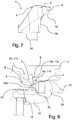
Fig. 7 shows a side view of a striker plate in accordance with an embodiment of the present invention; -
Fig. 8 shows a partial, cross-sectional side view of a window in accordance with an embodiment of the present invention; -
Fig. 9 shows a perspective top view of a striker plate in accordance with an embodiment of the present invention; -
Fig. 10 shows a further perspective top view of a striker plate in accordance with an embodiment of the present invention; -
Fig. 11 shows a bottom view of a striker plate in accordance with an embodiment of the present invention; -
Fig. 12 shows several cross-sectional side views of a striker plate in accordance with an embodiment of the present invention, each cross-section being made at different locations; -
Fig. 13 shows a partial, cross-sectional side view of a window in accordance with an embodiment of the present invention; -
Fig. 14 shows a partial, cross-sectional side view of a window in accordance with an embodiment of the present invention. -
Fig. 1 shows awindow 14 comprising awindow sash 10 and awindow frame 11 adapted for receiving thewindow sash 10. Thewindow frame 11 and thewindow sash 10 both comprise of parallel opposite upright members and parallel opposite horizontal members. Thewindow 14 may be any kind of window but is preferably a roof window. By "roof window" is meant a window arranged in a roof structure, preferably a window arranged such the main plane of the window is inclined/tilted, i.e., having substantially the same pitch as the roof window. Nevertheless, completely vertically extending windows, arranged in a façade or as a dormer window in a roof structure, are also possible. -
Fig. 1 illustrates the window as it could be mounted in an inclined building roof and with the window sash in the open position. The invention can be equally applied also to bottom or top hung window assemblies, including such mounted in a substantially vertical façade. Preferably, the frame members and sash members are for the major part wooden, although it is also possible to use metal or plastic members. When the window is closed, i.e., thesash 10 is in a closed position, thesash 10 is oriented substantially parallel with theframe 11 as shown inFig. 8 which is a partial cross-sectional view through the window. - The
window sash 10 has a windowpane and is pivotally mounted to theframe 11 by means of pivotal hinges. The hinges may be located substantially halfway between the upper and lower horizontal members of thewindow sash 10. Thewindow sash 10 may be configured to pivot around a pivot axis A so as to open thesash 10 at least partially towards an inside of the window, as sown inFig. 1 . The pivot axis A is parallel with the horizontal sash members and the horizontal frame members. Thewindow 14 may, e.g., be a top hung window or a center pivot window. - The
window 14 further comprises alock assembly 9 described in more detail below, which lockassembly 9 is used to lock thewindow sash 10 to thewindow frame 11. As shown inFig. 1 , thelock assembly 9, preferably thelock mechanism 13 shown inFig. 8 , may comprise a manuallyoperable handle 15. - The window may further comprise, shown in
Fig. 8 , aventilation flap 16 pivotally connected to thesash 10 and covering a ventilation passage through the window sash, as theventilation flap 16 is in a closed position. In such an embodiment, thehandle 15 is operatively connected to theventilation flap 16 for controlling the position of thelock assembly 9 as well as the position of theventilation flap 16. - The window may also comprise an electric actuator (not shown), the actuator being configured to operate the
lock assembly 9. -
Fig. 2 shows a priorart striker plate 1 for engagement with a lockingpawl 12,striker plate 1 being configured such that the free end of thepivotable locking pawl 12 can be received in a slot formed between two protruding parts of thestriker plate 1. -
Figs. 3 to 7 show one embodiment of astriker plate 1 for interlocking engagement with a lockingpawl 12.Figs. 9 to 12 show a further embodiment of astriker plate 1 for interlocking engagement with a lockingpawl 12. Thestriker plate 1 is preferably a single-piece element, i.e., is manufactured as a single element that neither requires assembly, fitting, or interaction of several parts. - The
striker plate 1 comprises a substantiallyflat base 2, i.e., the main surface S is substantially planar, and thebase 2 may comprise a first part and a second part. The first part and the second part may both comprise half of thebase 2, but the base area may be distributed between the first part and the second part in any other suitable manner. The first part may comprise at least a firstperipheral edge 2a of thebase 2, and the second part may comprise at least a secondperipheral edge 2b of thebase 2. The firstperipheral edge 2a and the secondperipheral edge 2b may extend along opposite edges ofbase 2 and may also extend substantially in parallel. - The first
peripheral edge 2a and the secondperipheral edge 2b of thestriker plate 1 may be configured to extend substantially in parallel with a top window frame member, a bottom window frame member, and/or the pivot axis A. of thewindow 14. - The first
peripheral edge 2a and the secondperipheral edge 2b are connected by two further peripheral edges extending substantially transverse to the firstperipheral edge 2a and the secondperipheral edge 2b, i.e., the two further peripheral edges extend across both the first part and the second part of thebase 2. Hence, the base may have a substantially rectangular shape, however, any other suitable form is possible such as square frustum. The substantiallyflat base 2 has a first face 2c and an oppositesecond face 2d, the faces being delimited by the peripheral edges of thebase 2. - At least one
abutment element 3 protrudes from the main surface S of thebase 2 in a first direction D1. Theabutment element 3 may protrude at least partially from the first part of thebase 2, preferably from the first face 2c in a direction away from thesecond face 2d, and even more preferably from an area immediately adjacent the firstperipheral edge 2a of thebase 2. As shown in the Figs., preferably oneabutment element 3 is arranged at each of the two corners of the first part of thebase 2, i.e., eachabutment element 3 extends at least partially along the firstperipheral edge 2a and one of the two further peripheral edges. - The
abutment element 3 comprises afirst face 3a defining an abutment area configured to engage the lockingpawl 12. Thefirst face 3a may face towards the second part of thebase 2. Asecond face 3b of theabutment element 3 is essentially directed in an opposite direction than thefirst face 3a, i.e., thesecond face 3b may face away from the second part of thebase 2. - The
abutment element 3 forms a solitary wall protruding from thebase 2, as shown in the Figs. and is not formed as a recessed section of thebase 2. - The
striker plate 1 further comprises areinforcement arrangement 4 which may protrude from thesecond face 3b of theabutment element 3, as shown inFigs. 3 to 7 , and/or from the firstperipheral edge 2a of thebase 2, as shown inFig. 8 . - Furthermore, the
reinforcement arrangement 4 may be integrated with theabutment element 3 and at least partially form thesecond face 3b of theabutment element 3, as shown inFigs. 9 to 12 . - The
reinforcement arrangement 4 may, in one example, be a body protruding from theabutment element 3 or a body that abuts theabutment element 3. Such a body may comprise one or more ribs, flanges, or gussets, or may be shaped as a boss. For example, a flange may be connected to the abutment element by a rib (not shown). Preferably, thereinforcement arrangement 4 comprises at least one substantiallyflat surface 4a configured to abut a surface of theframe 11. - The
surface 4a of thereinforcement arrangement 4 and thesecond face 2d of thebase 2 extend substantially in parallel, while the firstperipheral edge 2a of thebase 2 extends at an angle to surface 4a andsecond face 2d, e.g., 90°. This allows the firstperipheral edge 2a ofbase 2 andreinforcement arrangement 4 to form a step with regards to thesecond face 2d ofbase 2. - The
striker plate 1 may comprise a plurality ofthroughgoing openings fastener 8, such as a screw, pin, or bolt, configured to attach thestriker plate 1 to awindow sash 10 or awindow frame 11. Each opening 7 may extend in a first direction D1 substantially parallel with theabutment element 3 and/or the firstperipheral edge 2a, as indicated inFig. 14 . Thestriker plate 1 may comprise four to sixthroughgoing openings striker plate 1 may, in other words, be attached to theframe 11 by means ofseveral fasteners 8 extending through a corresponding number ofopenings striker plate 1. Theopenings striker plate 1, e.g., fouropenings 7a may extend through thebase 2 and oneopening 7b may extend through eachreinforcement arrangement 4. - Each
reinforcement arrangement 4 may comprise one of thethroughgoing openings 7b, thethroughgoing opening 7b and acorresponding fastener 8 extending in a second direction D2 as seen from the main surface S, as indicated inFig. 13 . - The second direction D2 may extend at an angle ≤90° to the first direction D1. The
throughgoing openings corresponding fasteners 8 may extend at an acute angle to theabutment element 3. - The second part of the
base 2 may comprise a deformation section, preferably extending adjacent at least one of thethroughgoing openings 7a. The deformation section is configured to allow thebase 2 to undergo plastic deformation when there is an increase in force applied by the lockingpawl 12 onto the abutment area of theabutment element 3. - The
frame 11 may comprise afirst surface 11a, asecond surface 11b, and athird surface 11c, thefirst surface 11a extending between thesecond surface 11b and athird surface 11c. Thesecond surface 11b and thethird surface 11c extend substantially in parallel, while thefirst surface 11a extends at an angle to thesecond surface 11b and thethird surface 11c, e.g., 90°. This allows thefirst surface 11a and thesecond surface 11b to form a step with regards to thethird surface 11c. - When the window is closed, i.e., the
sash 10 is in a closed position against theframe 11, thebase 2 of thestriker plate 1 may abut at least thefirst surface 11a, while thereinforcement arrangement 4 may abut thesecond surface 11b. In one embodiment, firstperipheral edge 2a of thebase 2 abuts thefirst surface 11a of theframe 11. Thesecond face 2d of thebase 2 abuts, or extends adjacent, thethird surface 11c of theframe 11. The substantiallyflat surface 4a of thereinforcement arrangement 4 abuts thesecond surface 11b of theframe 11. - The
striker plate 1 may further comprise a guidingwall 5, the guidingwall 5 protruding from an area of the main surface S of thebase 2 located between thesecond edge 2b and theabutment element 3. The guidingwall 5 comprises aguide surface 5a facing towards theabutment element 3, such that aslot 6 is formed between theguide surface 5a and theabutment element 3, theslot 6 being configured for receiving the lockingpawl 12. - The
striker plate 1 may comprise at least one of polypropylene and polyamide material, it may also contain fibers used as fiber reinforcement. Thereinforcement arrangement 4 is preferably manufactured as one integral piece together with thebase 2, theabutment element 3, and optionally the guidingwall 5. - The present invention also relates to a
lock assembly 9 for locking thewindow sash 10 to thewindow frame 11, as shown inFigs. 8 ,13, and 14 . Thelock assembly 9 comprises at least onemoveable locking pawl 12 and astriker plate 1 according to the above. Each lockingpawl 12 is moveable between an unlocked position and a locked position, and is configured to engage the abutment area of oneabutment element 3 of thestriker plate 1 when in the locked position. - As shown in the Figs., a
first locking pawl 12 may be configured to engage afirst abutment element 3 and asecond locking pawl 12 may be configured to engage asecond abutment element 3. Thefirst locking pawl 12 and thesecond locking pawl 12 are configured to pivot simultaneously, and in opposite directions, when moving between the unlocked position and the locked position. - The
striker plate 1 may be configured for attachment to thewindow frame 11, and the lockingpawl 12 may be configured for attachment to thewindow sash 10. Thestriker plate 1 may be attached to thewindow frame 11 such that the first part of thebase 2 faces thewindow frame 11 and the second part of thebase 2 faces thewindow sash 10. Furthermore, thestriker plate 1 may be configured such that thereinforcement arrangement 4 of thestriker plate 1 abuts against thewindow frame 11. In one embodiment, both thebase 2 and thereinforcement arrangement 4 of thestriker plate 1 are configured to be mounted in abutment with thewindow frame 11. - The first end of the locking
pawl 12 may be pivotally connected to thewindow sash 10, and a second end of the lockingpawl 12 may be bent to form apawl member 12a extending at an angle to the rest of the lockingpawl 12. Thepawl member 12a is configured to engage with theslot 6 of thestriker plate 1, i.e., with the abutment area of oneabutment element 3 of thestriker plate 1. - The locking
pawl 12 may be made from plate material, in particular high tensile steel plate material. The lockingpawl 12 may comprise a substantially straight portion that is provided at one end with an aperture receiving a fastening/pivot pin whilst the other end is bent to form thepawl member 12a. Thepawl member 12a may extend at an angle α to the remainder of the lockingpawl 12 in the range of 115 to 120°, such as approximately 118°, which range of angles has been found to give good results for many purposes. - The locking
pawl 12 may furthermore be operatively connected to alock mechanism 13, thelock mechanism 13 being configured to pivot the lockingpawl 12 between the locked position and the unlocked position. - The
lock mechanism 13 may be at least partially surrounded by a casing and may comprise an operator arm which is secured to thehandle 15 of thewindow 14. The mechanism may further comprise an actuator slide. Thelock assembly 9 normally comprises two lockingpawls 12 that are each provided with apawl member 12a at one end. Thepawl members 12a may extend through curved slots in the casing, and project upwards from the casing towards the frame member comprising thestriker plate 1. The actuator slide may extend through a straight slot in the casing and fastening pins may be used for pivotally connecting the lockingpawls 12 to the casing. - In the unlocked position of the
lock assembly 9, each lockingpawl 12 has been turned about its rotation axis in a first direction, into a position with thepawl member 12a not in the abutment area of theabutment element 3. Hence, the upper member of thewindow sash 10 is free to move to the right, inFig. 8 , by turning thewindow sash 10 about pivot axis A to, e.g., the position shown inFig. 1 . - As the
window sash 10 is turned towards the closed position from the open position shown inFig. 1 , eachpawl member 12a approaches thestriker plate 1, whereby the lockingpawls 12 are urged to turn about their rotation axes in a counter-direction towards their locking position. In the locking position, eachpawl member 12a touches the abutment area of arespective abutment element 3. - In one embodiment, shown in
Fig. 8 , the firstperipheral edge 2a of thebase 2 of thelock assembly 9 abuts against thefirst surface 11a of theframe 11, and thereinforcement arrangement 4 abuts against thesecond surface 11b of theframe 11. Thefirst surface 11a and thesecond surface 11b extend in parallel with the pivot axis A. Furthermore, thesecond surface 11b extends at an angle, e.g., 90° to thefirst surface 11a such that thefirst surface 11a and thesecond surface 11b together form a step. - The
pawl member 12a may be provided with narrow sides that converge towards the tip of thepawl member 12a for facilitating entry of thepawl member 12a intoslot 6 of thestriker plate 1. Entry of thepawl members 12a, into theslots 6, happens as the lockingpawls 12 turn about their rotation axes while they are simultaneously being moved with thesash 10 towards theframe 11 when turning thesash 10 about pivot axis A to the closed position. The portion of thepawl member 12a which is closest to the bend of the lockingpawl 12 may be profiled to improve the resistance of thepawl member 12a against bending over when a large force is applied to the abutment area of thepawl member 12a, as could happen when a burglar seeks to open thewindow 14 by applying a force onto thesash 10 to the right inFig. 8 . - Such a force, i.e., a force applied onto the
sash 10 in a window opening direction, such as a force applied from the outside by a burglar or from the inside by a person or other large object falling onto the window, generates a counterforce when the lockingpawl 12 is in the locked position, which counterforce prevents thesash 10 from opening. The counterforce is generated by means of theabutment element 3, engaging the lockingpawl 12, and thereinforcement arrangement 4, fixed to theframe 11 by means offastener 8 and abutting thewindow frame 11. - The various aspects and implementations have been described in conjunction with various embodiments herein. However, other variations to the disclosed embodiments can be understood and effected by those skilled in the art in practicing the claimed subject-matter, from a study of the drawings, the disclosure, and the appended claims. In the claims, the word "comprising" does not exclude other elements or steps, and the indefinite article "a" or "an" does not exclude a plurality. A single processor or other unit may fulfill the functions of several items recited in the claims. The mere fact that certain measures are recited in mutually different dependent claims does not indicate that a combination of these measured cannot be used to advantage. A computer program may be stored/distributed on a suitable medium, such as an optical storage medium or a solid-state medium supplied together with or as part of other hardware, but may also be distributed in other forms, such as via the Internet or other wired or wireless telecommunication systems.
- The reference signs used in the claims shall not be construed as limiting the scope. Unless otherwise indicated, the drawings are intended to be read (e.g., cross-hatching, arrangement of parts, proportion, degree, etc.) together with the specification, and are to be considered a portion of the entire written description of this disclosure. As used in the description, the terms "horizontal", "vertical", "left", "right", "up" and "down", as well as adjectival and adverbial derivatives thereof (e.g., "horizontally", "rightwardly", "upwardly", etc.), simply refer to the orientation of the illustrated structure as the particular drawing figure faces the reader. Similarly, the terms "inwardly" and "outwardly" generally refer to the orientation of a surface relative to its axis of elongation, or axis of rotation, as appropriate.
Claims (16)
- A striker plate (1) for interlocking engagement with at least one locking pawl (12), said striker plate (1) comprising:- a base (2) having a main surface (S) delimited by at least a first peripheral edge (2a) and a second peripheral edge (2b),- at least one abutment element (3) protruding from said main surface in a first direction (D1),
said abutment element (3) comprising a first face (3a) defining an abutment area configured to engage said locking pawl (12), and- a reinforcement arrangement (4)said reinforcement arrangement (4) protruding from a second face (3b) of said abutment element (3) or
being integrated with said abutment element (3) and at least partially forming said second face (3b) of said abutment element (3). - The striker plate (1) according to claim 1, wherein said striker plate (1) is a single-piece element.
- The striker plate (1) according to claim 1 or 2, wherein said base (2) comprises a first part and a second part, said first part comprising said first peripheral edge (2a) and said second part comprising said second peripheral edge (2b), said abutment element (3) protruding at least partially from said first part of said base (2).
- The striker plate (1) according to claim 3, wherein said first face (3a) of said abutment element (3) faces towards said second part of said base (2) and/or said second face (3b) of said abutment element (3) faces away from said second part of said base (2).
- The striker plate (1) according to any one of the previous claims, wherein said striker plate (1) comprises a plurality of throughgoing openings (7a, 7b), each opening being configured to receive a fastener (8) configured to attach said striker plate (1) to a window sash (10) or a window frame (11).
- The striker plate (1) according to claim 5, comprising four to six throughgoing openings (7a, 7b).
- The striker plate (1) according to claim 5 or 6, wherein said reinforcement arrangement (4) comprises one of said throughgoing openings (7b), said throughgoing opening (7b) and said fastener (8) extending in a second direction (D2) as seen from said main surface (S).
- The striker plate (1) according to any one of claims 3 to 7, wherein said second part of said base (2) comprises a deformation section, preferably extending adjacent at least one of said throughgoing openings (7a), said deformation section being configured to allow the base (2) to undergo plastic deformation when there is an increase in force applied by said locking pawl (12) onto said abutment area of said abutment element (3).
- The striker plate (1) according to any one of the previous claims, further comprising a guiding wall (5), said guiding wall (5) protruding from an area of said main surface (S) of said base (2) located between said second peripheral edge (2b) and said abutment element (3),
said guiding wall (5) comprising a guide surface (5a) facing towards said abutment element (3), a slot (6) being formed between said guide surface (5a) and said abutment element (3), said slot (6) being configured for receiving said locking pawl (12). - A lock assembly (9) for locking a window sash (10) to a window frame (11), said lock assembly (9) comprising at least one moveable locking pawl (12) and a striker plate (1) according to any one of the previous claims,
said locking pawl (12) being moveable between an unlocked position and a locked position, each locking pawl (12) engaging the abutment area of one abutment element (3) of said striker plate (1) when in said locked position. - The lock assembly (9) according to claim 9, comprising a first locking pawl (12) configured to engage a first abutment element (3) and a second locking pawl (12) configured to engage a second abutment element (3), said first locking pawl (12) and said second locking pawl (12) being configured to pivot simultaneously, and in opposite directions, when moving between said unlocked position and said locked position.
- The lock assembly (9) according to claims 10 or 11, wherein said locking pawl (12) is operatively connected to a lock mechanism (13), said lock mechanism (13) being configured to pivot said locking pawl (12) between said locked position and said unlocked position.
- A window (14) comprising a window sash (10) and a window frame (11) adapted for receiving said window sash (10), said window (14) further comprising the lock assembly (9) according to any one of claims 10 to 12, said window sash (10) being locked to said window frame (11) by means of said lock assembly (9).
- The window (14) according to claim 13, wherein a first end of the locking pawl (12) of said lock assembly (9) is pivotally connected to said window sash (10), and a second end of said locking pawl (12) is bent to form a pawl member (12a) extending at an angle to the rest of said locking pawl (12), said pawl member (12a) being configured to engage with the abutment area of one abutment element (3) of said striker plate (1).
- The window according to any claim 13 or 14, wherein the base (2) and the reinforcement arrangement (4) of the striker plate (1) of said lock assembly (9) are configured to be mounted in abutment with said window frame (11),
a force applied onto said window sash (10) in a window opening direction generating a counterforce when said locking pawl (12) is the locked position, preventing said window sash (10) from opening,
said counterforce being generated by means of said locking pawl (12) engaging said locking wall (3) and said reinforcement arrangement (4) abutting said window frame (11) . - The window according to any one of claims 13 to 15, wherein the first peripheral edge (2a) of the base (2) of said lock assembly (9) is configured to abut against a first surface (11a) of said window frame (11), and
said reinforcement arrangement (4) is configured to abut against a second surface (11b) of said window frame (11), said first surface (11a) and said second surface (11b) extending parallel with a pivot axis (A) of said window sash (10), and
said second surface (11b) extending at an angle to said first surface (11a).
Applications Claiming Priority (1)
| Application Number | Priority Date | Filing Date | Title |
|---|---|---|---|
| EP20151165 | 2020-01-10 |
Publications (2)
| Publication Number | Publication Date |
|---|---|
| EP3848540A1 true EP3848540A1 (en) | 2021-07-14 |
| EP3848540B1 EP3848540B1 (en) | 2024-06-05 |
Family
ID=69157721
Family Applications (1)
| Application Number | Title | Priority Date | Filing Date |
|---|---|---|---|
| EP21150853.6A Active EP3848540B1 (en) | 2020-01-10 | 2021-01-11 | A striker plate for a lock assembly, said lock assembly, and a window comprising said lock assembly |
Country Status (1)
| Country | Link |
|---|---|
| EP (1) | EP3848540B1 (en) |
Citations (6)
| Publication number | Priority date | Publication date | Assignee | Title |
|---|---|---|---|---|
| WO2001096699A1 (en) * | 2000-06-13 | 2001-12-20 | Vkr Holding A/S | System for windows, doors and the like |
| CN2789394Y (en) * | 2005-01-07 | 2006-06-21 | 青岛安日达工贸有限公司 | Sloping window |
| WO2010027288A1 (en) | 2008-09-04 | 2010-03-11 | Fakro Pp Spolka Z O. O. | Catch for handle bolt, particularly for roof windows |
| EP2607578A1 (en) | 2011-12-22 | 2013-06-26 | VKR Holding A/S | A lock assembly and a striking plate |
| EP2826934A2 (en) | 2013-07-19 | 2015-01-21 | FAKRO PP Sp. z o.o. | Deadbolt socket assembly in a frame, having an increased break-in resistance |
| EP2947239A1 (en) * | 2014-05-22 | 2015-11-25 | Roto Frank Ag | Actuating system for a building closure and building closure with an actuation device |
-
2021
- 2021-01-11 EP EP21150853.6A patent/EP3848540B1/en active Active
Patent Citations (6)
| Publication number | Priority date | Publication date | Assignee | Title |
|---|---|---|---|---|
| WO2001096699A1 (en) * | 2000-06-13 | 2001-12-20 | Vkr Holding A/S | System for windows, doors and the like |
| CN2789394Y (en) * | 2005-01-07 | 2006-06-21 | 青岛安日达工贸有限公司 | Sloping window |
| WO2010027288A1 (en) | 2008-09-04 | 2010-03-11 | Fakro Pp Spolka Z O. O. | Catch for handle bolt, particularly for roof windows |
| EP2607578A1 (en) | 2011-12-22 | 2013-06-26 | VKR Holding A/S | A lock assembly and a striking plate |
| EP2826934A2 (en) | 2013-07-19 | 2015-01-21 | FAKRO PP Sp. z o.o. | Deadbolt socket assembly in a frame, having an increased break-in resistance |
| EP2947239A1 (en) * | 2014-05-22 | 2015-11-25 | Roto Frank Ag | Actuating system for a building closure and building closure with an actuation device |
Also Published As
| Publication number | Publication date |
|---|---|
| EP3848540B1 (en) | 2024-06-05 |
Similar Documents
| Publication | Publication Date | Title |
|---|---|---|
| US9234374B2 (en) | Integrated lock and latch device for sliding windows | |
| EP3252255B1 (en) | A hinge for a window, a window including a set of such hinges, and a method of installing such a window | |
| US9702173B2 (en) | FER locking system for sliding windows | |
| US20160319577A1 (en) | Double-action, adjustable, after-market sash stop | |
| US6170305B1 (en) | Interconnect mechanism for dual lock | |
| EP3848540A1 (en) | A striker plate for a lock assembly, said lock assembly, and a window comprising said lock assembly | |
| WO2012037202A1 (en) | Latch jamb security plate for doorjamb | |
| EP2607578B1 (en) | A lock assembly and a striking plate | |
| KR102347158B1 (en) | Safety locking device for door handle | |
| EP3091150B1 (en) | A lock assembly | |
| WO2002033204A1 (en) | A restrictor device | |
| AU2002211125A1 (en) | A restrictor device | |
| WO2005042903A1 (en) | Shutter curtain lifting prevention structure in shutter device | |
| EP0777030A1 (en) | Sliding door and handling jamb therefor | |
| EP3872277B1 (en) | A roof window with an opening restrictor for limiting the opening of a roof window | |
| US20090107190A1 (en) | Container locking systems | |
| EP3124725B1 (en) | A window with an opening restrictor having an activation part | |
| US20050035606A1 (en) | Handle for opening and closing shoji | |
| JP4056873B2 (en) | Window shutter device | |
| KR102555731B1 (en) | Turn locking device for system windows | |
| JP3802017B2 (en) | Crescent tablets | |
| JPS634795Y2 (en) | ||
| JP4547609B2 (en) | Lifting prevention structure of shutter curtain in shutter device | |
| JP3870372B2 (en) | shutter | |
| JP4201660B2 (en) | Crescent tablets |
Legal Events
| Date | Code | Title | Description |
|---|---|---|---|
| PUAI | Public reference made under article 153(3) epc to a published international application that has entered the european phase |
Free format text: ORIGINAL CODE: 0009012 |
|
| STAA | Information on the status of an ep patent application or granted ep patent |
Free format text: STATUS: THE APPLICATION HAS BEEN PUBLISHED |
|
| AK | Designated contracting states |
Kind code of ref document: A1 Designated state(s): AL AT BE BG CH CY CZ DE DK EE ES FI FR GB GR HR HU IE IS IT LI LT LU LV MC MK MT NL NO PL PT RO RS SE SI SK SM TR |
|
| STAA | Information on the status of an ep patent application or granted ep patent |
Free format text: STATUS: REQUEST FOR EXAMINATION WAS MADE |
|
| 17P | Request for examination filed |
Effective date: 20211125 |
|
| RBV | Designated contracting states (corrected) |
Designated state(s): AL AT BE BG CH CY CZ DE DK EE ES FI FR GB GR HR HU IE IS IT LI LT LU LV MC MK MT NL NO PL PT RO RS SE SI SK SM TR |
|
| STAA | Information on the status of an ep patent application or granted ep patent |
Free format text: STATUS: EXAMINATION IS IN PROGRESS |
|
| 17Q | First examination report despatched |
Effective date: 20230912 |
|
| GRAP | Despatch of communication of intention to grant a patent |
Free format text: ORIGINAL CODE: EPIDOSNIGR1 |
|
| STAA | Information on the status of an ep patent application or granted ep patent |
Free format text: STATUS: GRANT OF PATENT IS INTENDED |
|
| RIC1 | Information provided on ipc code assigned before grant |
Ipc: E05B 47/00 20060101ALN20240220BHEP Ipc: E05C 3/08 20060101ALI20240220BHEP Ipc: E05B 15/02 20060101AFI20240220BHEP |
|
| INTG | Intention to grant announced |
Effective date: 20240314 |
|
| GRAS | Grant fee paid |
Free format text: ORIGINAL CODE: EPIDOSNIGR3 |
|
| GRAA | (expected) grant |
Free format text: ORIGINAL CODE: 0009210 |
|
| STAA | Information on the status of an ep patent application or granted ep patent |
Free format text: STATUS: THE PATENT HAS BEEN GRANTED |