EP3848306A1 - Sorting facility - Google Patents
Sorting facility Download PDFInfo
- Publication number
- EP3848306A1 EP3848306A1 EP20217787.9A EP20217787A EP3848306A1 EP 3848306 A1 EP3848306 A1 EP 3848306A1 EP 20217787 A EP20217787 A EP 20217787A EP 3848306 A1 EP3848306 A1 EP 3848306A1
- Authority
- EP
- European Patent Office
- Prior art keywords
- traveling
- power generation
- carriages
- carriage
- belt conveyor
- Prior art date
- Legal status (The legal status is an assumption and is not a legal conclusion. Google has not performed a legal analysis and makes no representation as to the accuracy of the status listed.)
- Granted
Links
Images


Classifications
-
- B—PERFORMING OPERATIONS; TRANSPORTING
- B65—CONVEYING; PACKING; STORING; HANDLING THIN OR FILAMENTARY MATERIAL
- B65G—TRANSPORT OR STORAGE DEVICES, e.g. CONVEYORS FOR LOADING OR TIPPING, SHOP CONVEYOR SYSTEMS OR PNEUMATIC TUBE CONVEYORS
- B65G47/00—Article or material-handling devices associated with conveyors; Methods employing such devices
- B65G47/74—Feeding, transfer, or discharging devices of particular kinds or types
- B65G47/94—Devices for flexing or tilting travelling structures; Throw-off carriages
- B65G47/96—Devices for tilting links or platform
-
- B—PERFORMING OPERATIONS; TRANSPORTING
- B07—SEPARATING SOLIDS FROM SOLIDS; SORTING
- B07C—POSTAL SORTING; SORTING INDIVIDUAL ARTICLES, OR BULK MATERIAL FIT TO BE SORTED PIECE-MEAL, e.g. BY PICKING
- B07C3/00—Sorting according to destination
- B07C3/02—Apparatus characterised by the means used for distribution
- B07C3/08—Apparatus characterised by the means used for distribution using arrangements of conveyors
- B07C3/082—In which the objects are carried by transport holders and the transport holders form part of the conveyor belts
-
- B—PERFORMING OPERATIONS; TRANSPORTING
- B65—CONVEYING; PACKING; STORING; HANDLING THIN OR FILAMENTARY MATERIAL
- B65G—TRANSPORT OR STORAGE DEVICES, e.g. CONVEYORS FOR LOADING OR TIPPING, SHOP CONVEYOR SYSTEMS OR PNEUMATIC TUBE CONVEYORS
- B65G35/00—Mechanical conveyors not otherwise provided for
-
- B—PERFORMING OPERATIONS; TRANSPORTING
- B65—CONVEYING; PACKING; STORING; HANDLING THIN OR FILAMENTARY MATERIAL
- B65G—TRANSPORT OR STORAGE DEVICES, e.g. CONVEYORS FOR LOADING OR TIPPING, SHOP CONVEYOR SYSTEMS OR PNEUMATIC TUBE CONVEYORS
- B65G43/00—Control devices, e.g. for safety, warning or fault-correcting
-
- B—PERFORMING OPERATIONS; TRANSPORTING
- B65—CONVEYING; PACKING; STORING; HANDLING THIN OR FILAMENTARY MATERIAL
- B65G—TRANSPORT OR STORAGE DEVICES, e.g. CONVEYORS FOR LOADING OR TIPPING, SHOP CONVEYOR SYSTEMS OR PNEUMATIC TUBE CONVEYORS
- B65G47/00—Article or material-handling devices associated with conveyors; Methods employing such devices
- B65G47/52—Devices for transferring articles or materials between conveyors i.e. discharging or feeding devices
- B65G47/68—Devices for transferring articles or materials between conveyors i.e. discharging or feeding devices adapted to receive articles arriving in one layer from one conveyor lane and to transfer them in individual layers to more than one conveyor lane or to one broader conveyor lane, or vice versa, e.g. combining the flows of articles conveyed by more than one conveyor
-
- B—PERFORMING OPERATIONS; TRANSPORTING
- B65—CONVEYING; PACKING; STORING; HANDLING THIN OR FILAMENTARY MATERIAL
- B65G—TRANSPORT OR STORAGE DEVICES, e.g. CONVEYORS FOR LOADING OR TIPPING, SHOP CONVEYOR SYSTEMS OR PNEUMATIC TUBE CONVEYORS
- B65G2203/00—Indexing code relating to control or detection of the articles or the load carriers during conveying
- B65G2203/02—Control or detection
- B65G2203/0266—Control or detection relating to the load carrier(s)
- B65G2203/0283—Position of the load carrier
-
- B—PERFORMING OPERATIONS; TRANSPORTING
- B65—CONVEYING; PACKING; STORING; HANDLING THIN OR FILAMENTARY MATERIAL
- B65G—TRANSPORT OR STORAGE DEVICES, e.g. CONVEYORS FOR LOADING OR TIPPING, SHOP CONVEYOR SYSTEMS OR PNEUMATIC TUBE CONVEYORS
- B65G2203/00—Indexing code relating to control or detection of the articles or the load carriers during conveying
- B65G2203/02—Control or detection
- B65G2203/0266—Control or detection relating to the load carrier(s)
- B65G2203/0291—Speed of the load carrier
Definitions
- the present invention relates to sorting facility that sorts articles by belt conveyors provided in traveling carriages traveling along a conveyance path.
- the sorting facility in Japanese Patent Laid-Open No. 2018-122985 sorts articles by running a plurality of traveling carriages connected endlessly along a loop-shaped conveyance path.
- the traveling carriages each include a belt conveyor where an article can be placed.
- the traveling carriages each receive an article transferred from a loading conveyor provided beside the conveyance path into the belt conveyor.
- the traveling carriages convey the received articles to a predetermined position, the traveling carriages each deliver the received article to a delivery conveyor provided beside the conveyance path by driving the belt conveyor.
- the traveling carriages are driven by friction drive type driving devices provided at predetermined positions of the conveyance path, and between a pair of rails.
- the traveling carriage has traveling wheels rotating while sliding in contact with the rails during traveling.
- the belt conveyor is driven by a driving motor provided in the traveling carriage.
- the driving motor drives the belt conveyor based on electric power supplied from a power generation device provided in the traveling carriage.
- the power generation device generates electric power by a rotary shaft fixed to the traveling wheels rotating by travelling of the traveling carriage.
- the driving devices for running the traveling carriages provided in the predetermined positions of the conveyance path are driven, while in order to drive the belt conveyors, the traveling carriages are run to cause the power generation devices to generate electric power, and the driving motors are driven by the generated electric power.
- the traveling carriages are run to cause the power generation devices to generate electric power, and the driving motors are driven by the generated electric power.
- the driving devices need to output a force equal to or more than the driving force necessary to run all the traveling carriages in the equipment at a time of actuation. Therefore, an excessive load is exerted on the driving devices at the time of actuation, and it is impossible to distribute the driving force necessary to run the traveling carriages sufficiently to the traveling carriages. Consequently, there has unfortunately been the problem of being unable to run the traveling carriages stably at the time of actuation of the traveling carriages.
- the present invention has an object to provide sorting facility that can reduce a load on driving device for running traveling carriages at a time of actuation of traveling carriages having belt conveyors sorting articles.
- sorting facility of the present invention is sorting facility sorting an article by a belt conveyor provided on a traveling carriage traveling along a conveyance path, wherein a plurality of the traveling carriages travel on the conveyance path, each of the plurality of the traveling carriages is provided with a power generation device generating electric power by traveling of the traveling carriage, the belt conveyor provided on each of the plurality of the traveling carriages is driven in a driving position provided in a predetermined position on the conveyance path by the electric power generated by the power generation device, and the power generation device provided in each of the plurality of the traveling carriages starts generation of electric power necessary to drive the belt conveyor in order from the power generation device provided in the traveling carriage scheduled to pass the driving position first after the plurality of the traveling carriages are actuated and traveling speeds of the plurality of the traveling carriages are kept constant at a predetermined speed.
- generation of the electric power necessary to drive the belt conveyor is started in order from the power generation device provided in the traveling carriage scheduled to pass the driving position first, after the plurality of traveling carriages are actuated and the traveling speeds of the plurality of traveling carriages are kept constant at the predetermined speed. That is to say, power generation of the power generation device by traveling of the traveling carriage (driving force of the driving device for running the traveling carriage) is started in order from the power generation device provided in the traveling carriage scheduled to pass the position for driving the belt conveyor on the traveling carriage first, after the plurality of traveling carriages are actuated and the traveling speeds are kept constant at the predetermined speed.
- the sorting facility of the present invention is the above described sorting facility, wherein the power generation device starts generation of the electric power necessary to drive the belt conveyor by the traveling carriage provided with the power generation device traveling to a position at an upstream side from the driving position after the plurality of the traveling carriages are actuated and the traveling speeds are kept constant at the predetermined speed.
- generation of the electric power necessary to drive the belt conveyor is started by the traveling carriage provided with the power generation device traveling to the upstream side from the driving position, after the plurality of traveling carriages are actuated and the traveling speeds are kept constant at the predetermined speed.
- power generation of the power generation device by traveling of the traveling carriage driving force of the driving device for running the traveling carriage
- the sorting facility of the present invention is the above described sorting facility, wherein a ground side communication device communicable with the power generation device is provided in a position at an upstream side from the driving position, and the power generation device starts generation of the electric power necessary to drive the belt conveyor by the traveling carriage provided with the power generation device traveling to the position at the upstream side from the driving position and receiving a signal from the ground side communication device after the plurality of traveling carriages are actuated and the traveling speeds are kept constant at the predetermined speed.
- generation of the electric power necessary to drive the belt conveyor is started by the signal from the ground side communication device provided at the upstream side from the driving position.
- power generation of the power generation device by traveling of the traveling carriage is started after the plurality of traveling carriages are actuated, and the traveling speeds are kept constant at the predetermined speed, and is started by the signal from the ground side communication device provided at the upstream side from the driving position.
- the sorting facility of the present invention is the above described sorting facility, wherein the driving position is any of a loading position for loading an article onto the belt conveyor, an adjustment position being a position at a downstream side from the loading position and for adjusting a placement location of the article on the belt conveyor, and a delivery position being a position at a downstream side from the adjustment position and for delivering the article on the belt conveyor.
- generation of the electric power necessary to drive the belt conveyor is started by the traveling carriage traveling to any position of the position at the upstream side from the loading position of the article to the belt conveyor, the position at the upstream side from the delivery position of the article from the belt conveyor, and the position at the upstream side from the adjustment position for adjusting the placement location of the article on the belt conveyor, after the plurality of traveling carriages are actuated and the traveling speeds are kept constant at the predetermined speed.
- power generation of the power generation device by traveling of the traveling carriage is started by traveling to the position at the upstream side from the position necessary to drive the belt conveyor on the traveling carriage after the plurality of traveling carriages are actuated and the traveling speeds are kept constant at the predetermined speed.
- generation of the electric power necessary to drive the belt conveyor is started in order from the power generation device provided in the traveling carriage scheduled to pass the position (driving position) for driving the belt conveyor on the traveling carriage first, after the plurality of traveling carriages are actuated and the traveling speeds are kept constant at the predetermined speed, and therefore it is possible to distribute timings of power generation of the power generation devices at the time of actuation of the traveling carriages. Accordingly, at the time of actuation of the traveling carriages, the power generation devices provided in all the traveling carriages traveling on the conveyance path do not simultaneously start power generation to drive the belt conveyors, and it is possible to reduce the load on the driving device for running the traveling carriages.
- Sorting facility 10 of the present invention will be described.
- the present invention is not limited to the sorting facility 10 shown as follows.
- a loop-shaped conveyance path K for conveying articles 90 are formed.
- the conveyance path for conveying the articles 90 is not limited to the loop-shaped conveyance path K.
- the sorting facility 10 is mainly composed of a main conveyor device 11 conveying the articles 90 along the conveyance path K, a plurality of induction conveyors 12 inputting the articles 90 onto the conveyance path K of the main conveyor device 11, a plurality of chutes 13 receiving the articles 90 delivered from the conveyance path K of the main conveyor device 11, and an article detection device 55 detecting a placement location of the article 90 on a belt conveyor 23.
- the article 90 is inputted to the traveling carriage 20 traveling along rails 14 (see FIG. 2 ) of the main conveyor device 11 from a predetermined induction conveyor 12.
- the article 90 inputted to the traveling carriage 20 is conveyed along the conveyance path K.
- the article 90 conveyed by the traveling carriage 20 is delivered to the chute 13 assigned to each store, and is sorted by store, for example.
- the article 90 conveyed by the traveling carriage 20 is adjusted so that a placement location on the belt conveyor 23 is in a center position of the belt conveyor 23 based on detection by the article detection device 55, before delivered to the chute 13.
- the devices (the main conveyor device 11, the induction conveyors 12, the chute 13, the article detection device 55) of the sorting facility 10 are connected to a supervisory controller 40 (see FIG. 3 ) controlling the entire sorting facility 10, and are controlled by the supervisory controller 40.
- the traveling carriage 20 with the article 90 placed thereon travels on the rails 14 (see FIG. 2 ), and thereby the article 90 is conveyed along the conveyance path K.
- the induction conveyor 12 inputs the article 90 to the belt conveyor 23 of the traveling carriage 20 traveling on the conveyance path K.
- the plurality of (three in FIG. 1 ) induction conveyors 12 are disposed side by side along the conveyance path K.
- the traveling carriage 20 where the article 90 should be inputted in advance is searched for and determined for each of the induction conveyors 12.
- the induction conveyor 12 inputs the article 90 to the predetermined traveling carriage 20 determined for each of the induction conveyors 12.
- the chute 13 receives the article 90 delivered from the traveling carriage 20, and conveys the received article 90 to different downstream equipment (for example, shipment equipment), directly to a vehicle (for example, a truck), or the like.
- the plurality of (three in FIG. 1 ) chutes 13 are disposed side by side along the conveyance path K.
- the chute 13 receives the article 90 determined in advance for each of the chutes 13 from the traveling carriage 20.
- the article detection device 55 is composed of a plurality of sensors provided above the main conveyor device 11, at a conveyance downstream side of the induction conveyor 12, and at a conveyance upstream side of the chute 13.
- the article detection device 55 detects the placement location of the article 90 placed on the belt conveyor 23, and transmits a detection result to the supervisory controller 40 (see FIG. 3 ).
- the supervisory controller 40 calculates a deviation of the article 90 placed on the belt conveyor 23 from the center position of the belt conveyor 23, based on the detection result from the article detection device 55.
- the supervisory controller 40 controls the belt conveyor 23 so that the belt conveyor 23 moves the article 90 to the center position of the belt conveyor 23 based on the calculated deviation amount.
- the traveling carriage 20 receives the article 90 inputted from the predetermined induction conveyor 12.
- the traveling carriage 20 conveys the received article 90 along the conveyance path K and delivers the article 90 to the predetermined chute 13.
- the traveling carriage 20 is connected to the traveling carriages 20 adjacent to one another in the conveyance path K, and travels on the rails 14 in a state connected to the adjacent traveling carriages 20. In other words, the plurality of traveling carriages 20 connected to one another travel on the conveyance path K.
- the traveling carriage 20 travels by drive of a carriage driving device 50.
- the carriage driving device 50 is a friction drive type driving device.
- the carriage driving device 50 includes pinch rollers 51 contacting both side surfaces of a fin 26 of the traveling carriage 20, timing belts 52 rotating the pinch rollers 51, and driving motors 53 driving the pinch rollers 51.
- the carriage driving device 50 is a driving device transmitting motive power to the traveling carriage 20 by using a frictional force by contact of the pair of pinch rollers 51.
- the carriage driving device 50 causes the rotating pair of pinch rollers 51 to contact both the side surfaces of the fin 26 of the traveling carriage 20.
- the carriage driving device 50 runs the traveling carriage 20 by thrusting the fin 26 forward by a frictional force by contact of the pair of pinch rollers 51.
- a plurality of carriage driving devices 50 are provided in predetermined positions of the conveyance path K, and are provided between a pair of rails 14.
- the carriage driving device 50 is supported by a support frame 15 fixed to the rails 14.
- the carriage driving device 50 is connected to the supervisory controller 40, and is controlled by the supervisory controller 40.
- the traveling carriage 20 mainly includes a body 21 traveling on the rails 14, a cover 22 covering a gap from the adjacent traveling carriage 20, the belt conveyor 23 where the article 90 is placed and supported, and a belt driving device 30 for driving the belt conveyor 23.
- the body 21 mainly includes a wheel 25 for traveling on the rails 14, the fin 26 contacting the pinch rollers 51 of the carriage driving device 50, and a frame 27 supporting components of the traveling carriage 20.
- the fin 26 is a long plate member extended along a longitudinal direction (a traveling direction H of the traveling carriage 20) of the traveling carriage 20.
- the fin 26 is attached to a lower part of the body 21.
- the cover 22 is composed of a plate-shaped member closing the gap between the traveling carriages 20 adjacent to each other in the conveyance path K.
- the cover 22 is fixed to a rear side end portion of the traveling carriage 20 (end portion at a rear side to the traveling direction H of the traveling carriage 20).
- the belt conveyor 23 is provided at an upper part of the body 21.
- the belt conveyor 23 conveys the article 90 placed on a belt 24 in a direction horizontally orthogonal to the traveling direction H of the traveling carriage 20, by the belt 24 being driven by the belt driving device 30.
- the traveling carriage 20 reaches a predetermined induction conveyor 12
- the belt 24 is driven by the belt driving device 30, and thereby the belt conveyor 23 moves the article 90 inputted from the induction conveyor 12 to an appropriate placement location on the belt 24.
- the traveling carriage 20 reaches a predetermined chute 13
- the belt 24 is driven by the belt driving device 30, and thereby the belt conveyor 23 discharges the article 90 placed on the belt 24 in a direction where the chute 13 is located.
- the belt 24 is driven by the belt driving device 30, and thereby the belt conveyor 23 adjusts the placement location of the article 90 to the appropriate position.
- the belt driving device 30 is mainly composed of a belt driving motor 31 for driving the belt 24 of the belt conveyor 23, a power generation motor 32 (an example of a "power generation device") for generating electric power for driving the belt 24 of the belt conveyor 23, a capacitor 33 storing electric power generated by the power generation motor 32, a drive controlling inverter 37 for controlling the belt driving motor 31, a power generation controlling inverter 38 for controlling the power generation motor 32, and a carriage side optical transmission device 39 receiving signals from ground side optical transmission devices 41, 42, 43, 44, 45, and 46 provided on a ground side.
- a power generation motor 32 an example of a "power generation device”
- a capacitor 33 storing electric power generated by the power generation motor 32
- a drive controlling inverter 37 for controlling the belt driving motor 31
- a power generation controlling inverter 38 for controlling the power generation motor 32
- a carriage side optical transmission device 39 receiving signals from ground side optical transmission devices 41, 42, 43, 44, 45, and 46 provided on a ground side.
- the belt driving motor 31 is composed of, for example, a sensor-less servomotor.
- the belt driving motor 31 is connected to the belt conveyor 23, and drives the belt 24 of the belt conveyor 23.
- the belt driving motor 31 is connected to the drive controlling inverter 37, and has the number of revolutions controlled by the drive controlling inverter 37.
- the power generation motor 32 is composed of, for example, a sensor-less servo motor.
- the power generation motor 32 is connected to the wheel 25 of the traveling carriage 20, and generates electric power by a rotary shaft of the power generation motor 32 rotating by rotation of the wheel 25.
- the power generation motor 32 is connected to the power generation controlling inverter 38, and has required torque controlled by the power generation controlling inverter 38.
- the capacitor 33 is connected to the belt driving motor 31 and the power generation motor 32 via the drive controlling inverter 37 and the power generation controlling inverter 38, and stores the electric power generated by the power generation motor 32, and supplies the stored electric power to the belt driving motor 31.
- the drive controlling inverter 37 is connected to the belt driving motor 31, and controls the number of revolutions of the belt driving motor 31.
- the drive controlling inverter 37 is connected to the capacitor 33, and controls the electric power supplied to the belt driving motor 31 from the capacitor 33.
- the power generation controlling inverter 38 is connected to the power generation motor 32, and controls required torque of the power generation motor 32.
- the power generation controlling inverter 38 is connected to the capacitor 33, and controls electric power generated by the power generation motor 32 and stored in the capacitor 33.
- the carriage side optical transmission device 39 is fixed to the frame 27 of the body 21.
- the carriage side optical transmission device 39 receives the signals from the ground side optical transmission devices 41, 42, 43, 44, 45, and 46 provided on the ground side by optical transmission.
- the carriage side optical transmission device 39 is connected to the drive controlling inverter 37 and the power generation controlling inverter 38, and transmits the signals from the ground side optical transmission devices 41, 42, 43, 44, 45, and 46 to the drive controlling inverter 37 and the power generation controlling inverter 38.
- traveling of the traveling carriage 20 and an operation of the belt conveyor 23 are controlled by the supervisory controller 40 provided on the ground side (independently from the traveling carriage 20) and controlling the entire sorting facility 10.
- the traveling carriage 20 is not limited to being directly controlled by the supervisory controller 40 controlling the entire sorting facility 10, and may be controlled by a lower-order controller than the supervisory controller 40.
- the supervisory controller 40 is connected to the ground side optical transmission devices 41, 42, 43, 44, 45, and 46 transmitting signals to the carriage side optical transmission device 39, and makes instructions to the traveling carriages 20 via the ground side optical transmission devices 41, 42, 43, 44, 45, and 46.
- the supervisory controller 40 controls the traveling carriages 20 by optical transmission (wireless).
- the ground side optical transmission devices, 41, 42, 43, 44, 45, and 46 are devices performing optical transmission with the carriage side optical transmission devices 39 provided in the respective traveling carriages 20.
- the ground side optical transmission devices 41, 42, and 43 transmit instruction signals for operating the power generation motor 32 to the power generation controlling inverter 38 to the carriage side optical transmission device 39.
- the power generation controlling inverter 38 operates the power generation motor 32 to cause the power generation motor 32 to start generation of power necessary to drive the belt conveyor 23, by receiving the instruction signals from the ground side optical transmission devices 41, 42 and 43.
- the ground side optical transmission devices 44, 45, and 46 transmit instruction signals for operating the belt driving motor 31 to the drive controlling inverter 37 to the carriage side optical transmission device 39.
- the drive controlling inverter 37 operates the belt driving motor 31 in a drive position provided in the predetermined position in the conveyance path K as a position requiring drive of the belt conveyor 23, and starts driving of the belt 24 of the belt conveyor 23, by receiving the instruction signals from the ground side optical transmission devices 44, 45 and 46.
- the driving position as the position requiring drive of the belt conveyor 23 refers to a position for loading the article 90 onto the belt conveyor 23 from the induction conveyor 12 ("loading position", the position contacting the downstream side of the induction conveyor 12 in the main conveyor device 11), the position for adjusting the placement location of the article 90 on the belt conveyor 23 after the traveling carriage 20 passes through the article detection device 55 (“adjustment position”), and the position for delivering the article 90 on the belt conveyor 23 to the chute 13 (“delivery position", the position contacting the upstream side of the chute 13 in the main conveyor device 11).
- the fourth ground side optical transmission device 44 transmits an instruction signal for driving the belt conveyor 23 when receiving the article 90 inputted from the induction conveyor 12 on the belt conveyor 23 of the traveling carriage 20.
- the drive controlling inverter 37 operates the belt driving motor 31 in the loading position by receiving the instruction signal from the ground side optical transmission device 44.
- the fifth ground side optical transmission device 45 transmits an instruction signal for driving the belt conveyor 23 when adjusting the placement location of the article 90 on the belt conveyor 23 based on the detection result from the article detection device 55.
- the drive controlling inverter 37 operates the belt driving motor 31 in the adjustment position by receiving the instruction signal from the ground side optical transmission device 45.
- the sixth ground side optical transmission device 46 transmits an instruction signal for driving the belt conveyor 23 when delivering the article 90 on the belt conveyor 23 to the chute 13.
- the drive controlling inverter 37 operates the belt driving motor 31 in the delivery position by receiving the instruction signal from the ground side optical transmission device 46.
- the ground side optical transmission devices 41, 42, 43, 44, 45, and 46 are provided along the conveyance path K.
- the first ground side optical transmission device 41 is provided at a conveyance upstream side from a position where the induction conveyor 12 at a most upstream side of the conveyance path K is disposed out of the three induction conveyors 12. In other words, the first ground side optical transmission device 41 is provided at a conveyance upstream side from the loading position (driving position).
- the second ground side optical transmission device 42 is provided at a conveyance downstream side from a position where the induction conveyor 12 at a most downstream side of the conveyance path K out of the three induction conveyors 12 is disposed, and at a conveyance upstream side from the position where the article detection device 55 is disposed. In other words, the second ground side optical transmission device 42 is provided at a position at a conveyance upstream side from the adjustment position (driving position).
- the third ground side optical transmission device 43 is provided at a conveyance downstream side from the position where the article detection device 55 is disposed, and at a conveyance upstream side from a position where the chute 13 at a most upstream side of the conveyance path K out of the three chutes 13 is disposed. In other words, the third ground side optical transmission device 43 is provided at a position at a conveyance upstream side from the delivery position (driving position).
- the fourth ground side optical transmission device 44 is provided at a conveyance upstream side from the position where the induction conveyor 12 at the most upstream side of the conveyance path K out of the three induction conveyors 12 is disposed, and at a conveyance downstream side from a position where the first ground side optical transmission device 41 is disposed.
- the fifth ground side optical transmission device 45 is provided at a conveyance downstream side from the position where the article detection device 55 is disposed, and at a conveyance upstream side from a position where the third ground side optical transmission device 43 is disposed.
- the sixth ground side optical transmission device 46 is provided at a conveyance downstream side from a position where the third ground side optical transmission device 43 is disposed, and at a conveyance upstream side from the position where the chute 13 at the most upstream side of the conveyance path K out of the three chutes 13 is disposed.
- the first ground side optical transmission device 41 is provided at a conveyance upstream side from a position where the fourth ground side optical transmission device 44 is disposed.
- the second ground side optical transmission device 42 is provided at a conveyance upstream side from a position where the fifth ground side optical transmission device 45 is disposed.
- the third ground side optical transmission device 43 is provided at a conveyance upstream side from a position where the sixth ground side optical transmission device 46 is disposed.
- An interval between the first ground side optical transmission device 41 and the fourth ground side optical transmission device 44, an interval between the second ground side optical transmission device 42 and the fifth ground side optical transmission device 45, and an interval between the third ground side optical transmission device 43 and the sixth ground side optical transmission device 46 are set at such distances that the power generation motor 32 can complete generation of electric power necessary to drive the belt conveyor 23 by the time when the traveling carriage 20 reaches the ground side optical transmission devices 44, 45, and 46 after passing the ground side optical transmission devices 41, 42, and 43.
- the interval between the first ground side optical transmission device 41 and the fourth ground side optical transmission device 44, the interval between the second ground side optical transmission device 42 and the fifth ground side optical transmission device 45, and the interval between the third ground side optical transmission device 43 and the sixth ground side optical transmission device 46 are set based on a conveyance speed of the traveling carriage 20 (conveyance capacity of the main conveyor device 11), a power generation capacity of the power generation motor 32, a drive capacity of the belt driving motor 31 and the like.
- the ground side optical transmission devices 41, 42, 43, 44, 45, and 46 transmit instruction signals from the supervisory controller 40 to the carriage side optical transmission device 39 when the traveling carriage 20 passes.
- the traveling carriage 20 travels by drive of the carriage driving device 50. Specifically, the body 21 is thrusted forward by passing the fin 26 of the traveling carriage 20 between the pair of pinch rollers 51 rotating by drive of the driving motor 53 of the carriage driving device 50 and thrusting the fin 26 forward. Thereby, the wheel 25 supported by the body 21 rotates, and the traveling carriage 20 travels. In other words, by drive of the driving motor 53 of the carriage driving device 50, the wheel 25 is indirectly rotated.
- the power generation motor 32 generates electric power necessary to drive the belt conveyor 23 by the traveling carriage 20 traveling on the conveyance path K. Specifically, the power generation motor 32 is driven by the wheel 25 of the traveling carriage 20 rotating for the traveling carriage 20 to travel, and generates the necessary power to drive the belt conveyor 23. In other words, the power generation motor 32 is driven by the wheel 25 being indirectly rotated by drive of the driving motor 53 of the carriage driving device 50. That is to say, the driving force of the driving motor 53 is distributed to traveling of the traveling carriage 20 and power generation of the power generation motor 32.
- all the traveling carriages 20 in the sorting facility 10 stop traveling after all sorting operations in the equipment are finished, or due to a power failure or the like in the equipment.
- all the traveling carriages 20 stopping in the sorting facility 10 are simultaneously actuated.
- all the traveling carriages 20 in the sorting facility 10 travel by the driving force of the driving motor 53.
- the wheels 25 rotate following traveling of the traveling carriages 20, and the power generation motors 32 provided in all the traveling carriages 20 in the sorting facility 10 simultaneously start power generation, the driving forces of the driving motors 53 are distributed to traveling of the traveling carriages 20 and power generation of the power generation motors 32.
- the load on the driving motors 53 at the time of actuation of the traveling carriages 20 is reduced by distributing power generation timings of the power generation motors 32 provided in the respective traveling carriages 20, in the sorting facility 10.
- the predetermined speed is a traveling speed allowing the traveling carriages 20 to travel stably on the conveyance path K, and is a traveling speed set based on degrees of lift of the traveling carriages 20 during travelling, an interval between the adjacent traveling carriages 20 and the like.
- a traveling carriage 20a stops at a conveyance upstream side from the position where the first ground side optical transmission device 41 is disposed before actuation of all the traveling carriages 20 in the sorting facility 10.
- the traveling carriage 20a passes the position where the first ground side optical transmission device 41 is disposed after all the traveling carriages 20 in the sorting facility 10 are actuated and the traveling speeds of all the traveling carriages 20 in the sorting facility 10 are kept constant at the predetermined speed
- the carriage side optical transmission device 39 provided in the traveling carriage 20a receives an instruction signal to operate the power generation motor 32 from the first ground side optical transmission device 41.
- the power generation motor 32 provided in the traveling carriage 20a starts drive based on the instruction signal, and starts generation of electric power necessary to drive the belt conveyor 23.
- a traveling carriage 20b following (at the conveyance upstream side) the traveling carriage 20a passes the position where the first ground side optical transmission device 41 is disposed after all the traveling carriages 20 in the sorting facility 10 are actuated and the traveling speeds of all the traveling carriages 20 in the sorting facility 10 are kept constant at the predetermined speed, the power generation motor 32 provided in the traveling carriage 20b starts drive, and starts generation of electric power necessary to drive the belt conveyor 23.
- the carriage side optical transmission devices 39 provided in the traveling carriages 20a and 20b receive instruction signals to operate the belt driving motors 31 from the fourth ground side optical transmission device 44.
- the belt conveyors 23 provided in the traveling carriages 20a and 20b start drive in the loading position (driving position) based on the instruction signals, and operate the belts 24 of the belt conveyors 23 to receive the articles 90 from the induction conveyor 12.
- a traveling carriage 20c stops at a conveyance upstream side from the position where the second ground side optical transmission device 42 is disposed before actuation of all the traveling carriages 20 in the sorting facility 10.
- the traveling carriage 20c passes the position where the second ground side optical transmission device 42 is disposed after all the traveling carriages 20 in the sorting facility 10 are actuated and the traveling speeds of all the traveling carriages 20 in the sorting facility 10 are kept constant at the predetermined speed
- the carriage side optical transmission device 39 provided in the traveling carriage 20c receives an instruction signal to operate the power generation motor 32 from the second ground side optical transmission device 42.
- the power generation motor 32 provided in the traveling carriage 20c starts power generation based on the instruction signal.
- the power generation motor 32 provided in the traveling carriage 20d starts power generation.
- the carriage side optical transmission devices 39 provided in the traveling carriages 20c and 20d receive the instruction signals to operate the belt driving motors 31 from the fifth ground side optical transmission device 45.
- the belt conveyors 23 provided in the traveling carriages 20c and 20d start drive in the adjustment position (driving position) to operate the belts 24 of the belt conveyors 23, and thereby adjust the placement locations of the articles 90 on the belt conveyors 23.
- a traveling carriage 20e stops at a conveyance upstream side from the position where the third ground side optical transmission device 43 is disposed before actuation of all the traveling carriages 20 in the sorting facility 10.
- the traveling carriage 20e passes the position where the third ground side optical transmission device 43 is disposed after all the traveling carriages 20 in the sorting facility 10 are actuated and the traveling speeds of all the traveling carriages 20 in the sorting facility 10 are kept constant at the predetermined speed
- the carriage side optical transmission device 39 provided in the traveling carriage 20e receives an instruction signal to operate the power generation motor 32 from the third ground side optical transmission device 43.
- the power generation motor 32 provided in the traveling carriage 20e starts power generation based on the instruction signal.
- the power generation motor 32 provided in the traveling carriage 20f starts power generation.
- the traveling carriages 20e and 20f pass the position where the sixth ground side optical transmission device 46 is disposed, the carriage side optical transmission devices 39 provided in the traveling carriages 20e and 20f receive the instruction signals to operate the belt driving motors 31 from the sixth ground side optical transmission device 46.
- the belt conveyors 23 provided in the traveling carriages 20e and 20f start drive in the delivery position (driving position) to operate the belts 24 of the belt conveyors 23, and thereby deliver the articles 90 on the belt conveyors 23 to the chute 13.
- generation of the electric power necessary to drive the belt conveyor 23 is started in order from the power generation motor 32 provided in the traveling carriage 20 scheduled to firstly pass the position (driving position) requiring drive of the belt conveyor 23 on the traveling carriage 20 after all the traveling carriages 20 in the sorting facility 10 are actuated and the traveling speed is kept constant at the predetermined speed, and therefore, it is possible to distribute the power generation timings of the power generation motors 32 at the time of actuation of the traveling carriages 20.
- the power generation motors 32 provided in all the traveling carriages 20 traveling on the conveyance path K do not start power generation to drive the belt conveyors 23 simultaneously, and it is possible to reduce load on the driving motors 53 for running the traveling carriages 20. Accordingly, it is possible to sufficiently distribute the driving force of the driving motors 53 to traveling of the traveling carriages 20, and it is possible to stably run the traveling carriages 20 at the time of actuation of the traveling carriages 20. Further, it is possible to shorten a time period until the traveling carriages 20 stably travel at the predetermined conveyance speed after the traveling carriages 20 are actuated.
- power generation is started in order from the power generation motor 32 provided in the traveling carriage 20 firstly passing any of the ground side optical transmission devices 41, 43, and 45 after all the traveling carriages 20 in the sorting facility 10 are actuated and the traveling speeds are kept constant at the predetermined speed.
- the present invention is not limited to this, and power generation may be started, for example, in order from the power generation motor 32 provided in the traveling carriage 20 passing any of the ground side optical transmission devices 41, 43, and 45, after all the traveling carriages 20 in the sorting facility 10 are actuated and the traveling carriages 20 travel a predetermined distance, or after all the traveling carriages 20 in the sorting facility 10 are actuated and the traveling carriages 20 travel for a predetermined time period.
- the predetermined distance refers to a traveling distance of the traveling carriages 20 required until the traveling speeds of all the traveling carriages 20 in the sorting facility 10 are kept constant at the predetermined speed after all the traveling carriages 20 in the sorting facility 10 are actuated.
- the predetermined time period refers to a traveling time period of the traveling carriage 20 required until the traveling speeds of all the traveling carriages 20 in the sorting facility 10 are kept constant at the predetermined speed after all the traveling carriages 20 in the sorting facility 10 are actuated.
- start of power generation of the power generation motor 32 is controlled by a controller loaded on the traveling carriage 20.
- the carriage driving device 50 for running the traveling carriage 20 is composed of a friction drive type driving device.
- the carriage driving device 50 is not limited to this, and may be composed of, for example, a linear motor type driving device.
- a driving device loaded on the traveling carriage 20 may run the traveling carriage 20.
Landscapes
- Engineering & Computer Science (AREA)
- Mechanical Engineering (AREA)
- Control Of Conveyors (AREA)
- Branching, Merging, And Special Transfer Between Conveyors (AREA)
- Discharge Of Articles From Conveyors (AREA)
Abstract
Description
- The present invention relates to sorting facility that sorts articles by belt conveyors provided in traveling carriages traveling along a conveyance path.
- Conventionally, there has been sorting facility as shown in Japanese Patent Laid-Open No.
2018-122985 - The sorting facility in Japanese Patent Laid-Open No.
2018-122985 - The traveling carriages are driven by friction drive type driving devices provided at predetermined positions of the conveyance path, and between a pair of rails. The traveling carriage has traveling wheels rotating while sliding in contact with the rails during traveling.
- The belt conveyor is driven by a driving motor provided in the traveling carriage. The driving motor drives the belt conveyor based on electric power supplied from a power generation device provided in the traveling carriage. The power generation device generates electric power by a rotary shaft fixed to the traveling wheels rotating by travelling of the traveling carriage.
- In this way, in the sorting facility, in order to run the traveling carriages, the driving devices for running the traveling carriages provided in the predetermined positions of the conveyance path are driven, while in order to drive the belt conveyors, the traveling carriages are run to cause the power generation devices to generate electric power, and the driving motors are driven by the generated electric power. In other words, in order to drive the belt conveyors, it is necessary to drive the driving devices for running the traveling carriages to run the traveling carriages.
- In the conventional sorting facility as shown in Japanese Patent Laid-Open No.
2018-122985 - Accordingly, the present invention has an object to provide sorting facility that can reduce a load on driving device for running traveling carriages at a time of actuation of traveling carriages having belt conveyors sorting articles.
- The problem to be solved by the present invention is described above, and a solution to the problem will be described next.
- In other words, sorting facility of the present invention is sorting facility sorting an article by a belt conveyor provided on a traveling carriage traveling along a conveyance path, wherein a plurality of the traveling carriages travel on the conveyance path, each of the plurality of the traveling carriages is provided with a power generation device generating electric power by traveling of the traveling carriage, the belt conveyor provided on each of the plurality of the traveling carriages is driven in a driving position provided in a predetermined position on the conveyance path by the electric power generated by the power generation device, and the power generation device provided in each of the plurality of the traveling carriages starts generation of electric power necessary to drive the belt conveyor in order from the power generation device provided in the traveling carriage scheduled to pass the driving position first after the plurality of the traveling carriages are actuated and traveling speeds of the plurality of the traveling carriages are kept constant at a predetermined speed.
- In the configuration, generation of the electric power necessary to drive the belt conveyor is started in order from the power generation device provided in the traveling carriage scheduled to pass the driving position first, after the plurality of traveling carriages are actuated and the traveling speeds of the plurality of traveling carriages are kept constant at the predetermined speed. That is to say, power generation of the power generation device by traveling of the traveling carriage (driving force of the driving device for running the traveling carriage) is started in order from the power generation device provided in the traveling carriage scheduled to pass the position for driving the belt conveyor on the traveling carriage first, after the plurality of traveling carriages are actuated and the traveling speeds are kept constant at the predetermined speed.
- The sorting facility of the present invention is the above described sorting facility, wherein the power generation device starts generation of the electric power necessary to drive the belt conveyor by the traveling carriage provided with the power generation device traveling to a position at an upstream side from the driving position after the plurality of the traveling carriages are actuated and the traveling speeds are kept constant at the predetermined speed.
- In the configuration, generation of the electric power necessary to drive the belt conveyor is started by the traveling carriage provided with the power generation device traveling to the upstream side from the driving position, after the plurality of traveling carriages are actuated and the traveling speeds are kept constant at the predetermined speed. In other words, power generation of the power generation device by traveling of the traveling carriage (driving force of the driving device for running the traveling carriage) is started by the traveling carriage provided with the power generation device traveling to the upstream side from the position for driving the belt conveyor on the traveling carriage after the plurality of traveling carriages are actuated and the traveling speeds are kept constant at the predetermined speed.
- The sorting facility of the present invention is the above described sorting facility, wherein a ground side communication device communicable with the power generation device is provided in a position at an upstream side from the driving position, and the power generation device starts generation of the electric power necessary to drive the belt conveyor by the traveling carriage provided with the power generation device traveling to the position at the upstream side from the driving position and receiving a signal from the ground side communication device after the plurality of traveling carriages are actuated and the traveling speeds are kept constant at the predetermined speed.
- In the configuration, generation of the electric power necessary to drive the belt conveyor is started by the signal from the ground side communication device provided at the upstream side from the driving position. In other words, power generation of the power generation device by traveling of the traveling carriage (driving force of the driving device for running the traveling carriage) is started after the plurality of traveling carriages are actuated, and the traveling speeds are kept constant at the predetermined speed, and is started by the signal from the ground side communication device provided at the upstream side from the driving position.
- The sorting facility of the present invention is the above described sorting facility, wherein the driving position is any of a loading position for loading an article onto the belt conveyor, an adjustment position being a position at a downstream side from the loading position and for adjusting a placement location of the article on the belt conveyor, and a delivery position being a position at a downstream side from the adjustment position and for delivering the article on the belt conveyor.
- In the configuration, generation of the electric power necessary to drive the belt conveyor is started by the traveling carriage traveling to any position of the position at the upstream side from the loading position of the article to the belt conveyor, the position at the upstream side from the delivery position of the article from the belt conveyor, and the position at the upstream side from the adjustment position for adjusting the placement location of the article on the belt conveyor, after the plurality of traveling carriages are actuated and the traveling speeds are kept constant at the predetermined speed. In other words, power generation of the power generation device by traveling of the traveling carriage (driving force of the driving device for running the traveling carriage) is started by traveling to the position at the upstream side from the position necessary to drive the belt conveyor on the traveling carriage after the plurality of traveling carriages are actuated and the traveling speeds are kept constant at the predetermined speed.
- According to the sorting facility of the present invention, generation of the electric power necessary to drive the belt conveyor is started in order from the power generation device provided in the traveling carriage scheduled to pass the position (driving position) for driving the belt conveyor on the traveling carriage first, after the plurality of traveling carriages are actuated and the traveling speeds are kept constant at the predetermined speed, and therefore it is possible to distribute timings of power generation of the power generation devices at the time of actuation of the traveling carriages. Accordingly, at the time of actuation of the traveling carriages, the power generation devices provided in all the traveling carriages traveling on the conveyance path do not simultaneously start power generation to drive the belt conveyors, and it is possible to reduce the load on the driving device for running the traveling carriages. Accordingly, it is possible to sufficiently distribute the driving force of the driving device to traveling of the traveling carriages, and it is possible to stably run the traveling carriages at the time of actuation of the traveling carriages. It is also possible to shorten the time period until the traveling carriages stably travel at the predetermined conveyance speed after the traveling carriages are actuated.
-
-
FIG. 1 is a schematic plan view of sorting facility according to the present invention; -
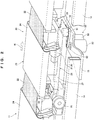
FIG. 2 is a perspective view of a traveling carriage traveling in the sorting facility according to the present invention; and -
FIG. 3 is a block diagram illustrating a control configuration of a traveling carriage traveling in the sorting facility according to the present invention. - Sorting
facility 10 of the present invention will be described. The present invention is not limited to thesorting facility 10 shown as follows. - As illustrated in
FIG. 1 , in thesorting facility 10, a loop-shaped conveyance path K for conveyingarticles 90 are formed. The conveyance path for conveying thearticles 90 is not limited to the loop-shaped conveyance path K. Thesorting facility 10 is mainly composed of amain conveyor device 11 conveying thearticles 90 along the conveyance path K, a plurality ofinduction conveyors 12 inputting thearticles 90 onto the conveyance path K of themain conveyor device 11, a plurality ofchutes 13 receiving thearticles 90 delivered from the conveyance path K of themain conveyor device 11, and anarticle detection device 55 detecting a placement location of thearticle 90 on abelt conveyor 23. - In the
sorting facility 10, thearticle 90 is inputted to the travelingcarriage 20 traveling along rails 14 (seeFIG. 2 ) of themain conveyor device 11 from apredetermined induction conveyor 12. Thearticle 90 inputted to the travelingcarriage 20 is conveyed along the conveyance path K. Thearticle 90 conveyed by the travelingcarriage 20 is delivered to thechute 13 assigned to each store, and is sorted by store, for example. Thearticle 90 conveyed by the travelingcarriage 20 is adjusted so that a placement location on thebelt conveyor 23 is in a center position of thebelt conveyor 23 based on detection by thearticle detection device 55, before delivered to thechute 13. - The devices (the
main conveyor device 11, theinduction conveyors 12, thechute 13, the article detection device 55) of thesorting facility 10 are connected to a supervisory controller 40 (seeFIG. 3 ) controlling theentire sorting facility 10, and are controlled by thesupervisory controller 40. - In the
main conveyor device 11, thetraveling carriage 20 with thearticle 90 placed thereon travels on the rails 14 (seeFIG. 2 ), and thereby thearticle 90 is conveyed along the conveyance path K. - The
induction conveyor 12 inputs thearticle 90 to thebelt conveyor 23 of the travelingcarriage 20 traveling on the conveyance path K. The plurality of (three inFIG. 1 )induction conveyors 12 are disposed side by side along the conveyance path K. In theinduction conveyors 12, thetraveling carriage 20 where thearticle 90 should be inputted in advance is searched for and determined for each of theinduction conveyors 12. Theinduction conveyor 12 inputs thearticle 90 to thepredetermined traveling carriage 20 determined for each of theinduction conveyors 12. - The
chute 13 receives thearticle 90 delivered from the travelingcarriage 20, and conveys the receivedarticle 90 to different downstream equipment (for example, shipment equipment), directly to a vehicle (for example, a truck), or the like. The plurality of (three inFIG. 1 )chutes 13 are disposed side by side along the conveyance path K. Thechute 13 receives thearticle 90 determined in advance for each of thechutes 13 from thetraveling carriage 20. - The
article detection device 55 is composed of a plurality of sensors provided above themain conveyor device 11, at a conveyance downstream side of theinduction conveyor 12, and at a conveyance upstream side of thechute 13. Thearticle detection device 55 detects the placement location of thearticle 90 placed on thebelt conveyor 23, and transmits a detection result to the supervisory controller 40 (seeFIG. 3 ). Thesupervisory controller 40 calculates a deviation of thearticle 90 placed on thebelt conveyor 23 from the center position of thebelt conveyor 23, based on the detection result from thearticle detection device 55. Thesupervisory controller 40 controls thebelt conveyor 23 so that thebelt conveyor 23 moves thearticle 90 to the center position of thebelt conveyor 23 based on the calculated deviation amount. - Next, the traveling
carriage 20 traveling on the conveyance path K will be described. - As illustrated in
FIGS. 1 and2 , the travelingcarriage 20 receives thearticle 90 inputted from thepredetermined induction conveyor 12. The travelingcarriage 20 conveys the receivedarticle 90 along the conveyance path K and delivers thearticle 90 to thepredetermined chute 13. The travelingcarriage 20 is connected to the travelingcarriages 20 adjacent to one another in the conveyance path K, and travels on therails 14 in a state connected to the adjacent travelingcarriages 20. In other words, the plurality of travelingcarriages 20 connected to one another travel on the conveyance path K. - The traveling
carriage 20 travels by drive of acarriage driving device 50. Thecarriage driving device 50 is a friction drive type driving device. Thecarriage driving device 50 includespinch rollers 51 contacting both side surfaces of afin 26 of the travelingcarriage 20, timingbelts 52 rotating thepinch rollers 51, and drivingmotors 53 driving thepinch rollers 51. Thecarriage driving device 50 is a driving device transmitting motive power to the travelingcarriage 20 by using a frictional force by contact of the pair ofpinch rollers 51. Thecarriage driving device 50 causes the rotating pair ofpinch rollers 51 to contact both the side surfaces of thefin 26 of the travelingcarriage 20. Thecarriage driving device 50 runs the travelingcarriage 20 by thrusting thefin 26 forward by a frictional force by contact of the pair ofpinch rollers 51. A plurality ofcarriage driving devices 50 are provided in predetermined positions of the conveyance path K, and are provided between a pair ofrails 14. Thecarriage driving device 50 is supported by asupport frame 15 fixed to therails 14. As illustrated inFIG. 3 , thecarriage driving device 50 is connected to thesupervisory controller 40, and is controlled by thesupervisory controller 40. - As illustrated in
FIGS. 1 and2 , the travelingcarriage 20 mainly includes abody 21 traveling on therails 14, acover 22 covering a gap from the adjacent travelingcarriage 20, thebelt conveyor 23 where thearticle 90 is placed and supported, and abelt driving device 30 for driving thebelt conveyor 23. - As illustrated in
FIG. 2 , thebody 21 mainly includes awheel 25 for traveling on therails 14, thefin 26 contacting thepinch rollers 51 of thecarriage driving device 50, and aframe 27 supporting components of the travelingcarriage 20. - The
fin 26 is a long plate member extended along a longitudinal direction (a traveling direction H of the traveling carriage 20) of the travelingcarriage 20. Thefin 26 is attached to a lower part of thebody 21. - The
cover 22 is composed of a plate-shaped member closing the gap between the travelingcarriages 20 adjacent to each other in the conveyance path K. Thecover 22 is fixed to a rear side end portion of the traveling carriage 20 (end portion at a rear side to the traveling direction H of the traveling carriage 20). - The
belt conveyor 23 is provided at an upper part of thebody 21. Thebelt conveyor 23 conveys thearticle 90 placed on abelt 24 in a direction horizontally orthogonal to the traveling direction H of the travelingcarriage 20, by thebelt 24 being driven by thebelt driving device 30. When the travelingcarriage 20 reaches apredetermined induction conveyor 12, thebelt 24 is driven by thebelt driving device 30, and thereby thebelt conveyor 23 moves thearticle 90 inputted from theinduction conveyor 12 to an appropriate placement location on thebelt 24. When the travelingcarriage 20 reaches apredetermined chute 13, thebelt 24 is driven by thebelt driving device 30, and thereby thebelt conveyor 23 discharges thearticle 90 placed on thebelt 24 in a direction where thechute 13 is located. When thearticle 90 on thebelt 24 deviates from the appropriate position on thebelt 24 during conveyance of thearticle 90 by the travelingcarriage 20, thebelt 24 is driven by thebelt driving device 30, and thereby thebelt conveyor 23 adjusts the placement location of thearticle 90 to the appropriate position. - As illustrated in
FIGS. 2 and3 , thebelt driving device 30 is mainly composed of abelt driving motor 31 for driving thebelt 24 of thebelt conveyor 23, a power generation motor 32 (an example of a "power generation device") for generating electric power for driving thebelt 24 of thebelt conveyor 23, acapacitor 33 storing electric power generated by thepower generation motor 32, adrive controlling inverter 37 for controlling thebelt driving motor 31, a powergeneration controlling inverter 38 for controlling thepower generation motor 32, and a carriage sideoptical transmission device 39 receiving signals from ground sideoptical transmission devices - The
belt driving motor 31 is composed of, for example, a sensor-less servomotor. Thebelt driving motor 31 is connected to thebelt conveyor 23, and drives thebelt 24 of thebelt conveyor 23. Thebelt driving motor 31 is connected to thedrive controlling inverter 37, and has the number of revolutions controlled by thedrive controlling inverter 37. - The
power generation motor 32 is composed of, for example, a sensor-less servo motor. Thepower generation motor 32 is connected to thewheel 25 of the travelingcarriage 20, and generates electric power by a rotary shaft of thepower generation motor 32 rotating by rotation of thewheel 25. Thepower generation motor 32 is connected to the powergeneration controlling inverter 38, and has required torque controlled by the powergeneration controlling inverter 38. - The
capacitor 33 is connected to thebelt driving motor 31 and thepower generation motor 32 via thedrive controlling inverter 37 and the powergeneration controlling inverter 38, and stores the electric power generated by thepower generation motor 32, and supplies the stored electric power to thebelt driving motor 31. - The
drive controlling inverter 37 is connected to thebelt driving motor 31, and controls the number of revolutions of thebelt driving motor 31. Thedrive controlling inverter 37 is connected to thecapacitor 33, and controls the electric power supplied to thebelt driving motor 31 from thecapacitor 33. - The power
generation controlling inverter 38 is connected to thepower generation motor 32, and controls required torque of thepower generation motor 32. The powergeneration controlling inverter 38 is connected to thecapacitor 33, and controls electric power generated by thepower generation motor 32 and stored in thecapacitor 33. - The carriage side
optical transmission device 39 is fixed to theframe 27 of thebody 21. The carriage sideoptical transmission device 39 receives the signals from the ground sideoptical transmission devices optical transmission device 39 is connected to thedrive controlling inverter 37 and the powergeneration controlling inverter 38, and transmits the signals from the ground sideoptical transmission devices drive controlling inverter 37 and the powergeneration controlling inverter 38. - As illustrated in
FIGS. 1 and3 , traveling of the travelingcarriage 20 and an operation of the belt conveyor 23 (belt driving device 30) are controlled by thesupervisory controller 40 provided on the ground side (independently from the traveling carriage 20) and controlling theentire sorting facility 10. The travelingcarriage 20 is not limited to being directly controlled by thesupervisory controller 40 controlling theentire sorting facility 10, and may be controlled by a lower-order controller than thesupervisory controller 40. - The
supervisory controller 40 is connected to the ground sideoptical transmission devices optical transmission device 39, and makes instructions to the travelingcarriages 20 via the ground sideoptical transmission devices supervisory controller 40 controls the travelingcarriages 20 by optical transmission (wireless). - The ground side optical transmission devices, 41, 42, 43, 44, 45, and 46 are devices performing optical transmission with the carriage side
optical transmission devices 39 provided in the respective travelingcarriages 20. - The ground side
optical transmission devices power generation motor 32 to the powergeneration controlling inverter 38 to the carriage sideoptical transmission device 39. The powergeneration controlling inverter 38 operates thepower generation motor 32 to cause thepower generation motor 32 to start generation of power necessary to drive thebelt conveyor 23, by receiving the instruction signals from the ground sideoptical transmission devices - The ground side
optical transmission devices belt driving motor 31 to thedrive controlling inverter 37 to the carriage sideoptical transmission device 39. Thedrive controlling inverter 37 operates thebelt driving motor 31 in a drive position provided in the predetermined position in the conveyance path K as a position requiring drive of thebelt conveyor 23, and starts driving of thebelt 24 of thebelt conveyor 23, by receiving the instruction signals from the ground sideoptical transmission devices belt conveyor 23 refers to a position for loading thearticle 90 onto thebelt conveyor 23 from the induction conveyor 12 ("loading position", the position contacting the downstream side of theinduction conveyor 12 in the main conveyor device 11), the position for adjusting the placement location of thearticle 90 on thebelt conveyor 23 after the travelingcarriage 20 passes through the article detection device 55 ("adjustment position"), and the position for delivering thearticle 90 on thebelt conveyor 23 to the chute 13 ("delivery position", the position contacting the upstream side of thechute 13 in the main conveyor device 11). - The fourth ground side
optical transmission device 44 transmits an instruction signal for driving thebelt conveyor 23 when receiving thearticle 90 inputted from theinduction conveyor 12 on thebelt conveyor 23 of the travelingcarriage 20. Thedrive controlling inverter 37 operates thebelt driving motor 31 in the loading position by receiving the instruction signal from the ground sideoptical transmission device 44. - The fifth ground side
optical transmission device 45 transmits an instruction signal for driving thebelt conveyor 23 when adjusting the placement location of thearticle 90 on thebelt conveyor 23 based on the detection result from thearticle detection device 55. Thedrive controlling inverter 37 operates thebelt driving motor 31 in the adjustment position by receiving the instruction signal from the ground sideoptical transmission device 45. - The sixth ground side
optical transmission device 46 transmits an instruction signal for driving thebelt conveyor 23 when delivering thearticle 90 on thebelt conveyor 23 to thechute 13. Thedrive controlling inverter 37 operates thebelt driving motor 31 in the delivery position by receiving the instruction signal from the ground sideoptical transmission device 46. - The ground side
optical transmission devices - Specifically, the first ground side
optical transmission device 41 is provided at a conveyance upstream side from a position where theinduction conveyor 12 at a most upstream side of the conveyance path K is disposed out of the threeinduction conveyors 12. In other words, the first ground sideoptical transmission device 41 is provided at a conveyance upstream side from the loading position (driving position). - The second ground side
optical transmission device 42 is provided at a conveyance downstream side from a position where theinduction conveyor 12 at a most downstream side of the conveyance path K out of the threeinduction conveyors 12 is disposed, and at a conveyance upstream side from the position where thearticle detection device 55 is disposed. In other words, the second ground sideoptical transmission device 42 is provided at a position at a conveyance upstream side from the adjustment position (driving position). - The third ground side
optical transmission device 43 is provided at a conveyance downstream side from the position where thearticle detection device 55 is disposed, and at a conveyance upstream side from a position where thechute 13 at a most upstream side of the conveyance path K out of the threechutes 13 is disposed. In other words, the third ground sideoptical transmission device 43 is provided at a position at a conveyance upstream side from the delivery position (driving position). - The fourth ground side
optical transmission device 44 is provided at a conveyance upstream side from the position where theinduction conveyor 12 at the most upstream side of the conveyance path K out of the threeinduction conveyors 12 is disposed, and at a conveyance downstream side from a position where the first ground sideoptical transmission device 41 is disposed. - The fifth ground side
optical transmission device 45 is provided at a conveyance downstream side from the position where thearticle detection device 55 is disposed, and at a conveyance upstream side from a position where the third ground sideoptical transmission device 43 is disposed. - The sixth ground side
optical transmission device 46 is provided at a conveyance downstream side from a position where the third ground sideoptical transmission device 43 is disposed, and at a conveyance upstream side from the position where thechute 13 at the most upstream side of the conveyance path K out of the threechutes 13 is disposed. - The first ground side
optical transmission device 41 is provided at a conveyance upstream side from a position where the fourth ground sideoptical transmission device 44 is disposed. The second ground sideoptical transmission device 42 is provided at a conveyance upstream side from a position where the fifth ground sideoptical transmission device 45 is disposed. The third ground sideoptical transmission device 43 is provided at a conveyance upstream side from a position where the sixth ground sideoptical transmission device 46 is disposed. - An interval between the first ground side
optical transmission device 41 and the fourth ground sideoptical transmission device 44, an interval between the second ground sideoptical transmission device 42 and the fifth ground sideoptical transmission device 45, and an interval between the third ground sideoptical transmission device 43 and the sixth ground sideoptical transmission device 46 are set at such distances that thepower generation motor 32 can complete generation of electric power necessary to drive thebelt conveyor 23 by the time when the travelingcarriage 20 reaches the ground sideoptical transmission devices optical transmission devices optical transmission device 41 and the fourth ground sideoptical transmission device 44, the interval between the second ground sideoptical transmission device 42 and the fifth ground sideoptical transmission device 45, and the interval between the third ground sideoptical transmission device 43 and the sixth ground sideoptical transmission device 46 are set based on a conveyance speed of the traveling carriage 20 (conveyance capacity of the main conveyor device 11), a power generation capacity of thepower generation motor 32, a drive capacity of thebelt driving motor 31 and the like. - The ground side
optical transmission devices supervisory controller 40 to the carriage sideoptical transmission device 39 when the travelingcarriage 20 passes. - Next, control of power generation by the
power generation motor 32 of the travelingcarriage 20 will be described. - The traveling
carriage 20 travels by drive of thecarriage driving device 50. Specifically, thebody 21 is thrusted forward by passing thefin 26 of the travelingcarriage 20 between the pair ofpinch rollers 51 rotating by drive of the drivingmotor 53 of thecarriage driving device 50 and thrusting thefin 26 forward. Thereby, thewheel 25 supported by thebody 21 rotates, and the travelingcarriage 20 travels. In other words, by drive of the drivingmotor 53 of thecarriage driving device 50, thewheel 25 is indirectly rotated. - The
power generation motor 32 generates electric power necessary to drive thebelt conveyor 23 by the travelingcarriage 20 traveling on the conveyance path K. Specifically, thepower generation motor 32 is driven by thewheel 25 of the travelingcarriage 20 rotating for the travelingcarriage 20 to travel, and generates the necessary power to drive thebelt conveyor 23. In other words, thepower generation motor 32 is driven by thewheel 25 being indirectly rotated by drive of the drivingmotor 53 of thecarriage driving device 50. That is to say, the driving force of the drivingmotor 53 is distributed to traveling of the travelingcarriage 20 and power generation of thepower generation motor 32. - Here, in the
sorting facility 10, all the travelingcarriages 20 in thesorting facility 10 stop traveling after all sorting operations in the equipment are finished, or due to a power failure or the like in the equipment. When sorting operations in the equipment are started, or after the power failure in the equipment is restored, all the travelingcarriages 20 stopping in thesorting facility 10 are simultaneously actuated. At this time, all the travelingcarriages 20 in thesorting facility 10 travel by the driving force of the drivingmotor 53. When thewheels 25 rotate following traveling of the travelingcarriages 20, and thepower generation motors 32 provided in all the travelingcarriages 20 in thesorting facility 10 simultaneously start power generation, the driving forces of the drivingmotors 53 are distributed to traveling of the travelingcarriages 20 and power generation of thepower generation motors 32. Accordingly, excessive load is exerted on the drivingmotors 53 at the time of actuation. Therefore, it is impossible to sufficiently distribute the driving force necessary for traveling of the travelingcarriages 20 to the travelingcarriages 20, and it is impossible to run the travelingcarriages 20 stably. - Thus, when all the traveling
carriages 20 in thesorting facility 10 are simultaneously actuated, the load on the drivingmotors 53 at the time of actuation of the travelingcarriages 20 is reduced by distributing power generation timings of thepower generation motors 32 provided in the respective travelingcarriages 20, in thesorting facility 10. - Specifically, after all the traveling
carriages 20 in thesorting facility 10 are actuated, and traveling speeds are kept constant at a predetermined speed, drive is started in order from thepower generation motor 32 provided in the travelingcarriage 20 that first passes any of the ground sideoptical transmission devices carriages 20 in thesorting facility 10 are actuated, and the traveling speeds are kept constant at a predetermined speed, power generation is started in order from thepower generation motor 32 provided in the travelingcarriage 20 scheduled to pass through theinduction conveyor 12, thearticle detection device 55, or thechute 13 provided at the conveyance downstream side of the ground sideoptical transmission device carriages 20 to travel stably on the conveyance path K, and is a traveling speed set based on degrees of lift of the travelingcarriages 20 during travelling, an interval between the adjacent travelingcarriages 20 and the like. - For example, as illustrated in
FIG. 1 , a travelingcarriage 20a stops at a conveyance upstream side from the position where the first ground sideoptical transmission device 41 is disposed before actuation of all the travelingcarriages 20 in thesorting facility 10. When the travelingcarriage 20a passes the position where the first ground sideoptical transmission device 41 is disposed after all the travelingcarriages 20 in thesorting facility 10 are actuated and the traveling speeds of all the travelingcarriages 20 in thesorting facility 10 are kept constant at the predetermined speed, the carriage sideoptical transmission device 39 provided in the travelingcarriage 20a receives an instruction signal to operate thepower generation motor 32 from the first ground sideoptical transmission device 41. Thepower generation motor 32 provided in the travelingcarriage 20a starts drive based on the instruction signal, and starts generation of electric power necessary to drive thebelt conveyor 23. Similarly, a travelingcarriage 20b following (at the conveyance upstream side) the travelingcarriage 20a passes the position where the first ground sideoptical transmission device 41 is disposed after all the travelingcarriages 20 in thesorting facility 10 are actuated and the traveling speeds of all the travelingcarriages 20 in thesorting facility 10 are kept constant at the predetermined speed, thepower generation motor 32 provided in the travelingcarriage 20b starts drive, and starts generation of electric power necessary to drive thebelt conveyor 23. As the travelingcarriages optical transmission device 44 is disposed, the carriage sideoptical transmission devices 39 provided in the travelingcarriages belt driving motors 31 from the fourth ground sideoptical transmission device 44. The belt conveyors 23 provided in the travelingcarriages belts 24 of thebelt conveyors 23 to receive thearticles 90 from theinduction conveyor 12. - Similarly, as illustrated in
Fig. 1 , a travelingcarriage 20c stops at a conveyance upstream side from the position where the second ground sideoptical transmission device 42 is disposed before actuation of all the travelingcarriages 20 in thesorting facility 10. When the travelingcarriage 20c passes the position where the second ground sideoptical transmission device 42 is disposed after all the travelingcarriages 20 in thesorting facility 10 are actuated and the traveling speeds of all the travelingcarriages 20 in thesorting facility 10 are kept constant at the predetermined speed, the carriage sideoptical transmission device 39 provided in the travelingcarriage 20c receives an instruction signal to operate thepower generation motor 32 from the second ground sideoptical transmission device 42. Thepower generation motor 32 provided in the travelingcarriage 20c starts power generation based on the instruction signal. Similarly, when a travelingcarriage 20d following the travelingcarriage 20c passes the position where the second ground sideoptical transmission device 42 is disposed after all the travelingcarriages 20 in thesorting facility 10 are actuated and the traveling speeds of all the travelingcarriages 20 in thesorting facility 10 are kept constant at the predetermined speed, thepower generation motor 32 provided in the travelingcarriage 20d starts power generation. As the travelingcarriages optical transmission device 45 is disposed, the carriage sideoptical transmission devices 39 provided in the travelingcarriages belt driving motors 31 from the fifth ground sideoptical transmission device 45. Based on the instruction signals, thebelt conveyors 23 provided in the travelingcarriages belts 24 of thebelt conveyors 23, and thereby adjust the placement locations of thearticles 90 on thebelt conveyors 23. - Similarly, as illustrated in
Fig. 1 , a travelingcarriage 20e stops at a conveyance upstream side from the position where the third ground sideoptical transmission device 43 is disposed before actuation of all the travelingcarriages 20 in thesorting facility 10. When the travelingcarriage 20e passes the position where the third ground sideoptical transmission device 43 is disposed after all the travelingcarriages 20 in thesorting facility 10 are actuated and the traveling speeds of all the travelingcarriages 20 in thesorting facility 10 are kept constant at the predetermined speed, the carriage sideoptical transmission device 39 provided in the travelingcarriage 20e receives an instruction signal to operate thepower generation motor 32 from the third ground sideoptical transmission device 43. Thepower generation motor 32 provided in the travelingcarriage 20e starts power generation based on the instruction signal. Similarly, when a travelingcarriage 20f following the travelingcarriage 20e passes the position where the third ground sideoptical transmission device 43 is disposed after all the travelingcarriages 20 in thesorting facility 10 are actuated and the traveling speeds of all the travelingcarriages 20 in thesorting facility 10 are kept constant at the predetermined speed, thepower generation motor 32 provided in the travelingcarriage 20f starts power generation. As the travelingcarriages optical transmission device 46 is disposed, the carriage sideoptical transmission devices 39 provided in the travelingcarriages belt driving motors 31 from the sixth ground sideoptical transmission device 46. Based on the instruction signals, thebelt conveyors 23 provided in the travelingcarriages belts 24 of thebelt conveyors 23, and thereby deliver thearticles 90 on thebelt conveyors 23 to thechute 13. - As described thus far, according to the present embodiment, generation of the electric power necessary to drive the
belt conveyor 23 is started in order from thepower generation motor 32 provided in the travelingcarriage 20 scheduled to firstly pass the position (driving position) requiring drive of thebelt conveyor 23 on the travelingcarriage 20 after all the travelingcarriages 20 in thesorting facility 10 are actuated and the traveling speed is kept constant at the predetermined speed, and therefore, it is possible to distribute the power generation timings of thepower generation motors 32 at the time of actuation of the travelingcarriages 20. As a result, at the time of the actuation of the travelingcarriages 20, thepower generation motors 32 provided in all the travelingcarriages 20 traveling on the conveyance path K do not start power generation to drive thebelt conveyors 23 simultaneously, and it is possible to reduce load on the drivingmotors 53 for running the travelingcarriages 20. Accordingly, it is possible to sufficiently distribute the driving force of the drivingmotors 53 to traveling of the travelingcarriages 20, and it is possible to stably run the travelingcarriages 20 at the time of actuation of the travelingcarriages 20. Further, it is possible to shorten a time period until the travelingcarriages 20 stably travel at the predetermined conveyance speed after the travelingcarriages 20 are actuated. - In the present embodiment, power generation is started in order from the
power generation motor 32 provided in the travelingcarriage 20 firstly passing any of the ground sideoptical transmission devices carriages 20 in thesorting facility 10 are actuated and the traveling speeds are kept constant at the predetermined speed. However, the present invention is not limited to this, and power generation may be started, for example, in order from thepower generation motor 32 provided in the travelingcarriage 20 passing any of the ground sideoptical transmission devices carriages 20 in thesorting facility 10 are actuated and the travelingcarriages 20 travel a predetermined distance, or after all the travelingcarriages 20 in thesorting facility 10 are actuated and the travelingcarriages 20 travel for a predetermined time period. Here, the predetermined distance refers to a traveling distance of the travelingcarriages 20 required until the traveling speeds of all the travelingcarriages 20 in thesorting facility 10 are kept constant at the predetermined speed after all the travelingcarriages 20 in thesorting facility 10 are actuated. The predetermined time period refers to a traveling time period of the travelingcarriage 20 required until the traveling speeds of all the travelingcarriages 20 in thesorting facility 10 are kept constant at the predetermined speed after all the travelingcarriages 20 in thesorting facility 10 are actuated. In this case, start of power generation of thepower generation motor 32 is controlled by a controller loaded on the travelingcarriage 20. - In the present embodiment, the
carriage driving device 50 for running the travelingcarriage 20 is composed of a friction drive type driving device. However, thecarriage driving device 50 is not limited to this, and may be composed of, for example, a linear motor type driving device. Further, a driving device loaded on the travelingcarriage 20 may run the travelingcarriage 20. -
- 10
- Sorting facility
- 20
- Traveling carriage
- 23
- Belt conveyor
- 32
- Power generation motor (power generation device)
- 90
- Article
- K
- Conveyance path
Claims (4)
- Sorting facility sorting an article by a belt conveyor provided on a traveling carriage traveling along a conveyance path, wherein
a plurality of the traveling carriages travel on the conveyance path,
each of the plurality of the traveling carriages is provided with a power generation device generating electric power by traveling of the traveling carriage,
the belt conveyor provided on each of the plurality of the traveling carriages is driven in a driving position provided in a predetermined position on the conveyance path by the electric power generated by the power generation device, and
the power generation device provided in each of the plurality of the traveling carriages starts generation of electric power necessary to drive the belt conveyor in order from the power generation device provided in the traveling carriage scheduled to pass the driving position first after the plurality of the traveling carriages are actuated and traveling speeds of the plurality of the traveling carriages are kept constant at a predetermined speed. - The sorting facility according to claim 1, wherein
the power generation device starts generation of the electric power necessary to drive the belt conveyor by the traveling carriage provided with the power generation device traveling to a position at an upstream side from the driving position after the plurality of the traveling carriages are actuated and the traveling speeds are kept constant at the predetermined speed. - The sorting facility according to claim 1 or claim 2, wherein
a ground side communication device communicable with the power generation device is provided in a position at an upstream side from the driving position, and
the power generation device starts generation of the electric power necessary to drive the belt conveyor by the traveling carriage provided with the power generation device traveling to the position at the upstream side from the driving position and receiving a signal from the ground side communication device after the plurality of traveling carriages are actuated and the traveling speeds are kept constant at the predetermined speed. - The sorting facility according to any one of claim 1 to claim 3, wherein
the driving position is any of a loading position for loading an article onto the belt conveyor, an adjustment position being a position at a downstream side from the loading position and for adjusting a placement location of the article on the belt conveyor, and a delivery position being a position at a downstream side from the adjustment position and for delivering the article on the belt conveyor.
Applications Claiming Priority (1)
| Application Number | Priority Date | Filing Date | Title |
|---|---|---|---|
| JP2020001108A JP7276163B2 (en) | 2020-01-08 | 2020-01-08 | Sorting equipment |
Publications (2)
| Publication Number | Publication Date |
|---|---|
| EP3848306A1 true EP3848306A1 (en) | 2021-07-14 |
| EP3848306B1 EP3848306B1 (en) | 2026-04-01 |
Family
ID=74004031
Family Applications (1)
| Application Number | Title | Priority Date | Filing Date |
|---|---|---|---|
| EP20217787.9A Active EP3848306B1 (en) | 2020-01-08 | 2020-12-30 | Method for operating a sorting facility |
Country Status (4)
| Country | Link |
|---|---|
| US (1) | US11794213B2 (en) |
| EP (1) | EP3848306B1 (en) |
| JP (1) | JP7276163B2 (en) |
| CN (1) | CN113086531B (en) |
Families Citing this family (3)
| Publication number | Priority date | Publication date | Assignee | Title |
|---|---|---|---|---|
| CN114138027B (en) * | 2021-11-29 | 2023-11-10 | 创新奇智(上海)科技有限公司 | Method and device for controlling speed, electronic equipment and readable storage medium |
| WO2024111040A1 (en) * | 2022-11-22 | 2024-05-30 | ロジスティード株式会社 | Display system, display method, and program |
| DE102022134280B3 (en) * | 2022-12-21 | 2024-03-07 | Coop Systems GmbH | Sorting conveyors, in particular cross-belt sorters or tilting tray sorters, for transporting and sorting piece goods |
Citations (5)
| Publication number | Priority date | Publication date | Assignee | Title |
|---|---|---|---|---|
| EP1216938A1 (en) * | 2000-12-20 | 2002-06-26 | Sandvik Aktiebolag | Contact free signal transmission to and from the trolleys of a sorting conveyor |
| WO2011107815A1 (en) * | 2010-03-04 | 2011-09-09 | Cinetic Sorting S.P.A. | Sorting machine with electrical alternators in supporting wheels |
| US20170057751A1 (en) * | 2015-09-02 | 2017-03-02 | Kabushiki Kaisha Toshiba | Article sorting apparatus |
| JP2018122985A (en) | 2017-02-02 | 2018-08-09 | 三機工業株式会社 | Rail for classifying conveyor |
| US10526146B1 (en) * | 2018-09-07 | 2020-01-07 | Intelligrated Headquarters, Llc | Material handling system and article transfer |
Family Cites Families (26)
| Publication number | Priority date | Publication date | Assignee | Title |
|---|---|---|---|---|
| US4096936A (en) * | 1969-11-03 | 1978-06-27 | Kosan Crisplant A/S | Selectively controllable unloading arrangement for sorting conveyor constructions |
| JPH0646905Y2 (en) * | 1986-08-29 | 1994-11-30 | ト−ヨ−カネツ株式会社 | High-speed automatic sorting device |
| ATE174306T1 (en) * | 1994-09-06 | 1998-12-15 | Mannesmann Ag | SORTING SYSTEM WITH CROSS BELT |
| GB2300612B (en) * | 1995-04-25 | 1998-09-30 | Crisplant As | Conveyor |
| JP3094845B2 (en) * | 1995-06-08 | 2000-10-03 | 株式会社ダイフク | Sorting equipment |
| AU1503400A (en) * | 1998-12-01 | 2000-06-19 | Crisplant A/S | A conveyor/sorter system, a loading conveyor and a control system for such conveyors |
| EP1353867A2 (en) * | 2001-01-22 | 2003-10-22 | Crisplant A/S | Sorter conveyor |
| DE10127127B4 (en) * | 2001-06-05 | 2004-08-05 | Schaffer & Collegen Gmbh | Conveyor |
| US9102336B2 (en) * | 2002-10-16 | 2015-08-11 | Cross Belt Ip, L.L.C. | Portable bin for sortation system |
| ES2686698T3 (en) * | 2012-07-11 | 2018-10-19 | Dematic Corp. | Cross-tape sorting system and article classification method |
| FR3011537B1 (en) * | 2013-10-08 | 2016-01-01 | Cinetic Sorting S P A | METHOD AND DEVICE FOR BAGGAGE SORTING CAPABLE OF PROCESSING SMALL STABLE PRODUCTS AND IRREGULAR FORMS |
| FR3017315B1 (en) * | 2014-02-11 | 2016-03-04 | Cinetic Sorting S P A | METHOD AND DEVICE FOR DRIVING PARCEL SIEVES FOR PLANTS HAVING HIGH LEVEL CHANGES |
| JP2015157659A (en) | 2014-02-21 | 2015-09-03 | 株式会社東芝 | Article sorting equipment |
| JP2016044056A (en) * | 2014-08-25 | 2016-04-04 | 株式会社東芝 | Article sorting device |
| ITUB20152622A1 (en) * | 2015-07-30 | 2017-01-30 | Selex Es Spa | HYBRID TRANSPORT SYSTEM FOR OBJECTS |
| CN105618384A (en) * | 2016-03-19 | 2016-06-01 | 张高强 | Intelligent Roundabout Belt Sorter |
| CN105905550B (en) * | 2016-06-29 | 2018-10-09 | 杭州康奋威科技股份有限公司 | The automatic sorting conveyer of express parcel |
| FR3063987A1 (en) * | 2017-03-17 | 2018-09-21 | Solystic | SORTING OF OBJECTS WITH A PIVOTING SHUTTER SORTING CONVEYOR |
| CN108946002A (en) * | 2017-05-23 | 2018-12-07 | 深圳创顶峰智能物流设备有限公司 | A kind of goods sorting transport mechanism |
| EP3502019B1 (en) * | 2017-12-19 | 2020-06-10 | Fives Intralogistics S.p.A. Con Socio Unico | Method for controlling sorting machines and sorting machine |
| CN108636815A (en) * | 2018-04-18 | 2018-10-12 | 常熟市百联自动机械有限公司 | The sorting vehicle of sorting line |
| CN108554829B (en) * | 2018-05-22 | 2024-07-19 | 深圳市驭智装备技术有限公司 | Cross belt type logistics sorting system |
| CN110077794A (en) * | 2019-05-21 | 2019-08-02 | 江苏浩智智能科技有限公司 | Straight line halved belt sorter based on industrial CW |
| CN110077793B (en) * | 2019-05-21 | 2021-05-14 | 江苏浩智智能科技有限公司 | Double-layer endless cross-belt sorting mechanism based on grid model control |
| CN110340023A (en) * | 2019-06-26 | 2019-10-18 | 青岛职业技术学院 | A kind of automated sorting system |
| CN110525869B (en) * | 2019-09-29 | 2024-07-16 | 西安邮电大学 | Cross sorting trolley device |
-
2020
- 2020-01-08 JP JP2020001108A patent/JP7276163B2/en active Active
- 2020-12-30 EP EP20217787.9A patent/EP3848306B1/en active Active
-
2021
- 2021-01-06 CN CN202110012073.2A patent/CN113086531B/en active Active
- 2021-01-07 US US17/143,730 patent/US11794213B2/en active Active
Patent Citations (5)
| Publication number | Priority date | Publication date | Assignee | Title |
|---|---|---|---|---|
| EP1216938A1 (en) * | 2000-12-20 | 2002-06-26 | Sandvik Aktiebolag | Contact free signal transmission to and from the trolleys of a sorting conveyor |
| WO2011107815A1 (en) * | 2010-03-04 | 2011-09-09 | Cinetic Sorting S.P.A. | Sorting machine with electrical alternators in supporting wheels |
| US20170057751A1 (en) * | 2015-09-02 | 2017-03-02 | Kabushiki Kaisha Toshiba | Article sorting apparatus |
| JP2018122985A (en) | 2017-02-02 | 2018-08-09 | 三機工業株式会社 | Rail for classifying conveyor |
| US10526146B1 (en) * | 2018-09-07 | 2020-01-07 | Intelligrated Headquarters, Llc | Material handling system and article transfer |
Also Published As
| Publication number | Publication date |
|---|---|
| CN113086531A (en) | 2021-07-09 |
| JP2021109717A (en) | 2021-08-02 |
| US20210205853A1 (en) | 2021-07-08 |
| JP7276163B2 (en) | 2023-05-18 |
| CN113086531B (en) | 2024-10-18 |
| EP3848306B1 (en) | 2026-04-01 |
| US11794213B2 (en) | 2023-10-24 |
Similar Documents
| Publication | Publication Date | Title |
|---|---|---|
| EP3848306B1 (en) | Method for operating a sorting facility | |
| EP3848129B1 (en) | Sorting facility | |
| US9708131B2 (en) | Article sorting apparatus | |
| US5577593A (en) | Carrier conveyor system | |
| US9783370B2 (en) | Article sorting apparatus | |
| EP3093075B1 (en) | Article sorting apparatus | |
| JP2003511322A (en) | High speed guidance system | |
| JP7077975B2 (en) | Goods transport equipment | |
| US6966427B2 (en) | Pallet/skid power roll system | |
| US6874614B2 (en) | Method and apparatus for activating a tipping shell sorter, as well as a tipping conveyor element | |
| EP4011808A1 (en) | Apparatus for moving and grouping flat products | |
| JPH05503045A (en) | Intermittent feed conveyor system | |
| CN113086530B (en) | Article conveying equipment | |
| JPH045610B2 (en) | ||
| JP2509954B2 (en) | High-speed automatic sorting device package transfer method | |
| JPS5911489B2 (en) | Method for adjusting the loading section of an automatic parcel sorting device and device for implementing this method | |
| JP2835991B2 (en) | Article conveying roller and conveying system | |
| EP0846078B1 (en) | Conveyor and converger incorporating a conveyor | |
| JP2010024017A (en) | Device and method for correcting carrier position of article, and facility for sorting article using the same device | |
| US20040197173A1 (en) | Transfer media lift exchange system | |
| JPH0646905Y2 (en) | High-speed automatic sorting device | |
| JP3342048B2 (en) | Equipment for separating laminated articles | |
| JPH0640170Y2 (en) | High-speed automatic sorting device | |
| JPH10120166A (en) | Supply device on transfer machine | |
| JPH10120161A (en) | Delivery conveyor device |
Legal Events
| Date | Code | Title | Description |
|---|---|---|---|
| PUAI | Public reference made under article 153(3) epc to a published international application that has entered the european phase |
Free format text: ORIGINAL CODE: 0009012 |
|
| STAA | Information on the status of an ep patent application or granted ep patent |
Free format text: STATUS: THE APPLICATION HAS BEEN PUBLISHED |
|
| AK | Designated contracting states |
Kind code of ref document: A1 Designated state(s): AL AT BE BG CH CY CZ DE DK EE ES FI FR GB GR HR HU IE IS IT LI LT LU LV MC MK MT NL NO PL PT RO RS SE SI SK SM TR |
|
| STAA | Information on the status of an ep patent application or granted ep patent |
Free format text: STATUS: REQUEST FOR EXAMINATION WAS MADE |
|
| 17P | Request for examination filed |
Effective date: 20220111 |
|
| RBV | Designated contracting states (corrected) |
Designated state(s): AL AT BE BG CH CY CZ DE DK EE ES FI FR GB GR HR HU IE IS IT LI LT LU LV MC MK MT NL NO PL PT RO RS SE SI SK SM TR |
|
| STAA | Information on the status of an ep patent application or granted ep patent |
Free format text: STATUS: EXAMINATION IS IN PROGRESS |
|
| 17Q | First examination report despatched |
Effective date: 20230731 |
|
| GRAP | Despatch of communication of intention to grant a patent |
Free format text: ORIGINAL CODE: EPIDOSNIGR1 |
|
| STAA | Information on the status of an ep patent application or granted ep patent |
Free format text: STATUS: GRANT OF PATENT IS INTENDED |
|
| INTG | Intention to grant announced |
Effective date: 20251027 |
|
| GRAS | Grant fee paid |
Free format text: ORIGINAL CODE: EPIDOSNIGR3 |
|
| GRAA | (expected) grant |
Free format text: ORIGINAL CODE: 0009210 |
|
| STAA | Information on the status of an ep patent application or granted ep patent |
Free format text: STATUS: THE PATENT HAS BEEN GRANTED |
|
| AK | Designated contracting states |
Kind code of ref document: B1 Designated state(s): AL AT BE BG CH CY CZ DE DK EE ES FI FR GB GR HR HU IE IS IT LI LT LU LV MC MK MT NL NO PL PT RO RS SE SI SK SM TR |
|
| REG | Reference to a national code |
Ref country code: CH Ref legal event code: F10 Free format text: ST27 STATUS EVENT CODE: U-0-0-F10-F00 (AS PROVIDED BY THE NATIONAL OFFICE) Effective date: 20260401 Ref country code: GB Ref legal event code: FG4D |
|
| REG | Reference to a national code |
Ref country code: DE Ref legal event code: R096 Ref document number: 602020069528 Country of ref document: DE |
|
| REG | Reference to a national code |
Ref country code: IE Ref legal event code: FG4D |