EP3848276A1 - Child bike seat and method of assembling a child bike seat - Google Patents
Child bike seat and method of assembling a child bike seat Download PDFInfo
- Publication number
- EP3848276A1 EP3848276A1 EP20151147.4A EP20151147A EP3848276A1 EP 3848276 A1 EP3848276 A1 EP 3848276A1 EP 20151147 A EP20151147 A EP 20151147A EP 3848276 A1 EP3848276 A1 EP 3848276A1
- Authority
- EP
- European Patent Office
- Prior art keywords
- seat
- child
- frame part
- seat shell
- support structure
- Prior art date
- Legal status (The legal status is an assumption and is not a legal conclusion. Google has not performed a legal analysis and makes no representation as to the accuracy of the status listed.)
- Granted
Links
- 238000000034 method Methods 0.000 title claims abstract description 21
- 230000008878 coupling Effects 0.000 claims description 54
- 238000010168 coupling process Methods 0.000 claims description 54
- 238000005859 coupling reaction Methods 0.000 claims description 54
- 239000000463 material Substances 0.000 claims description 14
- 230000002787 reinforcement Effects 0.000 claims description 13
- 239000005038 ethylene vinyl acetate Substances 0.000 claims description 5
- 229920001200 poly(ethylene-vinyl acetate) Polymers 0.000 claims description 5
- 230000003014 reinforcing effect Effects 0.000 claims description 4
- DQXBYHZEEUGOBF-UHFFFAOYSA-N but-3-enoic acid;ethene Chemical compound C=C.OC(=O)CC=C DQXBYHZEEUGOBF-UHFFFAOYSA-N 0.000 claims description 3
- 239000002131 composite material Substances 0.000 claims description 3
- 239000002861 polymer material Substances 0.000 claims description 3
- 239000003733 fiber-reinforced composite Substances 0.000 claims description 2
- 239000004033 plastic Substances 0.000 claims description 2
- 229920003023 plastic Polymers 0.000 claims description 2
- 239000007779 soft material Substances 0.000 description 2
- 230000001419 dependent effect Effects 0.000 description 1
- 239000011152 fibreglass Substances 0.000 description 1
- 238000004519 manufacturing process Methods 0.000 description 1
- 230000013011 mating Effects 0.000 description 1
Images


Classifications
-
- B—PERFORMING OPERATIONS; TRANSPORTING
- B62—LAND VEHICLES FOR TRAVELLING OTHERWISE THAN ON RAILS
- B62J—CYCLE SADDLES OR SEATS; AUXILIARY DEVICES OR ACCESSORIES SPECIALLY ADAPTED TO CYCLES AND NOT OTHERWISE PROVIDED FOR, e.g. ARTICLE CARRIERS OR CYCLE PROTECTORS
- B62J1/00—Saddles or other seats for cycles; Arrangement thereof; Component parts
- B62J1/14—Separate pillions
- B62J1/16—Separate pillions for children
Definitions
- the present invention relates to a child bike seat, to a child bike seat mount and to a method of assembling a child bike seat.
- Child bike seats also referred to as bicycle child seats
- Known child bike seats comprise a seat and footrests for accommodating the child.
- the seat is made of a material which is sufficiently rigid to support the child during a bike ride.
- Such known child bike seats are, however, often uncomfortable for the child and manufacturing of such known child bike seats can be inefficient.
- the object of the invention is solved by a child bike seat, a child bike seat mount and a method of assembling a child bike seat according to the independent claims.
- Advantageous further configurations are set out in the dependent claims.
- the child bike seat is or may be configured as a rear child bike seat and/or a front child bike seat.
- the child bike seat may comprise a seat body.
- the seat body may comprise a seat shell for accommodating a child therein.
- the seat shell may be dimensioned for partly surrounding the child accommodated therein.
- the seat body may also comprise a support structure for supporting the seat shell.
- the support structure may be made of a material which is sufficiently rigid to support the child in the seat shell during a bike ride.
- the support structure may be further made of a material which is sufficiently rigid to withstand vibrations that are caused during the bike ride.
- the seat shell itself may be made of a material which is not sufficiently rigid to support the child during a bike ride. Instead, the seat shell may be made of a soft material.
- the support structure and the seat shell may be made of different materials.
- the support structure may comprise two parts.
- the support structure may be a two-component structure, for example a two-component frame.
- the two parts may be separate parts.
- An edge portion of the seat shell may be at least partly sandwiched between the two parts of the support structure for holding the seat shell on the support structure.
- the edge portion may at least partly extend along an outer boundary of the seat shell.
- the at least partly sandwiched edge portion of the seat shell may be at least partly positioned between the two parts of the support structure.
- the support structure and the edge portion may form a three-layered structure with the edge portion in between of two layers of the support structure.
- a clamping force may be exerted or may not be exerted on the edge portion by at least one part of the two parts of the support structure.
- the support structure may cover at least a part of the edge portion.
- the support structure may comprise a frame part for supporting the seat shell.
- the frame part may be a framework comprising at least one material recess.
- the support structure may further comprise a cover part.
- the cover part may at least partly cover the frame part and/or the seat shell.
- the cover part may cover the frame part and/or the seat shell on a rear side of the child bike seat.
- the cover part may cover the frame part partly or entirely on the rear side.
- the seat shell may cover the frame part on a front side of the child bike seat.
- the seat shell may cover the frame part on the front side partly or entirely.
- the seat shell and the cover part may cover the frame part on opposite sides of the child bike seat.
- the frame part may be covered two-sided by the seat shell and the cover part.
- the cover part may be hooked into the frame part, wherein the cover part may comprise a hook and the frame part may comprise an engagement portion for engaging the hook.
- the two parts of the support structure may comprise the frame part for supporting the seat shell and the cover part for at least partly covering the frame part.
- the edge portion of the seat shell may be at least partly sandwiched between the frame part and the cover part.
- the support structure may thus be configured for both supporting a child and holding the seat shell thereon.
- the edge portion of the seat shell is partly wrapped around one part of the two parts of the support structure, for example around the frame part.
- the edge portion may be arranged on at least two opposite sides of the one part of the two parts of the support structure, for example the frame part.
- the edge portion may be arranged on a front side and a rear side of the one part of the two parts of the support structure, for example the frame part.
- the edge portion of the seat shell is at least partly clamped between the two parts of the support structure, for example between the frame part and the cover part, for holding the seat shell on the support structure.
- the edge portion of the seat shell may be at least partly wedged or squeezed between the two parts of the support structure, for example between the frame part and the cover part, for exerting a clamping force on the seat shell that can be necessary for holding the seat shell on the support structure.
- At least one part of the two parts of the support structure at least partially comprises a skeleton-like configuration.
- the skeleton-like configuration may comprise a Y-shaped skeleton portion.
- the skeleton-like configuration may comprise at least one of a X-shaped skeleton portion, a V-shaped skeleton portion and a W-shaped skeleton portion.
- the two parts of the support structure are fixedly coupled to each other by means of a positive locking coupling and/or a screw coupling.
- the positive locking coupling may be a snap-fit coupling or a click on coupling.
- the two parts of the support structure, for example the frame part and the cover part may be snapped, clicked or screwed together.
- the two parts of the support structure for example the frame part and the cover part, may be configured for a mutual tool-free assembly or for a mutual tool assembly, respectively.
- the frame part may comprise at least one mounting hole.
- the cover part may further comprise at least one receiving portion in which a fixation means that may be inserted in a mounting hole may be received.
- the fixation means may be a screw and the receiving portion may be a screw entry that may comprise an internal thread.
- the mounting hole may be arranged such that the inserted fixation means is accessible via an opening that may be provided in the seat shell.
- the fixation means may thus be accessible from the front side of the child bike seat.
- the fixation means may further be covered by the cover part at the rear side of the child bike seat.
- the fixation means may further be countersank or hidden in the seat shell and/or the frame part, wherein the fixation means may not protrude beyond the outer contour of the child bike seat.
- the child bike seat may thus comprise a clean rear design for design and safety reasons.
- the seat shell comprises or is made of a polymer material.
- the polymer material may be or may comprise an ethylene-vinyl acetate material, for example an ethylene-vinyl acetate copolymer (also referred to as EVA).
- EVA ethylene-vinyl acetate copolymer
- at least one part of the two parts of the support structure may comprise or may be made of a plastics material and/or a composite material.
- the composite material may be a fiber reinforced composite material, for example a glass reinforced plastic material.
- the seat shell is held on the support structure in a floating manner.
- the seat shell may comprise a child seating area.
- the child seating area of the seat shell may be spaced apart from the support structure for providing a compensation space between the child seating area and the support structure.
- the compensation space may allow or provide a floating movement of a child sitting on the child seating area.
- the seat shell may comprise arm rest portions.
- the arm rest portions may be integrally formed in said seat shell.
- the arm rest portions may be attached, for example screwed, to the support structure.
- the arm rest portions may be bulged.
- the arm rest portions may protrude from the seat shell, wherein a left arm rest portion may protrude from the left side of the seat shell providing a left arm rest for a left arm of a child when sitting in the child bike seat and wherein a right arm rest portion may protrude from the right side of the seat shell providing a right arm rest for a right arm of a child when sitting in the child bike seat.
- the child bike seat may also comprise a handle for gripping with at least one hand of a child when sitting in the child bike seat or a bracket for additionally securing the child when sitting in the child bike seat.
- the handle or bracket may be a central or lateral handle or bracket.
- the support structure may comprise arm rest protrusions.
- the arm rest protrusions may support the arm rest portions of the seat shell.
- the arm rest protrusions may at least partly protrude into the arm rest portions.
- the arm rest protrusions may be at least partly received in the arm rest portions.
- the support structure may comprise at least one reinforcement element for reinforcing the support structure at least in an edge portion thereof.
- the at least one reinforcement element may be arranged on the frame part.
- the at least one reinforcement element may be or may comprise at least one reinforcement rib.
- the child bike seat may comprise the child bike seat mount.
- the child bike seat mount may be arranged or may be configured to be arranged on the child bike seat.
- the child bike seat mount may be arranged or may be configured to be arranged below the child seating area of the child bike seat.
- the child bike seat mount may be arranged or may be configured to be arranged on a base portion of the support structure of the child bike seat and/or below the child seating area of the child bike seat.
- the base portion may be arranged below the child seating area.
- the child bike seat mount may comprise a coupling portion.
- the coupling portion may be configured to be couplable with at least two different fixation modules for coupling the child bike seat mount to a bike.
- the coupling portion may be recessed in at least one part of the two parts of the support structure, for example in at least one of the frame part and the cover part.
- the coupling portion may comprise at least one sliding portion, for example a guiding track, for slidingly receiving the at least two different fixation modules.
- the coupling portion may comprise at least one fixation means for fixing the at least two different fixation modules to the coupling portion.
- the at least one fixation means may comprise at least one screw for screwing one of the two different fixation modules to the coupling portion.
- a child bike seat mount system may comprise the child bike seat mount and at least one of the at least two different fixation modules.
- the coupling portion of the child bike seat mount may be configured to be couplable with the at least two different fixation modules for coupling the child bike seat mount in two different ways to a bike.
- a child bike seat system may comprise the child bike seat and the child bike seat mount system.
- the at least two different fixation modules comprise a fixation module for coupling the child bike seat to a bike frame of the bike.
- the fixation module for coupling the child bike seat to a bike frame of the bike may be a first fixation module.
- the at least two different fixation modules may comprise a fixation module for coupling the child bike seat to a luggage rack of the bike.
- the fixation module for coupling the child bike seat to a luggage rack of the bike may be a second fixation module.
- Described in a further aspect of the present invention is a method of assembling a child bike seat.
- the child bike seat may be at least partly configured as described with respect to the child bike seat according to the preceding aspect.
- the method may comprise a step of providing a frame part.
- the method may further comprise a step of arranging a seat shell for accommodating a child therein on the frame part.
- the method may further comprise a step of mounting a cover part to the frame part.
- the mounting step may be performed for at least partly covering the frame part and/or the seat shell with the cover part.
- the method may further comprise the step of at least partly covering the frame part and/or the seat shell with a cover part.
- the arranging step may comprise partly wrapping an edge portion of the seat shell around the frame part.
- the edge portion may be a sandwiched edge portion.
- the edge portion may comprise an outer lip that is wrapped around the frame part.
- the mounting step can be performed such that an edge portion of the seat shell is sandwiched between the frame part and the cover part.
- the edge portion may be the partly wrapped edge portion according to the preceding preferable embodiment of the method.
- the mounting step may comprise a mounting of the cover part to the frame part such that an edge portion of the seat shell is sandwiched between the frame part and the cover part.
- the method may further comprise the step of sandwiching an edge portion of the seat shell between the frame part and the cover part.
- the frame part and the cover part may form a support structure on which the seat shell may be held.
- the method may further comprise a step of forming a support structure by means of the frame part and the cover part for holding the seat shell thereon.
- the mounting step may further comprise a step of hooking the cover part into the frame part. Additionally, alternatively or subsequently, the mounting step may further comprise a step of pivoting the cover part onto the frame part.
- the mounting step may comprise a step of establishing a positive locking coupling between the frame part and the cover part.
- This step may comprise a respective establishing of a snap-fit coupling and/or by means of a screw coupling.
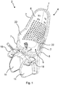
- FIG. 1 shows a rear child bike seat 2.
- the rear child bike seat 2 comprises a seat body 4 for accommodating and supporting a child (not shown) therein when sitting in the rear child bike seat 2.
- the seat body 4 comprises a seat shell 6 made of a soft material that may provide a comfortable seat cushion for the child when sitting in the rear child bike seat 2.
- the seat body 4 further comprises a support structure 8 for supporting the seat shell 6.
- the seat shell 6 has an edge portion 7 that may extend along an outer boundary of the seat body 4 and the support structure 8, respectively.
- the edge portion 7 may be sandwiched between two parts of a support structure 8 for holding the seat shell 6 on the support structure 8. Alternatively or additionally, the edge portion 7 may be partly wrapped around at least one part of the support structure 8 for holding the seat shell 6 on the support structure 8. Hence, the edge portion 7 may be formed as an edge of the seat body 4 surrounding a sitting portion 9 of the rear child bike seat 2.
- the rear child bike seat 2 may further comprise two arm rest portions 22 that may be an integral part of the seat shell 6. Each arm rest portion 22 may protrude outwards. The arm rest portions 22 may be arranged such that the arm rest portions 22 and the sitting portion 9 merge at least partly seamlessly or flush.
- the rear child bike seat 2 may further comprise two separate leg supports 11 each for supporting a leg of the child when sitting in the rear child bike seat 2.
- Each of the leg supports 11 may be attached to the support structure 8.
- the leg supports 11 may further be arranged and/or configured for additionally sandwiching or clamping the edge portion 7 with at least one part of the support structure 8.
- the leg supports 11 may each comprise an adjustable foot support 18 each for providing a footrest for the feet of the child when sitting in the rear child bike seat 2.
- the foot supports 18 may be arranged below the seat shell 6 and are height adjustable.
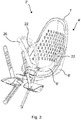
- FIG. 2 shows a front child bike seat 2'.
- the front child bike seat 2' also comprises a seat body 4' for accommodating and supporting a child (not shown) therein when sitting in the front child bike seat 2'.
- the front child bike seat 2' further comprises a support structure 8' for supporting the seat shell 6'.
- the seat body 4' may comprise at least one of the components of the seat body 4 of the rear child bike seat 2 and may be at least partly configured like the seat body 4 of the rear child bike seat 2.
- An edge portion 7' of a seat shell 6' of the seat body 4' may be arranged as described with respect to the rear child bike seat 2.
- the front child bike seat 2' may additionally comprise a central frame portion 26 being arranged so as to be positioned between the child's legs when the child is sitting in the front child bike seat 2'.
- FIG. 3 shows three components of the seat body 4 of the rear child bike seat 2 in an exploded view.
- the seat shell 6 may be a first component of the seat body 4.
- the seat shell 6 may be integrally formed and may be made of an ethylene-vinyl acetate material.
- the seat shell 6 comprising the edge portion 7 may comprise a plurality of holes 10 that may be arranged within the sitting portion 9.
- the support structure 8 may comprise two further components of the seat body 4.
- the support structure 8 may comprise a frame part 12 for supporting the seat shell 6 and a cover part 14.
- the frame part 12 and the cover part 14 may be a second and third component of the seat body 4.
- the cover part 14 may be configured such that it at least partly covers the frame part 12.
- the frame part 12 may comprise at least one reinforcement rib 45, preferably multiple reinforcement ribs 45 arranged along an outer rim or edge of the frame part 12, for reinforcing the frame part 12 in an edge portion thereof.
- the stiffness of the frame part 12 may be increased by further reinforcement ribs 45 including reinforcing ribs that extend in or into the below described arm rest protrusions.
- Some or all of the reinforcement rib or ribs 45 can be arranged substantially perpendicular to the edge of the frame part 12 and/or some or all of the reinforcement ribs may be arranged such that their extension planes extend through a common center point.
- the frame part 12 may further comprise at least one recess 44 for reducing the weight of the child bike seat 2, 2' while not substantially reducing the stiffness of the frame part 12 and the child bike seat.
- the frame part 12 may comprise arm rest protrusions 24 that protrude outwards from an edge portion of the frame part 12.
- the arm rest protrusions 24 may protrude into the arm rest portions 22 of the seat shell 6.
- the arm rest protrusions 24 may at least partially fill the arm rest portions 22 of the seat shell 6, wherein the arm rest portions 22 may accommodate the arm rest protrusions 24.
- the arm rest protrusions 24 may also comprise at least one reinforcement rib for stiffening the arm rest protrusions 24 that might be exposed to loads during a bicycle ride when the child is pulling or pushing the arm rest portions 22 of the seat shell 6.
- the cover part 14 of the support structure 8 may further comprise a child bike seat mount 3.
- the child bike seat mount 3 may be arranged on a base portion of the cover part 14, the support structure 8 and the seat body 4 of the rear child bike seat 2, respectively.
- the child bike seat mount 3 may comprise a coupling portion 5 that is configured to be couplable with at least two different fixation modules for coupling said child bike seat mount 3 to a bike (not shown).
- the child bike seat mount 3 and different fixation modules are described with respect to Figures 5 to 7 .
- the cover part 14 may further comprise a hook 15 for hooking the cover part 14 into the frame part 12 for assembling the seat body 4.
- the cover part 14 may further be configured to cover the outer side of the frame part 12 that is not covered by the seat shell 6 partly or entirely.
- the edge portion 7 of the seat shell 6 may be sandwiched or clamped between the frame part 12 and the cover part 14.
- Figure 4 shows the seat shell 6 and the frame part 12 of the seat body 4 of the rear child bike seat 2.
- the edge portion 7 of the seat shell 6 may be wrapped around the entire outer boundary of the frame part 12 as shown in Figure 4 .
- the edge portion 7 of the seat shell 6 may be partly wrapped around the outer boundary of the frame part 12.
- the edge portion 7 of the seat shell 6 may be wrapped around an upper part of the outer boundary of the frame part 12.
- the edge portion 7 of the seat shell 6 may be wrapped around a lower part of the outer boundary of the frame part 12.
- the edge portion 7 of the seat shell 6 may be wrapped around at least one lateral part, for example a right part and/or a left part of the outer boundary of the frame part 12.
- the frame part 12 may further comprise at least one mounting hole 32 for mounting the cover part 14 to the frame part 12.
- a mounting means for example a screw, for mounting the cover part 14 to the frame part 12 may be inserted and may be accessible via one of the holes 10 of the seat shell 6.
- the frame part 12 and the cover part 14 may be screwed together according an embodiment.
- the frame part 12 may further comprise a hook recess 16 corresponding to the hook 15 arranged on the cover part 14 for hooking the latter to the frame part 12.
- the frame part 12 may comprise a skeleton frame structure with at least one recess 44.
- the frame part 12 may comprise a Y-shaped skeleton portion 13 for stiffening the frame structure of the frame part 12.
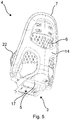
- Figure 5 shows the seat shell 6 and the cover part 14 of the seat body 4 of the rear child bike seat 2.
- the cover part 14 may at least partly cover the frame part 12 from the rear side of the frame part 12.
- the seat shell 6 may further cover the frame part 12 from the front side of the frame part 12.
- the frame part 12 may be sandwiched between the seat shell 6 and the cover part 14.
- the cover part 14 does not comprise a mounting hole for mounting the cover part 14 to the frame part 12 on an exposed rear side of the cover part 14 facing away from the frame part 12.
- the edge portion 7 of the seat shell 6 that may be wrapped around the entire outer boundary of the frame part 12 or that may be partly wrapped around the outer boundary of the frame part 12 may be sandwiched or clamped between the frame part 12 and the cover part 14.
- the cover part 14 may further at least partly cover the wrapped around edge portion 7 of the seat shell 6.
- the coupling portion 5 of the child bike seat mount 3 may comprise a receiving portion 17 for receiving the at least two different fixation modules shown in Figures 6 and 7 .
- the receiving portion 17 may be configured for receiving a coupling portion 5 shown in Figures 6 and 7 of one of the two different fixation modules.
- the receiving portion 17 may comprise at least one female fixation element, for example an internal thread, for receiving at least one male fixation element, for example a screw, wherein the at least two different fixation modules may be fixed to the receiving portion 17 by mating the at least one female fixation element and the at least one male fixation element.
- the receiving portion 17 may comprise a guiding groove or track for slidingly receiving one of the at least two different fixation modules.
- FIG. 6 shows the rear child bike seat 2 with a fixation module 40 for coupling the rear child bike seat 2 to a bike frame (not shown) of the bike.
- the fixation module 40 may be a first fixation module 40.
- the fixation module 40 may comprise a frame clamping element 42 for clamping the rear child bike seat 2 to the bike frame.
- the fixation module 40 may further comprise at least one rod 41 connecting the frame clamping element 42 with a coupling element 43 for coupling the fixation module 40 with the cover part 14 of the rear child bike seat 2.
- the at least one rod 41 may be curved, wherein a curved portion of the rod 41 may be engaged with the coupling element 43.
- the rod 41 may be engaged in an adjustable manner allowing different positions of the frame clamping element 42 relative to the coupling element 43, in particular different positions of the child bike seat 2 in travel direction of the bike.
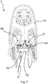
- FIG. 7 shows the rear child bike seat 2 with a fixation module 50 for coupling the rear child bike seat 2 to a luggage rack (not shown) of the bike.
- the fixation module 50 may be a second fixation module 50.
- the fixation module 50 may comprise a coupling element 53 for coupling the fixation module 50 with the cover part 14 of the rear child bike seat 2.
- the coupling elements 43, 53 of both fixation modules 40, 50 as described may substantially comprise the same configuration.
- the rack clamping element 52 for clamping the rear child bike seat 2 to the luggage rack may be arranged on the coupling element 53.
- the rack clamping element 52 may comprise a clamping mechanism 54 for a lateral clamping fixation of the further fixation module 50 to the luggage rack.
- the fixation module 50 may further comprise at least one strap 51 for additionally securing the fixation module 50 when being clamped to the luggage rack.
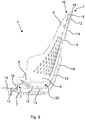
- Figure 8 shows the seat body 4 of the rear child bike seat 2 in a vertical sectional view.
- the seat shell 6 may comprise an outer bulge 19 being wrapped around the frame part 12.
- the cover part 14 may cover the frame part 12 and may be hooked into the frame part 12 by an engagement of the hook 15 in the hooking recess 16 of the frame part 12.
- the seat shell 6 may be spaced from the support structure 8 for providing a compensation space 20 between the seat shell 6 and the support structure 8.
- the compensation space 20 may be provided between a bottom part of the sitting portion 9 of the seat shell 6 and a bottom part of the frame part 12.
- the compensation space 20 allows for a floating support of the child when moving up and down during a bike ride.
- Figure 9 shows the seat body 4' of the front child bike seat 2' in a vertical sectional view.
- the seat shell 6' may comprise an outer bulge 19' being wrapped around the frame part 12'.
- the cover part 14' may cover the frame part 12'.
- the cover part 14' may be screwed to the frame part 12' with a hidden screw 21 which is accessible through an opening of seat shell 6'.
- the seat shell 6' of the front child bike seat 2' may not be spaced apart from the support structure 8 for providing a compensation space 20 between the seat shell 6 and the support structure 8 so that the a bottom part of a sitting portion is supported on the support structure 8.
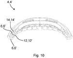
- Figure 10 shows the seat body 4, 4' of the rear child bike seat 2 and the front child bike seat 2' in a horizontal sectional view.
- edge portion 7, 7' of the seat shell 6, 6' of the child bike seat 2, 2' shown in Figures 8 to 10 is sandwiched between the frame part 12, 12' and the cover part 14, 14' in an upper region, a lower region and lateral regions of the seat shell 6, 6'.
- the edge portion 7, 7' of the seat shell 6, 6' of the child bike seat 2, 2' shown in Figures 8 to 10 may additionally be clamped by the frame part 12, 12' and the cover part 14, 14' where a respective sandwiching takes place.
- edge portion 7, 7' of the seat shell 6, 6' of the child bike seat 2, 2' is sandwiched between the frame part 12, 12' and the cover part 14, 14'.
- the edge portions 7, 7' of the seat shells 6, 6' of the child bike seats 2, 2' shown in Figures 8 and 9 may additionally be clamped by the frame part 12, 12' and the cover part 14, 14' where sandwiching takes place.
- the frame part 12 can be provided and then the seat shell 6 may be arranged on the frame part 12 by wrapping the edge portion 7 of the seat shell around the frame part.
- the cover part 14 can be mounted to the frame part 12 such that the edge portion 7 of the seat shell 6 is sandwiched between the frame part 12 and the cover part 14 so that the frame part 12 and the cover part 14 form the support structure 8 on which the seat shell 6 is held.
- the frame part 12 can be provided and then the seat shell 6 may be arranged on the frame part 12 by partly wrapping the edge portion 7 of the seat shell around the frame part.
- the cover part 14 can be mounted to the frame part 12 such that the frame part 12 and/or the seat shell 6 are at least partly covered with the cover part 14.
- the cover part 14 may be mounted to the frame part 12 such that an edge portion 7 of the seat shell 6 is sandwiched between the frame part 12 and the cover part 14, wherein the frame part 12 and the cover part 14 form the support structure 8 on which the seat shell 6 is held.
- the mounting steps may comprise the step of hooking the cover part 14 into the frame part 12, preferably an upper portion of the frame part, and pivoting the cover part 14 onto the frame part 12.
- configurations or embodiments of the present invention may be gained by combining any feature or any combination of features of the rear child bike seat 2 with any other feature or any other combination of features of the front child bike seat 2'.
Landscapes
- Health & Medical Sciences (AREA)
- Child & Adolescent Psychology (AREA)
- General Health & Medical Sciences (AREA)
- Engineering & Computer Science (AREA)
- Mechanical Engineering (AREA)
- Seats For Vehicles (AREA)
Abstract
Description
- The present invention relates to a child bike seat, to a child bike seat mount and to a method of assembling a child bike seat.
- Child bike seats, also referred to as bicycle child seats, are known in the art and exist in different configurations for carrying the child behind or in front of a cyclist. Known child bike seats comprise a seat and footrests for accommodating the child. Typically, the seat is made of a material which is sufficiently rigid to support the child during a bike ride. Such known child bike seats are, however, often uncomfortable for the child and manufacturing of such known child bike seats can be inefficient.
- Accordingly, it is desirable to at least address one of the foregoing and it can be the object of the invention to provide an improved child bike seat and an improved method of assembling a child bike seat.
- In addition, other desirable features and characteristics will become apparent from the subsequent summary and detailed description, and from the appended claims, each taken in conjunction with the accompanying drawings and the background.
- The object of the invention is solved by a child bike seat, a child bike seat mount and a method of assembling a child bike seat according to the independent claims. Advantageous further configurations are set out in the dependent claims.
- Described in an aspect of the present invention is a child bike seat. The child bike seat is or may be configured as a rear child bike seat and/or a front child bike seat. The child bike seat may comprise a seat body. The seat body may comprise a seat shell for accommodating a child therein. The seat shell may be dimensioned for partly surrounding the child accommodated therein.
- The seat body may also comprise a support structure for supporting the seat shell. The support structure may be made of a material which is sufficiently rigid to support the child in the seat shell during a bike ride. The support structure may be further made of a material which is sufficiently rigid to withstand vibrations that are caused during the bike ride. Thus, the seat shell itself may be made of a material which is not sufficiently rigid to support the child during a bike ride. Instead, the seat shell may be made of a soft material. The support structure and the seat shell may be made of different materials.
- According to a preferable configuration, the support structure may comprise two parts. Thus, the support structure may be a two-component structure, for example a two-component frame. The two parts may be separate parts. An edge portion of the seat shell may be at least partly sandwiched between the two parts of the support structure for holding the seat shell on the support structure. The edge portion may at least partly extend along an outer boundary of the seat shell.
- The at least partly sandwiched edge portion of the seat shell may be at least partly positioned between the two parts of the support structure. The support structure and the edge portion may form a three-layered structure with the edge portion in between of two layers of the support structure. A clamping force may be exerted or may not be exerted on the edge portion by at least one part of the two parts of the support structure. The support structure may cover at least a part of the edge portion.
- According to a further preferable configuration, the support structure may comprise a frame part for supporting the seat shell. The frame part may be a framework comprising at least one material recess. The support structure may further comprise a cover part. The cover part may at least partly cover the frame part and/or the seat shell. The cover part may cover the frame part and/or the seat shell on a rear side of the child bike seat. The cover part may cover the frame part partly or entirely on the rear side. The seat shell may cover the frame part on a front side of the child bike seat. The seat shell may cover the frame part on the front side partly or entirely. Hence, the seat shell and the cover part may cover the frame part on opposite sides of the child bike seat. In other words, the frame part may be covered two-sided by the seat shell and the cover part.
- According to an embodiment of the present invention, the cover part may be hooked into the frame part, wherein the cover part may comprise a hook and the frame part may comprise an engagement portion for engaging the hook.
- The two parts of the support structure may comprise the frame part for supporting the seat shell and the cover part for at least partly covering the frame part. The edge portion of the seat shell may be at least partly sandwiched between the frame part and the cover part. The support structure may thus be configured for both supporting a child and holding the seat shell thereon.
- According to an embodiment of the present invention, the edge portion of the seat shell is partly wrapped around one part of the two parts of the support structure, for example around the frame part. The edge portion may be arranged on at least two opposite sides of the one part of the two parts of the support structure, for example the frame part. The edge portion may be arranged on a front side and a rear side of the one part of the two parts of the support structure, for example the frame part.
- According to a further embodiment of the present invention, the edge portion of the seat shell is at least partly clamped between the two parts of the support structure, for example between the frame part and the cover part, for holding the seat shell on the support structure. Thus, the edge portion of the seat shell may be at least partly wedged or squeezed between the two parts of the support structure, for example between the frame part and the cover part, for exerting a clamping force on the seat shell that can be necessary for holding the seat shell on the support structure.
- According to a further embodiment of the present invention, at least one part of the two parts of the support structure, for example the frame part at least partially comprises a skeleton-like configuration. The skeleton-like configuration may comprise a Y-shaped skeleton portion. Alternatively or additionally, the skeleton-like configuration may comprise at least one of a X-shaped skeleton portion, a V-shaped skeleton portion and a W-shaped skeleton portion.
- According to a further embodiment of the present invention, the two parts of the support structure, for example the frame part and the cover part, are fixedly coupled to each other by means of a positive locking coupling and/or a screw coupling. The positive locking coupling may be a snap-fit coupling or a click on coupling. The two parts of the support structure, for example the frame part and the cover part may be snapped, clicked or screwed together. Accordingly, the two parts of the support structure, for example the frame part and the cover part, may be configured for a mutual tool-free assembly or for a mutual tool assembly, respectively.
- The frame part may comprise at least one mounting hole. The cover part may further comprise at least one receiving portion in which a fixation means that may be inserted in a mounting hole may be received. In one example, the fixation means may be a screw and the receiving portion may be a screw entry that may comprise an internal thread. The mounting hole may be arranged such that the inserted fixation means is accessible via an opening that may be provided in the seat shell. The fixation means may thus be accessible from the front side of the child bike seat. The fixation means may further be covered by the cover part at the rear side of the child bike seat. The fixation means may further be countersank or hidden in the seat shell and/or the frame part, wherein the fixation means may not protrude beyond the outer contour of the child bike seat. The child bike seat may thus comprise a clean rear design for design and safety reasons.
- According to a further embodiment of the present invention, the seat shell comprises or is made of a polymer material. The polymer material may be or may comprise an ethylene-vinyl acetate material, for example an ethylene-vinyl acetate copolymer (also referred to as EVA). Alternatively or additionally, at least one part of the two parts of the support structure may comprise or may be made of a plastics material and/or a composite material. The composite material may be a fiber reinforced composite material, for example a glass reinforced plastic material.
- According to a further embodiment of the present invention, the seat shell is held on the support structure in a floating manner. The seat shell may comprise a child seating area. The child seating area of the seat shell may be spaced apart from the support structure for providing a compensation space between the child seating area and the support structure. The compensation space may allow or provide a floating movement of a child sitting on the child seating area.
- According to a further embodiment of the present invention, the seat shell may comprise arm rest portions. The arm rest portions may be integrally formed in said seat shell.
- Alternatively, the arm rest portions may be attached, for example screwed, to the support structure. The arm rest portions may be bulged. The arm rest portions may protrude from the seat shell, wherein a left arm rest portion may protrude from the left side of the seat shell providing a left arm rest for a left arm of a child when sitting in the child bike seat and wherein a right arm rest portion may protrude from the right side of the seat shell providing a right arm rest for a right arm of a child when sitting in the child bike seat. Alternatively or additionally to the arm rest portions, the child bike seat may also comprise a handle for gripping with at least one hand of a child when sitting in the child bike seat or a bracket for additionally securing the child when sitting in the child bike seat. The handle or bracket may be a central or lateral handle or bracket.
- The support structure may comprise arm rest protrusions. The arm rest protrusions may support the arm rest portions of the seat shell. The arm rest protrusions may at least partly protrude into the arm rest portions. The arm rest protrusions may be at least partly received in the arm rest portions.
- According to a further embodiment of the present invention, the support structure may comprise at least one reinforcement element for reinforcing the support structure at least in an edge portion thereof. The at least one reinforcement element may be arranged on the frame part. The at least one reinforcement element may be or may comprise at least one reinforcement rib.
- Described in a further aspect of the present invention is a child bike seat mount. The child bike seat may comprise the child bike seat mount. The child bike seat mount may be arranged or may be configured to be arranged on the child bike seat. The child bike seat mount may be arranged or may be configured to be arranged below the child seating area of the child bike seat. The child bike seat mount may be arranged or may be configured to be arranged on a base portion of the support structure of the child bike seat and/or below the child seating area of the child bike seat. The base portion may be arranged below the child seating area.
- The child bike seat mount may comprise a coupling portion. The coupling portion may be configured to be couplable with at least two different fixation modules for coupling the child bike seat mount to a bike. The coupling portion may be recessed in at least one part of the two parts of the support structure, for example in at least one of the frame part and the cover part.
- According to an embodiment of the present invention, the coupling portion may comprise at least one sliding portion, for example a guiding track, for slidingly receiving the at least two different fixation modules. Alternatively or additionally, the coupling portion may comprise at least one fixation means for fixing the at least two different fixation modules to the coupling portion. The at least one fixation means may comprise at least one screw for screwing one of the two different fixation modules to the coupling portion.
- According to a further aspect, a child bike seat mount system may comprise the child bike seat mount and at least one of the at least two different fixation modules. The coupling portion of the child bike seat mount may be configured to be couplable with the at least two different fixation modules for coupling the child bike seat mount in two different ways to a bike. According to a further aspect, a child bike seat system may comprise the child bike seat and the child bike seat mount system.
- According to a further embodiment of the present invention, the at least two different fixation modules comprise a fixation module for coupling the child bike seat to a bike frame of the bike. The fixation module for coupling the child bike seat to a bike frame of the bike may be a first fixation module. Alternatively or additionally to the fixation module for coupling the child bike seat to a bike frame of the bike, the at least two different fixation modules may comprise a fixation module for coupling the child bike seat to a luggage rack of the bike. The fixation module for coupling the child bike seat to a luggage rack of the bike may be a second fixation module.
- Described in a further aspect of the present invention is a method of assembling a child bike seat. The child bike seat may be at least partly configured as described with respect to the child bike seat according to the preceding aspect. The method may comprise a step of providing a frame part. The method may further comprise a step of arranging a seat shell for accommodating a child therein on the frame part.
- The method may further comprise a step of mounting a cover part to the frame part. The mounting step may be performed for at least partly covering the frame part and/or the seat shell with the cover part. Thus, the method may further comprise the step of at least partly covering the frame part and/or the seat shell with a cover part.
- According to a further preferable embodiment of the method, the arranging step may comprise partly wrapping an edge portion of the seat shell around the frame part. The edge portion may be a sandwiched edge portion. In other words, the edge portion may comprise an outer lip that is wrapped around the frame part.
- According to a further preferable embodiment of the method, the mounting step can be performed such that an edge portion of the seat shell is sandwiched between the frame part and the cover part. The edge portion may be the partly wrapped edge portion according to the preceding preferable embodiment of the method. Hence, the mounting step may comprise a mounting of the cover part to the frame part such that an edge portion of the seat shell is sandwiched between the frame part and the cover part. Thus, the method may further comprise the step of sandwiching an edge portion of the seat shell between the frame part and the cover part. The frame part and the cover part may form a support structure on which the seat shell may be held. Thus, the method may further comprise a step of forming a support structure by means of the frame part and the cover part for holding the seat shell thereon.
- According to a further embodiment of the present invention, the mounting step may further comprise a step of hooking the cover part into the frame part. Additionally, alternatively or subsequently, the mounting step may further comprise a step of pivoting the cover part onto the frame part.
- According to a further embodiment of the present invention, the mounting step may comprise a step of establishing a positive locking coupling between the frame part and the cover part. This step may comprise a respective establishing of a snap-fit coupling and/or by means of a screw coupling.
- Further aspects, configurations or embodiments of the present invention may be gained by combining any feature or any combination of features of at least one aspect, configuration and/or embodiment with any other feature or any other combination of features of at least one other aspect, configuration and/or embodiment. Additional features and advantages may be gleaned by the person skilled in the art from the following description of exemplary embodiments, which are not to be construed as limiting, however, drawing reference to the attached drawings.
- The present invention will hereinafter be described in conjunction with the following drawing figures, wherein like numerals denote like elements, and:
-
Figur 1 shows a rear child bike seat according to an embodiment of the present invention in a perspective view. -
Figur 2 -
Figur 3figure 1 in an exploded view. -
Figur 4figure 1 in a perspective view from behind. -
Figur 5figure 1 with a child bike seat mount according to an embodiment of the invention in a perspective view from behind. -
Figur 6figure 1 in a perspective view from behind with a first fixation module for coupling the rear child bike seat to a bike. -
Figur 7figure 1 in a perspective view from behind with a second fixation module for coupling the rear child bike seat to a bike. -
Figure 8 shows the seat body of the rear child bike seat offigure 1 in a vertical sectional view. -
Figure 9 shows a seat body of the front child bike seat offigure 2 in a vertical sectional view. -
Figure 10 schematically shows the seat body of the rear child bike seat offigure 1 and the front child bike seat offigure 2 in a horizontal sectional view. -
Figure 1 shows a rearchild bike seat 2. The rearchild bike seat 2 comprises aseat body 4 for accommodating and supporting a child (not shown) therein when sitting in the rearchild bike seat 2. Theseat body 4 comprises aseat shell 6 made of a soft material that may provide a comfortable seat cushion for the child when sitting in the rearchild bike seat 2. Theseat body 4 further comprises asupport structure 8 for supporting theseat shell 6. Theseat shell 6 has anedge portion 7 that may extend along an outer boundary of theseat body 4 and thesupport structure 8, respectively. - The
edge portion 7 may be sandwiched between two parts of asupport structure 8 for holding theseat shell 6 on thesupport structure 8. Alternatively or additionally, theedge portion 7 may be partly wrapped around at least one part of thesupport structure 8 for holding theseat shell 6 on thesupport structure 8. Hence, theedge portion 7 may be formed as an edge of theseat body 4 surrounding a sittingportion 9 of the rearchild bike seat 2. - The rear
child bike seat 2 may further comprise twoarm rest portions 22 that may be an integral part of theseat shell 6. Eacharm rest portion 22 may protrude outwards. Thearm rest portions 22 may be arranged such that thearm rest portions 22 and the sittingportion 9 merge at least partly seamlessly or flush. - The rear
child bike seat 2 may further comprise two separate leg supports 11 each for supporting a leg of the child when sitting in the rearchild bike seat 2. Each of the leg supports 11 may be attached to thesupport structure 8. The leg supports 11 may further be arranged and/or configured for additionally sandwiching or clamping theedge portion 7 with at least one part of thesupport structure 8. Furthermore, the leg supports 11 may each comprise anadjustable foot support 18 each for providing a footrest for the feet of the child when sitting in the rearchild bike seat 2. The foot supports 18 may be arranged below theseat shell 6 and are height adjustable. -
Figure 2 shows a front child bike seat 2'. The front child bike seat 2' also comprises a seat body 4' for accommodating and supporting a child (not shown) therein when sitting in the front child bike seat 2'. The front child bike seat 2' further comprises a support structure 8' for supporting theseat shell 6'. The seat body 4' may comprise at least one of the components of theseat body 4 of the rearchild bike seat 2 and may be at least partly configured like theseat body 4 of the rearchild bike seat 2. An edge portion 7' of aseat shell 6' of the seat body 4' may be arranged as described with respect to the rearchild bike seat 2. The front child bike seat 2' may additionally comprise acentral frame portion 26 being arranged so as to be positioned between the child's legs when the child is sitting in the front child bike seat 2'. -
Figure 3 shows three components of theseat body 4 of the rearchild bike seat 2 in an exploded view. Theseat shell 6 may be a first component of theseat body 4. Theseat shell 6 may be integrally formed and may be made of an ethylene-vinyl acetate material. Theseat shell 6 comprising theedge portion 7 may comprise a plurality ofholes 10 that may be arranged within the sittingportion 9. - The
support structure 8 may comprise two further components of theseat body 4. Thesupport structure 8 may comprise aframe part 12 for supporting theseat shell 6 and acover part 14. Theframe part 12 and thecover part 14 may be a second and third component of theseat body 4. Thecover part 14 may be configured such that it at least partly covers theframe part 12. - The
frame part 12 may comprise at least onereinforcement rib 45, preferablymultiple reinforcement ribs 45 arranged along an outer rim or edge of theframe part 12, for reinforcing theframe part 12 in an edge portion thereof. The stiffness of theframe part 12 may be increased byfurther reinforcement ribs 45 including reinforcing ribs that extend in or into the below described arm rest protrusions. Some or all of the reinforcement rib orribs 45 can be arranged substantially perpendicular to the edge of theframe part 12 and/or some or all of the reinforcement ribs may be arranged such that their extension planes extend through a common center point. Theframe part 12 may further comprise at least onerecess 44 for reducing the weight of thechild bike seat 2, 2' while not substantially reducing the stiffness of theframe part 12 and the child bike seat. - The
frame part 12 may comprisearm rest protrusions 24 that protrude outwards from an edge portion of theframe part 12. Thearm rest protrusions 24 may protrude into thearm rest portions 22 of theseat shell 6. Hence, thearm rest protrusions 24 may at least partially fill thearm rest portions 22 of theseat shell 6, wherein thearm rest portions 22 may accommodate the arm rest protrusions 24. Thearm rest protrusions 24 may also comprise at least one reinforcement rib for stiffening thearm rest protrusions 24 that might be exposed to loads during a bicycle ride when the child is pulling or pushing thearm rest portions 22 of theseat shell 6. - The
cover part 14 of thesupport structure 8 may further comprise a childbike seat mount 3. The childbike seat mount 3 may be arranged on a base portion of thecover part 14, thesupport structure 8 and theseat body 4 of the rearchild bike seat 2, respectively. The childbike seat mount 3 may comprise acoupling portion 5 that is configured to be couplable with at least two different fixation modules for coupling said childbike seat mount 3 to a bike (not shown). The childbike seat mount 3 and different fixation modules are described with respect toFigures 5 to 7 . - The
cover part 14 may further comprise ahook 15 for hooking thecover part 14 into theframe part 12 for assembling theseat body 4. Thecover part 14 may further be configured to cover the outer side of theframe part 12 that is not covered by theseat shell 6 partly or entirely. Theedge portion 7 of theseat shell 6 may be sandwiched or clamped between theframe part 12 and thecover part 14. -
Figure 4 shows theseat shell 6 and theframe part 12 of theseat body 4 of the rearchild bike seat 2. Theedge portion 7 of theseat shell 6 may be wrapped around the entire outer boundary of theframe part 12 as shown inFigure 4 . Alternatively, theedge portion 7 of theseat shell 6 may be partly wrapped around the outer boundary of theframe part 12. Theedge portion 7 of theseat shell 6 may be wrapped around an upper part of the outer boundary of theframe part 12. Alternatively or additionally, theedge portion 7 of theseat shell 6 may be wrapped around a lower part of the outer boundary of theframe part 12. Alternatively or additionally, theedge portion 7 of theseat shell 6 may be wrapped around at least one lateral part, for example a right part and/or a left part of the outer boundary of theframe part 12. - The
frame part 12 may further comprise at least one mountinghole 32 for mounting thecover part 14 to theframe part 12. A mounting means, for example a screw, for mounting thecover part 14 to theframe part 12 may be inserted and may be accessible via one of theholes 10 of theseat shell 6. Thus, theframe part 12 and thecover part 14 may be screwed together according an embodiment. Theframe part 12 may further comprise ahook recess 16 corresponding to thehook 15 arranged on thecover part 14 for hooking the latter to theframe part 12. - The
frame part 12 may comprise a skeleton frame structure with at least onerecess 44. Theframe part 12 may comprise a Y-shapedskeleton portion 13 for stiffening the frame structure of theframe part 12. -
Figure 5 shows theseat shell 6 and thecover part 14 of theseat body 4 of the rearchild bike seat 2. Thecover part 14 may at least partly cover theframe part 12 from the rear side of theframe part 12. Theseat shell 6 may further cover theframe part 12 from the front side of theframe part 12. Thus, theframe part 12 may be sandwiched between theseat shell 6 and thecover part 14. According to a preferable embodiment, thecover part 14 does not comprise a mounting hole for mounting thecover part 14 to theframe part 12 on an exposed rear side of thecover part 14 facing away from theframe part 12. - The
edge portion 7 of theseat shell 6 that may be wrapped around the entire outer boundary of theframe part 12 or that may be partly wrapped around the outer boundary of theframe part 12 may be sandwiched or clamped between theframe part 12 and thecover part 14. Thecover part 14 may further at least partly cover the wrapped aroundedge portion 7 of theseat shell 6. - The
coupling portion 5 of the childbike seat mount 3 may comprise a receivingportion 17 for receiving the at least two different fixation modules shown inFigures 6 and7 . The receivingportion 17 may be configured for receiving acoupling portion 5 shown inFigures 6 and7 of one of the two different fixation modules. According to an embodiment, the receivingportion 17 may comprise at least one female fixation element, for example an internal thread, for receiving at least one male fixation element, for example a screw, wherein the at least two different fixation modules may be fixed to the receivingportion 17 by mating the at least one female fixation element and the at least one male fixation element. Additionally or alternatively, the receivingportion 17 may comprise a guiding groove or track for slidingly receiving one of the at least two different fixation modules. -
Figure 6 shows the rearchild bike seat 2 with afixation module 40 for coupling the rearchild bike seat 2 to a bike frame (not shown) of the bike. Thefixation module 40 may be afirst fixation module 40. Thefixation module 40 may comprise a frame clamping element 42 for clamping the rearchild bike seat 2 to the bike frame. Thefixation module 40 may further comprise at least onerod 41 connecting the frame clamping element 42 with acoupling element 43 for coupling thefixation module 40 with thecover part 14 of the rearchild bike seat 2. The at least onerod 41 may be curved, wherein a curved portion of therod 41 may be engaged with thecoupling element 43. Therod 41 may be engaged in an adjustable manner allowing different positions of the frame clamping element 42 relative to thecoupling element 43, in particular different positions of thechild bike seat 2 in travel direction of the bike. -
Figure 7 shows the rearchild bike seat 2 with afixation module 50 for coupling the rearchild bike seat 2 to a luggage rack (not shown) of the bike. Thefixation module 50 may be asecond fixation module 50. Thefixation module 50 may comprise acoupling element 53 for coupling thefixation module 50 with thecover part 14 of the rearchild bike seat 2. Thecoupling elements fixation modules rack clamping element 52 for clamping the rearchild bike seat 2 to the luggage rack may be arranged on thecoupling element 53. Therack clamping element 52 may comprise aclamping mechanism 54 for a lateral clamping fixation of thefurther fixation module 50 to the luggage rack. Thefixation module 50 may further comprise at least onestrap 51 for additionally securing thefixation module 50 when being clamped to the luggage rack. -
Figure 8 shows theseat body 4 of the rearchild bike seat 2 in a vertical sectional view. Theseat shell 6 may comprise anouter bulge 19 being wrapped around theframe part 12. Thecover part 14 may cover theframe part 12 and may be hooked into theframe part 12 by an engagement of thehook 15 in the hookingrecess 16 of theframe part 12. - The
seat shell 6 may be spaced from thesupport structure 8 for providing acompensation space 20 between theseat shell 6 and thesupport structure 8. Thecompensation space 20 may be provided between a bottom part of the sittingportion 9 of theseat shell 6 and a bottom part of theframe part 12. Thecompensation space 20 allows for a floating support of the child when moving up and down during a bike ride. -
Figure 9 shows the seat body 4' of the front child bike seat 2' in a vertical sectional view. Theseat shell 6' may comprise an outer bulge 19' being wrapped around the frame part 12'. The cover part 14' may cover the frame part 12'. The cover part 14' may be screwed to the frame part 12' with ahidden screw 21 which is accessible through an opening ofseat shell 6'. - In comparison to the rear
child bike seat 2, theseat shell 6' of the front child bike seat 2' may not be spaced apart from thesupport structure 8 for providing acompensation space 20 between theseat shell 6 and thesupport structure 8 so that the a bottom part of a sitting portion is supported on thesupport structure 8. -
Figure 10 shows theseat body 4, 4' of the rearchild bike seat 2 and the front child bike seat 2' in a horizontal sectional view. - The
edge portion 7, 7' of theseat shell child bike seat 2, 2' shown inFigures 8 to 10 is sandwiched between theframe part 12, 12' and thecover part 14, 14' in an upper region, a lower region and lateral regions of theseat shell edge portion 7, 7' of theseat shell child bike seat 2, 2' shown inFigures 8 to 10 may additionally be clamped by theframe part 12, 12' and thecover part 14, 14' where a respective sandwiching takes place. - The
edge portion 7, 7' of theseat shell child bike seat 2, 2' is sandwiched between theframe part 12, 12' and thecover part 14, 14'. Theedge portions 7, 7' of theseat shells child bike seats 2, 2' shown inFigures 8 and9 may additionally be clamped by theframe part 12, 12' and thecover part 14, 14' where sandwiching takes place. - Possible mounting steps for assembling child bike seats as described above will be described in the following.
- First, the
frame part 12 can be provided and then theseat shell 6 may be arranged on theframe part 12 by wrapping theedge portion 7 of the seat shell around the frame part. After that, thecover part 14 can be mounted to theframe part 12 such that theedge portion 7 of theseat shell 6 is sandwiched between theframe part 12 and thecover part 14 so that theframe part 12 and thecover part 14 form thesupport structure 8 on which theseat shell 6 is held. - Alternatively, the
frame part 12 can be provided and then theseat shell 6 may be arranged on theframe part 12 by partly wrapping theedge portion 7 of the seat shell around the frame part. After that, thecover part 14 can be mounted to theframe part 12 such that theframe part 12 and/or theseat shell 6 are at least partly covered with thecover part 14. Thecover part 14 may be mounted to theframe part 12 such that anedge portion 7 of theseat shell 6 is sandwiched between theframe part 12 and thecover part 14, wherein theframe part 12 and thecover part 14 form thesupport structure 8 on which theseat shell 6 is held. - The mounting steps may comprise the step of hooking the
cover part 14 into theframe part 12, preferably an upper portion of the frame part, and pivoting thecover part 14 onto theframe part 12. After thecover part 14 is arranged on theframe part 12, a positive locking coupling between theframe part 12 and thecover part 14 by means of a snap-fit coupling and/or a screw coupling as shown for example inFigure 9 is established. - Further aspects, configurations or embodiments of the present invention may be gained by combining any feature or any combination of features of the rear
child bike seat 2 with any other feature or any other combination of features of the front child bike seat 2'. -
- 2
- rear child bike seat
- 2'
- front child bike seat
- 3
- child bike seat mount
- 4, 4'
- seat body
- 5
- coupling portion
- 6, 6'
- seat shell
- 7, 7'
- edge portion
- 8, 8'
- support structure
- 9
- sitting portion
- 10
- hole
- 11
- leg support
- 12, 12'
- frame part
- 13
- Y-shaped skeleton portion
- 14, 14'
- cover part
- 15
- hook
- 16
- hook recess
- 17
- receiving portion
- 18
- foot support
- 19, 19'
- outer bulge
- 20
- compensation space
- 21
- hidden screw
- 22
- arm rest portion
- 24
- arm rest protrusion
- 26
- frame portion
- 32
- mounting hole
- 40
- first fixation module
- 41
- rod
- 42
- frame clamping element
- 43, 53
- coupling element
- 44
- recess
- 45
- reinforcement rib
- 50
- second fixation module
- 51
- strap
- 52
- rack clamping element
- 54
- clamping mechanism
Claims (19)
- Child bike seat (2) comprising
a seat body (4) comprising a seat shell (6) for accommodating a child therein and a support structure (8) for supporting said seat shell (6),
said support structure (8) comprising two parts (12, 14), wherein an edge portion (7) of said seat shell (6) is sandwiched, preferably clamped, between said two parts (12, 14) of said support structure (8) for holding said seat shell (6) on said support structure (8). - Child bike seat (2) according to claim 1,
wherein said edge portion (7) of said seat shell (6) is partly wrapped around one part (12) of said two parts (12, 14) of said support structure (8). - Child bike seat (2) according to one of the preceding claims,
said two parts (12, 14) of said support structure (8) comprising a frame part (12) for supporting said seat shell (6) and a cover part (14) for at least partly covering said frame part (12),
wherein said edge portion (7) of said seat shell (6) is sandwiched between said frame part (12) and said cover part (14). - Child bike seat (2) comprising
a seat body (4) comprising a seat shell (6) for accommodating a child therein and a support structure (8) for supporting the seat shell (6),
said support structure (8) comprising a frame part (12) for supporting said seat shell (6) and a cover part (14) at least partly covering said frame part (12) and/or said seat shell (6),
wherein an edge portion (7) of said seat shell (6) is partly wrapped around said frame part (12). - Child bike seat (2) according to one of the preceding claims,
wherein said edge portion (7) of said seat shell (6) is sandwiched, preferably clamped, between said frame part (12) and said cover part (14). - Child bike seat (2) according to one of the preceding claims,
wherein said frame part (12) at least partially comprises a skeleton-like configuration, said skeleton-like configuration preferably comprising a Y-shaped skeleton portion (13). - Child bike seat (2) according to one of the preceding claims,
wherein said two parts (12, 14) are fixedly coupled to each other by means of a positive locking coupling, preferably a snap-fit coupling and/or a screw coupling, wherein
preferably said frame part (12) comprises a mounting hole (32) and said cover part (14) comprises a receiving portion (17) in which a fixation means, preferably a screw, inserted in said mounting hole (32) is received, wherein said mounting hole (32) is preferably arranged such that said inserted fixation means is accessible via an opening provided in said seat shell (6). - Child bike seat (2) according to one of the preceding claims,
wherein said seat shell (6) comprises a polymer material, preferably an ethylene-vinyl acetate material, and/or wherein at least one part of said two parts (12, 14) of said support structure (8) is made of a plastics material or a composite material, preferably a fiber reinforced composite material. - Child bike seat (2) according to one of the preceding claims,
wherein said seat shell (6) is held on said support structure (8) in a floating manner,
wherein preferably a child seating area of said seat shell (6) is spaced apart from said support structure (8) for providing a compensation space (20) between said child seating area and said support structure (8), said compensation space (20) allowing a floating movement of a child sitting on said child seating area. - Child bike seat (2) according to one of the preceding claims,
said seat shell (6) comprising arm rest portions (22), preferably integrally formed in said seat shell (6) and preferably bulged, and
said support structure (8) comprising arm rest protrusions (24) protruding into and being at least partly received in said arm rest portions (22). - Child bike seat (2) according to one of the preceding claims,
said support structure (8) comprising at least one reinforcement element, preferably at least one reinforcement rib (11), for reinforcing said support structure (8) at least in an edge portion thereof. - Child bike seat mount (3), preferably arranged on a base portion of said support structure (8) of the child bike seat (2) according to one of the preceding claims, said child bike seat (2) being preferably configured as a rear child bike seat (2), the child bike seat mount (3) comprising
a coupling portion (5) being configured to be couplable with at least two different fixation modules (40, 50) for coupling said child bike seat mount (3) to a bike. - Child bike seat mount (3) according to claim 12,
said at least two different fixation modules (40, 50) comprising a first fixation module (40) for coupling the child bike seat (2) to a bike frame of said bike and a second fixation module (50) for coupling the child bike seat (2) to a luggage rack of said bike. - Method of assembling a child bike seat (2) comprising the steps of providing a frame part (12),
arranging a seat shell (6) for accommodating a child therein on said frame part (12), mounting a cover part (14) to said frame part (12) such that an edge portion (7) of said seat shell (6) is sandwiched between said frame part (12) and said cover part (14), said frame part (12) and said cover part (14) preferably forming a support structure (8) on which said seat shell (6) is held. - Method according to claim 14,
wherein said arranging step comprises partly wrapping said edge portion (7) of said seat shell (6) around said frame part (12). - Method of assembling a child bike seat (2) comprising the steps of providing a frame part (12),
arranging a seat shell (6) for accommodating a child therein on said frame part (12),
wherein said arranging step comprises partly wrapping an edge portion (7) of said seat shell (6) around said frame part (12), and
mounting a cover part (14) to said frame part (12) for at least partly covering said frame part (12) and/or said seat shell (6) with said cover part (14) - Method according to claim 16,
wherein said mounting step comprises a mounting of said cover part (14) to said frame part (12) such that an edge portion (7) of said seat shell (6) is sandwiched between said frame part (12) and said cover part (14), said frame part (12) and said cover part (14) preferably forming a support structure (8) on which said seat shell (6) is held. - Method according to one of claims 14 to 17, wherein said mounting step further comprises the step of hooking said cover part (14) into said frame part (12) and pivoting said cover part (14) onto said frame part (12).
- Method according to one of claims 14 to 18,
wherein said mounting step comprises the step of establishing a positive locking coupling between said frame part (12) and said cover part (14), preferably by means of a snap-fit coupling and/or a screw coupling.
Priority Applications (4)
| Application Number | Priority Date | Filing Date | Title |
|---|---|---|---|
| EP20151147.4A EP3848276B1 (en) | 2020-01-10 | 2020-01-10 | Child bike seat and method of assembling a child bike seat |
| EP23208450.9A EP4296118A3 (en) | 2020-01-10 | 2020-01-10 | Child bike seat and method of assembling a child bike seat |
| US17/143,834 US11352085B2 (en) | 2020-01-10 | 2021-01-07 | Child bike seat and method of assembling a child bike seat |
| CN202110023192.8A CN113104142B (en) | 2020-01-10 | 2021-01-08 | Child bicycle seat and method of assembling a child bicycle seat |
Applications Claiming Priority (1)
| Application Number | Priority Date | Filing Date | Title |
|---|---|---|---|
| EP20151147.4A EP3848276B1 (en) | 2020-01-10 | 2020-01-10 | Child bike seat and method of assembling a child bike seat |
Related Child Applications (2)
| Application Number | Title | Priority Date | Filing Date |
|---|---|---|---|
| EP23208450.9A Division EP4296118A3 (en) | 2020-01-10 | 2020-01-10 | Child bike seat and method of assembling a child bike seat |
| EP23208450.9A Division-Into EP4296118A3 (en) | 2020-01-10 | 2020-01-10 | Child bike seat and method of assembling a child bike seat |
Publications (3)
| Publication Number | Publication Date |
|---|---|
| EP3848276A1 true EP3848276A1 (en) | 2021-07-14 |
| EP3848276B1 EP3848276B1 (en) | 2024-01-10 |
| EP3848276C0 EP3848276C0 (en) | 2024-01-10 |
Family
ID=69157707
Family Applications (2)
| Application Number | Title | Priority Date | Filing Date |
|---|---|---|---|
| EP20151147.4A Active EP3848276B1 (en) | 2020-01-10 | 2020-01-10 | Child bike seat and method of assembling a child bike seat |
| EP23208450.9A Pending EP4296118A3 (en) | 2020-01-10 | 2020-01-10 | Child bike seat and method of assembling a child bike seat |
Family Applications After (1)
| Application Number | Title | Priority Date | Filing Date |
|---|---|---|---|
| EP23208450.9A Pending EP4296118A3 (en) | 2020-01-10 | 2020-01-10 | Child bike seat and method of assembling a child bike seat |
Country Status (3)
| Country | Link |
|---|---|
| US (1) | US11352085B2 (en) |
| EP (2) | EP3848276B1 (en) |
| CN (1) | CN113104142B (en) |
Families Citing this family (2)
| Publication number | Priority date | Publication date | Assignee | Title |
|---|---|---|---|---|
| US11173817B2 (en) * | 2018-10-03 | 2021-11-16 | Erica Ferrell | Ventilated child car seat system |
| US20230182625A1 (en) * | 2020-05-14 | 2023-06-15 | Bambino Prezioso Switzerland Ag | Carrycot to be detachably mounted on a base being dismountably attached in a vehicle or on a stroller frame |
Citations (3)
| Publication number | Priority date | Publication date | Assignee | Title |
|---|---|---|---|---|
| JP2012153173A (en) * | 2011-01-24 | 2012-08-16 | Panasonic Corp | Seat cover for device of getting child on bicycle |
| EP2801514A1 (en) * | 2013-05-08 | 2014-11-12 | Thule IP AB | A bicycle child seat |
| EP3290312A1 (en) * | 2016-08-30 | 2018-03-07 | Thule Sweden AB | Child bike seat |
Family Cites Families (43)
| Publication number | Priority date | Publication date | Assignee | Title |
|---|---|---|---|---|
| US3596986A (en) | 1970-03-30 | 1971-08-03 | Gen Motors Corp | Baby seat |
| US3934934A (en) | 1974-07-02 | 1976-01-27 | Buckeye International, Inc. | Child car seating apparatus and method for assembling the same |
| US4053091A (en) | 1976-05-28 | 1977-10-11 | Sears, Roebuck And Co. | Combination rear luggage carrier and child seat for bicycle |
| US4440331A (en) * | 1981-12-03 | 1984-04-03 | Schimmels Kristin L | Protective child carrier assembly |
| US4592592A (en) | 1984-10-15 | 1986-06-03 | Peek Jean M | Safety device for bicycle carrier for children |
| US4750783A (en) | 1986-08-20 | 1988-06-14 | Irby Samuel S | Coacting infant/toddler seat/car seat/stroller system |
| US5299818A (en) | 1989-09-29 | 1994-04-05 | Bell Sports, Inc. | Child's bicycle seat and rack assembly |
| DE9307485U1 (en) | 1993-05-17 | 1993-07-15 | Heinz Kettler Gmbh & Co, 4763 Ense, De | |
| US5370441A (en) | 1994-02-03 | 1994-12-06 | Chuang; Shi-Wen | Baby chair for wheeled cycles |
| US5850958A (en) | 1997-01-14 | 1998-12-22 | Belanger; Alain | Cushioning baby chair base for bicycles |
| DE19845730B4 (en) | 1998-10-05 | 2005-02-10 | Audi Ag | cushion support |
| US6679550B2 (en) * | 1998-10-13 | 2004-01-20 | Xsci, Inc. | Child safety seat |
| US6305744B1 (en) | 1999-10-13 | 2001-10-23 | Michel Martin | Ejectable safety seat structure for recreational-type vehicles |
| AUPQ597500A0 (en) | 2000-03-02 | 2000-03-23 | Camatic Pty. Limited | Improved theatre chair |
| CA2300598A1 (en) | 2000-03-14 | 2001-09-14 | Centric Safe Haven Inc. | Bicycle seat with telescopic support bar |
| DE10147934A1 (en) | 2001-09-27 | 2003-04-10 | Gabriele Brassard | Head support pad for small child's bicycle seat behind saddle has detachable cover and top U-shaped cut-out for head of sleeping child |
| US6612645B1 (en) | 2002-06-06 | 2003-09-02 | Sunny Wheel Industrial Co., Ltd. | Baby seat structure for bicycles |
| ATE554968T1 (en) * | 2004-03-13 | 2012-05-15 | Britax Excelsior | SAFETY SEAT |
| US20060267386A1 (en) | 2005-05-31 | 2006-11-30 | Said Nakhla | Juvenile transport product and method |
| US7517011B2 (en) | 2006-06-28 | 2009-04-14 | Adil Aliyevich Aliev | Combination child carrier |
| US7909400B1 (en) | 2007-04-02 | 2011-03-22 | Todd Delaney | Modular child safety seat for vehicles |
| US7673934B2 (en) | 2007-06-26 | 2010-03-09 | Wonderland Nurserygoods Co., Ltd. | Dual purpose high chair |
| JP4912987B2 (en) | 2007-08-30 | 2012-04-11 | ブリヂストンサイクル株式会社 | Child carrying device and motorcycle |
| DE202008005588U1 (en) * | 2008-04-23 | 2008-07-10 | Nüssel, Ewald | Three-level system with automatic locking system for child restraint systems of classes 0+ and 1 |
| US20100013187A1 (en) | 2008-07-17 | 2010-01-21 | Lonnie Rex Oxley | Bicycle Utility Bracket |
| US8251388B2 (en) | 2008-09-04 | 2012-08-28 | Bell Sports, Inc. | Bicycle child seat |
| NL1036383C2 (en) | 2008-12-23 | 2010-06-24 | Gmg B V | BICYCLE CHAIR. |
| TWI395563B (en) * | 2009-09-17 | 2013-05-11 | Kho David Chuanhankho | Baby seat device |
| PL2384959T5 (en) | 2010-05-03 | 2018-06-29 | Polisport Plasticos, S.A. | Mounting assembly for child's bicycle seat |
| ES2390329B1 (en) | 2011-01-18 | 2013-08-20 | Jane, S.A. | PROCEDURE FOR THE MANUFACTURE OF THE BODY OF CARRIER, CAPAZOS-CUNA AND SIMILAR. |
| EP2540599A1 (en) * | 2011-06-28 | 2013-01-02 | Hamax As | Inflatable upholstery for child seat |
| TWI419806B (en) | 2011-09-02 | 2013-12-21 | Sunny Wheel Ind Co Ltd | Bicycle seat headrest structure |
| US8851569B2 (en) | 2011-09-23 | 2014-10-07 | Chang-Hsien Ho | Full-cover and light-weight safety seat for child |
| US10220734B2 (en) * | 2013-03-05 | 2019-03-05 | Pidyon Controls Inc. | Car seat |
| US8911015B2 (en) | 2013-03-05 | 2014-12-16 | Yochanan Cohen | Car seat |
| US9505457B2 (en) | 2013-09-04 | 2016-11-29 | Ritchie James Buttle | Auxiliary child bicycle seat |
| US10631662B2 (en) * | 2013-11-22 | 2020-04-28 | Breanna L Stachowski | Child seat |
| DE202013011093U1 (en) * | 2013-12-07 | 2014-02-11 | Gertjan Meijerink | Child seat attachment to a bicycle which can be used without tools to attach to different bike frame and luggage rack thus the attachment can be moved transversely in the direction of travel under the seat by means of two lateral clamping body adapt to different frame tubes and luggage carrier and support themselves vertically over a Height, length and angle adjustable bridge. |
| JP6343496B2 (en) * | 2014-05-27 | 2018-06-13 | 日本発條株式会社 | Vehicle seat |
| CN204915785U (en) | 2015-07-28 | 2015-12-30 | 宁波川浪实业有限公司 | Infant has a rest pedally |
| US10472014B2 (en) * | 2018-01-12 | 2019-11-12 | Beto Engineering and Marketing Co., Ltd. | Baby seat of bicycle |
| DE102018112408B3 (en) * | 2018-05-24 | 2019-08-29 | Heinze Metall Gmbh | Belt system for a bicycle child seat |
| DE202018002754U1 (en) * | 2018-06-11 | 2018-06-28 | Maik Bähr | Universal weather protection for bicycle child seats |
-
2020
- 2020-01-10 EP EP20151147.4A patent/EP3848276B1/en active Active
- 2020-01-10 EP EP23208450.9A patent/EP4296118A3/en active Pending
-
2021
- 2021-01-07 US US17/143,834 patent/US11352085B2/en active Active
- 2021-01-08 CN CN202110023192.8A patent/CN113104142B/en active Active
Patent Citations (3)
| Publication number | Priority date | Publication date | Assignee | Title |
|---|---|---|---|---|
| JP2012153173A (en) * | 2011-01-24 | 2012-08-16 | Panasonic Corp | Seat cover for device of getting child on bicycle |
| EP2801514A1 (en) * | 2013-05-08 | 2014-11-12 | Thule IP AB | A bicycle child seat |
| EP3290312A1 (en) * | 2016-08-30 | 2018-03-07 | Thule Sweden AB | Child bike seat |
Also Published As
| Publication number | Publication date |
|---|---|
| US11352085B2 (en) | 2022-06-07 |
| EP4296118A3 (en) | 2024-05-01 |
| EP4296118A2 (en) | 2023-12-27 |
| CN113104142B (en) | 2023-10-13 |
| EP3848276B1 (en) | 2024-01-10 |
| CN113104142A (en) | 2021-07-13 |
| EP3848276C0 (en) | 2024-01-10 |
| US20210214032A1 (en) | 2021-07-15 |
Similar Documents
| Publication | Publication Date | Title |
|---|---|---|
| US11352085B2 (en) | Child bike seat and method of assembling a child bike seat | |
| US8668259B2 (en) | Pivoting nose-less bicycle seat | |
| US5048894A (en) | Seat for special vehicle | |
| US10654539B2 (en) | Child bike seat | |
| US20170197533A1 (en) | Vehicle seat | |
| US11603155B2 (en) | Bicycle saddle, saddle pad, and method for producing a bicycle saddle or saddle pad | |
| US8251388B2 (en) | Bicycle child seat | |
| US20030010556A1 (en) | Luggage rack and backrest mounting system | |
| JP2006271622A (en) | Chair | |
| US20080251681A1 (en) | Mounting Assembly For Stable Attachment of a Seat, Particularly a Bicycle Saddle | |
| JP5101224B2 (en) | Children basket and motorcycle | |
| JP3340205B2 (en) | Vehicle seat | |
| KR101399127B1 (en) | The structural units can be attached sheat of folding Chair | |
| CN217706065U (en) | Rear clothes rack and electric vehicle | |
| JP2009106419A (en) | Chair | |
| JP4040744B2 (en) | Chair seat mounting structure | |
| CN212921805U (en) | Rear armrest device of motorcycle | |
| JP7282729B2 (en) | Child seat fixing structure and bicycle with child seat | |
| CN220826603U (en) | Backrest structure | |
| KR200477990Y1 (en) | back of a chair for Motorcycle | |
| JP7096017B2 (en) | Chair | |
| JP2001008785A (en) | Structure of chair, such as seat or backrest | |
| JP2000198475A (en) | Rear occupant seat | |
| JPH08256872A (en) | Seat of chair | |
| JP4238082B2 (en) | Chair |
Legal Events
| Date | Code | Title | Description |
|---|---|---|---|
| PUAI | Public reference made under article 153(3) epc to a published international application that has entered the european phase |
Free format text: ORIGINAL CODE: 0009012 |
|
| STAA | Information on the status of an ep patent application or granted ep patent |
Free format text: STATUS: THE APPLICATION HAS BEEN PUBLISHED |
|
| AK | Designated contracting states |
Kind code of ref document: A1 Designated state(s): AL AT BE BG CH CY CZ DE DK EE ES FI FR GB GR HR HU IE IS IT LI LT LU LV MC MK MT NL NO PL PT RO RS SE SI SK SM TR |
|
| STAA | Information on the status of an ep patent application or granted ep patent |
Free format text: STATUS: REQUEST FOR EXAMINATION WAS MADE |
|
| 17P | Request for examination filed |
Effective date: 20211229 |
|
| RBV | Designated contracting states (corrected) |
Designated state(s): AL AT BE BG CH CY CZ DE DK EE ES FI FR GB GR HR HU IE IS IT LI LT LU LV MC MK MT NL NO PL PT RO RS SE SI SK SM TR |
|
| P01 | Opt-out of the competence of the unified patent court (upc) registered |
Effective date: 20230528 |
|
| GRAP | Despatch of communication of intention to grant a patent |
Free format text: ORIGINAL CODE: EPIDOSNIGR1 |
|
| STAA | Information on the status of an ep patent application or granted ep patent |
Free format text: STATUS: GRANT OF PATENT IS INTENDED |
|
| INTG | Intention to grant announced |
Effective date: 20231013 |
|
| GRAS | Grant fee paid |
Free format text: ORIGINAL CODE: EPIDOSNIGR3 |
|
| GRAA | (expected) grant |
Free format text: ORIGINAL CODE: 0009210 |
|
| STAA | Information on the status of an ep patent application or granted ep patent |
Free format text: STATUS: THE PATENT HAS BEEN GRANTED |
|
| AK | Designated contracting states |
Kind code of ref document: B1 Designated state(s): AL AT BE BG CH CY CZ DE DK EE ES FI FR GB GR HR HU IE IS IT LI LT LU LV MC MK MT NL NO PL PT RO RS SE SI SK SM TR |
|
| REG | Reference to a national code |
Ref country code: GB Ref legal event code: FG4D |
|
| REG | Reference to a national code |
Ref country code: CH Ref legal event code: EP |
|
| REG | Reference to a national code |
Ref country code: DE Ref legal event code: R096 Ref document number: 602020024071 Country of ref document: DE |
|
| REG | Reference to a national code |
Ref country code: IE Ref legal event code: FG4D |
|
| U01 | Request for unitary effect filed |
Effective date: 20240206 |
|
| P04 | Withdrawal of opt-out of the competence of the unified patent court (upc) registered |
Effective date: 20240212 |
|
| U07 | Unitary effect registered |
Designated state(s): AT BE BG DE DK EE FI FR IT LT LU LV MT NL PT SE SI Effective date: 20240214 |
|
| U1N | Appointed representative for the unitary patent procedure changed [after the registration of the unitary effect] |
Representative=s name: WALLENTIN, LARS; SE |
|
| U20 | Renewal fee paid [unitary effect] |
Year of fee payment: 5 Effective date: 20240226 |
|
| PGFP | Annual fee paid to national office [announced via postgrant information from national office to epo] |
Ref country code: GB Payment date: 20240123 Year of fee payment: 5 |