EP3848208A1 - Rad - Google Patents
Rad Download PDFInfo
- Publication number
- EP3848208A1 EP3848208A1 EP20217732.5A EP20217732A EP3848208A1 EP 3848208 A1 EP3848208 A1 EP 3848208A1 EP 20217732 A EP20217732 A EP 20217732A EP 3848208 A1 EP3848208 A1 EP 3848208A1
- Authority
- EP
- European Patent Office
- Prior art keywords
- wheel
- cover
- actuator
- axis
- closed position
- Prior art date
- Legal status (The legal status is an assumption and is not a legal conclusion. Google has not performed a legal analysis and makes no representation as to the accuracy of the status listed.)
- Granted
Links
Images

Classifications
-
- B—PERFORMING OPERATIONS; TRANSPORTING
- B60—VEHICLES IN GENERAL
- B60B—VEHICLE WHEELS; CASTORS; AXLES FOR WHEELS OR CASTORS; INCREASING WHEEL ADHESION
- B60B7/00—Wheel cover discs, rings, or the like, for ornamenting, protecting, venting, or obscuring, wholly or in part, the wheel body, rim, hub, or tyre sidewall, e.g. wheel cover discs, wheel cover discs with cooling fins
- B60B7/04—Wheel cover discs, rings, or the like, for ornamenting, protecting, venting, or obscuring, wholly or in part, the wheel body, rim, hub, or tyre sidewall, e.g. wheel cover discs, wheel cover discs with cooling fins built-up of several main parts
-
- B—PERFORMING OPERATIONS; TRANSPORTING
- B60—VEHICLES IN GENERAL
- B60B—VEHICLE WHEELS; CASTORS; AXLES FOR WHEELS OR CASTORS; INCREASING WHEEL ADHESION
- B60B19/00—Wheels not otherwise provided for or having characteristics specified in one of the subgroups of this group
- B60B19/10—Wheels not otherwise provided for or having characteristics specified in one of the subgroups of this group with cooling fins
-
- B—PERFORMING OPERATIONS; TRANSPORTING
- B60—VEHICLES IN GENERAL
- B60B—VEHICLE WHEELS; CASTORS; AXLES FOR WHEELS OR CASTORS; INCREASING WHEEL ADHESION
- B60B7/00—Wheel cover discs, rings, or the like, for ornamenting, protecting, venting, or obscuring, wholly or in part, the wheel body, rim, hub, or tyre sidewall, e.g. wheel cover discs, wheel cover discs with cooling fins
- B60B7/06—Fastening arrangements therefor
- B60B7/061—Fastening arrangements therefor characterised by the part of the wheels to which the discs, rings or the like are mounted
- B60B7/065—Fastening arrangements therefor characterised by the part of the wheels to which the discs, rings or the like are mounted to the disc
-
- B—PERFORMING OPERATIONS; TRANSPORTING
- B60—VEHICLES IN GENERAL
- B60B—VEHICLE WHEELS; CASTORS; AXLES FOR WHEELS OR CASTORS; INCREASING WHEEL ADHESION
- B60B7/00—Wheel cover discs, rings, or the like, for ornamenting, protecting, venting, or obscuring, wholly or in part, the wheel body, rim, hub, or tyre sidewall, e.g. wheel cover discs, wheel cover discs with cooling fins
- B60B7/20—Wheel cover discs, rings, or the like, for ornamenting, protecting, venting, or obscuring, wholly or in part, the wheel body, rim, hub, or tyre sidewall, e.g. wheel cover discs, wheel cover discs with cooling fins having an element mounted for rotation independently of wheel rotation
-
- B—PERFORMING OPERATIONS; TRANSPORTING
- B60—VEHICLES IN GENERAL
- B60B—VEHICLE WHEELS; CASTORS; AXLES FOR WHEELS OR CASTORS; INCREASING WHEEL ADHESION
- B60B1/00—Spoked wheels; Spokes thereof
- B60B1/06—Wheels with compression spokes
-
- B—PERFORMING OPERATIONS; TRANSPORTING
- B60—VEHICLES IN GENERAL
- B60B—VEHICLE WHEELS; CASTORS; AXLES FOR WHEELS OR CASTORS; INCREASING WHEEL ADHESION
- B60B2900/00—Purpose of invention
- B60B2900/10—Reduction of
- B60B2900/121—Resisting forces
- B60B2900/1216—Resisting forces due to air-drag
-
- B—PERFORMING OPERATIONS; TRANSPORTING
- B60—VEHICLES IN GENERAL
- B60B—VEHICLE WHEELS; CASTORS; AXLES FOR WHEELS OR CASTORS; INCREASING WHEEL ADHESION
- B60B2900/00—Purpose of invention
- B60B2900/50—Improvement of
- B60B2900/513—Cooling, e.g. of brakes
-
- B—PERFORMING OPERATIONS; TRANSPORTING
- B60—VEHICLES IN GENERAL
- B60B—VEHICLE WHEELS; CASTORS; AXLES FOR WHEELS OR CASTORS; INCREASING WHEEL ADHESION
- B60B3/00—Disc wheels, i.e. wheels with load-supporting disc body
- B60B3/002—Disc wheels, i.e. wheels with load-supporting disc body characterised by the shape of the disc
- B60B3/007—Disc wheels, i.e. wheels with load-supporting disc body characterised by the shape of the disc in the intermediate section
-
- B—PERFORMING OPERATIONS; TRANSPORTING
- B60—VEHICLES IN GENERAL
- B60B—VEHICLE WHEELS; CASTORS; AXLES FOR WHEELS OR CASTORS; INCREASING WHEEL ADHESION
- B60B7/00—Wheel cover discs, rings, or the like, for ornamenting, protecting, venting, or obscuring, wholly or in part, the wheel body, rim, hub, or tyre sidewall, e.g. wheel cover discs, wheel cover discs with cooling fins
- B60B7/06—Fastening arrangements therefor
- B60B7/061—Fastening arrangements therefor characterised by the part of the wheels to which the discs, rings or the like are mounted
- B60B7/066—Fastening arrangements therefor characterised by the part of the wheels to which the discs, rings or the like are mounted to the hub
-
- B—PERFORMING OPERATIONS; TRANSPORTING
- B60—VEHICLES IN GENERAL
- B60Y—INDEXING SCHEME RELATING TO ASPECTS CROSS-CUTTING VEHICLE TECHNOLOGY
- B60Y2306/00—Other features of vehicle sub-units
-
- Y—GENERAL TAGGING OF NEW TECHNOLOGICAL DEVELOPMENTS; GENERAL TAGGING OF CROSS-SECTIONAL TECHNOLOGIES SPANNING OVER SEVERAL SECTIONS OF THE IPC; TECHNICAL SUBJECTS COVERED BY FORMER USPC CROSS-REFERENCE ART COLLECTIONS [XRACs] AND DIGESTS
- Y02—TECHNOLOGIES OR APPLICATIONS FOR MITIGATION OR ADAPTATION AGAINST CLIMATE CHANGE
- Y02T—CLIMATE CHANGE MITIGATION TECHNOLOGIES RELATED TO TRANSPORTATION
- Y02T10/00—Road transport of goods or passengers
- Y02T10/80—Technologies aiming to reduce greenhouse gasses emissions common to all road transportation technologies
- Y02T10/88—Optimized components or subsystems, e.g. lighting, actively controlled glasses
Definitions
- the invention relates to a wheel, in particular a light alloy wheel, with at least two wheel spokes, a hub, an electrical energy generator and at least one actuator which is electrically connected to the energy generator, at least one cover being assigned to at least one space between two adjacent wheel spokes, the cover can be moved by the actuator into an open position and into a closed position, the cover at least partially exposing the gap in the open position and the cover at least partially covering the gap in the closed position.
- a generic wheel with several wheel spokes is known, between which spaces are formed.
- the intermediate spaces can be exposed by means of covers arranged on the wheel for cooling a brake of the wheel or covered over to improve the aerodynamic properties of the wheel.
- the covers can be rotated, pivoted or moved in a translatory manner.
- actuators are provided that are electrically connected to an electrical energy generator, the energy generator generating electrical energy from the rotational movement of the wheel.
- the actuators are primarily used to move the covers into the open position.
- spring elements are disclosed as restoring means, which move the covers back into the closed position after the actuators have been switched off.
- the invention is based on the fundamental consideration that a pivoting of the at least one cover about a radially aligned pivot axis of the wheel requires particularly little space, since the gap is used as a movement space for the cover. In a similar way it is the rotation of the actuator around the wheel axle also saves space, the wheel axle being aligned with the direction of extent of the wheel shaft.
- the combination of the two mentioned movements according to the invention results in a structurally significantly simplified and thus more economical wheel.
- the wheel axle is aligned with the wheel shaft, which drives the wheel to rotate and runs through the wheel in a radially centered manner.
- a radially aligned pivot axis is perpendicular to the wheel axis.
- the invention takes into account that at high speeds of a vehicle with the known wheels, great flow resistances (measured as c w value) occur, in particular due to turbulent air flows between the wheel spokes, on the other hand, when braking the vehicle due to brakes arranged on the wheels, air flow around is necessary for cooling .
- the spaces between the wheel spokes are covered by the at least one cover in its closed position in such a way that no significant flow resistance develops.
- the closed position of the at least one cover is therefore particularly suitable for high rotational speeds of the wheel.
- air from the external environment can enter the space.
- the gap is released in such a way that the air from the external environment can, for example, cool the brake of the wheel.
- the projection corresponds to a mechanical impact which fixes the position of the cover in the closed position and which prevents the cover from moving further beyond the closed position.
- the at least one cover is pivoted in the open position such that the cover protrudes from a radial plane of the wheel that is spanned by the cover in the closed position, which is in particular aligned perpendicular to the wheel axis and which are preferably all radially aligned Includes swivel axes.
- the energy generator can be an electromagnetic energy generator arranged in the cylindrical hub of the wheel, by means of which electrical energy can be generated, preferably by induction, in particular when the wheel rotates.
- a rechargeable energy store is preferably connected to the electromagnetic generator and to the actuator in order to supply the actuator with energy even when the wheel is not rotating.
- the energy generator and / or the energy store and / or the actuator are arranged in the cylindrical hub of the wheel in order to obtain a structurally simple structure.
- an antenna for data transmission can be provided, by means of the parameters of the wheel by sensors arranged on the wheel, in particular sensors for measuring the rotational speed of the wheel and / or its acceleration and / or for determining the location and / or condition of the at least one cover, detectable and can be transmitted to a data acquisition device arranged outside the wheel are.
- the antenna is preferably connected to the energy generator and to the actuator, so that the actuator can in particular be remotely controlled by the user.
- the at least one cover can be moved, in particular automatically, into the open position and into the closed position as a function of the rotational speed of the wheel, it also being possible for the movement of the cover to be triggered by a manual input.
- several covers are provided, all of which can be pivoted by the actuator in such a way that all covers can be moved into the open and / or closed position at the same time.
- the cover is preferably connected to the actuator by at least one connecting rod, so that the cover can be moved particularly easily by the actuator.
- the connecting rod serves as a translation between the rotary movement of the actuator about the wheel axis and the pivoting of the cover about the radially aligned pivot axis.
- the invention can provide that the connecting rod is positively connected, in particular in one piece, to the cover.
- the connecting rod can be rotated about its longitudinal axis by the actuator in order to pivot the cover into the open position and / or into the closed position.
- the longitudinal axis of the connecting rod corresponds to the radially aligned pivot axis for pivoting the cover.
- the connecting rod can have a bearing part facing the actuator, which - preferably frictionally - with the Actuator is connected.
- the bearing part of the connecting rod is preferably frustoconical, so that the connecting rod can be rotated about its longitudinal axis by rotating the actuator and serves as a mechanical transmission.
- a cover is preferably assigned to each intermediate space, so that, in particular in the closed position, all the intermediate spaces of the wheel are at least partially covered by a cover. In its closed position, the cover preferably completely covers the intermediate space in order to minimize the air flow into the intermediate space of the wheel.
- several covers are provided and each cover can be pivoted about a radially aligned pivot axis, all pivot axes being aligned perpendicular to the wheel axis. In a further development, at least two pivot axes are aligned with one another.
- Fig. 1 shows a wheel 10 according to the invention, which is designed as a motor vehicle light alloy wheel with a rim 11 made of light metal, a tire 12 being clamped in a rim well 13 of the wheel 10.
- the wheel 10 has five star-shaped and radially aligned wheel spokes 14 which extend from a radially centered hub 15 of the wheel 10 to a radially outer rim flange 16 of the wheel 10 and are usually integral with the remaining wheel components (rim 11 and hub 15) are formed, preferably cast or forged.
- each wheel spoke 14 has a projection 25 on both sides in the circumferential direction.
- an electromagnetic energy generator (not shown) is arranged, which generates electrical energy by means of induction when the wheel 10 rotates about the wheel axis A.
- the wheel axis A corresponds to the direction of extension of a wheel shaft, not shown, which drives the wheel 10 to rotate.
- the energy generator is electrically connected to an actuator 17 which - switchable - is arranged in the cavity 15 a of the hub 15.
- the actuator 17 is in Fig. 2 shown enlarged and arranged on a pivot bearing, not shown, so that the actuator 17 is rotatable about the wheel axis A relative to the wheel spokes 14.
- Fig. 2 shown enlarged and arranged on a pivot bearing, not shown, so that the actuator 17 is rotatable about the wheel axis A relative to the wheel spokes 14.
- a housing 18 of the actuator 17 is shown half-open in order to reveal a view of a frustoconical actuator 19 within the housing 18.
- the actuator 19 is like the actuator 17 as a whole, rotatable about the wheel axis A relative to the wheel spokes 14.
- FIG. 2 shows the wheel 10 of Fig. 1 in an enlarged view, five connecting rods 20 being captively connected to the actuator 17 and for this purpose in FIG Fig. 2 Reach through radial openings, not shown, in the lateral surface of the housing 18.
- the connecting rods 20 have as shown in FIG Fig. 1 each with their longitudinal directions in radially aligned pivot axes R of the wheel 10, all pivot axes R being aligned perpendicular to the wheel axis A.
- the connecting rods 20 are immovable along their longitudinal direction, but can each be rotated about their longitudinal directions.
- the connecting rods 20 each have a frustoconical bearing part 21 on their end faces 20a directed towards the actuator 17, which bearing part 21 rests on a lateral surface 22 of the actuator 19 and can be driven by its rotational movement about the wheel axis A.
- the rotary movement of the actuator 19 can be transmitted to the connecting rods 20, which then rotate about the respective pivot axes R.
- the connecting rods 20 are each connected in one piece to a cover 23 with a base area in the shape of a sector of a circle.
- a total of five covers 23 are provided, each of which is arranged in a space 24 between two adjacent wheel spokes 14.
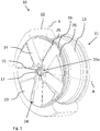
- the covers 23 are in an Fig. 2 closed position shown and one in Fig. 3 Open position shown movable. In the closed position of the covers 23 according to Fig. 2 these are arranged in a radial plane of the wheel 10, which of the covers 23 in the closed position according to Fig. 2 is clamped, which therefore contains the pivot axes R and which is arranged perpendicular to the wheel axis A. All intermediate spaces 24 are covered by the covers 23, the covers 23 resting on the projections 25 of the wheel spokes 14.
- the actuator 19 of the actuator 17 is rotated by electrical energy from the energy generator about the wheel axis A, as a result of the frictional connection of the connecting rods 20 with the actuator 19, all connecting rods 20 rotate simultaneously about their respective longitudinal axes, which with the pivot axes R. align, turn.
- the covers 23 connected to the connecting rods 20 follow the rotational movements of the connecting rods 20 and are pivoted about the pivot axes R assigned to the respective cover 23 in such a way that the covers 23 in their open position of the Fig. 3 protrude from the radial plane of the wheel 10, so that air from the external environment can get into the spaces 24.
- the transition from the closed position of the covers 23 to the open position takes place in the opposite manner.
Landscapes
- Engineering & Computer Science (AREA)
- Mechanical Engineering (AREA)
- Arrangement Or Mounting Of Propulsion Units For Vehicles (AREA)
- Connection Of Motors, Electrical Generators, Mechanical Devices, And The Like (AREA)
Abstract
Description
- Die Erfindung betrifft ein Rad, insbesondere Leichtmetallrad, mit mindestens zwei Radspeichen, einer Nabe, einem elektrischen Energiegenerator und mindestens einem Aktuator, der elektrisch mit dem Energiegenerator verbunden ist, wobei mindestens eine Abdeckung mindestens einem Zwischenraum zwischen zwei benachbarten Radspeichen zugeordnet ist, wobei die Abdeckung durch den Aktuator in eine Offenstellung und in eine Schließstellung bewegbar ist, wobei die Abdeckung in der Offenstellung den Zwischenraum zumindest teilweise freigibt und wobei die Abdeckung in der Schließstellung den Zwischenraum mindestens teilweise überdeckt.
- Aus der
EP 1 319 526 A2 ist ein gattungsgemäßes Rad mit mehreren Radspeichen bekannt, zwischen denen Zwischenräume ausgebildet sind. Die Zwischenräume können mittels am Rad angeordneter Abdeckungen zur Kühlung einer Bremse des Rades freigelegt oder zur Verbesserung der aerodynamischen Eigenschaften des Rades überdeckt werden. Die Abdeckungen können gedreht, verschwenkt oder translatorisch bewegt werden. Zur Bewegung der Abdeckungen sind Aktuatoren vorgesehen, die mit einem elektrischen Energiegenerator elektrisch verbunden sind, wobei der Energiegenerator elektrische Energie aus der Drehbewegung des Rades erzeugt. Die Aktuatoren dienen in erster Linie dazu, die Abdeckungen in die Offenstellung zu bewegen. Zur Bewegung der Abdeckungen in die Schließstellung sind Federelemente als Rückstellmittel offenbart, die nach einem Abschalten der Aktuatoren die Abdeckungen wieder in die Schließstellung bewegen. - Bei den bekannten Rädern ist jeder Abdeckung ein Aktuator zugeordnet, so dass die Steuerung der Bewegungen der Abdeckungen konstruktiv aufwändig und daher teuer ist.
- Es ist daher die Aufgabe der Erfindung, die Nachteile aus dem Stand der Technik zu beseitigen und ein kostengünstigeres und konstruktiv einfacheres Rad zu entwickeln.
- Die Aufgabe wird durch ein Rad mit den Merkmalen von Anspruch 1 gelöst, das erfindungsgemäß dadurch gekennzeichnet ist, dass die Abdeckung um eine der Abdeckung zugeordnete radial verlaufende Schwenkachse des Rades verschwenkbar ist, indem der Aktuator um die Radachse und relativ zu den Radspeichen drehbar ist, wobei die radial verlaufende Schwenkachse senkrecht zur Radachse ausgerichtet ist und dass die Radspeichen mindestens einen Vorsprung in Umfangsrichtung aufweisen, auf dem die Abdeckung in der Schließstellung aufliegt.
- Die Erfindung basiert auf der grundlegenden Überlegung, dass eine Verschwenkung der mindestens einen Abdeckung um eine radial ausgerichtete Schwenkachse des Rades besonders wenig Platz erfordert, da der Zwischenraum als Bewegungsraum für die Abdeckung genutzt wird. In ähnlicher Weise ist die Drehung des Aktuators um die Radachse ebenfalls platzsparend, wobei die Radachse mit der Erstreckungsrichtung der Radwelle fluchtet. Durch die erfindungsgemäße Kombination der beiden genannten Bewegungen ergibt sich ein konstruktiv wesentlich vereinfachtes und damit günstigeres Rad.
- Im Sinne der Erfindung fluchtet die Radachse mit der Radwelle, die das Rad zu Drehbewegungen antreibt und radial zentriert durch das Rad verläuft. Im Sinne eines gedachten zylindrischen Koordinatensystems steht eine radial ausgerichtete Schwenkachse senkrecht zu der Radachse.
- Die Erfindung berücksichtigt, dass bei großen Geschwindigkeiten eines Fahrzeugs bei den bekannten Rädern große Strömungswiderstände (gemessen als cw-Wert) insbesondere durch turbulente Luftströmungen zwischen den Radspeichen auftreten, andererseits beim Bremsen des Fahrzeugs durch an den Rädern angeordnete Bremsen eine Luftumströmung zur Kühlung erforderlich ist. Die Zwischenräume der Radspeichen werden durch die mindestens eine Abdeckung in deren Schließstellung derart überdeckt, dass sich kein nennenswerter Strömungswiderstand ausbildet. Die Schließstellung der mindestens einen Abdeckung eignet sich daher insbesondere für große Drehgeschwindigkeiten des Rades. In der Offenstellung der Abdeckung kann Luft aus der äußeren Umgebung in den Zwischenraum gelangen. Der Zwischenraum ist derart freigegeben, dass durch die Luft aus der äußeren Umgebung beispielsweise die Bremse des Rades gekühlt werden kann. Während bei hohen Drehgeschwindigkeiten eines Rades dessen Kontur ohnehin nicht sichtbar ist, wird so bei geringen Geschwindigkeiten und Stillstand das Reifendesign sichtbar. Der Vorsprung entspricht im Sinne der Erfindung einem mechanischen Aufschlag, der die Position der Abdeckung in der Schließstellung festlegt und der ein Weiterbewegen der Abdeckung über die Schließstellung hinaus verhindert.
- Weiterhin kann vorgesehen sein, dass die mindestens eine Abdeckung in der Offenstellung derart verschwenkt ist, dass die Abdeckung aus einer Radialebene des Rades heraus ragt, die von der Abdeckung in Schließstellung aufgespannt wird, die insbesondere senkrecht zur Radachse ausgerichtet ist und die vorzugsweise sämtliche radial ausgerichteten Schwenkachsen enthält.
- Der Energiegenerator kann ein in der zylindrischen Nabe des Rades angeordneter elektromagnetischer Energiegenerator sein, mittels dessen insbesondere bei einer Drehbewegung des Rades elektrische Energie vorzugsweise durch Induktion erzeugbar ist. Vorzugsweise ist ein wiederaufladbarer Energiespeicher mit dem elektromagnetischen Generator und mit dem Aktuator verbunden, um den Aktuator auch dann mit Energie zu versorgen, wenn sich das Rad nicht dreht. Höchst vorzugsweise sind der Energiegenerator und/oder der Energiespeicher und/oder der Aktuator in der zylindrischen Nabe des Rades angeordnet, um einen konstruktiv einfachen Aufbau zu erhalten.
- Ferner kann eine Antenne zur Datenübertragung vorgesehen sein, mittels der Parameter des Rades durch am Rad angeordnete Sensoren, insbesondere Sensoren zur Messung der Drehgeschwindigkeit des Rades und/oder dessen Beschleunigung und/oder zur Orts- und/oder Zustandsbestimmung der mindestens einen Abdeckung, erfassbar und an eine außerhalb des Rades angeordnete Datenerfassungseinrichtung übermittelbar sind. Vorzugsweise ist die Antenne mit dem Energiegenerator und mit dem Aktuator verbunden, so dass der Aktuator insbesondere durch den Benutzer fernsteuerbar ist. Weiter vorzugsweise ist die mindestens eine Abdeckung in Abhängigkeit von der Drehgeschwindigkeit des Rades insbesondere automatisch in die Offenstellung und in die Schließstellung bewegbar, wobei die Bewegung der Abdeckung auch durch eine manuelle Eingabe auslösbar sein kann.
- In einer Ausgestaltung der Erfindung sind mehrere Abdeckungen vorgesehen, die sämtlich derart durch den Aktuator verschwenkbar sind, dass sämtliche Abdeckungen gleichzeitig in die Offen- und/oder Schließstellung bewegbar sind.
- Vorzugsweise ist die Abdeckung mit dem Aktuator durch mindestens einen Verbindungsstab verbunden, so dass die Abdeckung besonders einfach durch den Aktuator bewegbar ist. Der Verbindungsstab dient funktionell als Übersetzung zwischen der Drehbewegung des Aktuators um die Radachse und der Verschwenkung der Abdeckung um die radial ausgerichtete Schwenkachse. Die Erfindung kann vorsehen, dass der Verbindungsstab formschlüssig, insbesondere einstückig, mit der Abdeckung verbunden ist.
- In einer Weiterbildung der Erfindung ist der Verbindungsstab durch den Aktuator um seine Längsachse rotierbar, um die Abdeckung in die Offenstellung und/oder in die Schließstellung zu verschwenken. Die Längsachse des Verbindungsstabes entspricht der radial ausgerichteten Schwenkachse für die Verschwenkung der Abdeckung.
- Der Verbindungsstab kann ein zum Aktuator weisendes Lagerteil aufweisen, das - vorzugsweise reibschlüssig - mit dem Aktuator verbunden ist. Vorzugsweise ist das Lagerteil des Verbindungsstabs kegelstumpfförmig, so dass der Verbindungsstab durch eine Rotation des Aktuators um seine Längsachse rotierbar ist und als mechanische Übersetzung dient.
- Weiter vorzugsweise ist jedem Zwischenraum eine Abdeckung zugeordnet, so dass insbesondere in der Schließstellung sämtliche Zwischenräume des Rades durch jeweils eine Abdeckung mindestens teilweise überdeckt sind. Vorzugsweise überdeckt die Abdeckung in ihrer Schließstellung den Zwischenraum vollständig, um den Luftfluss in den Zwischenraum des Rades zu minimieren. Insbesondere sind mehrere Abdeckungen vorgesehen und jede Abdeckung ist um eine radial ausgerichtete Schwenkachse verschwenkbar, wobei sämtliche Schwenkachsen senkrecht zur Radachse ausgerichtet sind. In einer Weiterbildung fluchten mindestens zwei Schwenkachsen miteinander.
- Weitere Vorteile und Merkmale der Erfindung ergeben sich aus den Ansprüchen und der nachfolgenden Beschreibung, in der ein Ausführungsbeispiel der Erfindung unter Bezugnahme auf die Zeichnungen im Einzelnen erläutert ist. Dabei zeigen:
- Fig. 1
- eine perspektivische Ansicht auf ein erfindungsgemäßes Rad;
- Fig. 2
- das Rad der
Fig. 1 in vergrößerter Darstellung mit einer Abdeckung in Schließstellung und - Fig. 3
- das Rad der
Fig. 2 mit der Abdeckung in Offenstellung. -
Fig. 1 zeigt ein erfindungsgemäßes Rad 10, das als Kraftfahrzeug-Leichtmetallrad ausgestaltet ist mit einer Felge 11 aus Leichtmetall, wobei ein Reifen 12 in einem Felgenbett 13 des Rades 10 eingespannt ist. Aus Übersichtsgründen ist der Reifen 12 nur auf der linken Seite derFig. 1 gezeigt, so dass auf deren rechten Seite derFig. 1 der Blick auf das Felgenbett 13 freigegeben ist. Das Rad 10 besitzt fünf sternförmig angeordnete und radial ausgerichtete Radspeichen 14, die sich von einer radial zentrierten Nabe 15 des Rades 10 zu einem radial äußeren Felgenhorn 16 des Rades 10 erstrecken und in der Regel mit den restlichen Radkomponenten (Felge 11 und Nabe 15) einstückig ausgebildet, vorzugsweise gegossen oder geschmiedet sind. Gemäß derFig. 1 weist jede Radspeiche 14 beidseitig jeweils einen Vorsprung 25 in Umfangsrichtung auf. - In einem zylindrischen Hohlraum 15a der radial zentrierten Nabe 15 des Rades 10 ist ein nicht dargestellter elektromagnetischer Energiegenerator angeordnet, der bei einer Drehbewegung des Rades 10 um die Radachse A elektrische Energie mittels Induktion erzeugt. Die Radachse A entspricht der Erstreckungsrichtung einer nicht dargestellten Radwelle, die das Rad 10 zur Drehbewegung antreibt. Der Energiegenerator ist elektrisch mit einem Aktuator 17 verbunden, der - schaltbar - im Hohlraum 15a der Nabe 15 angeordnet ist. Der Aktuator 17 ist in
Fig. 2 vergrößert dargestellt und auf einem nicht gezeigten Drehlager angeordnet, so dass der Aktuator 17 relativ zu den Radspeichen 14 um die Radachse A drehbar ist. InFig. 2 ist ein Gehäuse 18 des Aktuators 17 halboffen dargestellt, um den Blick auf ein kegelstumpfförmiges Stellglied 19 innerhalb des Gehäuses 18 freizugeben. Das Stellglied 19 ist, wie auch der Aktuator 17 insgesamt, relativ zu den Radspeichen 14 um die Radachse A drehbar. -
Fig. 2 zeigt das Rad 10 derFig. 1 in vergrößerter Darstellung, wobei fünf Verbindungsstäbe 20 unverlierbar mit dem Aktuator 17 verbunden sind und hierzu inFig. 2 nicht dargestellte, radiale Durchbrüche in der Mantelfläche des Gehäuses 18 durchgreifen. Die Verbindungsstäbe 20 weisen gemäß der Darstellung inFig. 1 jeweils mit ihren Längsrichtungen in radial ausgerichtete Schwenkachsen R des Rades 10, wobei sämtliche Schwenkachsen R senkrecht zur Radachse A ausgerichtet sind. Die Verbindungsstäbe 20 sind entlang ihrer Längsrichtung unverschieblich, aber jeweils um ihre Längsrichtungen drehbar. Hierzu weisen die Verbindungsstäbe 20 jeweils an ihren zum Aktuator 17 gerichteten Stirnseiten 20a ein kegelstumpfförmiges Lagerteil 21 auf, das auf einer Mantelfläche 22 des Stellglieds 19 aufliegt und von dessen Drehbewegung um die Radachse A antreibbar ist. Dadurch kann die Drehbewegung des Stellglieds 19 auf die Verbindungsstäbe 20 übertragen werden, die sich daraufhin um die jeweiligen Schwenkachsen R drehen. - An ihren dem Stellglied 19 jeweils abgewandten Stirnseiten 20b sind die Verbindungsstäbe 20 jeweils einstückig mit einer Abdeckung 23 mit kreissektorförmiger Grundfläche verbunden. In der vergrößerten Darstellung der
Fig. 2 sind nur zwei Abdeckungen 23 ersichtlich, wobei gemäßFig. 1 insgesamt fünf Abdeckungen 23 vorgesehen sind, die jeweils in einem Zwischenraum 24 zwischen zwei benachbarten Radspeichen 14 angeordnet sind. - Die Abdeckungen 23 sind in eine in
Fig. 2 gezeigte Schließstellung und eine inFig. 3 gezeigte Offenstellung beweglich. In der Schließstellung der Abdeckungen 23 gemäßFig. 2 sind diese in einer Radialebene des Rades 10 angeordnet, die von den Abdeckungen 23 in der Schließstellung gemäßFig. 2 aufgespannt wird, die daher die Schwenkachsen R enthält und die senkrecht zur Radachse A angeordnet ist. Sämtliche Zwischenräume 24 werden von den Abdeckungen 23 überdeckt, wobei die Abdeckungen 23 auf den Vorsprüngen 25 der Radspeichen 14 aufliegen. - Um die Abdeckungen 23 von ihrer Schließstellung der
Fig. 2 in die Offenstellung derFig. 3 zu bewegen, wird das Stellglied 19 des Aktuators 17 durch elektrische Energie aus dem Energiegenerator um die Radachse A gedreht, wobei sich in Folge der reibschlüssigen Verbindung der Verbindungsstäbe 20 mit dem Stellglied 19 sämtliche Verbindungsstäbe 20 gleichzeitig um ihre jeweiligen Längsachsen, die mit den Schwenkachsen R fluchten, drehen. Die mit den Verbindungsstäben 20 verbundenen Abdeckungen 23 folgen den Drehbewegungen der Verbindungsstäbe 20 und werden derart um die der jeweiligen Abdeckung 23 zugeordneten Schwenkachsen R verschwenkt, dass die Abdeckungen 23 in ihrer Offenstellung derFig. 3 aus der Radialebene des Rades 10 heraus ragen, so dass Luft aus der äußeren Umgebung in die Zwischenräume 24 gelangen kann. Der Übergang von der Schließstellung der Abdeckungen 23 in die Offenstellung erfolgt in umgekehrter Weise.
Claims (7)
- Rad (10), insbesondere Leichtmetallrad, mit mindestens zwei Radspeichen (14), einer Nabe (15), einem elektrischen Energiegenerator und mindestens einem Aktuator (17), der elektrisch mit dem Energiegenerator verbunden ist, wobei mindestens eine Abdeckung (23) mindestens einem Zwischenraum (24) zwischen zwei benachbarten Radspeichen (14) zugeordnet ist, wobei die Abdeckung (23) durch den Aktuator (17) in eine Offenstellung und in eine Schließstellung bewegbar ist, wobei die Abdeckung (23) in der Offenstellung den Zwischenraum (24) zumindest teilweise freigibt und wobei die Abdeckung (23) in der Schließstellung den Zwischenraum (24) mindestens teilweise überdeckt, dadurch gekennzeichnet, dass die Abdeckung (23) um eine der Abdeckung (23) zugeordnete radial verlaufende Schwenkachse (R) des Rades (10) verschwenkbar ist, indem der Aktuator (17) um die Radachse (A) und relativ zu den Radspeichen (14) drehbar ist, wobei die radial verlaufende Schwenkachse (R) senkrecht zur Radachse (A) ausgerichtet ist und dass die Radspeichen (14) mindestens einen Vorsprung (25) in Umfangsrichtung aufweisen, auf dem die Abdeckung (23) in Schließstellung aufliegt.
- Rad nach Anspruch 1, dadurch gekennzeichnet, dass der Energiegenerator ein in der zylindrischen Nabe (15) des Rades (10) angeordneter elektromagnetischer Energiegenerator ist.
- Rad nach einem der Ansprüche 1 oder 2, dadurch gekennzeichnet, dass die mindestens eine Abdeckung (23) durch mindestens einen Verbindungsstab (20) mit dem Aktuator (17) verbunden ist.
- Rad nach Anspruch 3, dadurch gekennzeichnet, dass die Längsachse des Verbindungsstabes (20) der radial verlaufenden Schwenkachse (R) für die Verschwenkung der Abdeckung (23) entspricht.
- Rad nach Anspruch 3 oder 4, dadurch gekennzeichnet, dass der Verbindungsstab (20) ein zum Aktuator (17) weisendes Lagerteil (21) aufweist, das - vorzugsweise reibschlüssig - mit dem Aktuator (17) verbunden ist.
- Rad nach einem der vorangehenden Ansprüche, dadurch gekennzeichnet, dass jedem Zwischenraum (24) eine Abdeckung (23) zugeordnet ist.
- Rad nach einem der vorangehenden Ansprüche, dadurch gekennzeichnet, dass mehrere Abdeckungen (23) vorgesehen sind und dass jede Abdeckung (23) um eine der Abdeckung (23) zugeordneten radial verlaufende Schwenkachse (R) des Rades (10) verschwenkbar ist, wobei sämtliche radial verlaufenden Schwenkachsen (R) senkrecht zur Radachse (A) ausgerichtet sind.
Applications Claiming Priority (1)
| Application Number | Priority Date | Filing Date | Title |
|---|---|---|---|
| DE202020000003.5U DE202020000003U1 (de) | 2020-01-02 | 2020-01-02 | Rad |
Publications (2)
| Publication Number | Publication Date |
|---|---|
| EP3848208A1 true EP3848208A1 (de) | 2021-07-14 |
| EP3848208B1 EP3848208B1 (de) | 2023-09-27 |
Family
ID=74003999
Family Applications (1)
| Application Number | Title | Priority Date | Filing Date |
|---|---|---|---|
| EP20217732.5A Active EP3848208B1 (de) | 2020-01-02 | 2020-12-30 | Rad |
Country Status (6)
| Country | Link |
|---|---|
| EP (1) | EP3848208B1 (de) |
| DE (1) | DE202020000003U1 (de) |
| ES (1) | ES2966123T3 (de) |
| HU (1) | HUE064429T2 (de) |
| PL (1) | PL3848208T3 (de) |
| PT (1) | PT3848208T (de) |
Cited By (2)
| Publication number | Priority date | Publication date | Assignee | Title |
|---|---|---|---|---|
| EP4385749A1 (de) * | 2022-12-15 | 2024-06-19 | Volvo Car Corporation | Rad und kraftfahrzeug |
| IT202300024399A1 (it) * | 2023-11-17 | 2025-05-17 | Ferrari Spa | Ruota configurabile per un veicolo |
Families Citing this family (2)
| Publication number | Priority date | Publication date | Assignee | Title |
|---|---|---|---|---|
| DE102022001651A1 (de) | 2022-05-10 | 2023-11-16 | Mercedes-Benz Group AG | Rad für ein Kraftfahrzeug |
| DE102024002434A1 (de) * | 2024-07-25 | 2026-01-29 | Mercedes-Benz Group AG | Modulare Einheit zur Anordnung in einer Nabe eines Fahrzeugrades mit beweglichen Aeroelementen und Rad für ein Kraftfahrzeug |
Citations (6)
| Publication number | Priority date | Publication date | Assignee | Title |
|---|---|---|---|---|
| EP1319526A2 (de) | 2001-12-14 | 2003-06-18 | Bayerische Motoren Werke Aktiengesellschaft | Fahrzeugrad oder Felge |
| WO2011128037A1 (de) * | 2010-04-17 | 2011-10-20 | Audi Ag | Felge für ein fahrzeugrad |
| FR2984219A1 (fr) * | 2011-12-19 | 2013-06-21 | Peugeot Citroen Automobiles Sa | Jante de roue pour vehicule automobile |
| US20170043616A1 (en) * | 2015-08-11 | 2017-02-16 | Toyota Motor Engineering & Manufacturing North America, Inc. | Adaptable wheel assembly |
| CN108556561A (zh) * | 2018-03-28 | 2018-09-21 | 吴双 | 一种减小汽车轮毂风阻的装置 |
| DE102017009746A1 (de) * | 2017-10-14 | 2019-04-18 | Gv Engineering Gmbh | Aerodynamische Felge |
Family Cites Families (1)
| Publication number | Priority date | Publication date | Assignee | Title |
|---|---|---|---|---|
| JP2017222204A (ja) * | 2016-06-13 | 2017-12-21 | いすゞ自動車株式会社 | 車両用ホイール |
-
2020
- 2020-01-02 DE DE202020000003.5U patent/DE202020000003U1/de active Active
- 2020-12-30 EP EP20217732.5A patent/EP3848208B1/de active Active
- 2020-12-30 HU HUE20217732A patent/HUE064429T2/hu unknown
- 2020-12-30 PL PL20217732.5T patent/PL3848208T3/pl unknown
- 2020-12-30 ES ES20217732T patent/ES2966123T3/es active Active
- 2020-12-30 PT PT202177325T patent/PT3848208T/pt unknown
Patent Citations (6)
| Publication number | Priority date | Publication date | Assignee | Title |
|---|---|---|---|---|
| EP1319526A2 (de) | 2001-12-14 | 2003-06-18 | Bayerische Motoren Werke Aktiengesellschaft | Fahrzeugrad oder Felge |
| WO2011128037A1 (de) * | 2010-04-17 | 2011-10-20 | Audi Ag | Felge für ein fahrzeugrad |
| FR2984219A1 (fr) * | 2011-12-19 | 2013-06-21 | Peugeot Citroen Automobiles Sa | Jante de roue pour vehicule automobile |
| US20170043616A1 (en) * | 2015-08-11 | 2017-02-16 | Toyota Motor Engineering & Manufacturing North America, Inc. | Adaptable wheel assembly |
| DE102017009746A1 (de) * | 2017-10-14 | 2019-04-18 | Gv Engineering Gmbh | Aerodynamische Felge |
| CN108556561A (zh) * | 2018-03-28 | 2018-09-21 | 吴双 | 一种减小汽车轮毂风阻的装置 |
Cited By (4)
| Publication number | Priority date | Publication date | Assignee | Title |
|---|---|---|---|---|
| EP4385749A1 (de) * | 2022-12-15 | 2024-06-19 | Volvo Car Corporation | Rad und kraftfahrzeug |
| US20240198724A1 (en) * | 2022-12-15 | 2024-06-20 | Volvo Car Corporation | Wheel and motor vehicle |
| IT202300024399A1 (it) * | 2023-11-17 | 2025-05-17 | Ferrari Spa | Ruota configurabile per un veicolo |
| EP4563370A1 (de) * | 2023-11-17 | 2025-06-04 | FERRARI S.p.A. | Konfigurierbares rad für ein fahrzeug |
Also Published As
| Publication number | Publication date |
|---|---|
| PL3848208T3 (pl) | 2024-03-11 |
| DE202020000003U1 (de) | 2021-04-07 |
| ES2966123T3 (es) | 2024-04-18 |
| PT3848208T (pt) | 2023-12-19 |
| EP3848208B1 (de) | 2023-09-27 |
| HUE064429T2 (hu) | 2024-03-28 |
Similar Documents
| Publication | Publication Date | Title |
|---|---|---|
| EP3848208B1 (de) | Rad | |
| DE3406327C2 (de) | ||
| DE69911275T2 (de) | Flugzeugbremse mit elektromechanischen Betätigungsmodulen sowie Methode zu deren Wartung | |
| DE102017108802B4 (de) | Lenkradanordnung und kraftfahrzeug mit einer lenkradanordnung | |
| DE102009038423A1 (de) | Vorrichtung zum Verstellen von Sturz und/oder Spur | |
| DE10120618A1 (de) | Drehsteller | |
| DE10029227A1 (de) | Steuerbares Bremssystem | |
| DE102016004129A1 (de) | Abdeckeinrichtung für eine Felge eines Kraftwagens | |
| DE10047952A1 (de) | Absperranordnung für einen Wasserkühler eines Kraftfahrzeugs | |
| DE102017008651A1 (de) | Variabler Endanschlag für ein Steer-by-wire Lenksystem | |
| DE102020123965A1 (de) | Spindeltriebanordnung, Lenkeinheit und Fahrwerksaktuator | |
| EP1097340B1 (de) | Effektscheibenrotationssystem | |
| DE2426719A1 (de) | Vorrichtung zum verstellen der abschaltpunkte eines elektromotorischen jalousieantriebes | |
| EP0314887A1 (de) | Lenkvorrichtung für Fahrzeuge | |
| DE19817896A1 (de) | Luftverteilungsvorrichtung mit mehreren Klappen für Kraftfahrzeuge | |
| EP3488972B1 (de) | Schwenkvorrichtung | |
| DE2342425C3 (de) | Nockenbetätigte elektrische Schaltoder Steuervorrichtung, insbesondere für Stellventile mit innenliegende Nockenbahnen aufweisenden Ringnockenscheiben, die einfach verstellbar sind | |
| EP1896311B1 (de) | Handbremsvorrichtung eines schienenfahrzeugs mit innerhalb des handrades angeordnetem anzeigeelement | |
| DE2729740C3 (de) | Tachogenerator, insbesondere für Arbeitsmaschinen mit Überdrehsicherung | |
| DE945894C (de) | Selbsttaetiges Bremssystem fuer Flugzeuge | |
| DE10065736A1 (de) | Montierbare Lenkanschlageinrichtung für Achsschenkel | |
| CH573558A5 (en) | Hydraulically actuated disc brake - has solid brake pads within rotating housing split circumferentially or diametrically | |
| DE102023113001A1 (de) | Formveränderbares Lenkrad für ein Kraftfahrzeug sowie Kraftfahrzeug | |
| DE462816C (de) | Bremsanzugvorrichtung fuer auf schwenkbaren Achsschenkeln gelagerte Raeder | |
| WO2026077802A1 (de) | Aktuator zur anordnung in einer nabe eines fahrzeugrades mit beweglichen aeroelementen und ein fahrzeugrad |
Legal Events
| Date | Code | Title | Description |
|---|---|---|---|
| PUAI | Public reference made under article 153(3) epc to a published international application that has entered the european phase |
Free format text: ORIGINAL CODE: 0009012 |
|
| STAA | Information on the status of an ep patent application or granted ep patent |
Free format text: STATUS: THE APPLICATION HAS BEEN PUBLISHED |
|
| AK | Designated contracting states |
Kind code of ref document: A1 Designated state(s): AL AT BE BG CH CY CZ DE DK EE ES FI FR GB GR HR HU IE IS IT LI LT LU LV MC MK MT NL NO PL PT RO RS SE SI SK SM TR |
|
| STAA | Information on the status of an ep patent application or granted ep patent |
Free format text: STATUS: REQUEST FOR EXAMINATION WAS MADE |
|
| 17P | Request for examination filed |
Effective date: 20220111 |
|
| RBV | Designated contracting states (corrected) |
Designated state(s): AL AT BE BG CH CY CZ DE DK EE ES FI FR GB GR HR HU IE IS IT LI LT LU LV MC MK MT NL NO PL PT RO RS SE SI SK SM TR |
|
| GRAP | Despatch of communication of intention to grant a patent |
Free format text: ORIGINAL CODE: EPIDOSNIGR1 |
|
| STAA | Information on the status of an ep patent application or granted ep patent |
Free format text: STATUS: GRANT OF PATENT IS INTENDED |
|
| GRAJ | Information related to disapproval of communication of intention to grant by the applicant or resumption of examination proceedings by the epo deleted |
Free format text: ORIGINAL CODE: EPIDOSDIGR1 |
|
| STAA | Information on the status of an ep patent application or granted ep patent |
Free format text: STATUS: REQUEST FOR EXAMINATION WAS MADE |
|
| RIC1 | Information provided on ipc code assigned before grant |
Ipc: B60B 3/00 20060101ALN20230309BHEP Ipc: B60B 1/06 20060101ALN20230309BHEP Ipc: B60B 7/00 20060101ALN20230309BHEP Ipc: B60B 19/10 20060101ALI20230309BHEP Ipc: B60B 7/20 20060101ALI20230309BHEP Ipc: B60B 7/06 20060101ALI20230309BHEP Ipc: B60B 7/04 20060101AFI20230309BHEP |
|
| INTG | Intention to grant announced |
Effective date: 20230323 |
|
| INTC | Intention to grant announced (deleted) | ||
| GRAP | Despatch of communication of intention to grant a patent |
Free format text: ORIGINAL CODE: EPIDOSNIGR1 |
|
| STAA | Information on the status of an ep patent application or granted ep patent |
Free format text: STATUS: GRANT OF PATENT IS INTENDED |
|
| RIC1 | Information provided on ipc code assigned before grant |
Ipc: B60B 3/00 20060101ALN20230428BHEP Ipc: B60B 1/06 20060101ALN20230428BHEP Ipc: B60B 7/00 20060101ALN20230428BHEP Ipc: B60B 19/10 20060101ALI20230428BHEP Ipc: B60B 7/20 20060101ALI20230428BHEP Ipc: B60B 7/06 20060101ALI20230428BHEP Ipc: B60B 7/04 20060101AFI20230428BHEP |
|
| INTG | Intention to grant announced |
Effective date: 20230519 |
|
| GRAS | Grant fee paid |
Free format text: ORIGINAL CODE: EPIDOSNIGR3 |
|
| GRAA | (expected) grant |
Free format text: ORIGINAL CODE: 0009210 |
|
| STAA | Information on the status of an ep patent application or granted ep patent |
Free format text: STATUS: THE PATENT HAS BEEN GRANTED |
|
| AK | Designated contracting states |
Kind code of ref document: B1 Designated state(s): AL AT BE BG CH CY CZ DE DK EE ES FI FR GB GR HR HU IE IS IT LI LT LU LV MC MK MT NL NO PL PT RO RS SE SI SK SM TR |
|
| REG | Reference to a national code |
Ref country code: GB Ref legal event code: FG4D Free format text: NOT ENGLISH |
|
| REG | Reference to a national code |
Ref country code: CH Ref legal event code: EP |
|
| REG | Reference to a national code |
Ref country code: DE Ref legal event code: R096 Ref document number: 502020005389 Country of ref document: DE |
|
| REG | Reference to a national code |
Ref country code: IE Ref legal event code: FG4D Free format text: LANGUAGE OF EP DOCUMENT: GERMAN |
|
| P01 | Opt-out of the competence of the unified patent court (upc) registered |
Effective date: 20230928 |
|
| REG | Reference to a national code |
Ref country code: PT Ref legal event code: SC4A Ref document number: 3848208 Country of ref document: PT Date of ref document: 20231219 Kind code of ref document: T Free format text: AVAILABILITY OF NATIONAL TRANSLATION Effective date: 20231214 Ref country code: SE Ref legal event code: TRGR |
|
| REG | Reference to a national code |
Ref country code: LT Ref legal event code: MG9D |
|
| PG25 | Lapsed in a contracting state [announced via postgrant information from national office to epo] |
Ref country code: GR Free format text: LAPSE BECAUSE OF FAILURE TO SUBMIT A TRANSLATION OF THE DESCRIPTION OR TO PAY THE FEE WITHIN THE PRESCRIBED TIME-LIMIT Effective date: 20231228 |
|
| PG25 | Lapsed in a contracting state [announced via postgrant information from national office to epo] |
Ref country code: RS Free format text: LAPSE BECAUSE OF FAILURE TO SUBMIT A TRANSLATION OF THE DESCRIPTION OR TO PAY THE FEE WITHIN THE PRESCRIBED TIME-LIMIT Effective date: 20230927 Ref country code: NO Free format text: LAPSE BECAUSE OF FAILURE TO SUBMIT A TRANSLATION OF THE DESCRIPTION OR TO PAY THE FEE WITHIN THE PRESCRIBED TIME-LIMIT Effective date: 20231227 Ref country code: LV Free format text: LAPSE BECAUSE OF FAILURE TO SUBMIT A TRANSLATION OF THE DESCRIPTION OR TO PAY THE FEE WITHIN THE PRESCRIBED TIME-LIMIT Effective date: 20230927 Ref country code: LT Free format text: LAPSE BECAUSE OF FAILURE TO SUBMIT A TRANSLATION OF THE DESCRIPTION OR TO PAY THE FEE WITHIN THE PRESCRIBED TIME-LIMIT Effective date: 20230927 Ref country code: HR Free format text: LAPSE BECAUSE OF FAILURE TO SUBMIT A TRANSLATION OF THE DESCRIPTION OR TO PAY THE FEE WITHIN THE PRESCRIBED TIME-LIMIT Effective date: 20230927 Ref country code: GR Free format text: LAPSE BECAUSE OF FAILURE TO SUBMIT A TRANSLATION OF THE DESCRIPTION OR TO PAY THE FEE WITHIN THE PRESCRIBED TIME-LIMIT Effective date: 20231228 Ref country code: FI Free format text: LAPSE BECAUSE OF FAILURE TO SUBMIT A TRANSLATION OF THE DESCRIPTION OR TO PAY THE FEE WITHIN THE PRESCRIBED TIME-LIMIT Effective date: 20230927 |
|
| REG | Reference to a national code |
Ref country code: NL Ref legal event code: MP Effective date: 20230927 |
|
| PG25 | Lapsed in a contracting state [announced via postgrant information from national office to epo] |
Ref country code: NL Free format text: LAPSE BECAUSE OF FAILURE TO SUBMIT A TRANSLATION OF THE DESCRIPTION OR TO PAY THE FEE WITHIN THE PRESCRIBED TIME-LIMIT Effective date: 20230927 |
|
| REG | Reference to a national code |
Ref country code: HU Ref legal event code: AG4A Ref document number: E064429 Country of ref document: HU |
|
| PG25 | Lapsed in a contracting state [announced via postgrant information from national office to epo] |
Ref country code: IS Free format text: LAPSE BECAUSE OF FAILURE TO SUBMIT A TRANSLATION OF THE DESCRIPTION OR TO PAY THE FEE WITHIN THE PRESCRIBED TIME-LIMIT Effective date: 20240127 |
|
| REG | Reference to a national code |
Ref country code: ES Ref legal event code: FG2A Ref document number: 2966123 Country of ref document: ES Kind code of ref document: T3 Effective date: 20240418 |
|
| PG25 | Lapsed in a contracting state [announced via postgrant information from national office to epo] |
Ref country code: SM Free format text: LAPSE BECAUSE OF FAILURE TO SUBMIT A TRANSLATION OF THE DESCRIPTION OR TO PAY THE FEE WITHIN THE PRESCRIBED TIME-LIMIT Effective date: 20230927 Ref country code: RO Free format text: LAPSE BECAUSE OF FAILURE TO SUBMIT A TRANSLATION OF THE DESCRIPTION OR TO PAY THE FEE WITHIN THE PRESCRIBED TIME-LIMIT Effective date: 20230927 Ref country code: IS Free format text: LAPSE BECAUSE OF FAILURE TO SUBMIT A TRANSLATION OF THE DESCRIPTION OR TO PAY THE FEE WITHIN THE PRESCRIBED TIME-LIMIT Effective date: 20240127 Ref country code: EE Free format text: LAPSE BECAUSE OF FAILURE TO SUBMIT A TRANSLATION OF THE DESCRIPTION OR TO PAY THE FEE WITHIN THE PRESCRIBED TIME-LIMIT Effective date: 20230927 Ref country code: SK Free format text: LAPSE BECAUSE OF FAILURE TO SUBMIT A TRANSLATION OF THE DESCRIPTION OR TO PAY THE FEE WITHIN THE PRESCRIBED TIME-LIMIT Effective date: 20230927 |
|
| REG | Reference to a national code |
Ref country code: DE Ref legal event code: R097 Ref document number: 502020005389 Country of ref document: DE |
|
| PG25 | Lapsed in a contracting state [announced via postgrant information from national office to epo] |
Ref country code: DK Free format text: LAPSE BECAUSE OF FAILURE TO SUBMIT A TRANSLATION OF THE DESCRIPTION OR TO PAY THE FEE WITHIN THE PRESCRIBED TIME-LIMIT Effective date: 20230927 |
|
| PG25 | Lapsed in a contracting state [announced via postgrant information from national office to epo] |
Ref country code: DK Free format text: LAPSE BECAUSE OF FAILURE TO SUBMIT A TRANSLATION OF THE DESCRIPTION OR TO PAY THE FEE WITHIN THE PRESCRIBED TIME-LIMIT Effective date: 20230927 Ref country code: IT Free format text: LAPSE BECAUSE OF NON-PAYMENT OF DUE FEES Effective date: 20231230 |
|
| PLBE | No opposition filed within time limit |
Free format text: ORIGINAL CODE: 0009261 |
|
| STAA | Information on the status of an ep patent application or granted ep patent |
Free format text: STATUS: NO OPPOSITION FILED WITHIN TIME LIMIT |
|
| PG25 | Lapsed in a contracting state [announced via postgrant information from national office to epo] |
Ref country code: LU Free format text: LAPSE BECAUSE OF NON-PAYMENT OF DUE FEES Effective date: 20231230 |
|
| PG25 | Lapsed in a contracting state [announced via postgrant information from national office to epo] |
Ref country code: MC Free format text: LAPSE BECAUSE OF FAILURE TO SUBMIT A TRANSLATION OF THE DESCRIPTION OR TO PAY THE FEE WITHIN THE PRESCRIBED TIME-LIMIT Effective date: 20230927 |
|
| PG25 | Lapsed in a contracting state [announced via postgrant information from national office to epo] |
Ref country code: MC Free format text: LAPSE BECAUSE OF FAILURE TO SUBMIT A TRANSLATION OF THE DESCRIPTION OR TO PAY THE FEE WITHIN THE PRESCRIBED TIME-LIMIT Effective date: 20230927 Ref country code: LU Free format text: LAPSE BECAUSE OF NON-PAYMENT OF DUE FEES Effective date: 20231230 |
|
| 26N | No opposition filed |
Effective date: 20240628 |
|
| REG | Reference to a national code |
Ref country code: IE Ref legal event code: MM4A |
|
| PG25 | Lapsed in a contracting state [announced via postgrant information from national office to epo] |
Ref country code: IE Free format text: LAPSE BECAUSE OF NON-PAYMENT OF DUE FEES Effective date: 20231230 |
|
| PG25 | Lapsed in a contracting state [announced via postgrant information from national office to epo] |
Ref country code: SI Free format text: LAPSE BECAUSE OF FAILURE TO SUBMIT A TRANSLATION OF THE DESCRIPTION OR TO PAY THE FEE WITHIN THE PRESCRIBED TIME-LIMIT Effective date: 20230927 |
|
| PG25 | Lapsed in a contracting state [announced via postgrant information from national office to epo] |
Ref country code: SI Free format text: LAPSE BECAUSE OF FAILURE TO SUBMIT A TRANSLATION OF THE DESCRIPTION OR TO PAY THE FEE WITHIN THE PRESCRIBED TIME-LIMIT Effective date: 20230927 Ref country code: IE Free format text: LAPSE BECAUSE OF NON-PAYMENT OF DUE FEES Effective date: 20231230 |
|
| PG25 | Lapsed in a contracting state [announced via postgrant information from national office to epo] |
Ref country code: BG Free format text: LAPSE BECAUSE OF FAILURE TO SUBMIT A TRANSLATION OF THE DESCRIPTION OR TO PAY THE FEE WITHIN THE PRESCRIBED TIME-LIMIT Effective date: 20230927 |
|
| PG25 | Lapsed in a contracting state [announced via postgrant information from national office to epo] |
Ref country code: BG Free format text: LAPSE BECAUSE OF FAILURE TO SUBMIT A TRANSLATION OF THE DESCRIPTION OR TO PAY THE FEE WITHIN THE PRESCRIBED TIME-LIMIT Effective date: 20230927 |
|
| PGFP | Annual fee paid to national office [announced via postgrant information from national office to epo] |
Ref country code: BE Payment date: 20241216 Year of fee payment: 5 |
|
| PGFP | Annual fee paid to national office [announced via postgrant information from national office to epo] |
Ref country code: GB Payment date: 20241218 Year of fee payment: 5 |
|
| PGFP | Annual fee paid to national office [announced via postgrant information from national office to epo] |
Ref country code: HU Payment date: 20241221 Year of fee payment: 5 |
|
| PG25 | Lapsed in a contracting state [announced via postgrant information from national office to epo] |
Ref country code: IT Free format text: LAPSE BECAUSE OF NON-PAYMENT OF DUE FEES Effective date: 20231230 |
|
| PGRI | Patent reinstated in contracting state [announced from national office to epo] |
Ref country code: IT Effective date: 20240102 |
|
| PGFP | Annual fee paid to national office [announced via postgrant information from national office to epo] |
Ref country code: SE Payment date: 20241217 Year of fee payment: 5 |
|
| PG25 | Lapsed in a contracting state [announced via postgrant information from national office to epo] |
Ref country code: IT Free format text: LAPSE BECAUSE OF NON-PAYMENT OF DUE FEES Effective date: 20231230 |
|
| PGRI | Patent reinstated in contracting state [announced from national office to epo] |
Ref country code: IT Effective date: 20240102 |
|
| PG25 | Lapsed in a contracting state [announced via postgrant information from national office to epo] |
Ref country code: CY Free format text: LAPSE BECAUSE OF FAILURE TO SUBMIT A TRANSLATION OF THE DESCRIPTION OR TO PAY THE FEE WITHIN THE PRESCRIBED TIME-LIMIT; INVALID AB INITIO Effective date: 20201230 |
|
| REG | Reference to a national code |
Ref country code: CH Ref legal event code: U11 Free format text: ST27 STATUS EVENT CODE: U-0-0-U10-U11 (AS PROVIDED BY THE NATIONAL OFFICE) Effective date: 20260101 |
|
| PGFP | Annual fee paid to national office [announced via postgrant information from national office to epo] |
Ref country code: DE Payment date: 20251126 Year of fee payment: 6 |
|
| PGFP | Annual fee paid to national office [announced via postgrant information from national office to epo] |
Ref country code: PT Payment date: 20251223 Year of fee payment: 6 Ref country code: AT Payment date: 20251215 Year of fee payment: 6 |
|
| PGFP | Annual fee paid to national office [announced via postgrant information from national office to epo] |
Ref country code: FR Payment date: 20251226 Year of fee payment: 6 |
|
| PGFP | Annual fee paid to national office [announced via postgrant information from national office to epo] |
Ref country code: TR Payment date: 20251223 Year of fee payment: 6 |
|
| PGFP | Annual fee paid to national office [announced via postgrant information from national office to epo] |
Ref country code: CZ Payment date: 20251217 Year of fee payment: 6 |
|
| PGFP | Annual fee paid to national office [announced via postgrant information from national office to epo] |
Ref country code: PL Payment date: 20251209 Year of fee payment: 6 |
|
| PGFP | Annual fee paid to national office [announced via postgrant information from national office to epo] |
Ref country code: ES Payment date: 20260119 Year of fee payment: 6 |
|
| PGFP | Annual fee paid to national office [announced via postgrant information from national office to epo] |
Ref country code: IT Payment date: 20251231 Year of fee payment: 6 |
|
| PGFP | Annual fee paid to national office [announced via postgrant information from national office to epo] |
Ref country code: CH Payment date: 20260101 Year of fee payment: 6 |