EP3847978A1 - Clip applier with clip cartridge interface - Google Patents
Clip applier with clip cartridge interface Download PDFInfo
- Publication number
- EP3847978A1 EP3847978A1 EP21150345.3A EP21150345A EP3847978A1 EP 3847978 A1 EP3847978 A1 EP 3847978A1 EP 21150345 A EP21150345 A EP 21150345A EP 3847978 A1 EP3847978 A1 EP 3847978A1
- Authority
- EP
- European Patent Office
- Prior art keywords
- end effector
- outer tube
- end portion
- handle
- flexible arms
- Prior art date
- Legal status (The legal status is an assumption and is not a legal conclusion. Google has not performed a legal analysis and makes no representation as to the accuracy of the status listed.)
- Withdrawn
Links
- 239000012636 effector Substances 0.000 claims abstract description 139
- 239000000463 material Substances 0.000 claims description 9
- 229910000639 Spring steel Inorganic materials 0.000 claims description 6
- 239000002184 metal Substances 0.000 claims description 6
- 229910052751 metal Inorganic materials 0.000 claims description 6
- 238000000926 separation method Methods 0.000 abstract description 3
- 230000008878 coupling Effects 0.000 description 9
- 238000010168 coupling process Methods 0.000 description 9
- 238000005859 coupling reaction Methods 0.000 description 9
- 238000000034 method Methods 0.000 description 5
- 230000008901 benefit Effects 0.000 description 2
- 238000010276 construction Methods 0.000 description 2
- 238000004026 adhesive bonding Methods 0.000 description 1
- 239000000919 ceramic Substances 0.000 description 1
- 238000005516 engineering process Methods 0.000 description 1
- 238000004519 manufacturing process Methods 0.000 description 1
- 150000002739 metals Chemical class 0.000 description 1
- 238000001356 surgical procedure Methods 0.000 description 1
- 238000003466 welding Methods 0.000 description 1
Images





Classifications
-
- A—HUMAN NECESSITIES
- A61—MEDICAL OR VETERINARY SCIENCE; HYGIENE
- A61B—DIAGNOSIS; SURGERY; IDENTIFICATION
- A61B17/00—Surgical instruments, devices or methods
- A61B17/12—Surgical instruments, devices or methods for ligaturing or otherwise compressing tubular parts of the body, e.g. blood vessels or umbilical cord
- A61B17/128—Surgical instruments, devices or methods for ligaturing or otherwise compressing tubular parts of the body, e.g. blood vessels or umbilical cord for applying or removing clamps or clips
- A61B17/1285—Surgical instruments, devices or methods for ligaturing or otherwise compressing tubular parts of the body, e.g. blood vessels or umbilical cord for applying or removing clamps or clips for minimally invasive surgery
-
- A—HUMAN NECESSITIES
- A61—MEDICAL OR VETERINARY SCIENCE; HYGIENE
- A61B—DIAGNOSIS; SURGERY; IDENTIFICATION
- A61B17/00—Surgical instruments, devices or methods
- A61B2017/00367—Details of actuation of instruments, e.g. relations between pushing buttons, or the like, and activation of the tool, working tip, or the like
-
- A—HUMAN NECESSITIES
- A61—MEDICAL OR VETERINARY SCIENCE; HYGIENE
- A61B—DIAGNOSIS; SURGERY; IDENTIFICATION
- A61B17/00—Surgical instruments, devices or methods
- A61B2017/0046—Surgical instruments, devices or methods with a releasable handle; with handle and operating part separable
- A61B2017/00473—Distal part, e.g. tip or head
Definitions
- This technology is generally related to surgical clip appliers and, more particularly, to surgical clip appliers with structure for releasably engaging a clip cartridge.
- Surgical clip appliers are used to apply ligation clips to body vessels during surgical procedures to occlude or partially occlude the body vessels.
- a surgical clip applier includes a handle assembly including a trigger, an elongate body that extends distally from the handle assembly, and a tool assembly supported on the elongate body at a location spaced from the handle assembly.
- the tool assembly includes jaws that are movable in relation to each other from an open position to receive a ligation clip and subsequently to a clamped position to compress the ligation clip about the body vessel.
- Surgical clip appliers include single fire clip appliers and multi-fire clip appliers.
- Single fire clip appliers use the tool assembly to withdraw a single clip from a clip package to load a single clip into the jaws of the clip applier prior to applying the clip to tissue.
- Multi-fire clip appliers include a clip cartridge that is coupled to the elongate body of the clip applier.
- the clip cartridge includes a plurality of ligation clips that are sequentially supplied to the jaws of the clip applier to facilitate placement of multiple clips on a body vessel or on body vessels without withdrawing the clip applier from within a body cavity.
- Some multi-fire clip appliers include a clip cartridge that can be removed from the elongate body of the clip applier after use and replaced with a new clip cartridge. These clip appliers are generally complex and expensive to manufacture.
- this disclosure generally relates to a clip applier including an end effector that is adapted to releasably engage a clip cartridge.
- the end effector includes spring arms that are deflectable outwardly to receive the clip cartridge.
- the spring arms each include an inwardly directed protrusion that is received within a respective recess formed in the clip cartridge to secure the clip cartridge to the end effector.
- the clip applier includes an outer tube that is movable from an advanced position encompassing the end effector to prevent separation of the clip cartridge from the end effector to a retracted position spaced proximally of the spring arms. In the retracted position, the spring arms can deflect outwardly from the clip cartridge to disengage the clip cartridge from the end effector.
- the handle assembly includes a handle body and a movable handle.
- the handle body defines a stationary handle and a cavity.
- the elongate body includes an outer tube, an inner shaft, and an actuator rod.
- the inner shaft includes a proximal end portion and a distal end portion and defines a channel that extends from the handle assembly through the outer tube.
- the proximal end portion of the inner shaft is secured to the handle body.
- the actuator rod includes a proximal end portion and a distal end portion and extends from within the cavity of the handle body through the channel.
- the actuator rod is movable from a retracted position to an advanced position in response to actuation of the movable handle.
- the outer tube includes a distal end portion and a proximal end portion and is positioned about the inner shaft for movement from a retracted position to an advanced position.
- the end effector is fixedly supported on the distal end portion of the inner shaft within the outer tube and includes spaced flexible arms that have an inwardly extending protrusion. In its advanced position, the outer tube is positioned about the spaced flexible arms of the end effector to prevent outward deflection of the flexible arms of the end effector and, in its retracted position, the outer tube is moved to a position to allow outward deflection of the spaced flexible arms of the end effector.
- the handle assembly includes a handle body and a movable handle.
- the handle body defines a stationary handle and a cavity.
- the elongate body includes an outer tube and an inner shaft.
- the inner shaft includes a proximal end portion and a distal end portion and defines a channel that extends from the handle assembly through the outer tube.
- the proximal end portion of the inner shaft is secured to the handle body.
- the outer tube includes a distal end portion and a proximal end portion and is positioned about the inner shaft for movement from a retracted position to an advanced position.
- the end effector is fixedly supported on the distal end portion of the inner shaft within the outer tube.
- the end effector includes spaced flexible arms that each has an inwardly extending protrusion. In its advanced position, the outer tube is positioned about the spaced flexible arms of the end effector to prevent outward deflection of the flexible arms of the end effector and, in its retracted position, the outer tube is moved to a position to allow outward deflection of the spaced flexible arms of the end effector.
- a clip applier including a handle assembly, an elongate body, an end effector, a first biasing member, and a second biasing member.
- the handle assembly includes a handle body and a movable handle.
- the handle body defines a stationary handle and a cavity.
- the elongate body includes an outer tube, an inner shaft, and an actuator rod.
- the inner shaft includes a proximal end portion and a distal end portion and defines a channel that extends from the handle assembly through the outer tube.
- the proximal end portion of the inner shaft is secured to the handle body.
- the actuator rod includes a proximal end portion and a distal end portion and extends from within the cavity of the handle body through the channel.
- the actuator rod is movable from a retracted position to an advanced position in response to actuation of the movable handle.
- the outer tube includes a distal end portion and a proximal end portion and is positioned about the inner shaft for movement from a retracted position to an advanced position.
- the end effector is fixedly supported on the distal end portion of the inner shaft within the outer tube and includes spaced flexible arms that have an inwardly extending protrusion. In its advanced position, the outer tube is positioned about the spaced flexible arms of the end effector to prevent outward deflection of the flexible arms of the end effector and, in its retracted position, the outer tube is moved to a position to allow outward deflection of the spaced flexible arms of the end effector.
- the first biasing member is positioned to urge the outer tube towards its advanced position and the second biasing member is positioned about the proximal end portion of the actuator rod to urge the actuator rod to its retracted position.
- a biasing member is positioned to urge the outer tube towards the advanced position.
- a rotation knob is secured to the proximal end portion of the outer tube and is movable from an advanced position to a retracted position to move the outer tube from its advanced position to its retracted position.
- the biasing member includes a coil spring that is received about the proximal end portion of the inner shaft of the elongate body within the rotation knob.
- the end effector includes a body formed of a polymeric material, and the spaced flexible arms are formed of spring steel and are secured to the body of the end effector.
- the body of the end effector is molded about the spaced flexible arms.
- the end effector includes a body that is monolithically formed with the spaced flexible arms of the end effector.
- the movable handle includes an engagement member that is positioned within the cavity of the handle body and movable between retracted and advanced positions to move the actuator rod between its advanced and retracted positions.
- the engagement member includes an engagement surface and the proximal end portion of the actuator rod includes an abutment member.
- the engagement surface engages the abutment member such that actuation of the movable handle causes movement of the actuator rod from its retracted position to its advanced position.
- the abutment member is disc-shaped, and the engagement surface is curved.
- the engagement member defines a slot and the abutment member includes an oval ring that is received within the slot.
- the distal end portion of the inner shaft of the elongate body defines a cylindrical cavity and the end effector includes a cylindrical body portion that is received within the cylindrical cavity to secure the end effector to the distal end portion of the inner shaft.
- a metal bearing is positioned about the proximal body portion of the end effector within the cylindrical cavity of the inner shaft of the elongate body.
- a biasing member is positioned about the proximal end portion of the actuator rod to urge the actuator rod towards its retracted position.
- proximal is used generally to refer to that portion of the device that is closer to a clinician
- distal is used generally to refer to that portion of the device that is farther from the clinician
- endoscopic is used generally to refer to endoscopic, laparoscopic, arthroscopic, and/or any other procedure conducted through a small diameter incision or cannula.
- clinician is used generally to refer to medical personnel including doctors, nurses, and support personnel.
- FIG. 1 illustrates exemplary aspects of the disclosed clip applier shown generally as clip applier 10.
- the clip applier 10 includes a handle assembly 12, an elongate body 14, and an end effector 16 that is received within a distal end portion 14a of the elongate body 14.
- the handle assembly 12 includes an actuator handle 18 and a handle body 20 defining a stationary handle 22.
- the handle body 20 includes a distal hub portion 20a ( FIG. 3 ).
- the handle assembly 12 is illustrated to have a pistol configuration, other handle configurations are envisioned.
- the actuator handle 18 is coupled to the handle body 20 and can pivot towards the stationary handle 22 to actuate the clip applier 10 as described in further detail below.
- FIG. 2 illustrates an exploded view of the clip applier 10.
- the handle body 20 includes a first handle body portion 24 and a second handle body portion 26 that are secured together to define the handle body 20.
- the first and second handle body portions 24, 26, respectively, define a cavity 28 that receives a portion of the actuator handle 18.
- the first and second handle portions 24, 26 are secured together using any one of a variety of securement techniques including welding, screwing, and gluing.
- the first handle body portion 24 supports a pivot member 30 that is received in a bore 32 of the actuator handle 18 to support the actuator handle 18 for pivoting movement in relation to the stationary handle 22.
- the portion of the actuator handle 18 received within the cavity 28 of the handle body 20 includes an engagement member 34 that includes a curved engagement surface 34a. The engagement member 34 moves between retracted and advanced positions within the cavity 24 in response to movement of the actuator handle 18 in relation to the stationary handle 22 through an actuation stroke.
- the elongate body 14 includes an inner shaft 39 ( FIG. 5 ), an actuator rod 44, and an outer tube 46.
- the inner shaft 39 has a proximal end portion and a distal end portion and is formed from a first elongate body portion 40 and a second elongate body portion 42 that are coupled together to define an elongate channel 48 that extends from the handle assembly 12 through the elongate body 14 to the end effector 16.
- the first elongate body portion 40 is formed integrally with the first handle portion 24 and the second elongate body portion 42 is formed integrally with the second handle portion 26.
- the body portions 40, 42 can be formed separately from the handle portions 24, 26 and secured to the handle assembly 12 using known techniques.
- the first and second elongate body portions 40, 42 respectively, define a cylindrical recess 43 ( FIG. 2A ) at the distal end portion 14a ( FIG. 1 ) of the elongate body 14.
- FIGS. 3-5 illustrate internal components of the handle assembly 12 including the engagement member 34 of the actuator handle 18 and the actuator rod 44.
- the actuator rod 44 includes an elongate shaft 50 and a proximal abutment member 52.
- the proximal abutment member 52 of the actuator rod 44 is disc-shaped and is supported within the cavity 28 of the handle assembly 12. Alternately, the proximal abutment portion 52 of the actuator rod 44 can assume a variety of different configurations.
- the elongate shaft 50 of the actuator rod 44 has a proximal end portion 54 ( FIG. 3 ) and a distal end portion 56.
- the proximal abutment member 52 is secured to, or formed integrally with, the proximal end portion 54 of the actuator rod 44.
- the distal end portion 56 of the actuator rod 44 extends through the end effector 16 ( FIG. 4 ).
- the actuator rod 44 is movable within the elongate channel 48 of the elongate body 14 in response to actuation of the actuator handle 18 between a retracted position ( FIG. 4 ) in which the distal end portion 56 of the actuator rod 44 is positioned within the end effector 16 ( FIG. 4 ) and an advanced position (not shown) in which the distal end portion 56 of the actuator rod 44 extends distally of the end effector 16 into a clip cartridge 102 ( FIG. 6 ).
- a biasing member e.g., a coil spring 60
- a coil spring 60 is received about the proximal end portion 54 of the actuator rod 44 and is positioned to urge the actuator rod 44 towards its retracted position in which the proximal abutment member 52 of the actuator rod 44 is engaged with the engagement surface 34a of the engagement member 34 of the actuator handle 18.
- the coil spring 60 is positioned between the proximal abutment member 52 of the actuator rod 44 and an inner wall 64 of the handle body 20 to urge the actuator rod 44 in the proximal direction.
- the engagement member 34 of the actuator handle 18 engages the proximal abutment member 52 of the actuator rod 44 to move the actuator rod 44 from its retracted position towards its advanced position against the bias of the coil spring 60.
- the outer tube 46 of the elongate body 14 includes a distal end portion 62 ( FIG. 4 ) and a proximal end portion 63.
- the proximal end portion 63 of the outer tube 46 is coupled to a rotation knob 66.
- the proximal end portion 63 of the outer tube 46 includes one or more bores 68a ( FIG. 5 ) and one or more slots 68b ( FIG. 2 ) and the rotation knob 66 includes protrusions 70 that are received within the bores 68a and slots 68b to axially and rotatably secure the rotation knob 66 to the outer tube 46.
- the outer tube 46 and the rotation knob 66 are supported about the inner shaft 39 ( FIG.
- FIG. 5 is movable between an advanced position ( FIG. 4 ) and a retracted position ( FIGS. 7 and 8 ).
- the outer tube 46 is positioned about and encompasses the end effector 16.
- the outer tube 46 is retracted to a position to expose a distal portion of the end effector 16 ( FIG. 8 ) as described in further detail below.
- the rotation knob 66 defines a through bore 66a that receives the proximal end portion 63 of the outer tube 46.
- a biasing member e.g., a coil spring 74, is positioned within the through bore 66a of the rotation knob 66 between the proximal end portion 63 of the outer tube 46 ( FIG. 5 ) and the distal hub portion 20a of the handle body 20 to urge the rotation knob 66 distally about the inner shaft 39 of the elongate body 14.
- the outer tube 46 is secured to the rotation knob 66.
- FIG. 2B illustrates the end effector 16 which includes a body 78 having a central body portion 80, a proximal body portion 82, a distal key portion 84, and a pair of diametrically opposed flexible arms 90.
- the flexible arms 90 are formed of spring steel
- the body 78 is formed of a polymeric material
- the flexible arms 90 are secured to the central body portion 80 of the end effector 16 using any of a variety of fastening techniques.
- the body 78 is molded about the flexible arms 90.
- the body 78 of the end effector 16 defines a central through bore 88 that receives the actuator rod 44.
- the central body portion 80 of the end effector 16 is substantially cylindrical and is received in the distal end portion 62 of the outer tube 46.
- the central body portion 80 has an outer diameter that is substantially equal to the inner diameter of the outer tube 46 of the elongate body 14.
- the proximal body portion 82 of the body 78 of the end effector 16 is cylindrical and is received within the cylindrical recess 43 ( FIG. 2A ) of the inner shaft 39 within the distal end portion 14a ( FIG. 1 ) of the elongate body 14 to fixedly secure the end effector 16 to the distal end portion of the inner shaft 39.
- a cylindrical metal bearing 86 is secured about the proximal body portion 82 of the body 78 of the end effector 16. It is noted that in certain aspects of the disclosure, the inner shaft 39 of the elongate body 14 and the end effector 16 are formed from polymeric materials. The metal bearing 86 provides added strength to the connection between the inner shaft 39 and the end effector 16.
- the diametrically opposed flexible arms 90 each includes an inwardly extending protrusion 92.
- the protrusions 92 include tapered distal and proximal surfaces that allow the flexible arms 90 of the end effector 16 to be deformed about the clip cartridge 100 to allow the protrusions 92 of the end effector 16 to be received within recesses 106 ( FIG. 6 ) defined within the clip cartridge 100 as described in further detail below.
- FIG. 6 illustrates the clip cartridge 100 as the clip cartridge 100 is secured to the end effector 16 of the clip applier 100.
- the clip cartridge 100 includes a body 102 that supports a plurality of clips (not shown). See U.S. Patent Nos. 5,354,304 and 5,972,003 for a detailed description of exemplary aspects of a clip cartridge.
- the clip cartridge 100 includes a proximal body portion including a coupling portion 104.
- the coupling portion 104 includes recesses 106 that are diametrically opposed to each other and receive the protrusions 92 on the flexible arms 90 of the end effector 16 when the clip cartridge 100 is coupled to the clip applier 10.
- the coupling portion 104 also defines a transverse slot 108 that receives the distal key portion 84 of the end effector 16 to rotatably secure the clip cartridge 100 onto the end effector 16 when the clip cartridge 100 is coupled to the clip applier 10 ( FIG. 1 ).
- FIGS. 7-11 illustrate the clip applier 10 as a clip cartridge 100 is coupled to the end effector 16 of the clip applier 10.
- the rotation knob 66 is pulled proximally towards the handle assembly 12 in the direction of arrows "A" in FIG. 7 against the urging of the biasing member 74 to position the rotation knob 66 about the distal hub portion 20a of the handle body 20 of the handle assembly 12.
- the outer tube 46 is moved from its advanced position ( FIG. 4 ) to its retracted position ( FIG. 8 ) in the direction of arrows "B” in FIG. 8 to expose the flexible arms 90 of the end effector 16.
- the coupling portion 104 of the clip cartridge 100 is moved in the direction of arrows "B” in FIG. 8 between the flexible arms 90 of the end effector 16.
- the coupling portion 104 of the clip cartridge 100 engages the tapered distal surface of the flexible arms 90 of the end effector 16
- the flexible arms 90 are deformed outwardly in the direction indicated by arrows "D" in FIG. 9 and pass over the outer surface of the coupling portion 104 of the clip cartridge 100.
- the coupling portion 104 includes flats 110 ( FIG. 6 ) that the flexible arms 90 ride along as the clip cartridge 100 is moved in the direction of arrow "C" in FIGS. 8 and 9 until the protrusions 92 of the flexible arms 90 become aligned with the recesses 106 in the coupling portion 104 of the clip cartridge 100.
- the flexible arms 90 When the protrusions 92 of the flexible arms 90 become aligned with the recesses 106 in the coupling portion 104 of the clip cartridge 100, the flexible arms 90 snap inwardly in the direction indicated by arrows "E" into the recesses 106 of the clip cartridge 100 to secure the clip cartridge 100 onto the end effector 16 of the clip applier 10.
- the rotation knob 66 FIG. 7
- the coil spring 74 can be released to allow the coil spring 74 to move the outer tube 46 in the direction of arrows "F” in FIG. 10 back to its advanced position.
- the distal end portion 62 of the outer tube 46 is positioned about the flexible arms 90 of the end effector 16 to prevent outward movement of the flexible arms 90 and retain the protrusions 92 of the flexible arms 90 within the recesses 106 of the clip cartridge 100. This prevents separation of the clip cartridge 100 from the end effector 16 to secure the clip cartridge 100 on the clip applier 10.
- the outer tube 46 includes inwardly extending tabs 120 that engage the proximal face 100a of the clip cartridge 100 when the outer tube 46 is in its advanced position.
- FIG. 11 illustrates a cross-sectional view of the clip cartridge 100 secured to the end effector 16 of the clip applier 10.
- the distal key portion 84 of the end effector 16 is received in the transverse slot 108 of the clip cartridge 100. Receipt of the distal key portion 84 of the end effector 16 within the transverse slot 108 of the clip cartridge 100 prevents the clip cartridge 100 from rotating in relation to the end effector 100.
- FIGS. 12 and 13 illustrate an alternative an end effector of the clip applier 10 which is shown generally as end effector 116.
- the end effector 116 is substantially the same as the end effector 16 (FIG. 16) except that the flexible arms 190 including the protrusions 192 are integrally and monolithically formed with the body 178 of the end effector 116.
- the end effector 116 including the flexible arms 190 is molded from a polymeric material. Alternately, other materials of construction are envisioned including metals, ceramics, or the like.
- FIGS. 14 and 15 illustrate an alternative handle assembly of the clip applier 10 shown generally as handle assembly 212.
- the handle assembly 212 is substantially similar to the handle assembly 12 ( FIG. 3 ) except that the proximal end portion 254 of the actuation rod 244 includes an oval ring 256 and the engagement member 234 of the actuator handle 218 includes a slot 220.
- the slot 220 receives the oval ring 256 of the actuation rod 244 to prevent the actuation rod 244 from rotating in relation to the actuator handle 218.
- the actuator handle 218 and actuation rod 244 function in the same manner as the actuation rod 44 and the actuator handle 18 and will not be described in further detail herein.
Landscapes
- Health & Medical Sciences (AREA)
- Surgery (AREA)
- Life Sciences & Earth Sciences (AREA)
- Heart & Thoracic Surgery (AREA)
- Nuclear Medicine, Radiotherapy & Molecular Imaging (AREA)
- Vascular Medicine (AREA)
- Engineering & Computer Science (AREA)
- Biomedical Technology (AREA)
- Reproductive Health (AREA)
- Medical Informatics (AREA)
- Molecular Biology (AREA)
- Animal Behavior & Ethology (AREA)
- General Health & Medical Sciences (AREA)
- Public Health (AREA)
- Veterinary Medicine (AREA)
- Surgical Instruments (AREA)
Abstract
Description
- The present application claims the benefit of and priority to
U.S. Provisional Patent Application Ser. No. 62/958,435, filed on January 8, 2020 - This technology is generally related to surgical clip appliers and, more particularly, to surgical clip appliers with structure for releasably engaging a clip cartridge.
- Surgical clip appliers are used to apply ligation clips to body vessels during surgical procedures to occlude or partially occlude the body vessels. Typically, a surgical clip applier includes a handle assembly including a trigger, an elongate body that extends distally from the handle assembly, and a tool assembly supported on the elongate body at a location spaced from the handle assembly. The tool assembly includes jaws that are movable in relation to each other from an open position to receive a ligation clip and subsequently to a clamped position to compress the ligation clip about the body vessel.
- Surgical clip appliers include single fire clip appliers and multi-fire clip appliers. Single fire clip appliers use the tool assembly to withdraw a single clip from a clip package to load a single clip into the jaws of the clip applier prior to applying the clip to tissue. Multi-fire clip appliers include a clip cartridge that is coupled to the elongate body of the clip applier. The clip cartridge includes a plurality of ligation clips that are sequentially supplied to the jaws of the clip applier to facilitate placement of multiple clips on a body vessel or on body vessels without withdrawing the clip applier from within a body cavity.
- Some multi-fire clip appliers include a clip cartridge that can be removed from the elongate body of the clip applier after use and replaced with a new clip cartridge. These clip appliers are generally complex and expensive to manufacture.
- In aspects, this disclosure generally relates to a clip applier including an end effector that is adapted to releasably engage a clip cartridge. The end effector includes spring arms that are deflectable outwardly to receive the clip cartridge. The spring arms each include an inwardly directed protrusion that is received within a respective recess formed in the clip cartridge to secure the clip cartridge to the end effector. The clip applier includes an outer tube that is movable from an advanced position encompassing the end effector to prevent separation of the clip cartridge from the end effector to a retracted position spaced proximally of the spring arms. In the retracted position, the spring arms can deflect outwardly from the clip cartridge to disengage the clip cartridge from the end effector.
- One aspect of the disclosure is directed to a clip applier including a handle assembly, an elongate body, and an end effector. The handle assembly includes a handle body and a movable handle. The handle body defines a stationary handle and a cavity. The elongate body includes an outer tube, an inner shaft, and an actuator rod. The inner shaft includes a proximal end portion and a distal end portion and defines a channel that extends from the handle assembly through the outer tube. The proximal end portion of the inner shaft is secured to the handle body. The actuator rod includes a proximal end portion and a distal end portion and extends from within the cavity of the handle body through the channel. The actuator rod is movable from a retracted position to an advanced position in response to actuation of the movable handle. The outer tube includes a distal end portion and a proximal end portion and is positioned about the inner shaft for movement from a retracted position to an advanced position. The end effector is fixedly supported on the distal end portion of the inner shaft within the outer tube and includes spaced flexible arms that have an inwardly extending protrusion. In its advanced position, the outer tube is positioned about the spaced flexible arms of the end effector to prevent outward deflection of the flexible arms of the end effector and, in its retracted position, the outer tube is moved to a position to allow outward deflection of the spaced flexible arms of the end effector.
- Other aspects of the disclosure are directed to a clip applier including a handle assembly, an elongate body, and an end effector. The handle assembly includes a handle body and a movable handle. The handle body defines a stationary handle and a cavity. The elongate body includes an outer tube and an inner shaft. The inner shaft includes a proximal end portion and a distal end portion and defines a channel that extends from the handle assembly through the outer tube. The proximal end portion of the inner shaft is secured to the handle body. The outer tube includes a distal end portion and a proximal end portion and is positioned about the inner shaft for movement from a retracted position to an advanced position. The end effector is fixedly supported on the distal end portion of the inner shaft within the outer tube. The end effector includes spaced flexible arms that each has an inwardly extending protrusion. In its advanced position, the outer tube is positioned about the spaced flexible arms of the end effector to prevent outward deflection of the flexible arms of the end effector and, in its retracted position, the outer tube is moved to a position to allow outward deflection of the spaced flexible arms of the end effector.
- Further aspects of the disclosure are directed to a clip applier including a handle assembly, an elongate body, an end effector, a first biasing member, and a second biasing member. The handle assembly includes a handle body and a movable handle. The handle body defines a stationary handle and a cavity. The elongate body includes an outer tube, an inner shaft, and an actuator rod. The inner shaft includes a proximal end portion and a distal end portion and defines a channel that extends from the handle assembly through the outer tube. The proximal end portion of the inner shaft is secured to the handle body. The actuator rod includes a proximal end portion and a distal end portion and extends from within the cavity of the handle body through the channel. The actuator rod is movable from a retracted position to an advanced position in response to actuation of the movable handle. The outer tube includes a distal end portion and a proximal end portion and is positioned about the inner shaft for movement from a retracted position to an advanced position. The end effector is fixedly supported on the distal end portion of the inner shaft within the outer tube and includes spaced flexible arms that have an inwardly extending protrusion. In its advanced position, the outer tube is positioned about the spaced flexible arms of the end effector to prevent outward deflection of the flexible arms of the end effector and, in its retracted position, the outer tube is moved to a position to allow outward deflection of the spaced flexible arms of the end effector. The first biasing member is positioned to urge the outer tube towards its advanced position and the second biasing member is positioned about the proximal end portion of the actuator rod to urge the actuator rod to its retracted position.
- In aspects of the disclosure, a biasing member is positioned to urge the outer tube towards the advanced position.
- In some aspects of the disclosure, a rotation knob is secured to the proximal end portion of the outer tube and is movable from an advanced position to a retracted position to move the outer tube from its advanced position to its retracted position.
- In certain aspects of the disclosure, the biasing member includes a coil spring that is received about the proximal end portion of the inner shaft of the elongate body within the rotation knob.
- In aspects of the disclosure, the end effector includes a body formed of a polymeric material, and the spaced flexible arms are formed of spring steel and are secured to the body of the end effector.
- In some aspects of the disclosure, the body of the end effector is molded about the spaced flexible arms.
- In certain aspects of the disclosure, the end effector includes a body that is monolithically formed with the spaced flexible arms of the end effector.
- In aspects of the disclosure, the movable handle includes an engagement member that is positioned within the cavity of the handle body and movable between retracted and advanced positions to move the actuator rod between its advanced and retracted positions.
- In some aspects of the disclosure, the engagement member includes an engagement surface and the proximal end portion of the actuator rod includes an abutment member.
- In certain aspects of the disclosure, the engagement surface engages the abutment member such that actuation of the movable handle causes movement of the actuator rod from its retracted position to its advanced position.
- In aspects of the disclosure, the abutment member is disc-shaped, and the engagement surface is curved.
- In some aspects of the disclosure, the engagement member defines a slot and the abutment member includes an oval ring that is received within the slot.
- In aspects of the disclosure, the distal end portion of the inner shaft of the elongate body defines a cylindrical cavity and the end effector includes a cylindrical body portion that is received within the cylindrical cavity to secure the end effector to the distal end portion of the inner shaft.
- In some aspects of the disclosure, a metal bearing is positioned about the proximal body portion of the end effector within the cylindrical cavity of the inner shaft of the elongate body.
- In certain aspects of the disclosure, a biasing member is positioned about the proximal end portion of the actuator rod to urge the actuator rod towards its retracted position.
- Other features of the disclosure will be appreciated from the following description.
- Various aspects of the disclosure are described herein below with reference to the drawings, wherein:
-
FIG. 1 is a perspective view of exemplary aspects of the disclosed surgical clip applier with an outer of the surgical applier in a retracted position; -
FIG. 2 is an exploded view of the surgical clip applier shown inFIG. 1 ; -
FIG. 2A is an enlarged view of the indicated area of detail shown inFIG. 2 ; -
FIG. 2B is a side perspective view of the end effector of the surgical clip applier shown inFIG. 2 ; -
FIG. 3 is a side perspective, partial cross-sectional view of a proximal portion of the surgical clip applier shown inFIG. 1 with a body portion removed; -
FIG. 4 is a cross-sectional view taken along section line 4-4 ofFIG. 1 ; -
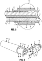
FIG. 5 is a cross-sectional view taken along section line 5-5 ofFIG. 4 with the outer tube and a rotation knob of the surgical clip applier in an advanced position; -
FIG. 6 is a side perspective view of the end effector of the surgical clip applier shown inFIG. 1 with a clip cartridge spaced from the end effector prior to attachment of the clip cartridge to the end effector; -
FIG. 7 is cross-sectional view taken along section line 5-5 ofFIG. 4 with the outer tube and the rotation knob of the surgical clip applier in a retracted position; -
FIG. 8 is a side cross-sectional view of a distal end portion of the surgical clip applier shown inFIG. 1 as the clip cartridge ofFIG. 6 is advanced towards the surgical clip applier; -
FIG. 9 is a side cross-sectional view of the distal end portion of the surgical clip applier and the clip cartridge shown inFIG. 8 as the clip cartridge engages the end effector of the surgical clip applier; -
FIG. 10 is a side cross-sectional view of the distal end portion of the surgical clip applier and the clip cartridge shown inFIG. 9 with the clip cartridge engaged with the end effector of the surgical clip applier and the outer tube in its advanced position; -
FIG. 11 is a cross-sectional view taken along section line 11-11 ofFIG. 10 ; -
FIG. 12 is a side perspective view of an alternative end effector of the surgical clip applier shown inFIG. 1 ; -
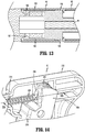
FIG. 13 is a side cross-sectional view of the distal end portion of the surgical clip applier shown inFIG. 1 and clip cartridge shown inFIG. 6 including the end effector shown inFIG. 12 with the outer tube in its advanced position; -
FIG. 14 is a side perspective view of the proximal portion of the surgical clip applier shown inFIG. 1 with a body portion removed and including alternative aspects of the handle assembly; and -
FIG. 15 is a cross-sectional view taken along section line 15-15 ofFIG. 14 . - The disclosed surgical clip applier will now be described in detail with reference to the drawings in which like reference numerals designate identical or corresponding elements in each of the several views. However, it is to be understood that aspects of the disclosure included herein are merely exemplary of the disclosure and may be embodied in various forms. Well-known functions or constructions are not described in detail to avoid obscuring the disclosure in unnecessary detail. Therefore, specific structural and functional details disclosed herein are not to be interpreted as limiting, but merely as a basis for the claims and as a representative basis for teaching one skilled in the art to variously employ the disclosure in virtually any appropriately detailed structure. In addition, directional terms such as front, rear, upper, lower, top, bottom, distal, proximal, and similar terms are used to assist in understanding the description and are not intended to limit the disclosure.
- In this description, the term "proximal" is used generally to refer to that portion of the device that is closer to a clinician, while the term "distal" is used generally to refer to that portion of the device that is farther from the clinician. In addition, the term "endoscopic" is used generally to refer to endoscopic, laparoscopic, arthroscopic, and/or any other procedure conducted through a small diameter incision or cannula. Further, the term "clinician" is used generally to refer to medical personnel including doctors, nurses, and support personnel.
-
FIG. 1 illustrates exemplary aspects of the disclosed clip applier shown generally asclip applier 10. Theclip applier 10 includes ahandle assembly 12, anelongate body 14, and anend effector 16 that is received within adistal end portion 14a of theelongate body 14. Thehandle assembly 12 includes anactuator handle 18 and ahandle body 20 defining astationary handle 22. Thehandle body 20 includes adistal hub portion 20a (FIG. 3 ). Although thehandle assembly 12 is illustrated to have a pistol configuration, other handle configurations are envisioned. In the illustrated configuration, theactuator handle 18 is coupled to thehandle body 20 and can pivot towards thestationary handle 22 to actuate theclip applier 10 as described in further detail below. -
FIG. 2 illustrates an exploded view of theclip applier 10. Thehandle body 20 includes a firsthandle body portion 24 and a secondhandle body portion 26 that are secured together to define thehandle body 20. The first and secondhandle body portions cavity 28 that receives a portion of theactuator handle 18. In aspects of the disclosure, the first andsecond handle portions handle body portion 24 supports a pivot member 30 that is received in abore 32 of the actuator handle 18 to support the actuator handle 18 for pivoting movement in relation to thestationary handle 22. The portion of the actuator handle 18 received within thecavity 28 of thehandle body 20 includes anengagement member 34 that includes acurved engagement surface 34a. Theengagement member 34 moves between retracted and advanced positions within thecavity 24 in response to movement of the actuator handle 18 in relation to thestationary handle 22 through an actuation stroke. - The
elongate body 14 includes an inner shaft 39 (FIG. 5 ), anactuator rod 44, and anouter tube 46. Theinner shaft 39 has a proximal end portion and a distal end portion and is formed from a firstelongate body portion 40 and a secondelongate body portion 42 that are coupled together to define anelongate channel 48 that extends from thehandle assembly 12 through theelongate body 14 to theend effector 16. In aspects of the disclosure, the firstelongate body portion 40 is formed integrally with thefirst handle portion 24 and the secondelongate body portion 42 is formed integrally with thesecond handle portion 26. Alternately, thebody portions handle portions handle assembly 12 using known techniques. The first and secondelongate body portions FIG. 2A ) at thedistal end portion 14a (FIG. 1 ) of theelongate body 14. -
FIGS. 3-5 illustrate internal components of thehandle assembly 12 including theengagement member 34 of theactuator handle 18 and theactuator rod 44. Theactuator rod 44 includes anelongate shaft 50 and aproximal abutment member 52. In aspects of the disclosure, theproximal abutment member 52 of theactuator rod 44 is disc-shaped and is supported within thecavity 28 of thehandle assembly 12. Alternately, theproximal abutment portion 52 of theactuator rod 44 can assume a variety of different configurations. Theelongate shaft 50 of theactuator rod 44 has a proximal end portion 54 (FIG. 3 ) and adistal end portion 56. Theproximal abutment member 52 is secured to, or formed integrally with, theproximal end portion 54 of theactuator rod 44. Thedistal end portion 56 of theactuator rod 44 extends through the end effector 16 (FIG. 4 ). Theactuator rod 44 is movable within theelongate channel 48 of theelongate body 14 in response to actuation of the actuator handle 18 between a retracted position (FIG. 4 ) in which thedistal end portion 56 of theactuator rod 44 is positioned within the end effector 16 (FIG. 4 ) and an advanced position (not shown) in which thedistal end portion 56 of theactuator rod 44 extends distally of theend effector 16 into a clip cartridge 102 (FIG. 6 ). - A biasing member, e.g., a
coil spring 60, is received about theproximal end portion 54 of theactuator rod 44 and is positioned to urge theactuator rod 44 towards its retracted position in which theproximal abutment member 52 of theactuator rod 44 is engaged with theengagement surface 34a of theengagement member 34 of theactuator handle 18. In aspects of the disclosure, thecoil spring 60 is positioned between theproximal abutment member 52 of theactuator rod 44 and aninner wall 64 of thehandle body 20 to urge theactuator rod 44 in the proximal direction. When theactuator handle 18 is pivoted towards the stationary 22, theengagement member 34 of theactuator handle 18 engages theproximal abutment member 52 of theactuator rod 44 to move theactuator rod 44 from its retracted position towards its advanced position against the bias of thecoil spring 60. - The
outer tube 46 of theelongate body 14 includes a distal end portion 62 (FIG. 4 ) and aproximal end portion 63. Theproximal end portion 63 of theouter tube 46 is coupled to arotation knob 66. In some aspects of the disclosure, theproximal end portion 63 of theouter tube 46 includes one ormore bores 68a (FIG. 5 ) and one ormore slots 68b (FIG. 2 ) and therotation knob 66 includesprotrusions 70 that are received within thebores 68a andslots 68b to axially and rotatably secure therotation knob 66 to theouter tube 46. Theouter tube 46 and therotation knob 66 are supported about the inner shaft 39 (FIG. 5 ) and is movable between an advanced position (FIG. 4 ) and a retracted position (FIGS. 7 and 8 ). In the advanced position, theouter tube 46 is positioned about and encompasses theend effector 16. In the retracted position, theouter tube 46 is retracted to a position to expose a distal portion of the end effector 16 (FIG. 8 ) as described in further detail below. - The
rotation knob 66 defines a throughbore 66a that receives theproximal end portion 63 of theouter tube 46. A biasing member, e.g., acoil spring 74, is positioned within the throughbore 66a of therotation knob 66 between theproximal end portion 63 of the outer tube 46 (FIG. 5 ) and thedistal hub portion 20a of thehandle body 20 to urge therotation knob 66 distally about theinner shaft 39 of theelongate body 14. As described above, theouter tube 46 is secured to therotation knob 66. Thus, when therotation knob 66 is urged distally by the biasingmember 74 about theinner shaft 39 of theelongate body 14, theouter tube 46 of theelongate body 14 is urged distally about theinner shaft 39 of theelongate body 14 towards its advanced position (FIG. 4 ). -
FIG. 2B illustrates theend effector 16 which includes abody 78 having acentral body portion 80, aproximal body portion 82, a distalkey portion 84, and a pair of diametrically opposedflexible arms 90. In aspects of the disclosure, theflexible arms 90 are formed of spring steel, thebody 78 is formed of a polymeric material, and theflexible arms 90 are secured to thecentral body portion 80 of theend effector 16 using any of a variety of fastening techniques. In one aspect of the disclosure, thebody 78 is molded about theflexible arms 90. - The
body 78 of theend effector 16 defines a central throughbore 88 that receives theactuator rod 44. Thecentral body portion 80 of theend effector 16 is substantially cylindrical and is received in thedistal end portion 62 of theouter tube 46. Thecentral body portion 80 has an outer diameter that is substantially equal to the inner diameter of theouter tube 46 of theelongate body 14. Theproximal body portion 82 of thebody 78 of theend effector 16 is cylindrical and is received within the cylindrical recess 43 (FIG. 2A ) of theinner shaft 39 within thedistal end portion 14a (FIG. 1 ) of theelongate body 14 to fixedly secure theend effector 16 to the distal end portion of theinner shaft 39. Acylindrical metal bearing 86 is secured about theproximal body portion 82 of thebody 78 of theend effector 16. It is noted that in certain aspects of the disclosure, theinner shaft 39 of theelongate body 14 and theend effector 16 are formed from polymeric materials. Themetal bearing 86 provides added strength to the connection between theinner shaft 39 and theend effector 16. - The diametrically opposed
flexible arms 90 each includes an inwardly extendingprotrusion 92. In aspects of the disclosure, theprotrusions 92 include tapered distal and proximal surfaces that allow theflexible arms 90 of theend effector 16 to be deformed about theclip cartridge 100 to allow theprotrusions 92 of theend effector 16 to be received within recesses 106 (FIG. 6 ) defined within theclip cartridge 100 as described in further detail below. -
FIG. 6 illustrates theclip cartridge 100 as theclip cartridge 100 is secured to theend effector 16 of theclip applier 100. Theclip cartridge 100 includes abody 102 that supports a plurality of clips (not shown). SeeU.S. Patent Nos. 5,354,304 and5,972,003 for a detailed description of exemplary aspects of a clip cartridge. Theclip cartridge 100 includes a proximal body portion including acoupling portion 104. Thecoupling portion 104 includesrecesses 106 that are diametrically opposed to each other and receive theprotrusions 92 on theflexible arms 90 of theend effector 16 when theclip cartridge 100 is coupled to theclip applier 10. Thecoupling portion 104 also defines atransverse slot 108 that receives the distalkey portion 84 of theend effector 16 to rotatably secure theclip cartridge 100 onto theend effector 16 when theclip cartridge 100 is coupled to the clip applier 10 (FIG. 1 ). -
FIGS. 7-11 illustrate theclip applier 10 as aclip cartridge 100 is coupled to theend effector 16 of theclip applier 10. When theclip cartridge 100 is coupled to theend effector 16, therotation knob 66 is pulled proximally towards thehandle assembly 12 in the direction of arrows "A" inFIG. 7 against the urging of the biasingmember 74 to position therotation knob 66 about thedistal hub portion 20a of thehandle body 20 of thehandle assembly 12. As therotation knob 66 is moved in the direction of arrows "A", theouter tube 46 is moved from its advanced position (FIG. 4 ) to its retracted position (FIG. 8 ) in the direction of arrows "B" inFIG. 8 to expose theflexible arms 90 of theend effector 16. While maintaining theouter tube 46 of theelongate body 14 in its retracted position, thecoupling portion 104 of theclip cartridge 100 is moved in the direction of arrows "B" inFIG. 8 between theflexible arms 90 of theend effector 16. - When the
coupling portion 104 of theclip cartridge 100 engages the tapered distal surface of theflexible arms 90 of theend effector 16, theflexible arms 90 are deformed outwardly in the direction indicated by arrows "D" inFIG. 9 and pass over the outer surface of thecoupling portion 104 of theclip cartridge 100. In aspects of the disclosure, thecoupling portion 104 includes flats 110 (FIG. 6 ) that theflexible arms 90 ride along as theclip cartridge 100 is moved in the direction of arrow "C" inFIGS. 8 and9 until theprotrusions 92 of theflexible arms 90 become aligned with therecesses 106 in thecoupling portion 104 of theclip cartridge 100. When theprotrusions 92 of theflexible arms 90 become aligned with therecesses 106 in thecoupling portion 104 of theclip cartridge 100, theflexible arms 90 snap inwardly in the direction indicated by arrows "E" into therecesses 106 of theclip cartridge 100 to secure theclip cartridge 100 onto theend effector 16 of theclip applier 10. Once theprotrusions 92 are received within therecesses 106, the rotation knob 66 (FIG. 7 ) can be released to allow thecoil spring 74 to move theouter tube 46 in the direction of arrows "F" inFIG. 10 back to its advanced position. In its advanced position, thedistal end portion 62 of theouter tube 46 is positioned about theflexible arms 90 of theend effector 16 to prevent outward movement of theflexible arms 90 and retain theprotrusions 92 of theflexible arms 90 within therecesses 106 of theclip cartridge 100. This prevents separation of theclip cartridge 100 from theend effector 16 to secure theclip cartridge 100 on theclip applier 10. In aspects of the disclosure, theouter tube 46 includes inwardly extendingtabs 120 that engage theproximal face 100a of theclip cartridge 100 when theouter tube 46 is in its advanced position. -
FIG. 11 illustrates a cross-sectional view of theclip cartridge 100 secured to theend effector 16 of theclip applier 10. As illustrated, when theclip cartridge 100 is secured to theend effector 16, the distalkey portion 84 of theend effector 16 is received in thetransverse slot 108 of theclip cartridge 100. Receipt of the distalkey portion 84 of theend effector 16 within thetransverse slot 108 of theclip cartridge 100 prevents theclip cartridge 100 from rotating in relation to theend effector 100. -
FIGS. 12 and13 illustrate an alternative an end effector of theclip applier 10 which is shown generally asend effector 116. Theend effector 116 is substantially the same as the end effector 16 (FIG. 16) except that theflexible arms 190 including theprotrusions 192 are integrally and monolithically formed with thebody 178 of theend effector 116. In certain aspects of the disclosure, theend effector 116 including theflexible arms 190 is molded from a polymeric material. Alternately, other materials of construction are envisioned including metals, ceramics, or the like. -
FIGS. 14 and15 illustrate an alternative handle assembly of theclip applier 10 shown generally ashandle assembly 212. Thehandle assembly 212 is substantially similar to the handle assembly 12 (FIG. 3 ) except that theproximal end portion 254 of theactuation rod 244 includes anoval ring 256 and theengagement member 234 of theactuator handle 218 includes aslot 220. Theslot 220 receives theoval ring 256 of theactuation rod 244 to prevent theactuation rod 244 from rotating in relation to theactuator handle 218. Theactuator handle 218 andactuation rod 244 function in the same manner as theactuation rod 44 and theactuator handle 18 and will not be described in further detail herein. - Persons skilled in the art will understand that the devices and methods specifically described herein and illustrated in the accompanying drawings are non-limiting exemplary aspects of the disclosure. It is envisioned that the elements and features illustrated or described in connection with one exemplary embodiment may be combined with the elements and features of another without departing from the scope of the present disclosure. As well, one skilled in the art will appreciate further features and advantages of the disclosure based on the above-described aspects of the disclosure. Accordingly, the disclosure is not to be limited by what has been particularly shown and described, except as indicated by the appended claims.
- The invention may be described by reference to the following numbered paragraphs:
- 1. A clip applier comprising: a handle assembly including a handle body and a movable handle, the handle body defining a stationary handle and a cavity; an elongate body including an outer tube, an inner shaft, and an actuator rod, the inner shaft including a proximal end portion and a distal end portion and defining a channel that extends from the handle assembly through the outer tube, the proximal end portion of the inner shaft secured to the handle body, the actuator rod including a proximal end portion and a distal end portion and extending from within the cavity of the handle body through the channel and movable from a retracted position to an advanced position in response to actuation of the movable handle, the outer tube including a distal end portion and a proximal end portion, the outer tube positioned about the inner shaft and movable from a retracted position to an advanced position; and an end effector fixedly supported on the distal end portion of the inner shaft within the outer tube, the end effector including spaced flexible arms, each of the spaced flexible arms including an inwardly extending protrusion, wherein in its advanced position the outer tube is positioned about the spaced flexible arms of the end effector to prevent outward deflection of the flexible arms of the end effector and, in its retracted position the outer tube is moved to a position to allow outward deflection of the spaced flexible arms of the end effector.
- 2. The clip applier of paragraph 1, further including a biasing member positioned to urge the outer tube towards the advanced position.
- 3. The clip applier of paragraph 2, further including a rotation knob secured to the proximal end portion of the outer tube, the rotation knob movable from an advanced position to a retracted position to move the outer tube from its advanced position to its retracted position.
- 4. The clip applier of paragraph 3, wherein the biasing member includes a coil spring that is received about the proximal end portion of the inner shaft within the rotation knob.
- 5. The clip applier of paragraph 1, wherein the end effector includes a body formed of a polymeric material and the spaced flexible arms are formed of spring steel and are secured to the body of the end effector.
- 6. The clip applier of
paragraph 5, wherein the body of the end effector is molded about the spaced flexible arms. - 7. The clip applier of paragraph 1, wherein the end effector includes a body that is monolithically formed with the spaced flexible arms of the end effector.
- 8. The clip applier of paragraph 1, wherein the movable handle includes an engagement member positioned within the cavity of the handle body and movable between retracted and advanced positions to move the actuator rod between its advanced and retracted positions.
- 9. The clip applier of paragraph 8, wherein the engagement member includes an engagement surface and the proximal end portion of the actuator rod includes an abutment member, the engagement surface engaged with the abutment member such that actuation of the movable handle causes movement of the actuator rod from its retracted position to its advanced position.
- 10. The clip applier of paragraph 9, wherein the abutment member is disc-shaped, and the engagement surface is curved.
- 11. The clip applier of paragraph 9, wherein the engagement member defines a slot and the abutment member includes an oval ring that is received within the slot.
- 12. The clip applier of paragraph 1, wherein the distal end portion of the inner shaft of the elongate body defines a cylindrical cavity and the end effector includes a cylindrical body portion that is received within the cylindrical cavity to secure the end effector to the distal end portion of the inner shaft.
- 13. The clip applier of
paragraph 12, further including a metal bearing positioned about the proximal body portion of the end effector within the cylindrical cavity of the inner shaft of the elongate body. - 14. The clip applier of paragraph 8, further including a biasing member positioned about the proximal end portion of the actuator rod to urge the actuator rod towards its retracted position.
- 15. A clip applier comprising: a handle assembly including a handle body and a movable handle, the handle body defining a stationary handle and a cavity; an elongate body including an outer tube and an inner shaft, the inner shaft including a proximal end portion and a distal end portion and defining a channel that extends from the handle assembly through the outer tube, the proximal end portion of the inner shaft secured to the handle body, the outer tube including a distal end portion and a proximal end portion, the outer tube positioned about the inner shaft and movable from a retracted position to an advanced position; and an end effector fixedly supported on the distal end portion of the inner shaft within the outer tube, the end effector including spaced flexible arms, each of the spaced flexible arms including an inwardly extending protrusion, wherein in its advanced position the outer tube is positioned about the spaced flexible arms of the end effector to prevent outward deflection of the flexible arms of the end effector and, in its retracted position the outer tube is moved to a position to allow outward deflection of the spaced flexible arms of the end effector.
- 16. The clip applier of
paragraph 15, further including a biasing member positioned to urge the outer tube towards the advanced position. - 17. The clip applier of
paragraph 16, further including a rotation knob secured to the proximal end portion of the outer tube, the rotation knob movable from an advanced position to a retracted position to move the outer tube from its advanced position to its retracted position. - 18. The clip applier of
paragraph 15, wherein the end effector includes a body formed of a polymeric material and the spaced flexible arms are formed of spring steel and are secured to the body of the end effector. - 19. The clip applier of
paragraph 15, wherein the end effector includes a body that is monolithically formed with the spaced flexible arms of the end effector. - 20. A clip applier comprising: a handle assembly including a handle body and a movable handle, the handle body defining a stationary handle and a cavity; an elongate body including an outer tube, an inner shaft, and an actuator rod, the inner shaft including a proximal end portion and a distal end portion and defining a channel that extends from the handle assembly through the outer tube, the proximal end portion of the inner shaft secured to the handle body, the actuator rod including a proximal end portion and a distal end portion and extending from within the cavity of the handle body through the channel and movable from a retracted position to an advanced position in response to actuation of the movable handle, the outer tube including a distal end portion and a proximal end portion, the outer tube positioned about the inner shaft and movable from a retracted position to an advanced position; an end effector fixedly supported on the distal end portion of the inner shaft within the outer tube, the end effector including spaced flexible arms, each of the spaced flexible arms including an inwardly extending protrusion, wherein in its advanced position the outer tube is positioned about the spaced flexible arms of the end effector to prevent outward deflection of the flexible arms of the end effector and, in its retracted position the outer tube is moved to a position to allow outward deflection of the spaced flexible arms of the end effector; a first biasing member positioned to urge the outer tube towards the advanced position; and a second biasing member positioned about the proximal end portion of the actuator rod to urge the actuator rod to its retracted position.
Claims (15)
- A clip applier comprising:a handle assembly including a handle body and a movable handle, the handle body defining a stationary handle and a cavity;an elongate body including an outer tube, an inner shaft, and an actuator rod, the inner shaft including a proximal end portion and a distal end portion and defining a channel that extends from the handle assembly through the outer tube, the proximal end portion of the inner shaft secured to the handle body, the actuator rod including a proximal end portion and a distal end portion and extending from within the cavity of the handle body through the channel and movable from a retracted position to an advanced position in response to actuation of the movable handle, the outer tube including a distal end portion and a proximal end portion, the outer tube positioned about the inner shaft and movable from a retracted position to an advanced position; andan end effector fixedly supported on the distal end portion of the inner shaft within the outer tube, the end effector including spaced flexible arms, each of the spaced flexible arms including an inwardly extending protrusion, wherein in its advanced position the outer tube is positioned about the spaced flexible arms of the end effector to prevent outward deflection of the flexible arms of the end effector and, in its retracted position the outer tube is moved to a position to allow outward deflection of the spaced flexible arms of the end effector.
- The clip applier of claim 1, further including a biasing member positioned to urge the outer tube towards the advanced position.
- The clip applier of claim 2, further including a rotation knob secured to the proximal end portion of the outer tube, the rotation knob movable from an advanced position to a retracted position to move the outer tube from its advanced position to its retracted position.
- The clip applier of claim 3, wherein the biasing member includes a coil spring that is received about the proximal end portion of the inner shaft within the rotation knob.
- The clip applier of any preceding claim, wherein the end effector includes a body formed of a polymeric material and the spaced flexible arms are formed of spring steel and are secured to the body of the end effector; preferably wherein the body of the end effector is molded about the spaced flexible arms.
- The clip applier of any of claims 1 to 4, wherein the end effector includes a body that is monolithically formed with the spaced flexible arms of the end effector; and/or wherein the movable handle includes an engagement member positioned within the cavity of the handle body and movable between retracted and advanced positions to move the actuator rod between its advanced and retracted positions.
- The clip applier of claim 6, wherein the engagement member includes an engagement surface and the proximal end portion of the actuator rod includes an abutment member, the engagement surface engaged with the abutment member such that actuation of the movable handle causes movement of the actuator rod from its retracted position to its advanced position; preferably wherein the abutment member is disc-shaped, and the engagement surface is curved.
- The clip applier of claim 7, wherein the engagement member defines a slot and the abutment member includes an oval ring that is received within the slot.
- The clip applier of any preceding claim, wherein the distal end portion of the inner shaft of the elongate body defines a cylindrical cavity and the end effector includes a cylindrical body portion that is received within the cylindrical cavity to secure the end effector to the distal end portion of the inner shaft; preferably further including a metal bearing positioned about the proximal body portion of the end effector within the cylindrical cavity of the inner shaft of the elongate body.
- The clip applier of claim 9, further including a biasing member positioned about the proximal end portion of the actuator rod to urge the actuator rod towards its retracted position.
- A clip applier comprising:a handle assembly including a handle body and a movable handle, the handle body defining a stationary handle and a cavity;an elongate body including an outer tube and an inner shaft, the inner shaft including a proximal end portion and a distal end portion and defining a channel that extends from the handle assembly through the outer tube, the proximal end portion of the inner shaft secured to the handle body, the outer tube including a distal end portion and a proximal end portion, the outer tube positioned about the inner shaft and movable from a retracted position to an advanced position; andan end effector fixedly supported on the distal end portion of the inner shaft within the outer tube, the end effector including spaced flexible arms, each of the spaced flexible arms including an inwardly extending protrusion, wherein in its advanced position the outer tube is positioned about the spaced flexible arms of the end effector to prevent outward deflection of the flexible arms of the end effector and, in its retracted position the outer tube is moved to a position to allow outward deflection of the spaced flexible arms of the end effector.
- The clip applier of claim 11, further including a biasing member positioned to urge the outer tube towards the advanced position; preferably further including a rotation knob secured to the proximal end portion of the outer tube, the rotation knob movable from an advanced position to a retracted position to move the outer tube from its advanced position to its retracted position.
- The clip applier of claim 12, wherein the end effector includes a body formed of a polymeric material and the spaced flexible arms are formed of spring steel and are secured to the body of the end effector.
- The clip applier of claim 12, wherein the end effector includes a body that is monolithically formed with the spaced flexible arms of the end effector.
- A clip applier comprising:a handle assembly including a handle body and a movable handle, the handle body defining a stationary handle and a cavity;an elongate body including an outer tube, an inner shaft, and an actuator rod, the inner shaft including a proximal end portion and a distal end portion and defining a channel that extends from the handle assembly through the outer tube, the proximal end portion of the inner shaft secured to the handle body, the actuator rod including a proximal end portion and a distal end portion and extending from within the cavity of the handle body through the channel and movable from a retracted position to an advanced position in response to actuation of the movable handle, the outer tube including a distal end portion and a proximal end portion, the outer tube positioned about the inner shaft and movable from a retracted position to an advanced position;an end effector fixedly supported on the distal end portion of the inner shaft within the outer tube, the end effector including spaced flexible arms, each of the spaced flexible arms including an inwardly extending protrusion, wherein in its advanced position the outer tube is positioned about the spaced flexible arms of the end effector to prevent outward deflection of the flexible arms of the end effector and, in its retracted position the outer tube is moved to a position to allow outward deflection of the spaced flexible arms of the end effector;a first biasing member positioned to urge the outer tube towards the advanced position; anda second biasing member positioned about the proximal end portion of the actuator rod to urge the actuator rod to its retracted position.
Applications Claiming Priority (2)
| Application Number | Priority Date | Filing Date | Title |
|---|---|---|---|
| US202062958435P | 2020-01-08 | 2020-01-08 | |
| US17/083,022 US11723669B2 (en) | 2020-01-08 | 2020-10-28 | Clip applier with clip cartridge interface |
Publications (1)
| Publication Number | Publication Date |
|---|---|
| EP3847978A1 true EP3847978A1 (en) | 2021-07-14 |
Family
ID=74105809
Family Applications (1)
| Application Number | Title | Priority Date | Filing Date |
|---|---|---|---|
| EP21150345.3A Withdrawn EP3847978A1 (en) | 2020-01-08 | 2021-01-05 | Clip applier with clip cartridge interface |
Country Status (2)
| Country | Link |
|---|---|
| US (1) | US11723669B2 (en) |
| EP (1) | EP3847978A1 (en) |
Families Citing this family (2)
| Publication number | Priority date | Publication date | Assignee | Title |
|---|---|---|---|---|
| EP4215130B1 (en) * | 2020-09-18 | 2026-05-06 | IntoCare Medical Technology (Suzhou) Co., Ltd. | Adapter for clip applier, and clip applier |
| US20230309996A1 (en) * | 2022-03-29 | 2023-10-05 | Cilag Gmbh International | Surgical stapler cartridge with support features |
Citations (5)
| Publication number | Priority date | Publication date | Assignee | Title |
|---|---|---|---|---|
| US5354304A (en) | 1992-10-13 | 1994-10-11 | American Cyanamid Co. | Modular ligation clip applicator |
| US5972003A (en) | 1997-10-01 | 1999-10-26 | Sherwood Services Ag | Single-free ligation clip module |
| WO2016197350A1 (en) * | 2015-06-11 | 2016-12-15 | Covidien Lp | Endoscopic reposable surgical clip applier |
| US20180116671A1 (en) * | 2016-10-31 | 2018-05-03 | Covidien Lp | Ligation clip module and clip applier |
| US20190104926A1 (en) * | 2016-07-11 | 2019-04-11 | Olympus Corporation | Endoscope treatment tool |
Family Cites Families (782)
| Publication number | Priority date | Publication date | Assignee | Title |
|---|---|---|---|---|
| US3120230A (en) | 1960-10-24 | 1964-02-04 | Jack H Sanders | Surgical clamp |
| US3363628A (en) | 1964-09-28 | 1968-01-16 | Peter B Samuels | Hemostatic clip |
| US3735762A (en) | 1970-04-27 | 1973-05-29 | Us Corp Baltimo E | Instrument for ligating suturing and dividing organic tubular structures |
| US3675688A (en) | 1970-04-27 | 1972-07-11 | United States Surgical Corp | Instrument for ligating, suturing and dividing organic tubular structures |
| US3638847A (en) | 1970-07-06 | 1972-02-01 | United States Surgical Corp | Ratchet-driven cartridge for surgical instruments |
| US3867944A (en) | 1972-10-27 | 1975-02-25 | Wood Ernest C | Hemostatic clip and applicator therefor |
| US4412539A (en) | 1976-10-08 | 1983-11-01 | United States Surgical Corporation | Repeating hemostatic clip applying instruments and multi-clip cartridges therefor |
| US4226242A (en) | 1977-09-13 | 1980-10-07 | United States Surgical Corporation | Repeating hemostatic clip applying instruments and multi-clip cartridges therefor |
| US4611595A (en) | 1977-08-05 | 1986-09-16 | Charles H. Klieman | Spring activated hemostatic clip applicator |
| CA1124605A (en) | 1977-08-05 | 1982-06-01 | Charles H. Klieman | Surgical stapler |
| US4242902A (en) | 1978-05-11 | 1981-01-06 | United States Surgical Corporation | Surgical clip applicator |
| CA1134701A (en) | 1977-10-17 | 1982-11-02 | David T. Green | Surgical clip applicator |
| US4418694A (en) | 1979-06-18 | 1983-12-06 | Ethicon, Inc. | Non-metallic, bio-compatible hemostatic clips |
| US4372316A (en) | 1979-08-02 | 1983-02-08 | Blake Joseph W Iii | Surgical device |
| US4662374A (en) | 1979-08-02 | 1987-05-05 | American Hospital Supply Corp. | Ligator device |
| US4296751A (en) | 1979-08-02 | 1981-10-27 | Blake Joseph W Iii | Surgical device |
| US4532925A (en) | 1979-08-02 | 1985-08-06 | Joseph W. Blake, III | Ligator device |
| US4480640A (en) | 1980-04-22 | 1984-11-06 | Senco Products, Inc. | Ligating device |
| US4408603A (en) | 1980-10-24 | 1983-10-11 | Blake Joseph W Iii | Surgical device |
| US4500024A (en) | 1980-11-19 | 1985-02-19 | Ethicon, Inc. | Multiple clip applier |
| CA1163889A (en) | 1981-02-02 | 1984-03-20 | Allegiance Corporation | Surgical device |
| US4522207A (en) | 1981-02-06 | 1985-06-11 | Charles H. Klieman | Spring activated hemostatic clip applicator |
| US4646740A (en) | 1981-02-23 | 1987-03-03 | Edward Weck & Co., Inc. | Automatic hemoclip applier |
| US4662373A (en) | 1981-06-29 | 1987-05-05 | American Cyanamid Company | Surgical ligating instrument |
| US4576166A (en) | 1981-06-29 | 1986-03-18 | American Cyanamid Company | Surgical ligating instrument |
| US4498476A (en) | 1981-08-27 | 1985-02-12 | Ethicon, Inc. | Non-metallic, bio-compatible hemostatic clips with interlocking latch means |
| US4487204A (en) | 1981-10-14 | 1984-12-11 | Nomel | Device for applying haemostatic clips |
| US4471780A (en) | 1982-02-05 | 1984-09-18 | Ethicon, Inc. | Multiple ligating clip applier instrument |
| US4480641A (en) | 1982-02-05 | 1984-11-06 | Ethicon, Inc. | Tip configuration for a ligating clip applier |
| US4491133A (en) | 1982-02-05 | 1985-01-01 | Ethicon, Inc. | Folding cartridge for a multiple clip applier |
| US4509518A (en) | 1982-02-17 | 1985-04-09 | United States Surgical Corporation | Apparatus for applying surgical clips |
| US4487205A (en) | 1982-04-26 | 1984-12-11 | Ethicon, Inc. | Non-metallic, bio-compatible hemostatic clips |
| US4545377A (en) | 1982-09-24 | 1985-10-08 | Ethicon, Inc. | Non-metallic, bio-compatible hemostatic clips (two piece configured to lock tighter the larger the vessel being closed) |
| US4815466A (en) | 1982-09-30 | 1989-03-28 | Perlin Alfred R | Surgical clip |
| US4492232A (en) | 1982-09-30 | 1985-01-08 | United States Surgical Corporation | Surgical clip applying apparatus having fixed jaws |
| US4512345A (en) | 1982-09-30 | 1985-04-23 | United States Surgical Corporation | Surgical clip applying apparatus, and clips and clip train for use therein |
| US4674504A (en) | 1982-10-06 | 1987-06-23 | Klieman Charles H | Spring activated hemostatic clip applicator |
| US4534351A (en) | 1982-10-20 | 1985-08-13 | Senmed, Inc. | Ligator |
| US4796625A (en) | 1982-11-15 | 1989-01-10 | Codman & Shurtleff, Inc. | Aneurysm clip |
| US4562839A (en) | 1983-01-06 | 1986-01-07 | Blake Joseph W Iii | Surgical instrument |
| US4556058A (en) | 1983-08-17 | 1985-12-03 | United States Surgical Corporation | Apparatus for ligation and division with fixed jaws |
| US4602631A (en) | 1983-09-08 | 1986-07-29 | Noboru Funatsu | Forceps for clamping surgical clips |
| US4637395A (en) | 1983-10-04 | 1987-01-20 | Aesculap-Werke Ag | Applicator for C-shaped scalp clips |
| DE3335985C2 (en) | 1983-10-04 | 1986-12-04 | Aesculap-Werke Ag Vormals Jetter & Scheerer, 7200 Tuttlingen | Magazine for holding C-shaped scalp clips |
| US4549544A (en) | 1983-10-31 | 1985-10-29 | Senmed, Inc. | Clip stop for a surgical ligating instrument |
| US4576165A (en) | 1984-01-23 | 1986-03-18 | United States Surgical Corporation | Surgical ligation and cutting device with safety means |
| US4557263A (en) | 1984-01-23 | 1985-12-10 | United States Surgical Corporation | Apparatus for applying surgical clips |
| US4616650A (en) | 1984-07-27 | 1986-10-14 | United States Surgical Corporation | Apparatus for applying surgical clips |
| US4598711A (en) | 1984-08-09 | 1986-07-08 | American Cyanamid Company | Surgical instrument |
| US4590937A (en) | 1985-01-07 | 1986-05-27 | American Cyanamid Company | Nonmetallic surgical clip |
| US5127915A (en) | 1984-10-29 | 1992-07-07 | Mattson Philip D | Surgical instrument for severing and clamping an umbilical cord |
| US4572183A (en) | 1984-11-26 | 1986-02-25 | Senmed, Inc. | Positive feed system for a surgical ligating instrument |
| GB2168990B (en) | 1984-12-22 | 1988-07-06 | Hoechst Gosei Kk | Dispersion of solvent-suspendible pressure sensitive adhesive particles and pressure sensitive adhesive sheet utilizing the dispersion |
| US4671278A (en) | 1985-01-14 | 1987-06-09 | Thomas J. Fogarty | Scalp hemostatic clip and dispenser therefor |
| US4821721A (en) | 1985-01-14 | 1989-04-18 | Thomas J. Fogarty | Apparatus and method for applying hemostatic scalp clips |
| US5122150A (en) | 1985-03-27 | 1992-06-16 | Puig Ana E | Neurosurgical clip applier |
| US4616651A (en) | 1985-04-15 | 1986-10-14 | Ethicon, Inc. | Surgical clip applier instrument adapter jaws |
| US4712549A (en) | 1985-07-01 | 1987-12-15 | Edward Weck & Co. | Automatic hemostatic clip applier |
| US5047038A (en) | 1985-07-01 | 1991-09-10 | Edward Weck Incorporated | Automatic hemostatic clip applier |
| US4702247A (en) | 1985-08-20 | 1987-10-27 | American Hospital Supply Corporation | Ligating clip |
| US4674817A (en) * | 1985-09-13 | 1987-06-23 | Tronomed, Inc. | Medical terminal clip |
| US4706668A (en) | 1985-09-16 | 1987-11-17 | B & B Tools | Aneurysm clip pliers |
| DE3533423A1 (en) | 1985-09-19 | 1987-03-26 | Wolf Gmbh Richard | APPLICATOR PLIERS FOR SURGICAL HANDLING FOR USE IN ENDOSCOPY |
| US4671282A (en) | 1985-10-04 | 1987-06-09 | Tretbar Lawrence L | Clip apparatus |
| US4696396A (en) | 1985-12-19 | 1987-09-29 | Samuels Peter B | Hemostatic clip cartridge |
| US4681107A (en) | 1985-12-31 | 1987-07-21 | Kees Surgical Specialty Co. | Device for holding an aneurysm clip |
| US4660558A (en) | 1985-12-31 | 1987-04-28 | Kees Jr George | Aneurysm clip and method of manufacture |
| US4658822A (en) | 1985-12-31 | 1987-04-21 | Kees Jr George | Aneurysm clip |
| US4733666A (en) | 1986-01-13 | 1988-03-29 | Texas Tech University Health Sciences Center | Surgical clip for cholangiography |
| US4967949A (en) | 1986-07-11 | 1990-11-06 | Vastech Medical Products Inc. | Apparatus for effecting occlusion of the vas deferens |
| US4726372A (en) | 1986-09-19 | 1988-02-23 | Metatech Corporation | Hemostatic clip |
| US4856517A (en) | 1986-09-22 | 1989-08-15 | Collins Jason H | Umbilical cord clamp apparatus |
| DE3704760C1 (en) | 1987-02-16 | 1988-03-03 | Aesculap Werke Ag | Application device for C-shaped scalp clips |
| US4929239A (en) | 1987-02-16 | 1990-05-29 | Aesculap-Werke Ag Vormals Jetter & Scheerer | Device for filling the magazine of a scalp clip applicator with C-shaped scalp clips |
| US4765335A (en) | 1987-03-16 | 1988-08-23 | Intermar, Inc. | Aneurysm clip |
| US4850355A (en) | 1987-04-06 | 1989-07-25 | Richard-Allan Medical Industries, Inc. | Hemostatic clip applicator for applying multiple hemostatic clips |
| US4799481A (en) | 1987-04-08 | 1989-01-24 | Ethicon, Inc. | Surgical hemostatic clips |
| US4777949A (en) | 1987-05-08 | 1988-10-18 | Metatech Corporation | Surgical clip for clamping small blood vessels in brain surgery and the like |
| US4822348A (en) | 1987-05-13 | 1989-04-18 | Donn Casey | Surgical clips |
| US5542949A (en) | 1987-05-14 | 1996-08-06 | Yoon; Inbae | Multifunctional clip applier instrument |
| US5171250A (en) | 1987-05-14 | 1992-12-15 | Inbae Yoon | Surgical clips and surgical clip applicator and cutting and transection device |
| US5366459A (en) | 1987-05-14 | 1994-11-22 | Inbae Yoon | Surgical clip and clip application procedures |
| US4834096A (en) | 1987-10-26 | 1989-05-30 | Edward Weck Incorporated | Plastic ligating clips |
| GB2212201B (en) | 1987-11-10 | 1992-06-03 | Donn Casey | Surgical clip |
| US6974475B1 (en) | 1987-12-08 | 2005-12-13 | Wall W Henry | Angioplasty stent |
| US5030226A (en) | 1988-01-15 | 1991-07-09 | United States Surgical Corporation | Surgical clip applicator |
| US5197970A (en) | 1988-01-15 | 1993-03-30 | United States Surgical Corporation | Surgical clip applicator |
| US5129885A (en) | 1990-02-13 | 1992-07-14 | United States Surgical Corporation | Safety device for trocars and surgical instruments therefor |
| US5100420A (en) | 1989-07-18 | 1992-03-31 | United States Surgical Corporation | Apparatus and method for applying surgical clips in laparoscopic or endoscopic procedures |
| US5383881A (en) | 1989-07-18 | 1995-01-24 | United States Surgical Corporation | Safety device for use with endoscopic instrumentation |
| US5084057A (en) | 1989-07-18 | 1992-01-28 | United States Surgical Corporation | Apparatus and method for applying surgical clips in laparoscopic or endoscopic procedures |
| US5049152A (en) | 1989-03-07 | 1991-09-17 | Richard-Allan Medical Industries | Hemostatic clip applicator |
| US5053045A (en) | 1988-09-16 | 1991-10-01 | Schmidt Ferenc J | Surgical clip |
| FR2637489A1 (en) | 1988-10-07 | 1990-04-13 | Lachkar Alain | AUTOMATIC CLIPS CLIP |
| US5059202A (en) | 1988-10-27 | 1991-10-22 | The Montefiore Hospital Association Of Western Pennsylvania | Tendon approximator |
| US4957500A (en) | 1988-10-27 | 1990-09-18 | Montefiore Hospital Association Of Western Pennsylvania | Normally closed clamp |
| US4983176A (en) | 1989-03-06 | 1991-01-08 | University Of New Mexico | Deformable plastic surgical clip |
| US5062846A (en) | 1989-03-28 | 1991-11-05 | Edward Weck Incorporated | Penetrating plastic ligating clip |
| US5062563A (en) | 1989-04-10 | 1991-11-05 | United States Surgical Corporation | Fascia stapler |
| CA2018472A1 (en) | 1989-07-03 | 1991-01-03 | Curtis W. Thornton | Automatic hemostatic clip applicator |
| US5104395A (en) | 1989-07-03 | 1992-04-14 | Edward Weck Incorporated | Automatic hemostatic clip applicator |
| US5382254A (en) | 1989-07-18 | 1995-01-17 | United States Surgical Corporation | Actuating handle for surgical instruments |
| US4966603A (en) | 1989-07-24 | 1990-10-30 | Rms Company | Aneurysm clip |
| US4931058A (en) | 1989-08-16 | 1990-06-05 | Applied Vascular Devices, Inc. | Parallel jaw spring clip and method of making same |
| US5030224A (en) | 1989-09-25 | 1991-07-09 | Pioneering Technologies, Inc. | Coronary artery retraction clip |
| US5100416A (en) | 1989-10-17 | 1992-03-31 | Edward Weck Incorporated | Ligating clip applying instrument |
| US5026379A (en) | 1989-12-05 | 1991-06-25 | Inbae Yoon | Multi-functional instruments and stretchable ligating and occluding devices |
| US5217473A (en) | 1989-12-05 | 1993-06-08 | Inbae Yoon | Multi-functional instruments and stretchable ligating and occluding devices |
| US5049153A (en) | 1989-12-26 | 1991-09-17 | Nakao Naomi L | Endoscopic stapling device and method |
| US4988355A (en) | 1990-01-16 | 1991-01-29 | Leveen Eric G | Arterial clamp |
| US5035692A (en) | 1990-02-13 | 1991-07-30 | Nicholas Herbert | Hemostasis clip applicator |
| US5032127A (en) | 1990-03-07 | 1991-07-16 | Frazee John G | Hemostatic clip and applicator therefor |
| US5078731A (en) | 1990-06-05 | 1992-01-07 | Hayhurst John O | Suture clip |
| DE4024106C1 (en) | 1990-07-30 | 1992-04-23 | Ethicon Gmbh & Co Kg, 2000 Norderstedt, De | |
| US5207692A (en) | 1990-07-30 | 1993-05-04 | Codman & Shurtleff, Inc. | Surgical clip applier with reciprocating clip sleeve and dual ratchet mechanism |
| US5104394A (en) | 1990-11-05 | 1992-04-14 | Knoepfler Dennis J | Automatic stapler for laparoscopic procedure with selective cutter and suction irrigator |
| US5282807A (en) | 1990-11-05 | 1994-02-01 | Knoepfler Dennis J | Automatic stapler for laparoscopic procedure with selective cutter, nontraumatic jaws and suction irrigator |
| USRE36720E (en) | 1990-12-13 | 2000-05-30 | United States Surgical Corporation | Apparatus and method for applying latchless surgical clips |
| US5366458A (en) | 1990-12-13 | 1994-11-22 | United States Surgical Corporation | Latchless surgical clip |
| US5171252A (en) | 1991-02-05 | 1992-12-15 | Friedland Thomas W | Surgical fastening clip formed of a shape memory alloy, a method of making such a clip and a method of using such a clip |
| US5171253A (en) | 1991-03-22 | 1992-12-15 | Klieman Charles H | Velcro-like closure system with absorbable suture materials for absorbable hemostatic clips and surgical strips |
| US5171247A (en) | 1991-04-04 | 1992-12-15 | Ethicon, Inc. | Endoscopic multiple ligating clip applier with rotating shaft |
| US5395375A (en) | 1992-11-18 | 1995-03-07 | Symbiosis Corporation | Arthroscopic surgical instruments |
| US5171249A (en) | 1991-04-04 | 1992-12-15 | Ethicon, Inc. | Endoscopic multiple ligating clip applier |
| US5359993A (en) | 1992-12-31 | 1994-11-01 | Symbiosis Corporation | Apparatus for counting the number of times a medical instrument has been used |
| US5112343A (en) | 1991-04-05 | 1992-05-12 | Edward Weck Incorporated | Endoscopic clip appliers |
| EP0596543B1 (en) | 1991-05-14 | 1999-08-11 | United States Surgical Corporation | Surgical stapler with spent cartridge sensing and lockout means |
| US5160339A (en) | 1991-06-18 | 1992-11-03 | Ethicon, Inc. | Endoscopic suture clip |
| US5201746A (en) | 1991-10-16 | 1993-04-13 | United States Surgical Corporation | Surgical hemostatic clip |
| US5163945A (en) | 1991-10-18 | 1992-11-17 | Ethicon, Inc. | Surgical clip applier |
| US5199566A (en) | 1991-10-18 | 1993-04-06 | Ethicon, Inc. | Surgical clip applier |
| US5356064A (en) | 1991-10-18 | 1994-10-18 | United States Surgical Corporation | Apparatus and method for applying surgical staples to attach an object to body tissue |
| US5289963A (en) | 1991-10-18 | 1994-03-01 | United States Surgical Corporation | Apparatus and method for applying surgical staples to attach an object to body tissue |
| US5207691A (en) | 1991-11-01 | 1993-05-04 | Medical Scientific, Inc. | Electrosurgical clip applicator |
| US5290299A (en) | 1991-12-11 | 1994-03-01 | Ventritex, Inc. | Double jaw apparatus for attaching implanted materials to body tissue |
| US5383880A (en) | 1992-01-17 | 1995-01-24 | Ethicon, Inc. | Endoscopic surgical system with sensing means |
| US6963792B1 (en) | 1992-01-21 | 2005-11-08 | Sri International | Surgical method |
| CA2088883A1 (en) | 1992-02-13 | 1993-08-14 | David T. Green | Endoscopic ligating instrument |
| US5201900A (en) | 1992-02-27 | 1993-04-13 | Medical Scientific, Inc. | Bipolar surgical clip |
| US5219353A (en) | 1992-02-28 | 1993-06-15 | Garvey Iii Thomas Q | Surgical endoclip |
| US5171251A (en) | 1992-03-02 | 1992-12-15 | Ethicon, Inc. | Surgical clip having hole therein and method of anchoring suture |
| CA2090980C (en) | 1992-03-06 | 2004-11-30 | David Stefanchik | Ligating clip applier |
| US5246450A (en) | 1992-03-10 | 1993-09-21 | Edward Weck Incorporated | High capacity medical clip feeding and dispensing mechanism |
| US5304183A (en) | 1992-03-23 | 1994-04-19 | Laparomed Corporation | Tethered clamp retractor |
| CA2094463A1 (en) | 1992-04-28 | 1993-10-29 | Claude Vidal | Vessel clips |
| AU662407B2 (en) | 1992-05-06 | 1995-08-31 | Ethicon Inc. | Endoscopic ligation and division instrument |
| DE4215449C1 (en) | 1992-05-11 | 1993-09-02 | Ethicon Gmbh & Co Kg, 2000 Norderstedt, De | |
| US5431667A (en) | 1992-05-26 | 1995-07-11 | Origin Medsystems, Inc. | Gas-sealed instruments for use in laparoscopic surgery |
| US5192288A (en) | 1992-05-26 | 1993-03-09 | Origin Medsystems, Inc. | Surgical clip applier |
| US5269792A (en) | 1992-05-26 | 1993-12-14 | Origin Medsystems, Inc. | Surgical clip |
| US5658300A (en) | 1992-06-04 | 1997-08-19 | Olympus Optical Co., Ltd. | Tissue fixing surgical instrument, tissue-fixing device, and method of fixing tissues |
| US5906625A (en) | 1992-06-04 | 1999-05-25 | Olympus Optical Co., Ltd. | Tissue-fixing surgical instrument, tissue-fixing device, and method of fixing tissue |
| NL9201118A (en) | 1992-06-24 | 1994-01-17 | Leuven K U Res & Dev | TOOL KIT FOR LAPAROSCOPIC VAGINAL HYSTERECTOMY. |
| US5306283A (en) | 1992-06-30 | 1994-04-26 | American Cyanamid Company | Two-part surgical ligation clip |
| CA2104345A1 (en) | 1992-09-02 | 1994-03-03 | David T. Green | Surgical clamp apparatus |
| US5342373A (en) | 1992-09-14 | 1994-08-30 | Ethicon, Inc. | Sterile clips and instrument for their placement |
| US5868761A (en) | 1992-10-09 | 1999-02-09 | United States Surgical Corporation | Surgical clip applier |
| US5282832A (en) | 1992-10-09 | 1994-02-01 | United States Surgical Corporation | Suture clip |
| US5381943A (en) | 1992-10-09 | 1995-01-17 | Ethicon, Inc. | Endoscopic surgical stapling instrument with pivotable and rotatable staple cartridge |
| US5330442A (en) | 1992-10-09 | 1994-07-19 | United States Surgical Corporation | Suture retaining clip |
| CA2107635C (en) | 1992-10-09 | 1999-08-17 | David T. Green | Surgical clip applier |
| US5300081A (en) | 1992-10-09 | 1994-04-05 | United States Surgical Corporation | Surgical clip applier having clip advancement control |
| US5779718A (en) | 1992-10-09 | 1998-07-14 | United States Surgical Corporation | Method of anastomosing a vessel using a surgical clip applier |
| US5626587A (en) | 1992-10-09 | 1997-05-06 | Ethicon Endo-Surgery, Inc. | Method for operating a surgical instrument |
| CA2133687C (en) | 1992-10-09 | 2007-03-27 | David T. Green | Surgical clip applier |
| US5662662A (en) | 1992-10-09 | 1997-09-02 | Ethicon Endo-Surgery, Inc. | Surgical instrument and method |
| US5409498A (en) | 1992-11-05 | 1995-04-25 | Ethicon, Inc. | Rotatable articulating endoscopic fastening instrument |
| US5464416A (en) | 1992-11-10 | 1995-11-07 | Ethicon, Inc. | Ligating clip |
| US5281228A (en) | 1992-11-23 | 1994-01-25 | Fred Wolfson | Umbilical clamp identification device for infants |
| US5330487A (en) | 1992-12-17 | 1994-07-19 | Tfi Acquistion Corp. | Drive mechanism for surgical instruments |
| US5662679A (en) | 1992-12-21 | 1997-09-02 | Shatzu Health Products, Inc. | Tragus acupressure clip with over-opening prevention and pressure adjustment |
| US5403327A (en) | 1992-12-31 | 1995-04-04 | Pilling Weck Incorporated | Surgical clip applier |
| AU5987494A (en) | 1993-01-07 | 1994-08-15 | Hayhurst, John O. | Clip for suture |
| US5382255A (en) | 1993-01-08 | 1995-01-17 | United States Surgical Corporation | Apparatus and method for assembly of surgical instruments |
| US5569274A (en) | 1993-02-22 | 1996-10-29 | Heartport, Inc. | Endoscopic vascular clamping system and method |
| US5382253A (en) | 1993-03-05 | 1995-01-17 | Unisurge, Inc. | Clip applier tool |
| US5312426A (en) | 1993-03-12 | 1994-05-17 | Mizuho Ika Kogyo Kabushiki Kaisha | Surgical clip |
| FR2702647B1 (en) | 1993-03-18 | 1995-05-05 | Baudet Jacques | Process of micro-anastomosis of blood vessels and automatic clamp for its implementation. |
| CA2120828C (en) | 1993-04-16 | 1999-11-02 | Paul J. Phillips | Surgical hemostatic clip |
| FR2704135B1 (en) | 1993-04-19 | 1995-07-07 | Savornin Claude | OSTEOSYNTHESIS STAPLE. |
| ATE153231T1 (en) | 1993-04-27 | 1997-06-15 | American Cyanamid Co | AUTOMATIC LAPAROSCOPIC APPLICATOR FOR LIVING CLIPS |
| US5431668A (en) | 1993-04-29 | 1995-07-11 | Ethicon, Inc. | Ligating clip applier |
| US5439468A (en) | 1993-05-07 | 1995-08-08 | Ethicon Endo-Surgery | Surgical clip applier |
| DE4319829C1 (en) | 1993-06-16 | 1994-08-25 | Lerch Karl Dieter | Set for treating vascular deformities |
| US5448042A (en) | 1993-06-22 | 1995-09-05 | Unisurge, Inc. | Surgical device with counter for recording usage |
| US5562687A (en) | 1993-07-12 | 1996-10-08 | Mitek Surgical Products, Inc. | Surgical repair kit and its method of use |
| US5431669A (en) | 1993-07-16 | 1995-07-11 | Origin Medsystems, Inc. | Surgical clip applier with distal hook |
| WO1995002365A1 (en) * | 1993-07-17 | 1995-01-26 | Gerhard Schad | Surgical instrument |
| US5827323A (en) | 1993-07-21 | 1998-10-27 | Charles H. Klieman | Surgical instrument for endoscopic and general surgery |
| US5368600A (en) | 1993-07-23 | 1994-11-29 | Ethicon, Inc. | Steerable bulldog clamp applier |
| JPH08504120A (en) | 1993-08-25 | 1996-05-07 | アポロ キャメラ,リミテッド ライアビリティー カンパニー | Surgical ligation clip |
| US5858018A (en) | 1993-08-25 | 1999-01-12 | Apollo Camera, Llc | Low profile tool for applying spring action ligation clips |
| DK110193A (en) | 1993-09-30 | 1995-03-31 | Per Baunsgaard | Terminal device |
| US5542594A (en) | 1993-10-06 | 1996-08-06 | United States Surgical Corporation | Surgical stapling apparatus with biocompatible surgical fabric |
| US5487499A (en) | 1993-10-08 | 1996-01-30 | United States Surgical Corporation | Surgical apparatus for applying surgical fasteners including a counter |
| US5607436A (en) | 1993-10-08 | 1997-03-04 | United States Surgical Corporation | Apparatus for applying surgical clips |
| US5776146A (en) | 1993-10-20 | 1998-07-07 | Applied Medical Resources | Laparoscopic surgical clamp |
| US5776147A (en) | 1993-10-20 | 1998-07-07 | Applied Medical Resources Corporation | Laparoscopic surgical clamp |
| US5496333A (en) | 1993-10-20 | 1996-03-05 | Applied Medical Resources Corporation | Laparoscopic surgical clamp |
| US5462555A (en) | 1993-12-30 | 1995-10-31 | United States Surgical Corporation | Umbilical cord clip and applicator |
| GB9400739D0 (en) | 1994-01-15 | 1994-03-16 | Femcare Ltd | Medical clip |
| US5527320A (en) | 1994-02-10 | 1996-06-18 | Pilling Weck Inc. | Surgical clip applying instrument |
| CH687060A5 (en) | 1994-02-11 | 1996-09-13 | Alice Walder Utz Dr | Piece surgical clip. |
| US5501698A (en) | 1994-02-14 | 1996-03-26 | Heartport, Inc. | Endoscopic microsurgical instruments and methods |
| US5681330A (en) | 1994-03-02 | 1997-10-28 | Ethicon Endo-Surgery, Inc. | Sterile occlusion fasteners and instrument and method for their placement |
| US5833700A (en) | 1995-03-15 | 1998-11-10 | Ethicon Endo-Surgery, Inc. | Sterile occlusion fasteners and instrument and method for their placement |
| CA2143560C (en) | 1994-03-02 | 2007-01-16 | Mark Fogelberg | Sterile occlusion fasteners and instrument and method for their placement |
| DE4415521C2 (en) | 1994-05-04 | 2003-01-30 | Storz Reling Sybill Gesamthand | Instrument for use in endoscopic procedures |
| US5474566A (en) | 1994-05-05 | 1995-12-12 | United States Surgical Corporation | Self-contained powered surgical apparatus |
| USRE38445E1 (en) | 1994-05-05 | 2004-02-24 | Tyco Healthcare Group, Lp | Pistols for setting surgical clamps |
| DE4415891A1 (en) | 1994-05-05 | 1995-11-09 | Wilo Medizintechnik Gmbh | Surgical staple gun |
| US5425740A (en) | 1994-05-17 | 1995-06-20 | Hutchinson, Jr.; William B. | Endoscopic hernia repair clip and method |
| DE4422621C1 (en) | 1994-06-28 | 1995-08-31 | Aesculap Ag | Surgical instrument for gripping, transporting or fixing objects |
| US5501693A (en) | 1994-07-06 | 1996-03-26 | United States Surgical Corporation | Surgical hemostatic clip |
| US5833695A (en) | 1994-07-13 | 1998-11-10 | Yoon; Inbae | Surgical stapling system and method of applying staples from multiple staple cartridges |
| US5697942A (en) | 1994-07-31 | 1997-12-16 | Palti; Yoram | Internal vascular clamp |
| AU694225B2 (en) | 1994-08-02 | 1998-07-16 | Ethicon Endo-Surgery, Inc. | Ultrasonic hemostatic and cutting instrument |
| US5582616A (en) | 1994-08-05 | 1996-12-10 | Origin Medsystems, Inc. | Surgical helical fastener with applicator |
| US5562655A (en) | 1994-08-12 | 1996-10-08 | United States Surgical Corporation | Surgical apparatus having a universal handle for actuating various attachments |
| US5462558A (en) | 1994-08-29 | 1995-10-31 | United States Surgical Corporation | Suture clip applier |
| US5626585A (en) | 1994-09-16 | 1997-05-06 | United States Surgical Corporation | Ligating clip advance |
| DE4434864C2 (en) | 1994-09-29 | 1997-06-19 | United States Surgical Corp | Surgical staple applicator with interchangeable staple magazine |
| US5487746A (en) | 1994-11-23 | 1996-01-30 | Yu; George W. | Surgical clip having a longitudinal opening through which clamped tissue protrudes |
| US5620452A (en) | 1994-12-22 | 1997-04-15 | Yoon; Inbae | Surgical clip with ductile tissue penetrating members |
| US5976159A (en) | 1995-02-24 | 1999-11-02 | Heartport, Inc. | Surgical clips and methods for tissue approximation |
| US6464710B1 (en) | 1995-03-06 | 2002-10-15 | Cook Urological Incorporated | Releasable, surgical clamp |
| US5897565A (en) | 1995-03-06 | 1999-04-27 | Vance Products Incorporated | Releasable, surgical clamp |
| US5695505A (en) | 1995-03-09 | 1997-12-09 | Yoon; Inbae | Multifunctional spring clips and cartridges and applicators therefor |
| DE69518306T2 (en) | 1995-03-15 | 2001-01-25 | Ethicon Endo-Surgery, Inc. | Device for attaching surgical clips |
| US5571121A (en) | 1995-03-28 | 1996-11-05 | Heifetz; Milton D. | Atraumatic clamp for temporary occlusion of blood vessels |
| US5665097A (en) | 1995-04-21 | 1997-09-09 | Baker; John W. | Clip applicator |
| US5748651A (en) | 1995-05-05 | 1998-05-05 | Trumble Navigation Limited | Optimum utilization of pseudorange and range rate corrections by SATPS receiver |
| US5593421A (en) | 1995-06-06 | 1997-01-14 | Bauer; William | Suture element delivery device and method |
| US5814038A (en) | 1995-06-07 | 1998-09-29 | Sri International | Surgical manipulator for a telerobotic system |
| US5653720A (en) | 1995-07-18 | 1997-08-05 | Applied Medical Resources | Surgical clip and method of assembly |
| US5683405A (en) | 1995-08-25 | 1997-11-04 | Research Medical Inc. | Vascular occluder |
| US5676676A (en) | 1995-08-30 | 1997-10-14 | Porter; Wayne | Ligating clip having ramp-shaped vessel-clamping members |
| US5713912A (en) | 1995-08-30 | 1998-02-03 | Stress Management, Inc. | Ligating clip having ramp-shaped vessel clamping members and tool for applying same |
| US5584840A (en) | 1995-09-05 | 1996-12-17 | Ramsey; James E. | Umbilical cord cutting and clamping device |
| DE19534322A1 (en) | 1995-09-15 | 1997-03-20 | Aesculap Ag | Surgical clip, especially a vascular clip |
| US5700270A (en) | 1995-10-20 | 1997-12-23 | United States Surgical Corporation | Surgical clip applier |
| US5700271A (en) | 1995-10-20 | 1997-12-23 | United States Surgical Corporation | Apparatus for applying surgical clips |
| US5582615A (en) | 1995-10-30 | 1996-12-10 | Pilling Weck, Incorporated | Handle for surgical clip applicator systems |
| US5810853A (en) | 1996-01-16 | 1998-09-22 | Yoon; Inbae | Knotting element for use in suturing anatomical tissue and methods therefor |
| US5846255A (en) | 1996-01-31 | 1998-12-08 | Casey Medical Products Limited | Surgical clip |
| DE19603889C2 (en) | 1996-02-03 | 1999-05-06 | Aesculap Ag & Co Kg | Surgical application device |
| US5797922A (en) | 1996-02-06 | 1998-08-25 | Balagan Medical Inc. | Umbilical cord clamping device |
| US5913876A (en) | 1996-02-20 | 1999-06-22 | Cardiothoracic Systems, Inc. | Method and apparatus for using vagus nerve stimulation in surgery |
| US6099537A (en) | 1996-02-26 | 2000-08-08 | Olympus Optical Co., Ltd. | Medical treatment instrument |
| JP3776529B2 (en) | 1996-02-29 | 2006-05-17 | オリンパス株式会社 | Clip device |
| US5782844A (en) | 1996-03-05 | 1998-07-21 | Inbae Yoon | Suture spring device applicator |
| US5772673A (en) | 1996-03-07 | 1998-06-30 | United States Surgical Corporation | Apparatus for applying surgical clips |
| US5817116A (en) | 1996-04-01 | 1998-10-06 | Piolax Inc. | Detaching tool for a tube for medical treatment |
| US6258105B1 (en) | 1996-04-18 | 2001-07-10 | Charles C. Hart | Malleable clip applier and method |
| WO1997039689A1 (en) | 1996-04-19 | 1997-10-30 | Applied Medical Resources Corporation | Grasping clip applier |
| US5835199A (en) | 1996-05-17 | 1998-11-10 | Coherent Technologies | Fiber-based ladar transceiver for range/doppler imaging with frequency comb generator |
| US5743310A (en) | 1996-05-22 | 1998-04-28 | Band-It-Idex, Inc. | Single-handled banding tool having multiple pivot points |
| US5769857A (en) | 1996-06-11 | 1998-06-23 | Mgf Group Inc. | Ligating clip applier |
| US5876410A (en) | 1996-07-22 | 1999-03-02 | Phillip J. Petillo | Hydraulic powered surgical device |
| DE29616632U1 (en) | 1996-09-24 | 1996-11-28 | Aesculap Ag, 78532 Tuttlingen | Surgical application device for U-shaped clips |
| US5722982A (en) | 1996-09-26 | 1998-03-03 | University Technology Corporation | Strabismus surgery apparatus and method |
| US5833696A (en) | 1996-10-03 | 1998-11-10 | United States Surgical Corporation | Apparatus for applying surgical clips |
| US5713911A (en) | 1996-10-03 | 1998-02-03 | United States Surgical Corporation | Surgical clip |
| US5792149A (en) | 1996-10-03 | 1998-08-11 | United States Surgical Corporation | Clamp applicator |
| US8206406B2 (en) | 1996-12-12 | 2012-06-26 | Intuitive Surgical Operations, Inc. | Disposable sterile surgical adaptor |
| US6579304B1 (en) | 1997-02-03 | 2003-06-17 | Applied Medical Resources Corporation | Surgical clamp with improved traction |
| JP2001510366A (en) | 1997-02-03 | 2001-07-31 | アプライド メディカル リソーセス コーポレイション | Surgical instruments with improved traction |
| US5861005A (en) | 1997-02-11 | 1999-01-19 | X-Site, L.L.C. | Arterial stapling device |
| EP0981296B1 (en) | 1997-03-10 | 2006-07-05 | Applied Medical Resources Corporation | Surgical clips and clamps |
| US5913862A (en) | 1997-04-25 | 1999-06-22 | James Ramsey | Umbilical cord cutting and clamping device |
| US6017358A (en) | 1997-05-01 | 2000-01-25 | Inbae Yoon | Surgical instrument with multiple rotatably mounted offset end effectors |
| US5843101A (en) | 1997-05-02 | 1998-12-01 | Fry; William R. | Disposable clip for temporary vessel occulsion |
| US5921996A (en) | 1997-05-02 | 1999-07-13 | Cardio Thoracic Systems, Inc. | Surgical clamp applier/remover and detachable clamp |
| US5976158A (en) | 1997-06-02 | 1999-11-02 | Boston Scientific Corporation | Method of using a textured ligating band |
| US5928251A (en) | 1997-09-18 | 1999-07-27 | United States Surgical Corporation | Occlusion clamp and occlusion clamp applicator |
| US5865361A (en) | 1997-09-23 | 1999-02-02 | United States Surgical Corporation | Surgical stapling apparatus |
| US5868759A (en) | 1997-10-10 | 1999-02-09 | United States Surgical Corporation | Surgical clip applier |
| US6044971A (en) | 1997-10-10 | 2000-04-04 | United States Surgical Corporation | Clip cartridge |
| US5921991A (en) | 1997-10-23 | 1999-07-13 | Biomax Technologies Inc. | Multi-colored umbilical cord clamp |
| DE19752331C1 (en) | 1997-11-26 | 1999-09-30 | Aesculap Ag & Co Kg | Magazine for a surgical clip applier |
| DE19752332C1 (en) | 1997-11-26 | 1999-04-08 | Aesculap Ag & Co Kg | Surgical clip applicator for blood vessels |
| US20020095175A1 (en) | 1998-02-24 | 2002-07-18 | Brock David L. | Flexible instrument |
| US6241740B1 (en) | 1998-04-09 | 2001-06-05 | Origin Medsystems, Inc. | System and method of use for ligating and cutting tissue |
| FR2778081B1 (en) | 1998-04-29 | 2000-08-25 | Fabrice Thevenet | REINFORCEMENT IMPLANTS FOR TISSUE SUTURES |
| US6514265B2 (en) | 1999-03-01 | 2003-02-04 | Coalescent Surgical, Inc. | Tissue connector apparatus with cable release |
| US6322571B1 (en) | 1998-06-05 | 2001-11-27 | Brian D. Adams | Apparatus and method for placing sutures in the lacerated end of a tendon and similar body tissues |
| US6059799A (en) | 1998-06-25 | 2000-05-09 | United States Surgical Corporation | Apparatus for applying surgical clips |
| US6261302B1 (en) | 1998-06-26 | 2001-07-17 | Ethicon Endo-Surgery, Inc. | Applier for implantable surgical marker |
| US6228098B1 (en) | 1998-07-10 | 2001-05-08 | General Surgical Innovations, Inc. | Apparatus and method for surgical fastening |
| US5951574A (en) | 1998-10-23 | 1999-09-14 | Ethicon Endo-Surgery, Inc. | Multiple clip applier having a split feeding mechanism |
| AU5924099A (en) | 1998-12-31 | 2000-07-24 | Jeffrey E. Yeung | Tissue fastening devices and delivery means |
| US6053908A (en) | 1999-01-07 | 2000-04-25 | Design Standards Corporation | Ratchet assembly for surgical instrument |
| US6193732B1 (en) | 1999-01-08 | 2001-02-27 | Cardiothoracic System | Surgical clips and apparatus and method for clip placement |
| US6228097B1 (en) | 1999-01-22 | 2001-05-08 | Scion International, Inc. | Surgical instrument for clipping and cutting blood vessels and organic structures |
| US6217590B1 (en) | 1999-01-22 | 2001-04-17 | Scion International, Inc. | Surgical instrument for applying multiple staples and cutting blood vessels and organic structures and method therefor |
| DE60042150D1 (en) | 1999-01-25 | 2009-06-18 | Applied Med Resources | MODULAR LIGGER DEVICE AND METHOD |
| US8529588B2 (en) | 1999-01-25 | 2013-09-10 | Applied Medical Resources Corporation | Multiple clip applier apparatus and method |
| US6896683B1 (en) | 1999-01-25 | 2005-05-24 | Applied Material Resources Corporation | Surgical instrument with improved handle assembly |
| US6350269B1 (en) | 1999-03-01 | 2002-02-26 | Apollo Camera, L.L.C. | Ligation clip and clip applier |
| US6964668B2 (en) | 1999-03-04 | 2005-11-15 | Abbott Laboratories | Articulating suturing device and method |
| US7563267B2 (en) | 1999-04-09 | 2009-07-21 | Evalve, Inc. | Fixation device and methods for engaging tissue |
| IT1312196B1 (en) | 1999-04-21 | 2002-04-09 | Implant Italia S R L | SEMI-RIGID COMPRESSION CLAMP FOR STERNOTOMY, AND CLAMP FOR ITS APPLICATION. |
| US20050222665A1 (en) | 1999-04-23 | 2005-10-06 | Ernest Aranyi | Endovascular fastener applicator |
| CA2373636A1 (en) | 1999-05-11 | 2000-11-16 | Craig Berky | Surgical clamp devices and methods especially useful in cardiac surgery |
| US8241322B2 (en) | 2005-07-27 | 2012-08-14 | Tyco Healthcare Group Lp | Surgical device |
| US6821285B2 (en) | 1999-06-22 | 2004-11-23 | Ndo Surgical, Inc. | Tissue reconfiguration |
| US6835200B2 (en) | 1999-06-22 | 2004-12-28 | Ndo Surgical. Inc. | Method and devices for tissue reconfiguration |
| GB9916484D0 (en) | 1999-07-15 | 1999-09-15 | Femcare Ltd | Surgical clip |
| DE19934634C1 (en) | 1999-07-23 | 2000-12-21 | Aesculap Ag & Co Kg | Surgical clip application instrument has clips in clip magazine fed forwards via reciprocating displacement plate acted on by displacement device at point at least halfway along its length |
| US7214232B2 (en) | 1999-07-23 | 2007-05-08 | Ethicon, Inc. | Graft fixation device |
| DE19935904C1 (en) | 1999-07-30 | 2001-07-12 | Karlsruhe Forschzent | Applicator tip of a surgical applicator for placing clips / clips for the connection of tissue |
| EP1207789A4 (en) | 1999-08-30 | 2006-05-31 | Applied Med Resources | Improved surgical clip |
| US7341595B2 (en) | 1999-09-13 | 2008-03-11 | Rex Medical, L.P | Vascular hole closure device |
| FR2799118B1 (en) | 1999-10-01 | 2002-07-12 | Medical Innovation Dev | ADJUSTABLE GASTRIC IMPLANT |
| US6610073B1 (en) | 1999-10-19 | 2003-08-26 | Scion International, Inc. | Surgical clip, clip applicator and method therefor |
| US6926730B1 (en) | 2000-10-10 | 2005-08-09 | Medtronic, Inc. | Minimally invasive valve repair procedure and apparatus |
| US6387104B1 (en) | 1999-11-12 | 2002-05-14 | Scimed Life Systems, Inc. | Method and apparatus for endoscopic repair of the lower esophageal sphincter |
| IL132913A (en) | 1999-11-14 | 2004-09-27 | Porat Michael | Device and method for clamping and cutting a flexible deformable tube |
| US6428548B1 (en) | 1999-11-18 | 2002-08-06 | Russell F. Durgin | Apparatus and method for compressing body tissue |
| US6911032B2 (en) | 1999-11-18 | 2005-06-28 | Scimed Life Systems, Inc. | Apparatus and method for compressing body tissue |
| IT1306690B1 (en) | 1999-11-18 | 2001-10-02 | Gianfranco Bidoia | COMPRESSION SUTURE DEVICE. |
| US6695854B1 (en) | 1999-11-29 | 2004-02-24 | General Surgical Innovations, Inc. | Blood vessel clip and applicator |
| JP2003530145A (en) | 1999-12-03 | 2003-10-14 | アプライド メディカル リソーセス インコーポレイテッド | Vaso-occlusive clamp |
| US6942674B2 (en) | 2000-01-05 | 2005-09-13 | Integrated Vascular Systems, Inc. | Apparatus and methods for delivering a closure device |
| EP1251786B1 (en) | 2000-01-18 | 2007-03-14 | Tyco Healthcare Group Lp | Anastomosis instrument |
| US6520972B2 (en) | 2000-02-04 | 2003-02-18 | Stephen F. Peters | Surgical clip applier |
| US6306149B1 (en) | 2000-02-15 | 2001-10-23 | Microline, Inc. | Medical clip device with cyclical pusher mechanism |
| US6277131B1 (en) | 2000-02-15 | 2001-08-21 | Microline, Inc | Ladder-type medical clip feeding mechanism |
| US6569171B2 (en) | 2001-02-28 | 2003-05-27 | Microline, Inc. | Safety locking mechanism for a medical clip device |
| US6840945B2 (en) | 2001-02-28 | 2005-01-11 | Microline, Inc. | Medical clip applier safety arrangement |
| US7141056B2 (en) | 2000-02-15 | 2006-11-28 | Microline Pentax Inc. | Multiplier extension arrangement |
| US6911033B2 (en) | 2001-08-21 | 2005-06-28 | Microline Pentax Inc. | Medical clip applying device |
| US7770773B2 (en) | 2005-07-27 | 2010-08-10 | Power Medical Interventions, Llc | Surgical device |
| US6648898B1 (en) | 2000-03-02 | 2003-11-18 | Cardiothoracic Systems, Inc. | Clip applying apparatuses and methods for vascular ligation |
| EP2319428B1 (en) | 2000-03-03 | 2014-12-10 | C. R. Bard, Inc. | Suture clip |
| US6423079B1 (en) | 2000-03-07 | 2002-07-23 | Blake, Iii Joseph W | Repeating multi-clip applier |
| US6916327B2 (en) | 2000-03-07 | 2005-07-12 | Metacardia, Inc. | Device for creating an anastomosis, including penetration structure and eversion structure |
| GB0006354D0 (en) | 2000-03-17 | 2000-05-03 | Femcare Ltd | Applicator for surgical clips |
| US6391035B1 (en) | 2000-03-24 | 2002-05-21 | Timothy Appleby | Hemostatic clip removal instrument |
| DE20007177U1 (en) | 2000-04-19 | 2000-08-03 | Karl Storz GmbH & Co. KG, 78532 Tuttlingen | Medical instrument with lockable power transmission element |
| US6546935B2 (en) | 2000-04-27 | 2003-04-15 | Atricure, Inc. | Method for transmural ablation |
| US6896684B2 (en) | 2000-06-12 | 2005-05-24 | Niti Medical Technologies Ltd. | Surgical clip applicator device |
| US7264625B1 (en) | 2000-06-19 | 2007-09-04 | Buncke Harry J | Surgical clip applier with remote operation |
| US6793664B2 (en) | 2000-06-19 | 2004-09-21 | Image-Guided Neurologics | System and method of minimally-invasive exovascular aneurysm treatment |
| US6494886B1 (en) | 2000-06-22 | 2002-12-17 | Granit Medical Innovation, Inc. | Off-set clamp mechanism and associated method for minimally invasive surgery |
| AU8126401A (en) | 2000-08-14 | 2002-02-25 | Scimed Life Systems Inc | Steerable sphincterotome and methods for cannulation, papillotomy and sphincterotomy |
| GB0020263D0 (en) | 2000-08-18 | 2000-10-04 | Femcare Cyprus Ltd | Improvements in or relating to applicators |
| WO2002017771A2 (en) | 2000-09-01 | 2002-03-07 | Advanced Vascular Technologies, Llc | Multi-fastener surgical apparatus and method |
| JP4014792B2 (en) | 2000-09-29 | 2007-11-28 | 株式会社東芝 | manipulator |
| JP4472217B2 (en) | 2000-10-16 | 2010-06-02 | オリンパス株式会社 | Biological tissue clip device |
| US6773438B1 (en) | 2000-10-19 | 2004-08-10 | Ethicon Endo-Surgery | Surgical instrument having a rotary lockout mechanism |
| US6551333B2 (en) | 2000-10-19 | 2003-04-22 | Ethicon Endo-Surgery, Inc. | Method for attaching hernia mesh |
| US7485124B2 (en) | 2000-10-19 | 2009-02-03 | Ethicon Endo-Surgery, Inc. | Surgical instrument having a fastener delivery mechanism |
| US6599298B1 (en) | 2000-10-23 | 2003-07-29 | Vitalitec International, S.A. | Automatic surgical clip applier |
| US6966917B1 (en) | 2000-11-09 | 2005-11-22 | Innovation Interventional Technologies B.V. | Deformable connector for mechanically connecting hollow structures |
| US6896682B1 (en) | 2000-11-14 | 2005-05-24 | Biomedical Engineering Solutions, Inc. | Method and system for internal ligation of tubular structures |
| US8062314B2 (en) | 2000-12-06 | 2011-11-22 | Ethicon Endo-Surgery, Inc. | Methods for the endoluminal treatment of gastroesophageal reflux disease (GERD) |
| DK1339330T3 (en) | 2000-12-06 | 2007-11-05 | Wilson Cook Medical Inc | Apparatus for attaching ligature tapes |
| US6716226B2 (en) | 2001-06-25 | 2004-04-06 | Inscope Development, Llc | Surgical clip |
| US7232445B2 (en) | 2000-12-06 | 2007-06-19 | Id, Llc | Apparatus for the endoluminal treatment of gastroesophageal reflux disease (GERD) |
| AU2002242071B2 (en) | 2001-01-31 | 2006-10-19 | Rex Medical, Inc. | Apparatus and method for stapling and resectioning gastro-esophageal tissue |
| JP4097924B2 (en) | 2001-02-05 | 2008-06-11 | オリンパス株式会社 | Biological tissue clip device |
| JP2002224124A (en) | 2001-02-06 | 2002-08-13 | Olympus Optical Co Ltd | Ligating device |
| US6723109B2 (en) | 2001-02-07 | 2004-04-20 | Karl Storz Endoscopy-America, Inc. | Deployable surgical clamp with delivery/retrieval device and actuator |
| US6494884B2 (en) | 2001-02-09 | 2002-12-17 | Concentric Medical, Inc. | Methods and devices for delivering occlusion elements |
| US6981505B2 (en) | 2001-02-13 | 2006-01-03 | Krause William R | Urological device for the incontinent male |
| US7041119B2 (en) | 2001-02-27 | 2006-05-09 | Green David T | Apparatus for suturing a blood vessel |
| US6719776B2 (en) | 2001-03-01 | 2004-04-13 | Ethicon Endo-Surgery, Inc. | Thumb pad actuator for an ultrasonic surgical instrument |
| JP4578708B2 (en) | 2001-03-26 | 2010-11-10 | オリンパス株式会社 | Biological tissue clip device |
| JP4227415B2 (en) | 2001-03-28 | 2009-02-18 | ヴァスキュラー・コントロール・システムズ・インコーポレーテッド | Method and apparatus for detecting and ligating uterine arteries |
| KR100401574B1 (en) | 2001-03-29 | 2003-10-17 | 이용우 | An automatic clip driver |
| DE10120367A1 (en) | 2001-04-25 | 2002-10-31 | Arnold Pier | Surgical clip applicator |
| US20020173803A1 (en) | 2001-05-01 | 2002-11-21 | Stephen Ainsworth | Self-closing surgical clip for tissue |
| US6685715B2 (en) | 2001-05-02 | 2004-02-03 | Novare Surgical Systems | Clamp having bendable shaft |
| US6592597B2 (en) | 2001-05-07 | 2003-07-15 | Ethicon Endo-Surgery, Inc. | Adhesive for attaching buttress material to a surgical fastening device |
| US6916332B2 (en) | 2001-05-23 | 2005-07-12 | Scimed Life Systems, Inc. | Endoluminal fundoplication device and related method for installing tissue fastener |
| US7727248B2 (en) | 2001-06-25 | 2010-06-01 | Ethicon Endo-Surgery, Inc. | Surgical clip |
| US20060178556A1 (en) | 2001-06-29 | 2006-08-10 | Intuitive Surgical, Inc. | Articulate and swapable endoscope for a surgical robot |
| JP4689099B2 (en) | 2001-07-24 | 2011-05-25 | 株式会社トップ | Surgical clip applier |
| US6972023B2 (en) | 2001-07-05 | 2005-12-06 | Converge Medical, Inc. | Distal anastomosis system |
| CA2451102C (en) | 2001-07-09 | 2009-09-15 | Tyco Healthcare Group Lp | Right angle clip applier apparatus and method |
| US6824547B2 (en) | 2001-07-13 | 2004-11-30 | Pilling Weck Incorporated | Endoscopic clip applier and method |
| AUPR668901A0 (en) | 2001-07-31 | 2001-08-23 | Research Surgical Pty Ltd | Surgical clamps |
| JP3926119B2 (en) | 2001-08-10 | 2007-06-06 | 株式会社東芝 | Medical manipulator |
| US7338503B2 (en) | 2002-08-08 | 2008-03-04 | Interrad Medical, Inc. | Non-invasive surgical ligation clip system and method of using |
| US7179265B2 (en) | 2001-08-21 | 2007-02-20 | Microline Pentax, Inc. | Reduced diameter clip applying arrangement |
| US20050267495A1 (en) | 2004-05-17 | 2005-12-01 | Gateway Medical, Inc. | Systems and methods for closing internal tissue defects |
| US6776784B2 (en) | 2001-09-06 | 2004-08-17 | Core Medical, Inc. | Clip apparatus for closing septal defects and methods of use |
| US7037315B2 (en) | 2001-09-14 | 2006-05-02 | Dvl Aquisition Sub, Inc. | Surgical suturing instrument and method of use |
| JP3921681B2 (en) | 2001-10-01 | 2007-05-30 | ニプロ株式会社 | Intracardiac suture device |
| US6733514B2 (en) | 2001-10-05 | 2004-05-11 | Pilling Weck Incorporated | Jaw assembly for endoscopic instruments |
| US7094245B2 (en) | 2001-10-05 | 2006-08-22 | Scimed Life Systems, Inc. | Device and method for through the scope endoscopic hemostatic clipping |
| DE60216309T2 (en) | 2001-10-24 | 2007-06-28 | Boston Scientific Ltd., St. Michael | ENDOSCOPIC SYSTEM FOR APPLYING A VARIETY OF BLOOD VESSEL CLIPS |
| US20050149069A1 (en) | 2001-12-04 | 2005-07-07 | Bertolero Arthur A. | Left atrial appendage devices and methods |
| US7367939B2 (en) | 2004-06-14 | 2008-05-06 | Ethicon Endo-Surgery, Inc. | Rotational, translational and torqueing control members for an endoscopic instrument |
| US7357805B2 (en) | 2001-12-13 | 2008-04-15 | Sumitomo Bakelite Company | Clip device for endoscope and clip for endoscope for use therein |
| US6974462B2 (en) | 2001-12-19 | 2005-12-13 | Boston Scientific Scimed, Inc. | Surgical anchor implantation device |
| US6729119B2 (en) | 2001-12-28 | 2004-05-04 | The Schnipke Family Limited Liability Company | Robotic loader for surgical stapling cartridge |
| US6602252B2 (en) | 2002-01-03 | 2003-08-05 | Starion Instruments Corporation | Combined dissecting, cauterizing, and stapling device |
| US6869435B2 (en) | 2002-01-17 | 2005-03-22 | Blake, Iii John W | Repeating multi-clip applier |
| US6869436B2 (en) | 2002-02-07 | 2005-03-22 | Scimed Life Systems, Inc. | Surgical clip with a self-releasing fluid reservoir |
| US6743241B2 (en) | 2002-03-01 | 2004-06-01 | Intellimed Surgical Solutions Llc | Laparoscopic port site fascial closure device |
| US6939356B2 (en) | 2002-03-06 | 2005-09-06 | Elie G. Debbas | Medical instrument for closure of trocar site openings and method for use of same |
| US6802848B2 (en) | 2002-03-12 | 2004-10-12 | Novare Surgical Systems, Inc. | Surgical clip with adjustable biasing force |
| US6942676B2 (en) | 2002-03-21 | 2005-09-13 | Novare Surgical Systems, Inc. | Surgical clamp pads with deflecting elements |
| US6953465B2 (en) | 2002-03-25 | 2005-10-11 | Concentric Medical, Inc. | Containers and methods for delivering vaso-occluding filaments and particles |
| DE60333178D1 (en) | 2002-04-10 | 2010-08-12 | Tyco Healthcare | DEVICE FOR MOUNTING SURGICAL PIPES WITH THREADED TERMINALS |
| EP2813186B1 (en) | 2002-04-22 | 2020-01-01 | Covidien LP | Endoscopic surgical clip |
| DE60329996D1 (en) | 2002-04-29 | 2009-12-24 | Tyco Healthcare | APPLICATOR FOR A LIGATURE CLIP |
| US20030229360A1 (en) | 2002-05-31 | 2003-12-11 | Gayton John F. | Tissue fastener having a shaft with a reduced cross-section |
| US7056330B2 (en) | 2002-05-31 | 2006-06-06 | Ethicon Endo-Surgery, Inc. | Method for applying tissue fastener |
| US7232447B2 (en) | 2002-06-12 | 2007-06-19 | Boston Scientific Scimed, Inc. | Suturing instrument with deflectable head |
| US9226825B2 (en) | 2002-06-13 | 2016-01-05 | Guided Delivery Systems, Inc. | Delivery devices and methods for heart valve repair |
| EP1530441B1 (en) | 2002-06-13 | 2017-08-02 | Ancora Heart, Inc. | Devices and methods for heart valve repair |
| WO2004000093A2 (en) | 2002-06-20 | 2003-12-31 | Tyco Healthcare Group, Lp | Method and apparatus for anastomosis including annular joining member |
| US8074857B2 (en) | 2002-06-25 | 2011-12-13 | Incisive Surgical, Inc. | Method and apparatus for tissue fastening with single translating trigger operation |
| US6972027B2 (en) | 2002-06-26 | 2005-12-06 | Stryker Endoscopy | Soft tissue repair system |
| US6773440B2 (en) | 2002-07-02 | 2004-08-10 | Satiety, Inc. | Method and device for use in tissue approximation and fixation |
| JP4109030B2 (en) | 2002-07-19 | 2008-06-25 | オリンパス株式会社 | Biological tissue clip device |
| CA2493138A1 (en) | 2002-07-23 | 2004-01-29 | Applied Medical Resources Corporation | Clip applier cartridge with internal ratchet |
| US7727247B2 (en) | 2002-08-21 | 2010-06-01 | Olympus Corporation | Living tissue ligation device |
| US7211091B2 (en) | 2002-08-27 | 2007-05-01 | Pilling Weck Incorporated | Fingertip-actuated surgical clip applier and related methods |
| EP1396243B1 (en) | 2002-09-04 | 2007-08-15 | Endoart S.A. | Surgical ring with remote control system for reversible variation of diameter |
| WO2004021872A2 (en) | 2002-09-06 | 2004-03-18 | C.R. Bard, Inc. | Tissue capturing devices |
| US7322995B2 (en) | 2002-09-13 | 2008-01-29 | Damage Control Surgical Technologies, Inc. | Method and apparatus for vascular and visceral clipping |
| US6966919B2 (en) | 2002-09-20 | 2005-11-22 | Id, Llc | Instrument for applying a surgical fastener particularly for the transoral treatment of gastroesophageal reflux disease (GERD) |
| WO2004032761A1 (en) | 2002-10-04 | 2004-04-22 | Tyco Healthcare Group, Lp | Angled surgical fastener apparatus |
| JP4545589B2 (en) | 2002-10-04 | 2010-09-15 | タイコ ヘルスケア グループ エルピー | Tool assembly for a surgical stapling device |
| US7678125B2 (en) | 2002-11-12 | 2010-03-16 | Apollo Camera, L.L.C. | Surgical ligation clip |
| US6945978B1 (en) | 2002-11-15 | 2005-09-20 | Advanced Cardiovascular Systems, Inc. | Heart valve catheter |
| US7211092B2 (en) | 2002-11-19 | 2007-05-01 | Pilling Weck Incorporated | Automated-feed surgical clip applier and related methods |
| US7052504B2 (en) | 2002-11-19 | 2006-05-30 | Teleflex Incorporated | Automated-feed surgical clip applier and related methods |
| US7316708B2 (en) | 2002-12-05 | 2008-01-08 | Cardiac Dimensions, Inc. | Medical device delivery system |
| US7386365B2 (en) | 2004-05-04 | 2008-06-10 | Intuitive Surgical, Inc. | Tool grip calibration for robotic surgery |
| WO2004052410A2 (en) | 2002-12-10 | 2004-06-24 | Blake Joseph W Iii | Anti-backup mechanism for repeating multi-clip applier |
| US6849079B1 (en) | 2002-12-10 | 2005-02-01 | Joseph W. Blake, III | Clip detent spring for repeating multi-clip applier |
| WO2004060142A2 (en) | 2002-12-16 | 2004-07-22 | Edrich Vascular Devices, Inc. | Vascular suturing clip |
| EP1572009A2 (en) | 2002-12-17 | 2005-09-14 | Applied Medical Resources Corporation | Surgical staple-clip and applier |
| US6821284B2 (en) | 2003-01-22 | 2004-11-23 | Novare Surgical Systems, Inc. | Surgical clamp inserts with micro-tractive surfaces |
| GB0302098D0 (en) | 2003-01-29 | 2003-02-26 | Univ London | Improvements in and relating to surgical clips |
| US7857828B2 (en) | 2003-01-30 | 2010-12-28 | Integrated Vascular Systems, Inc. | Clip applier and methods of use |
| FR2851451B1 (en) | 2003-02-24 | 2005-05-20 | Sofradim Production | DEVICE FOR LIGATURING ANATOMICAL STRUCTURE |
| WO2004076478A1 (en) | 2003-02-28 | 2004-09-10 | Yoshiaki Kiso | PEPTIDE DERIVATIVES HAVING β-SECRETASE INHIBITORY ACTIVITY |
| WO2004080275A2 (en) | 2003-03-06 | 2004-09-23 | Applied Medical Resources Corporation | Spring clip and method for assembling same |
| US6908484B2 (en) | 2003-03-06 | 2005-06-21 | Spinecore, Inc. | Cervical disc replacement |
| EP3170459A1 (en) | 2003-03-11 | 2017-05-24 | Covidien LP | Clip applying apparatus with angled jaw |
| US20040193213A1 (en) | 2003-03-11 | 2004-09-30 | Ernest Aranyi | Clip applying apparatus with curved jaws, and clip |
| GB0305976D0 (en) | 2003-03-14 | 2003-04-23 | Wild Andrew M | Surgical clip |
| US20060259049A1 (en) | 2003-03-17 | 2006-11-16 | Sumitomo Bakelite Co., Ltd. | Clip and clipping instrument for biological tissues |
| WO2004086987A1 (en) | 2003-03-26 | 2004-10-14 | Tyco Healthcare Group, Lp | Energy stored in spring with controlled release |
| US20050107871A1 (en) | 2003-03-30 | 2005-05-19 | Fidel Realyvasquez | Apparatus and methods for valve repair |
| WO2004105621A1 (en) | 2003-05-09 | 2004-12-09 | Tyco Healthcare Group, Lp | Anastomotic staple with fluid dispensing capillary |
| US6978921B2 (en) | 2003-05-20 | 2005-12-27 | Ethicon Endo-Surgery, Inc. | Surgical stapling instrument incorporating an E-beam firing mechanism |
| US8172870B2 (en) | 2003-06-09 | 2012-05-08 | Microline Surgical, Inc. | Ligation clip applier |
| US7144402B2 (en) | 2003-06-16 | 2006-12-05 | Synovis Life Technologies, Inc. | Vascular clamp |
| CA2724284C (en) | 2003-06-17 | 2013-02-26 | Tyco Healthcare Group Lp | Surgical stapling device |
| US7510562B2 (en) | 2003-07-08 | 2009-03-31 | Terumo Corporation | Vein dissector, cauterizing and ligating apparatus for endoscopic harvesting of blood vessels |
| US6981628B2 (en) | 2003-07-09 | 2006-01-03 | Ethicon Endo-Surgery, Inc. | Surgical instrument with a lateral-moving articulation control |
| US6964363B2 (en) | 2003-07-09 | 2005-11-15 | Ethicon Endo-Surgery, Inc. | Surgical stapling instrument having articulation joint support plates for supporting a firing bar |
| US7213736B2 (en) | 2003-07-09 | 2007-05-08 | Ethicon Endo-Surgery, Inc. | Surgical stapling instrument incorporating an electroactive polymer actuated firing bar track through an articulation joint |
| ATE482656T1 (en) | 2003-07-17 | 2010-10-15 | Gunze Kk | SEAM REINFORCEMENT MATERIAL FOR AN AUTOMATIC SEWING DEVICE |
| US7182769B2 (en) | 2003-07-25 | 2007-02-27 | Medtronic, Inc. | Sealing clip, delivery systems, and methods |
| DE10334083A1 (en) | 2003-07-26 | 2005-02-24 | Carl Stahl Gmbh | Method and device for endoscopic application of closing medical clips |
| US6959852B2 (en) | 2003-09-29 | 2005-11-01 | Ethicon Endo-Surgery, Inc. | Surgical stapling instrument with multistroke firing incorporating an anti-backup mechanism |
| EP1670365B1 (en) * | 2003-09-30 | 2018-12-05 | Boston Scientific Scimed, Inc. | Apparatus for deployment of a hemostatic clip |
| US7494461B2 (en) | 2003-09-30 | 2009-02-24 | Boston Scientific Scimed, Inc. | Through the scope tension member release clip |
| US6960218B2 (en) | 2003-10-20 | 2005-11-01 | Henry Rennich | External incontinence clamp |
| US7572266B2 (en) | 2003-10-21 | 2009-08-11 | Young Wayne P | Clip applier tool having a discharge configuration |
| US20050096670A1 (en) | 2003-10-31 | 2005-05-05 | Parris Wellman | Surgical end effector |
| US20050096671A1 (en) | 2003-10-31 | 2005-05-05 | Parris Wellman | Control mechanism for a surgical instrument |
| EP1684641B1 (en) | 2003-11-07 | 2012-02-15 | Scimed Life Systems, Inc. | Endoscopic hemoscopic clipping apparatus |
| US7175648B2 (en) | 2003-11-18 | 2007-02-13 | Granit Medical Innovations, Llc | Deep endoscopic staple and stapler |
| US20050208095A1 (en) | 2003-11-20 | 2005-09-22 | Angiotech International Ag | Polymer compositions and methods for their use |
| US20050149068A1 (en) | 2003-12-17 | 2005-07-07 | Mathew Williams | Left atrial appendage exclusion device |
| US7766207B2 (en) | 2003-12-30 | 2010-08-03 | Ethicon Endo-Surgery, Inc. | Articulating curved cutter stapler |
| US7316696B2 (en) | 2004-01-22 | 2008-01-08 | Teleflex Medical Incorporated | Ligating clip with integral interlocking latch mechanism |
| US7326223B2 (en) | 2004-01-22 | 2008-02-05 | Teleflex Medical Incorporated | Ligating clip with integral cutting guide |
| US7585304B2 (en) | 2004-02-02 | 2009-09-08 | Teleflex Medical Incorporated | Endoscopic clip applying apparatus with improved aperture for clip release and related method |
| US20050177176A1 (en) | 2004-02-05 | 2005-08-11 | Craig Gerbi | Single-fold system for tissue approximation and fixation |
| US20060009792A1 (en) | 2004-02-20 | 2006-01-12 | Esophyx, Inc. | Tissue fixation assembly having prepositioned fasteners and method |
| WO2005086793A2 (en) | 2004-03-08 | 2005-09-22 | Lutheran Medical Center | Surgical dynamic compression staple |
| US8628547B2 (en) | 2004-03-09 | 2014-01-14 | Ethicon Endo-Surgery, Inc. | Devices and methods for placement of partitions within a hollow body organ |
| US9028511B2 (en) | 2004-03-09 | 2015-05-12 | Ethicon Endo-Surgery, Inc. | Devices and methods for placement of partitions within a hollow body organ |
| US20050216036A1 (en) | 2004-03-29 | 2005-09-29 | Nakao Naomi L | Endoscopic fastening system with multiple fasteners |
| US8475473B2 (en) | 2004-03-30 | 2013-07-02 | Applied Medical Resources Corporation | Convertible surgical clip applier system |
| US7578827B2 (en) | 2004-04-02 | 2009-08-25 | Applied Medical Resources Corporation | Suture clip with stop ribs and method for making same |
| US7621926B2 (en) | 2004-04-16 | 2009-11-24 | Applied Medical Resources Corporation | Multi-fire surgical clip applier |
| US20050273122A1 (en) | 2004-06-02 | 2005-12-08 | Microline, Inc. | Clip with enhanced gripping arrangement |
| US8216255B2 (en) | 2004-06-14 | 2012-07-10 | Ethicon Endo-Surgery, Inc. | Endoscopic clip applier actuator |
| AU2005262460B2 (en) | 2004-06-16 | 2011-12-15 | Smith & Nephew, Inc. | Suture passing |
| WO2006009729A2 (en) | 2004-06-18 | 2006-01-26 | Medtronic, Inc. | Methods and devices for occlusion of an atrial appendage |
| US7931578B2 (en) | 2004-06-18 | 2011-04-26 | Ncontact Surgical, Inc. | Methods and system for tissue cavity closure |
| US20050288689A1 (en) | 2004-06-25 | 2005-12-29 | Kammerer Gene W | Applicator and method for deploying a surgical fastener |
| US7059508B2 (en) | 2004-06-30 | 2006-06-13 | Ethicon Endo-Surgery, Inc. | Surgical stapling instrument incorporating an uneven multistroke firing mechanism having a rotary transmission |
| BRMU8401529U (en) | 2004-07-02 | 2006-02-21 | Milton Tatsuo Tanaka | laparoscopic curved surgical clip |
| US7914551B2 (en) | 2004-07-28 | 2011-03-29 | Ethicon Endo-Surgery, Inc. | Electroactive polymer-based articulation mechanism for multi-fire surgical fastening instrument |
| US7261725B2 (en) | 2005-01-13 | 2007-08-28 | Binmoeller Kenneth F | Endoscopic device with independently actuated legs |
| US7540872B2 (en) | 2004-09-21 | 2009-06-02 | Covidien Ag | Articulating bipolar electrosurgical instrument |
| CA2580931C (en) | 2004-09-23 | 2013-05-07 | Tyco Healthcare Group Lp | Clip applying apparatus and ligation clip |
| US8409222B2 (en) | 2004-10-08 | 2013-04-02 | Covidien Lp | Endoscopic surgical clip applier |
| JP4783372B2 (en) | 2004-10-08 | 2011-09-28 | タイコ ヘルスケア グループ エルピー | Device for applying a surgical clip |
| US7819886B2 (en) | 2004-10-08 | 2010-10-26 | Tyco Healthcare Group Lp | Endoscopic surgical clip applier |
| JP5047799B2 (en) | 2004-10-08 | 2012-10-10 | タイコ ヘルスケア グループ リミテッド パートナーシップ | Endoscopic surgical clip applier |
| US9763668B2 (en) | 2004-10-08 | 2017-09-19 | Covidien Lp | Endoscopic surgical clip applier |
| DE202004015990U1 (en) | 2004-10-14 | 2004-12-09 | Jörg Wenzler Medizintechnik GmbH | Surgical punching instrument |
| EP2345375A1 (en) | 2004-10-18 | 2011-07-20 | Tyco Healthcare Group LP | Annular adhesive structure |
| US7641671B2 (en) | 2004-11-22 | 2010-01-05 | Design Standards Corporation | Closing assemblies for clamping device |
| JP2006154230A (en) | 2004-11-29 | 2006-06-15 | Nikon Corp | Zoom microscope |
| US20060124485A1 (en) | 2004-12-10 | 2006-06-15 | Kennedy Daniel L | Enhanced visibility cartridge with improved retainer |
| JP4758173B2 (en) | 2004-12-24 | 2011-08-24 | オリンパス株式会社 | Ligation device |
| US8080021B2 (en) | 2005-01-11 | 2011-12-20 | Boston Scientific Scimed, Inc. | Multiple clip deployment magazine |
| US20060173470A1 (en) | 2005-01-31 | 2006-08-03 | Oray B N | Surgical fastener buttress material |
| DE202005001664U1 (en) | 2005-02-03 | 2005-05-25 | Kullen Gmbh & Co. Kg | Brush arrangement for a cover of a machine part comprises brushes with bristles arranged in a slit region |
| US20060190013A1 (en) | 2005-02-22 | 2006-08-24 | Microline, Inc. | Curved closure jaw arrangement for a medical clip applier device |
| EP1861020B1 (en) | 2005-03-11 | 2009-01-21 | Wilson-Cook Medical Inc. | Multi-clip device |
| US7942890B2 (en) | 2005-03-15 | 2011-05-17 | Tyco Healthcare Group Lp | Anastomosis composite gasket |
| US20070203510A1 (en) | 2006-02-28 | 2007-08-30 | Bettuchi Michael J | Annular disk for reduction of anastomotic tension and methods of using the same |
| US20060217749A1 (en) | 2005-03-24 | 2006-09-28 | Pilling Weck Incorporated | Reduced closure force ligating clip |
| JP2006277221A (en) | 2005-03-29 | 2006-10-12 | Matsushita Electric Ind Co Ltd | Information reading / writing device |
| US20060224170A1 (en) | 2005-03-30 | 2006-10-05 | Michael Duff | Surgical marker clip and method for cholangiography |
| US8523882B2 (en) | 2005-04-14 | 2013-09-03 | Ethicon Endo-Surgery, Inc. | Clip advancer mechanism with alignment features |
| US7740641B2 (en) | 2005-04-14 | 2010-06-22 | Ethicon Endo-Surgery, Inc. | Clip applier with migrational resistance features |
| US7699860B2 (en) | 2005-04-14 | 2010-04-20 | Ethicon Endo-Surgery, Inc. | Surgical clip |
| US7297149B2 (en) | 2005-04-14 | 2007-11-20 | Ethicon Endo-Surgery, Inc. | Surgical clip applier methods |
| US7288098B2 (en) | 2005-04-14 | 2007-10-30 | Ethicon Endo-Surgery, Inc. | Force limiting mechanism for medical instrument |
| US7686820B2 (en) | 2005-04-14 | 2010-03-30 | Ethicon Endo-Surgery, Inc. | Surgical clip applier ratchet mechanism |
| US8038686B2 (en) | 2005-04-14 | 2011-10-18 | Ethicon Endo-Surgery, Inc. | Clip applier configured to prevent clip fallout |
| US7261724B2 (en) | 2005-04-14 | 2007-08-28 | Ethicon Endo-Surgery, Inc. | Surgical clip advancement mechanism |
| US7731724B2 (en) | 2005-04-14 | 2010-06-08 | Ethicon Endo-Surgery, Inc. | Surgical clip advancement and alignment mechanism |
| US20080045981A1 (en) | 2005-04-22 | 2008-02-21 | Ilya Margolin | Ligating clip and ligating clip applicator |
| CN101193600B (en) | 2005-04-29 | 2010-09-08 | 博维医药公司 | Forceps for performing endoscopic or arthroscopic procedures |
| US7833236B2 (en) | 2005-06-13 | 2010-11-16 | Ethicon Endo-Surgery, Inc. | Surgical suturing apparatus with collapsible vacuum chamber |
| US7766925B2 (en) | 2005-06-13 | 2010-08-03 | Ethicon Endo-Surgery, Inc. | Surgical suturing apparatus |
| US7615060B2 (en) | 2005-06-13 | 2009-11-10 | Ethicon-Endo Surgery, Inc. | Endoscopic suturing device |
| JP5174658B2 (en) | 2005-06-25 | 2013-04-03 | ストライカー・コーポレイション | Surgical handpiece with small clutch and anti-swing coupling head |
| US8313497B2 (en) | 2005-07-01 | 2012-11-20 | Abbott Laboratories | Clip applier and methods of use |
| US8945151B2 (en) | 2005-07-13 | 2015-02-03 | Atricure, Inc. | Surgical clip applicator and apparatus including the same |
| US7871416B2 (en) | 2005-07-22 | 2011-01-18 | Phillips Edward H | Clamp device to plicate the stomach |
| US7559937B2 (en) | 2005-08-09 | 2009-07-14 | Towertech Research Group | Surgical fastener apparatus and reinforcing material |
| US20070038233A1 (en) | 2005-08-11 | 2007-02-15 | Medical Device Concepts Llc | Surgical clips, systems and methods thereof |
| US20070185504A1 (en) | 2005-08-25 | 2007-08-09 | Microline Pentax, Inc. | Medical clip feeding mechanism |
| US20070191868A1 (en) | 2005-08-25 | 2007-08-16 | Microline Pentax Inc. | Indicating system for clip applying device |
| US20070049947A1 (en) | 2005-08-25 | 2007-03-01 | Microline Pentax Inc. | Cinch control device |
| US8365976B2 (en) | 2006-09-29 | 2013-02-05 | Ethicon Endo-Surgery, Inc. | Surgical staples having dissolvable, bioabsorbable or biofragmentable portions and stapling instruments for deploying the same |
| CA2561473C (en) | 2005-09-30 | 2014-07-29 | Ethicon Endo-Surgery, Inc. | Electroactive polymer-based actuation mechanism for linear surgical stapler |
| ES2603179T3 (en) | 2005-10-03 | 2017-02-24 | Smith And Nephew, Inc. | Lock instrument assembly |
| US20070083218A1 (en) | 2005-10-12 | 2007-04-12 | A Morris Steven | Coated ligating clip |
| US7752853B2 (en) | 2005-10-21 | 2010-07-13 | Emerson Retail Services, Inc. | Monitoring refrigerant in a refrigeration system |
| US8192449B2 (en) | 2005-10-25 | 2012-06-05 | Brainlab Ag | Non-penetrating fixing device |
| US8080004B2 (en) | 2005-10-26 | 2011-12-20 | Earl Downey | Laparoscopic surgical instrument |
| US7901420B2 (en) | 2005-11-02 | 2011-03-08 | University Of Massachusetts | Tissue clamp |
| WO2007058877A2 (en) | 2005-11-10 | 2007-05-24 | Mayo Foundation For Medical Education And Research | Vein closure and injection kits and methods |
| US20070112365A1 (en) | 2005-11-15 | 2007-05-17 | Applied Medical Resources Corporation | Partial occlusion surgical guide clip |
| US20070118161A1 (en) | 2005-11-22 | 2007-05-24 | Kennedy Daniel L | Non-snag polymer ligating clip |
| US7896895B2 (en) | 2005-11-23 | 2011-03-01 | Ethicon Endo-Surgery, Inc. | Surgical clip and applier device and method of use |
| US9486225B2 (en) | 2005-12-22 | 2016-11-08 | Robert E. Michler | Exclusion of the left atrial appendage |
| US9480480B2 (en) | 2005-12-22 | 2016-11-01 | Albert N. Santilli | Vascular and intestinal occlusion |
| DE202006000329U1 (en) | 2006-01-11 | 2006-03-02 | Aesculap Ag & Co. Kg | Surgical ligature clip |
| US20070173866A1 (en) | 2006-01-23 | 2007-07-26 | Tyco Healthcare Group, Lp | Surgical hemostatic clip |
| US8708213B2 (en) | 2006-01-31 | 2014-04-29 | Ethicon Endo-Surgery, Inc. | Surgical instrument having a feedback system |
| US7644848B2 (en) | 2006-01-31 | 2010-01-12 | Ethicon Endo-Surgery, Inc. | Electronic lockouts and surgical instrument including same |
| US7793813B2 (en) | 2006-02-28 | 2010-09-14 | Tyco Healthcare Group Lp | Hub for positioning annular structure on a surgical device |
| US7892244B2 (en) | 2006-03-09 | 2011-02-22 | Niti Surgical Solutions Ltd. | Surgical compression clips |
| CA2645139C (en) | 2006-03-10 | 2011-06-21 | Wilson-Cook Medical Inc. | Clip device and protective cap for drawing the target tissue into it before the clip is deployed |
| US8808310B2 (en) | 2006-04-20 | 2014-08-19 | Integrated Vascular Systems, Inc. | Resettable clip applier and reset tools |
| WO2007142977A2 (en) | 2006-06-01 | 2007-12-13 | Wilson-Cook Medical Inc. | Release mechanisms for a clip device |
| JP2008017876A (en) | 2006-07-10 | 2008-01-31 | Tetsuya Araki | Medical treatment instrument |
| US7947052B2 (en) | 2006-09-15 | 2011-05-24 | Ethicon Endo-Surgery, Inc. | Suturing device with angled head |
| US8708210B2 (en) | 2006-10-05 | 2014-04-29 | Covidien Lp | Method and force-limiting handle mechanism for a surgical instrument |
| WO2008045394A2 (en) | 2006-10-05 | 2008-04-17 | Tyco Healthcare Group Lp | Flexible endoscopic stitching devices |
| US8336751B2 (en) * | 2006-10-06 | 2012-12-25 | Covidien Lp | Grasping jaw mechanism |
| EP1913881B1 (en) | 2006-10-17 | 2014-06-11 | Covidien LP | Apparatus for applying surgical clips |
| US20080147092A1 (en) | 2006-10-23 | 2008-06-19 | Michael Rogge | Hybrid energy instrument combined with clip application capability |
| US20080103510A1 (en) | 2006-10-25 | 2008-05-01 | Apogee Surgical Instruments | Bio-absorbable tissue closure system |
| JP4716513B2 (en) | 2006-11-09 | 2011-07-06 | Hoya株式会社 | Endoscopic clip device |
| US20070118174A1 (en) | 2006-11-16 | 2007-05-24 | Chu David Z J | Laparoscopic surgical clamp and suturing methods |
| US8585716B2 (en) | 2006-12-13 | 2013-11-19 | Boston Scientific Scimed, Inc. | Apparatus for applying hemostatic clips |
| US7954682B2 (en) | 2007-01-10 | 2011-06-07 | Ethicon Endo-Surgery, Inc. | Surgical instrument with elements to communicate between control unit and end effector |
| US7766208B2 (en) | 2007-01-24 | 2010-08-03 | Medtronic Vascular, Inc. | Low-profile vascular closure systems and methods of using same |
| DE202007003398U1 (en) | 2007-02-28 | 2007-06-14 | Aesculap Ag & Co. Kg | Surgical instrument |
| US8011550B2 (en) | 2009-03-31 | 2011-09-06 | Tyco Healthcare Group Lp | Surgical stapling apparatus |
| US8011555B2 (en) | 2007-03-06 | 2011-09-06 | Tyco Healthcare Group Lp | Surgical stapling apparatus |
| US7533790B1 (en) | 2007-03-08 | 2009-05-19 | Cardica, Inc. | Surgical stapler |
| US7473258B2 (en) | 2007-03-08 | 2009-01-06 | Cardica, Inc. | Surgical stapler |
| US20080228199A1 (en) | 2007-03-16 | 2008-09-18 | Ethicon Endo-Surgery, Inc. | Endoscopic tissue approximation method |
| AU2013254887A1 (en) | 2007-03-26 | 2013-11-21 | Covidien Lp | Endoscopic surgical clip applier |
| US8382773B2 (en) | 2007-03-26 | 2013-02-26 | Covidien Lp | Endoscopic surgical clip applier |
| CA2682958C (en) | 2007-04-11 | 2015-11-10 | Tyco Healthcare Group Lp | Surgical clip applier |
| US20080255589A1 (en) | 2007-04-11 | 2008-10-16 | Terumo Cardiovascular Systems Corporation | Multi-function clipping and harvesting device |
| US20080255413A1 (en) | 2007-04-13 | 2008-10-16 | Michael Zemlok | Powered surgical instrument |
| US8157145B2 (en) | 2007-05-31 | 2012-04-17 | Ethicon Endo-Surgery, Inc. | Pneumatically powered surgical cutting and fastening instrument with electrical feedback |
| JP2008302045A (en) | 2007-06-08 | 2008-12-18 | Hoya Corp | Clip device for endoscope |
| JP2008302097A (en) | 2007-06-11 | 2008-12-18 | Hoya Corp | Clip device for endoscope |
| JP2008307168A (en) | 2007-06-13 | 2008-12-25 | Hoya Corp | Clip device for endoscope |
| EP2185220B1 (en) | 2007-08-01 | 2019-04-10 | Roche Diabetes Care GmbH | A device for drug delivery |
| EP3111854B1 (en) | 2007-09-21 | 2021-01-20 | Covidien LP | Surgical device |
| JP2009078032A (en) | 2007-09-27 | 2009-04-16 | Machida Endscope Co Ltd | Clip applier |
| AU2008229795B2 (en) | 2007-10-05 | 2014-02-13 | Covidien Lp | Surgical stapler having an articulation mechanism |
| JP5006753B2 (en) | 2007-10-17 | 2012-08-22 | Hoya株式会社 | Endoscopic clip device |
| US9445820B2 (en) | 2007-12-31 | 2016-09-20 | Teleflex Medical Incorporated | Ligation clip with flexible clamping feature |
| CA2711130C (en) | 2008-01-10 | 2016-08-30 | Power Medical Interventions, Llc | Imaging system for a surgical device |
| US8758391B2 (en) | 2008-02-14 | 2014-06-24 | Ethicon Endo-Surgery, Inc. | Interchangeable tools for surgical instruments |
| US20090206125A1 (en) | 2008-02-15 | 2009-08-20 | Ethicon Endo-Surgery, Inc. | Packaging for attaching buttress material to a surgical stapling instrument |
| EP2098175B1 (en) | 2008-03-04 | 2011-08-17 | FUJIFILM Corporation | Clipping device |
| US8366726B2 (en) | 2008-03-21 | 2013-02-05 | Gyrx Llc | Vessel occlusion clip and application thereof |
| DE102008018158A1 (en) | 2008-04-10 | 2009-10-15 | Aesculap Ag | Ligature clip magazine and bearing body for use in this |
| US8021375B2 (en) | 2008-04-21 | 2011-09-20 | Conmed Corporation | Surgical clip applicator |
| CN102076271B (en) | 2008-05-05 | 2014-07-09 | 尼蒂外科设备有限公司 | Endoscopic compression clip and system and method for use thereof |
| US8424738B2 (en) | 2008-06-04 | 2013-04-23 | Covidien Lp | Attachable clamp for surgical stapler |
| JP5763531B2 (en) | 2008-06-17 | 2015-08-12 | アポロ エンドサージェリー,インコーポレイティド | Endoscopic suture system |
| DE202009019015U1 (en) | 2008-06-19 | 2015-08-21 | Boston Scientific Scimed, Inc. | Hemostatic clamping device |
| JP2010029629A (en) | 2008-06-30 | 2010-02-12 | Fujifilm Corp | Clip treatment tool |
| EP2145589A2 (en) | 2008-07-17 | 2010-01-20 | FUJIFILM Corporation | Manipulating handle for successive clipping device, successive clipping device, manipulating handle for clipping device, and clipping device |
| EP2156797A3 (en) | 2008-08-21 | 2010-08-25 | FUJIFILM Corporation | Clip package for clip application apparatus |
| US8056565B2 (en) | 2008-08-25 | 2011-11-15 | Tyco Healthcare Group Lp | Surgical clip applier and method of assembly |
| US20110208212A1 (en) | 2010-02-19 | 2011-08-25 | Zergiebel Earl M | Surgical clip applier |
| US8465502B2 (en) | 2008-08-25 | 2013-06-18 | Covidien Lp | Surgical clip applier and method of assembly |
| US8409223B2 (en) | 2008-08-29 | 2013-04-02 | Covidien Lp | Endoscopic surgical clip applier with clip retention |
| US9358015B2 (en) | 2008-08-29 | 2016-06-07 | Covidien Lp | Endoscopic surgical clip applier with wedge plate |
| US8585717B2 (en) | 2008-08-29 | 2013-11-19 | Covidien Lp | Single stroke endoscopic surgical clip applier |
| US8267944B2 (en) | 2008-08-29 | 2012-09-18 | Tyco Healthcare Group Lp | Endoscopic surgical clip applier with lock out |
| GB0818101D0 (en) | 2008-10-03 | 2008-11-05 | Femcare Nikomed Ltd | Applicator for surgical clips |
| US8608045B2 (en) | 2008-10-10 | 2013-12-17 | Ethicon Endo-Sugery, Inc. | Powered surgical cutting and stapling apparatus with manually retractable firing system |
| FR2938422A1 (en) | 2008-11-17 | 2010-05-21 | Pierre Sarradon | VASCULAR ANASTOMOSIS CLIPS AND METHOD OF APPLICATION |
| US8142451B2 (en) | 2009-01-26 | 2012-03-27 | Microline Surgical, Inc. | Actuator and detachable connector of flexible clip applier |
| WO2010096174A1 (en) | 2009-02-17 | 2010-08-26 | The Board Of Trustees Of The Leland | Closure device and method |
| US7988027B2 (en) | 2009-03-31 | 2011-08-02 | Tyco Healthcare Group Lp | Crimp and release of suture holding buttress material |
| US8016178B2 (en) | 2009-03-31 | 2011-09-13 | Tyco Healthcare Group Lp | Surgical stapling apparatus |
| DE102009018819A1 (en) | 2009-04-24 | 2010-10-28 | Aesculap Ag | Surgical instrument for applying ligature clips |
| DE102009018821A1 (en) | 2009-04-24 | 2010-10-28 | Aesculap Ag | Surgical instrument for applying ligature clips |
| DE102009018820A1 (en) | 2009-04-24 | 2010-10-28 | Aesculap Ag | Magazine with a variety of C-shaped ligature clips |
| US7875029B1 (en) | 2009-05-04 | 2011-01-25 | Cardica, Inc. | Surgical device switchable between clip application and coagulation modes |
| JP2010264001A (en) | 2009-05-13 | 2010-11-25 | Fujifilm Corp | Repetitive clip treatment tool |
| TWI391119B (en) | 2009-06-15 | 2013-04-01 | Ming Huei Cheng | Integrated double clips applier cvith division device for clamping clips |
| US8430892B2 (en) | 2009-10-06 | 2013-04-30 | Covidien Lp | Surgical clip applier having a wireless clip counter |
| US8262679B2 (en) | 2009-10-09 | 2012-09-11 | Ethicon Endo-Surgery, Inc. | Clip advancer |
| US8267945B2 (en) | 2009-10-09 | 2012-09-18 | Ethicon Endo-Surgery, Inc. | Clip advancer with lockout mechanism |
| US8939974B2 (en) | 2009-10-09 | 2015-01-27 | Ethicon Endo-Surgery, Inc. | Surgical instrument comprising first and second drive systems actuatable by a common trigger mechanism |
| US10172669B2 (en) | 2009-10-09 | 2019-01-08 | Ethicon Llc | Surgical instrument comprising an energy trigger lockout |
| US8734469B2 (en) | 2009-10-13 | 2014-05-27 | Covidien Lp | Suture clip applier |
| US8157151B2 (en) | 2009-10-15 | 2012-04-17 | Tyco Healthcare Group Lp | Staple line reinforcement for anvil and cartridge |
| US9186136B2 (en) | 2009-12-09 | 2015-11-17 | Covidien Lp | Surgical clip applier |
| US20110144662A1 (en) | 2009-12-15 | 2011-06-16 | Mclawhorn Tyler E | Clip devices and systems and methods for deployment |
| US8545486B2 (en) | 2009-12-15 | 2013-10-01 | Covidien Lp | Surgical clip applier |
| US8545519B2 (en) | 2009-12-22 | 2013-10-01 | Cook Medical Technologies Llc | Medical devices with detachable pivotable jaws |
| WO2011094700A1 (en) | 2010-01-29 | 2011-08-04 | Advanced Bariatric Technology, Llc | Surgical clamp and surgical clamp installation tool |
| US8403945B2 (en) | 2010-02-25 | 2013-03-26 | Covidien Lp | Articulating endoscopic surgical clip applier |
| TW201130457A (en) | 2010-03-03 | 2011-09-16 | Ming-Huei Cheng | Automatic clip applier for clamping two ligating clips simultaneously |
| JP2011186812A (en) | 2010-03-09 | 2011-09-22 | Mitsubishi Electric Corp | Device for supporting confirmation of consistency between documents or drawings, program for supporting confirmation of consistency, and recording medium to which program for supporting confirmation of consistency is recorded |
| JP5628348B2 (en) | 2010-03-09 | 2014-11-19 | テレフレックス・メディカル・インコーポレイテッド | Narrow contour surgical ligation clip |
| WO2011112877A1 (en) | 2010-03-10 | 2011-09-15 | Menn Pavel | Surgical clips for laparoscopic procedures |
| WO2011127223A1 (en) | 2010-04-06 | 2011-10-13 | Pavel Menn | Hermetic rotating handle assembly for a surgical clip applier for laparoscopic procedures |
| WO2011127137A1 (en) | 2010-04-06 | 2011-10-13 | Pavel Menn | Articulating steerable clip applier for laparoscopic procedures |
| US8623044B2 (en) | 2010-04-12 | 2014-01-07 | Ethicon Endo-Surgery, Inc. | Cable actuated end-effector for a surgical instrument |
| US20110295290A1 (en) | 2010-05-28 | 2011-12-01 | Whitfield Kenneth H | Surgical hemostatic clip including work-hardened, movement-inhibiting structure and method of manufacturing same |
| US20110313437A1 (en) | 2010-06-16 | 2011-12-22 | Top-Bound Enterprise Co., Ltd. | Vascular clamp structure |
| US20120022526A1 (en) | 2010-07-23 | 2012-01-26 | Ethicon Endo-Surgery, Inc. | Electrosurgical cutting and sealing instrument |
| US8403946B2 (en) | 2010-07-28 | 2013-03-26 | Covidien Lp | Articulating clip applier cartridge |
| US8968337B2 (en) | 2010-07-28 | 2015-03-03 | Covidien Lp | Articulating clip applier |
| BR112013003255A8 (en) | 2010-08-10 | 2017-10-17 | Cook Medical Tech Llc Us | clamp device and delivery and deployment methods |
| US20120053406A1 (en) | 2010-09-01 | 2012-03-01 | Conlon Sean P | Minimally invasive surgery |
| US9332974B2 (en) | 2010-09-30 | 2016-05-10 | Ethicon Endo-Surgery, Llc | Layered tissue thickness compensator |
| US9011464B2 (en) | 2010-11-02 | 2015-04-21 | Covidien Lp | Self-centering clip and jaw |
| DE102010043584A1 (en) | 2010-11-08 | 2012-05-10 | Kuka Laboratories Gmbh | Medical workstation |
| US8348130B2 (en) | 2010-12-10 | 2013-01-08 | Covidien Lp | Surgical apparatus including surgical buttress |
| US9186153B2 (en) | 2011-01-31 | 2015-11-17 | Covidien Lp | Locking cam driver and jaw assembly for clip applier |
| WO2012122006A2 (en) | 2011-03-04 | 2012-09-13 | Jenkins Clinic, Inc. | Surgical ligation clip and applicator device |
| US20130041379A1 (en) | 2011-04-11 | 2013-02-14 | Integrated Medical Systems International, Inc. | Surgical Rongeur Release Mechanism |
| US9775623B2 (en) | 2011-04-29 | 2017-10-03 | Covidien Lp | Surgical clip applier including clip relief feature |
| US20120330326A1 (en) | 2011-06-22 | 2012-12-27 | Tyco Healthcare Group Lp | Surgical clip applier including atraumatic jaw feature |
| EP2734121A2 (en) | 2011-07-11 | 2014-05-28 | Agile Endosurgery, Inc. | Articulated surgical tool |
| RU2559922C1 (en) | 2011-08-15 | 2015-08-20 | Этрикьюэ Инк. | Surgical device |
| JP2014531248A (en) | 2011-09-15 | 2014-11-27 | テレフレックス メディカル インコーポレイテッドTeleflex Medical Incorporated | Automatic surgical ligation clip applier |
| JP5848827B2 (en) | 2011-09-15 | 2016-01-27 | テレフレックス メディカル インコーポレイテッドTeleflex Medical Incorporated | Manual surgical ligation clip applier |
| US9370400B2 (en) | 2011-10-19 | 2016-06-21 | Ethicon Endo-Surgery, Inc. | Clip applier adapted for use with a surgical robot |
| US20130131697A1 (en) | 2011-11-21 | 2013-05-23 | Covidien Lp | Surgical clip applier |
| US9364239B2 (en) | 2011-12-19 | 2016-06-14 | Covidien Lp | Jaw closure mechanism for a surgical clip applier |
| US9931123B2 (en) | 2011-12-21 | 2018-04-03 | Joseph W Blake, III | Surgical clip applier |
| DE102011056821A1 (en) | 2011-12-21 | 2013-06-27 | Aesculap Ag | Medical clip carrier device |
| US20130172910A1 (en) | 2011-12-29 | 2013-07-04 | Covidien Lp | Surgical clip applier |
| US9364216B2 (en) | 2011-12-29 | 2016-06-14 | Covidien Lp | Surgical clip applier with integrated clip counter |
| WO2013101936A1 (en) | 2011-12-30 | 2013-07-04 | Boston Scientific Scimed, Inc. | Linear rotation mechanism for hemostasis clip device and other devices |
| US9549738B2 (en) | 2012-01-05 | 2017-01-24 | Ethicon Endo-Surgery, Llc | Ratcheting feature on tissue staple trigger to prevent premature jaw opening |
| US9282973B2 (en) | 2012-01-20 | 2016-03-15 | Atricure, Inc. | Clip deployment tool and associated methods |
| JP2013166982A (en) | 2012-02-15 | 2013-08-29 | Nagoya Institute Of Technology | Method for producing functionally gradient material by using both sintering method and casting method |
| US20130226200A1 (en) | 2012-02-28 | 2013-08-29 | Boston Scientific Scimed, Inc. | Clip applier |
| US9408610B2 (en) | 2012-05-04 | 2016-08-09 | Covidien Lp | Surgical clip applier with dissector |
| US8518055B1 (en) | 2012-05-11 | 2013-08-27 | Ethicon, Inc. | Applicator instruments for dispensing surgical fasteners during open repair procedures |
| US9192432B2 (en) | 2012-05-29 | 2015-11-24 | Covidien Lp | Lever latch assemblies for surgical improvements |
| US9532787B2 (en) | 2012-05-31 | 2017-01-03 | Covidien Lp | Endoscopic clip applier |
| US9271705B2 (en) | 2012-06-14 | 2016-03-01 | Tyrone Vaughn | Surgical instrument adapter with highly secure locking shaft mechanism |
| US9561038B2 (en) | 2012-06-28 | 2017-02-07 | Ethicon Endo-Surgery, Llc | Interchangeable clip applier |
| US20140074143A1 (en) | 2012-09-07 | 2014-03-13 | Sinocclusive Llc | Insertion tool and insertion method for arterial tamponade device |
| CA2884262A1 (en) | 2012-09-14 | 2014-03-20 | Alpine Medical Devices, Llc | Ligator and method of use |
| US9220507B1 (en) | 2012-10-14 | 2015-12-29 | Manoj B. Patel | Tissue spreading vascular clips with locking mechanism and non-slip clamping surfaces |
| US9282972B1 (en) | 2012-10-14 | 2016-03-15 | Innovative Urololy, Llc | Surgical clips with penetrating locking mechanism and non-slip clamping surfaces |
| US9642629B2 (en) | 2012-11-20 | 2017-05-09 | Specialty Surgical Instrumentation Inc. | System and method for forming a curved tunnel in bone |
| US9113892B2 (en) | 2013-01-08 | 2015-08-25 | Covidien Lp | Surgical clip applier |
| US9968362B2 (en) | 2013-01-08 | 2018-05-15 | Covidien Lp | Surgical clip applier |
| US9750500B2 (en) | 2013-01-18 | 2017-09-05 | Covidien Lp | Surgical clip applier |
| US9208429B2 (en) | 2013-01-31 | 2015-12-08 | Teleflex Medical Incorporated | Multiple delivery device counter and counting method |
| US9888919B2 (en) | 2013-03-14 | 2018-02-13 | Ethicon Llc | Method and system for operating a surgical instrument |
| US10226273B2 (en) | 2013-03-14 | 2019-03-12 | Ethicon Llc | Mechanical fasteners for use with surgical energy devices |
| US9430881B2 (en) | 2013-03-15 | 2016-08-30 | Broadley-James Corporation | Measurement probe with heat cycle event counter |
| US9433422B2 (en) | 2013-03-26 | 2016-09-06 | Design Standards Corporation | Surgical clip applicator |
| US9445810B2 (en) | 2013-06-12 | 2016-09-20 | Covidien Lp | Stapling device with grasping jaw mechanism |
| CN103251441B (en) | 2013-06-13 | 2015-03-11 | 沈靖 | Handle of laparoscope scalpel |
| US9681877B2 (en) | 2013-06-25 | 2017-06-20 | Joseph W Blake, III | Surgical clip applier |
| US9775624B2 (en) | 2013-08-27 | 2017-10-03 | Covidien Lp | Surgical clip applier |
| US9526565B2 (en) | 2013-11-08 | 2016-12-27 | Ethicon Endo-Surgery, Llc | Electrosurgical devices |
| US9700324B2 (en) | 2014-01-16 | 2017-07-11 | Zsx Medical, Llc | Surgical clip applicator |
| US9408660B2 (en) | 2014-01-17 | 2016-08-09 | Ethicon Endo-Surgery, Llc | Device trigger dampening mechanism |
| US20160113655A1 (en) | 2014-10-24 | 2016-04-28 | Covidien Lp | Reposable multiplatform endoscopic surgical clip applier |
| ES2864278T3 (en) | 2014-11-03 | 2021-10-13 | Univ Oregon Health & Science | Clips and applicator for tissue closure |
| US10136939B2 (en) | 2014-11-19 | 2018-11-27 | Ethicon Llc | Energy delivery device having a translating outer sheath |
| WO2016081822A1 (en) | 2014-11-21 | 2016-05-26 | Novate Medical Technologies, Llc | Multi-component detachable cutting and clamping tool and methods of using same |
| US10702278B2 (en) | 2014-12-02 | 2020-07-07 | Covidien Lp | Laparoscopic surgical ligation clip applier |
| US9931124B2 (en) | 2015-01-07 | 2018-04-03 | Covidien Lp | Reposable clip applier |
| WO2016112509A1 (en) | 2015-01-15 | 2016-07-21 | Covidien Lp | Endoscopic reposable surgical clip applier |
| CN107205748B (en) | 2015-01-20 | 2020-09-25 | 柯惠有限合伙公司 | Surgical clip applier with multiple clip feed mechanisms |
| CN104605911B (en) | 2015-01-21 | 2017-02-01 | 天津万和医疗器械有限公司 | Counting device of titanium clamp and repeating titanium clamp applying counting device |
| US10292712B2 (en) | 2015-01-28 | 2019-05-21 | Covidien Lp | Surgical clip applier with integrated cutter |
| WO2016127434A1 (en) | 2015-02-15 | 2016-08-18 | Covidien Lp | Universal handle for surgical instruments |
| US10159491B2 (en) | 2015-03-10 | 2018-12-25 | Covidien Lp | Endoscopic reposable surgical clip applier |
| WO2016192718A2 (en) | 2015-06-02 | 2016-12-08 | Behzad Sahabi | Clip, clip applier, system composed of clip applier and at least one clip, and clip magazine |
| WO2016192096A1 (en) | 2015-06-05 | 2016-12-08 | Covidien Lp | Endoscopic reposable surgical clip applier |
| US9782164B2 (en) | 2015-06-16 | 2017-10-10 | Ethicon Endo-Surgery, Llc | Suturing instrument with multi-mode cartridges |
| WO2016206015A1 (en) | 2015-06-24 | 2016-12-29 | Covidien Lp | Surgical clip applier with multiple clip feeding mechanism |
| AU2016204202B2 (en) | 2015-08-19 | 2020-07-02 | Covidien Lp | Surgical clip applier |
| US10660652B2 (en) | 2015-10-10 | 2020-05-26 | Covidien Lp | Endoscopic surgical clip applier |
| CA2998890A1 (en) | 2015-11-03 | 2017-05-11 | Covidien Lp | Endoscopic surgical clip applier |
| CN108348261B (en) | 2015-11-10 | 2021-03-16 | 柯惠有限合伙公司 | Reusable Endoscopic Surgical Clip Applier |
| US10390831B2 (en) | 2015-11-10 | 2019-08-27 | Covidien Lp | Endoscopic reposable surgical clip applier |
| US10905425B2 (en) | 2015-11-10 | 2021-02-02 | Covidien Lp | Endoscopic reposable surgical clip applier |
| US10729449B2 (en) | 2015-11-16 | 2020-08-04 | Covidien Lp | Firing counter for medical devices |
| US20170172780A1 (en) | 2015-12-22 | 2017-06-22 | Covidien Lp | Methods of performing a bariatric procedure and surgical devices for use therewith |
| JP6634521B2 (en) | 2016-01-18 | 2020-01-22 | コヴィディエン リミテッド パートナーシップ | Endoscopic surgical clip applier |
| JP6274233B2 (en) | 2016-02-23 | 2018-02-07 | 住友ベークライト株式会社 | Clip cartridge system |
| CA2958160A1 (en) | 2016-02-24 | 2017-08-24 | Covidien Lp | Endoscopic reposable surgical clip applier |
| US10537381B2 (en) | 2016-02-26 | 2020-01-21 | Covidien Lp | Surgical instrument having a bipolar end effector assembly and a deployable monopolar assembly |
| KR102624500B1 (en) | 2016-04-12 | 2024-01-12 | 어플라이드 메디컬 리소시스 코포레이션 | Surgical stapler having articulation mechanism |
| US20170340325A1 (en) | 2016-05-31 | 2017-11-30 | Covidien Lp | Endoscopic reposable surgical clip applier |
| US20180008277A1 (en) | 2016-07-11 | 2018-01-11 | Covidien Lp | Endoscopic reposable surgical clip applier |
| WO2018027788A1 (en) | 2016-08-11 | 2018-02-15 | Covidien Lp | Endoscopic surgical clip applier and clip applying systems |
| CN109788957B (en) * | 2016-09-29 | 2023-01-13 | 波士顿科学有限公司 | Sacrificial coupler for reloadable hemostatic clamp |
| US10617409B2 (en) * | 2016-10-21 | 2020-04-14 | Covidien Lp | Surgical end effectors |
| US10660651B2 (en) | 2016-10-31 | 2020-05-26 | Covidien Lp | Endoscopic reposable surgical clip applier |
| US10492795B2 (en) | 2016-11-01 | 2019-12-03 | Covidien Lp | Endoscopic surgical clip applier |
| US10426489B2 (en) | 2016-11-01 | 2019-10-01 | Covidien Lp | Endoscopic reposable surgical clip applier |
| US10610236B2 (en) | 2016-11-01 | 2020-04-07 | Covidien Lp | Endoscopic reposable surgical clip applier |
| CA3033084C (en) * | 2016-12-06 | 2021-02-23 | Boston Scientific Scimed, Inc. | Compressive coupler for reloadable hemostasis clipping device |
| US10709455B2 (en) | 2017-02-02 | 2020-07-14 | Covidien Lp | Endoscopic surgical clip applier |
| US10758244B2 (en) | 2017-02-06 | 2020-09-01 | Covidien Lp | Endoscopic surgical clip applier |
| US10660725B2 (en) | 2017-02-14 | 2020-05-26 | Covidien Lp | Endoscopic surgical clip applier including counter assembly |
| US10603038B2 (en) | 2017-02-22 | 2020-03-31 | Covidien Lp | Surgical clip applier including inserts for jaw assembly |
| US10595855B2 (en) * | 2017-02-23 | 2020-03-24 | Covidien Lp | Surgical suturing instruments |
| US10548602B2 (en) | 2017-02-23 | 2020-02-04 | Covidien Lp | Endoscopic surgical clip applier |
| US20180271526A1 (en) | 2017-03-22 | 2018-09-27 | Covidien Lp | Endoscopic surgical clip applier |
| US10675043B2 (en) | 2017-05-04 | 2020-06-09 | Covidien Lp | Reposable multi-fire surgical clip applier |
| US10722235B2 (en) | 2017-05-11 | 2020-07-28 | Covidien Lp | Spring-release surgical clip |
| US10639032B2 (en) | 2017-06-30 | 2020-05-05 | Covidien Lp | Endoscopic surgical clip applier including counter assembly |
| US10660723B2 (en) | 2017-06-30 | 2020-05-26 | Covidien Lp | Endoscopic reposable surgical clip applier |
| US10675112B2 (en) | 2017-08-07 | 2020-06-09 | Covidien Lp | Endoscopic surgical clip applier including counter assembly |
| US10932790B2 (en) | 2017-08-08 | 2021-03-02 | Covidien Lp | Geared actuation mechanism and surgical clip applier including the same |
| US20190046202A1 (en) | 2017-08-08 | 2019-02-14 | Covidien Lp | Geared actuation mechanism and surgical clip applier including the same |
| US10863992B2 (en) | 2017-08-08 | 2020-12-15 | Covidien Lp | Endoscopic surgical clip applier |
| US10786262B2 (en) | 2017-08-09 | 2020-09-29 | Covidien Lp | Endoscopic reposable surgical clip applier |
| US10786263B2 (en) | 2017-08-15 | 2020-09-29 | Covidien Lp | Endoscopic reposable surgical clip applier |
| US10835341B2 (en) | 2017-09-12 | 2020-11-17 | Covidien Lp | Endoscopic surgical clip applier and handle assemblies for use therewith |
| US10653429B2 (en) | 2017-09-13 | 2020-05-19 | Covidien Lp | Endoscopic surgical clip applier |
| US10835260B2 (en) | 2017-09-13 | 2020-11-17 | Covidien Lp | Endoscopic surgical clip applier and handle assemblies for use therewith |
| US10758245B2 (en) | 2017-09-13 | 2020-09-01 | Covidien Lp | Clip counting mechanism for surgical clip applier |
| US10945734B2 (en) | 2017-11-03 | 2021-03-16 | Covidien Lp | Rotation knob assemblies and surgical instruments including the same |
| US11116513B2 (en) | 2017-11-03 | 2021-09-14 | Covidien Lp | Modular surgical clip cartridge |
| US10828036B2 (en) | 2017-11-03 | 2020-11-10 | Covidien Lp | Endoscopic surgical clip applier and handle assemblies for use therewith |
| US11376015B2 (en) | 2017-11-03 | 2022-07-05 | Covidien Lp | Endoscopic surgical clip applier and handle assemblies for use therewith |
| US10932791B2 (en) | 2017-11-03 | 2021-03-02 | Covidien Lp | Reposable multi-fire surgical clip applier |
| US10722236B2 (en) | 2017-12-12 | 2020-07-28 | Covidien Lp | Endoscopic reposable surgical clip applier |
| US10743887B2 (en) | 2017-12-13 | 2020-08-18 | Covidien Lp | Reposable multi-fire surgical clip applier |
| US10849630B2 (en) | 2017-12-13 | 2020-12-01 | Covidien Lp | Reposable multi-fire surgical clip applier |
| US10959737B2 (en) | 2017-12-13 | 2021-03-30 | Covidien Lp | Reposable multi-fire surgical clip applier |
| US11051827B2 (en) | 2018-01-16 | 2021-07-06 | Covidien Lp | Endoscopic surgical instrument and handle assemblies for use therewith |
-
2020
- 2020-10-28 US US17/083,022 patent/US11723669B2/en active Active
-
2021
- 2021-01-05 EP EP21150345.3A patent/EP3847978A1/en not_active Withdrawn
Patent Citations (5)
| Publication number | Priority date | Publication date | Assignee | Title |
|---|---|---|---|---|
| US5354304A (en) | 1992-10-13 | 1994-10-11 | American Cyanamid Co. | Modular ligation clip applicator |
| US5972003A (en) | 1997-10-01 | 1999-10-26 | Sherwood Services Ag | Single-free ligation clip module |
| WO2016197350A1 (en) * | 2015-06-11 | 2016-12-15 | Covidien Lp | Endoscopic reposable surgical clip applier |
| US20190104926A1 (en) * | 2016-07-11 | 2019-04-11 | Olympus Corporation | Endoscope treatment tool |
| US20180116671A1 (en) * | 2016-10-31 | 2018-05-03 | Covidien Lp | Ligation clip module and clip applier |
Also Published As
| Publication number | Publication date |
|---|---|
| US11723669B2 (en) | 2023-08-15 |
| US20210204956A1 (en) | 2021-07-08 |
Similar Documents
| Publication | Publication Date | Title |
|---|---|---|
| US10639044B2 (en) | Ligation clip module and clip applier | |
| US11478252B2 (en) | Endoscopic reposable surgical clip applier | |
| US11786247B2 (en) | Surgical stapler with small diameter endoscopic portion | |
| EP2659842B1 (en) | Surgical clip applier with dissector | |
| CA2147800C (en) | Circular anastomosis device | |
| JP4388745B2 (en) | Surgical stapling device for performing annular anastomosis | |
| EP3610807B1 (en) | Rotation knob assemblies and surgical instruments including same | |
| US5799857A (en) | Circular anastomosis device | |
| US9693773B2 (en) | Anvil assembly with sliding sleeve | |
| EP3357436A1 (en) | Endoscopic surgical clip applier | |
| EP2813187B1 (en) | EEA anvil snap ring activator | |
| US7951160B2 (en) | Barrel pinch fastener and applier | |
| EP3560440A1 (en) | Latch assemblies and surgical instruments including the same | |
| US11723669B2 (en) | Clip applier with clip cartridge interface | |
| AU2002362737A1 (en) | Barrell pinch fastener and applier | |
| US12521138B2 (en) | Surgical tissue grasper including a compliant jaw assembly | |
| CA2530134C (en) | Circular anastomosis device | |
| AU2008202161B2 (en) | Barrel pinch fastener and applier |
Legal Events
| Date | Code | Title | Description |
|---|---|---|---|
| PUAI | Public reference made under article 153(3) epc to a published international application that has entered the european phase |
Free format text: ORIGINAL CODE: 0009012 |
|
| STAA | Information on the status of an ep patent application or granted ep patent |
Free format text: STATUS: THE APPLICATION HAS BEEN PUBLISHED |
|
| AK | Designated contracting states |
Kind code of ref document: A1 Designated state(s): AL AT BE BG CH CY CZ DE DK EE ES FI FR GB GR HR HU IE IS IT LI LT LU LV MC MK MT NL NO PL PT RO RS SE SI SK SM TR |
|
| STAA | Information on the status of an ep patent application or granted ep patent |
Free format text: STATUS: REQUEST FOR EXAMINATION WAS MADE |
|
| 17P | Request for examination filed |
Effective date: 20211217 |
|
| RBV | Designated contracting states (corrected) |
Designated state(s): AL AT BE BG CH CY CZ DE DK EE ES FI FR GB GR HR HU IE IS IT LI LT LU LV MC MK MT NL NO PL PT RO RS SE SI SK SM TR |
|
| STAA | Information on the status of an ep patent application or granted ep patent |
Free format text: STATUS: EXAMINATION IS IN PROGRESS |
|
| 17Q | First examination report despatched |
Effective date: 20231020 |
|
| STAA | Information on the status of an ep patent application or granted ep patent |
Free format text: STATUS: THE APPLICATION IS DEEMED TO BE WITHDRAWN |
|
| 18D | Application deemed to be withdrawn |
Effective date: 20240301 |