EP3847400B1 - Filter testing apparatus and method - Google Patents
Filter testing apparatus and method Download PDFInfo
- Publication number
- EP3847400B1 EP3847400B1 EP19773274.6A EP19773274A EP3847400B1 EP 3847400 B1 EP3847400 B1 EP 3847400B1 EP 19773274 A EP19773274 A EP 19773274A EP 3847400 B1 EP3847400 B1 EP 3847400B1
- Authority
- EP
- European Patent Office
- Prior art keywords
- interior
- exterior
- scan
- magnetic array
- filter
- Prior art date
- Legal status (The legal status is an assumption and is not a legal conclusion. Google has not performed a legal analysis and makes no representation as to the accuracy of the status listed.)
- Active
Links
Images







Classifications
-
- F—MECHANICAL ENGINEERING; LIGHTING; HEATING; WEAPONS; BLASTING
- F24—HEATING; RANGES; VENTILATING
- F24F—AIR-CONDITIONING; AIR-HUMIDIFICATION; VENTILATION; USE OF AIR CURRENTS FOR SCREENING
- F24F11/00—Control or safety arrangements
- F24F11/30—Control or safety arrangements for purposes related to the operation of the system, e.g. for safety or monitoring
- F24F11/32—Responding to malfunctions or emergencies
- F24F11/39—Monitoring filter performance
-
- G—PHYSICS
- G01—MEASURING; TESTING
- G01N—INVESTIGATING OR ANALYSING MATERIALS BY DETERMINING THEIR CHEMICAL OR PHYSICAL PROPERTIES
- G01N15/00—Investigating characteristics of particles; Investigating permeability, pore-volume or surface-area of porous materials
- G01N15/08—Investigating permeability, pore-volume, or surface area of porous materials
- G01N15/082—Investigating permeability by forcing a fluid through a sample
- G01N15/0826—Investigating permeability by forcing a fluid through a sample and measuring fluid flow rate, i.e. permeation rate or pressure change
-
- B—PERFORMING OPERATIONS; TRANSPORTING
- B01—PHYSICAL OR CHEMICAL PROCESSES OR APPARATUS IN GENERAL
- B01D—SEPARATION
- B01D2273/00—Operation of filters specially adapted for separating dispersed particles from gases or vapours
- B01D2273/18—Testing of filters, filter elements, sealings
-
- B—PERFORMING OPERATIONS; TRANSPORTING
- B01—PHYSICAL OR CHEMICAL PROCESSES OR APPARATUS IN GENERAL
- B01D—SEPARATION
- B01D46/00—Filters or filtering processes specially modified for separating dispersed particles from gases or vapours
- B01D46/0084—Filters or filtering processes specially modified for separating dispersed particles from gases or vapours provided with safety means
- B01D46/0086—Filter condition indicators
-
- F—MECHANICAL ENGINEERING; LIGHTING; HEATING; WEAPONS; BLASTING
- F24—HEATING; RANGES; VENTILATING
- F24F—AIR-CONDITIONING; AIR-HUMIDIFICATION; VENTILATION; USE OF AIR CURRENTS FOR SCREENING
- F24F13/00—Details common to, or for air-conditioning, air-humidification, ventilation or use of air currents for screening
- F24F13/20—Casings or covers
-
- F—MECHANICAL ENGINEERING; LIGHTING; HEATING; WEAPONS; BLASTING
- F24—HEATING; RANGES; VENTILATING
- F24F—AIR-CONDITIONING; AIR-HUMIDIFICATION; VENTILATION; USE OF AIR CURRENTS FOR SCREENING
- F24F13/00—Details common to, or for air-conditioning, air-humidification, ventilation or use of air currents for screening
- F24F13/28—Arrangement or mounting of filters
-
- G—PHYSICS
- G01—MEASURING; TESTING
- G01N—INVESTIGATING OR ANALYSING MATERIALS BY DETERMINING THEIR CHEMICAL OR PHYSICAL PROPERTIES
- G01N15/00—Investigating characteristics of particles; Investigating permeability, pore-volume or surface-area of porous materials
- G01N15/08—Investigating permeability, pore-volume, or surface area of porous materials
- G01N2015/084—Testing filters
-
- H—ELECTRICITY
- H02—GENERATION; CONVERSION OR DISTRIBUTION OF ELECTRIC POWER
- H02K—DYNAMO-ELECTRIC MACHINES
- H02K41/00—Propulsion systems in which a rigid body is moved along a path due to dynamo-electric interaction between the body and a magnetic field travelling along the path
- H02K41/02—Linear motors; Sectional motors
-
- H—ELECTRICITY
- H02—GENERATION; CONVERSION OR DISTRIBUTION OF ELECTRIC POWER
- H02K—DYNAMO-ELECTRIC MACHINES
- H02K41/00—Propulsion systems in which a rigid body is moved along a path due to dynamo-electric interaction between the body and a magnetic field travelling along the path
- H02K41/02—Linear motors; Sectional motors
- H02K41/03—Synchronous motors; Motors moving step by step; Reluctance motors
Definitions
- the present invention relates to an apparatus for introducing material to or monitoring characteristics of an air filter within an air handling system.
- Typical scan testing and validation include potential contamination crossing into the air passageway of the air handling unit.
- an access door may be opened to gain access to a filter or one or more seals or gaskets may be used to insert scan probes or other equipment through the housing wall from the exterior to the interior.
- EP 0 099 129 discloses a filter testing apparatus and method, wherein a challenge aerosol or the like is introduced upstream of the filter and the downstream face of the filter is scanned with an air sensing probe to detect for the presence of leaking aerosol.
- JPH 07243696 discloses a leaking sensing device for a dust-proof filter.
- US 2003/063687 discloses a multi-phase coil assembly which includes a first coil having first top and bottom arms on a first plane and a first coil central portion including left and right arms on a second plane.
- an apparatus for introducing material to or monitoring characteristics of an air filter within an air handling system comprises a housing having an exterior side and an interior side, wherein the interior side may define an air passageway adapted to form a part of the air handling system having an air flow passing therethrough.
- the apparatus further includes one or more filter areas positioned within the interior side of the housing adapted to receive a replaceable filter media.
- the filter media includes a downstream face and an opposing upstream face.
- the apparatus further includes a first scan assembly positioned at least one of upstream and downstream of the one or more filter areas, wherein the first scan assembly has a track system directing one or more depending arms within the air passageway in a transverse direction to the air flow.
- the track system includes an exterior portion positioned on the exterior side of the housing and an interior portion positioned on the interior side of the housing.
- the interior portion includes a carriage, an interior magnetic array, and the one or more depending arms slidingly engaging one or more first rails.
- the exterior portion includes a drive member and an exterior magnetic array slidingly engaging one or more second rails, and an actuator, wherein the actuator slides the drive member and the exterior magnetic array on the one or more second rails along the exterior side of the housing and correspondingly slides the carriage, the interior magnetic array, and one or more depending arms on the one or more first rails in the transverse direction along the interior side of the housing.
- the first scan assembly may be positioned downstream of the one or more filter areas.
- the air handling system may include a second scan assembly positioned on the other of the at least one of upstream and downstream position of the first scan assembly.
- the first scan assembly may have a first rate of travel for the drive member along the transverse direction and the second scan assembly may have a second rate of travel for the drive member along the transverse direction.
- the first rate of travel and the second rate of travel may be the same or different from each other.
- the one or more first rails may include a pair of linear rails parallel spaced from each other and in sliding engagement with the carriage.
- the interior portion of the track system further comprises one or more linear bearings between the pair of linear rails and the carriage.
- the exterior portion of the track system further comprises a lead screw driven by the actuator, the lead screw may slide the drive member along the one or more second rails.
- the drive member may threadably engage the lead screw.
- the interior magnetic array and the exterior magnetic array may be spaced from each other by the track system to provide a gap therebetween.
- each one of the interior magnetic array and the exterior magnetic array may include a plurality of elongated magnets arranged perpendicular to the transverse direction relative to the air flow.
- the actuator may be a servo motor.
- the one or more depending arms of the interior portion of the track system may further comprise one or more devices.
- the one or more devices may be at least one of a scan probe, a camera, a nozzle, a sensor, and an injector.
- the one or more depending arms may comprise a spine defining a portion of one or more overlapping scan probes extending along a length of the spine.
- the air handling system may include a fixed probe assembly in fluid communication with one or more injectors to validate test aerosol from the first scan assembly positioned upstream of the one or more filter areas.
- an apparatus for introducing features to or monitoring characteristics of an air filter within an air handling system comprises a depending arm moveable in linear direction transverse to an air flow within an air handling system.
- the depending arm may include an elongated spine extending for a length in a vertical direction.
- the depending arm includes a plurality of scan probes that may be positioned along the length of the elongated spine.
- each one of the plurality of scan probes may have an inner periphery defining an internal air passageway, wherein a portion of the inner periphery of each scan probe may be defined by a portion of the elongated spine.
- adjacent scan probes of the plurality of scan probes may overlap for a distance along the length of the elongated spine.
- the adjacent scan probes may be positioned on opposing sides of the elongated spine.
- each one of the plurality of scan probes may include one or more channels extending from an upstream inlet towards a downstream outlet of the scan probe.
- the one or more channels may decrease in size towards the downstream outlet.
- the one or more channels may be positioned in a vertical positon relative to each other.
- the one or more channels may be defined by one or more protrusions extending from the inner periphery of the scan probe.
- the one or more protrusions may be an elongated fin extending in the direction of the air flow.
- the elongated fin may extend from the upstream inlet to a distance spaced away from the downstream outlet.
- the elongated fin may be transverse to a horizontal plane.
- a pair of the elongated fins may taper towards each other in the direction of air flow towards the downstream outlet.
- the elongated spine may define a portion of the upstream inlet and may not define the downstream outlet.
- each one of the plurality of scan probes may include a three sided member tapering towards a downstream outlet coupled to a substantially planar lateral face of a the elongated spine.
- the first scan assembly is positioned upstream of the one or more filter areas and the one or more depending arms of the interior portion of the track system further comprise one or more injectors directing at least one of a decontamination agent and an aerosol downstream towards the one or more filter areas that receive the replaceable filter media.
- at least one of the interior portion and the exterior portion may include a cover attaching the interior magnetic array and the exterior magnetic array to a backing plate, respectively.
- one or more scan assemblies 20, 30 may be used within an air handling system 10 to test, monitor, and/or introduce material to one or more filters 40 within the air flow A of the air passageway 11.
- the housing 12 of the air handling system 10 may have an exterior side 12a and an interior side 12b.
- the interior side 12b may define the air passageway 11 having the air flow A passing therethrough.
- a sealed access door removed for clarity in the Figures, may provide access into the passageway to access the one or more filter areas adapted to receive or defining the replaceable filter media or filter 40 (e.g. remove, install, repair, etc.).
- one or more dampers may be used within the housing upstream and/or downstream of the filters position.
- the one or more filters 40 may be a variety of constructions, quantities, and materials with a variety of characteristics (e.g. a HEPA filter, ePTFE).
- the filter includes an upstream face 42 and an opposing downstream face 44.
- the scan assembly 20, 30 utilizes magnetic forces to facilitate the relative movement between an interior portion 50a and an exterior portion 50b of a track system 50 through the housing 12 (e.g. one or more walls or top wall).
- the track system 50 may have an interior portion 50a that can be positioned traverse to or laterally (e.g. transverse, linear, or direction of travel) relative to the direction of air flow A.
- the direction of travel or transverse direction T is shown more clearly in Fig. 2 .
- the interior portion 50a, within the sealed interior side12b, is actuated via the exterior portion 50b outside of or on the exterior side 12a of the housing.
- the interior portion 50a may be slidingly moved to a variety of positions along the transverse or travel direction without mechanical contact from the exterior portion 50b thereby maintaining a sealed or unbroken interior side or air passageway.
- the scan assembly 20, 30 may reduce or eliminate contamination into the interior side 12b of the housing 12 during operation and/or testing.
- the scan assembly 20, 30 may be positioned upstream and/or downstream of the filter areas or filter 40 within the air handling system 10. Although the scan assembly 20, 30 may be shown as interacting with or monitoring the filter 40 (e.g. in a variety of upstream or downstream directions) in the embodiments, the scan assembly may be used at variety of other positions within the system for a variety of tasks (e.g. sampling, visual analysis, introduce one or more material, decontamination, etc.).
- the exact pattern and rates of the transverse movements or travel of one or more of the track systems 50 or scan assemblies 20, 30 may vary and may be controlled by a controller or other devices (not shown).
- the exterior portion 50b and interior portion 50a of the track system 50 includes a plurality of magnets.
- the plurality of magnets of one or more corresponding portions may be arranged in an array 51a, 51b to provide the linear translation of relative movement between the exterior and interior portions 50a, 50b.
- the exterior portion 50b drives the interior portion 50a along the transverse direction T.
- each magnet 51 may be a rectangular shape and positioned as plurality of adjacent magnets in a horizontal plane.
- each magnet 51 may have an embodiment of a polarity and orientation relative to another adjacent magnet 51 and/or portion 50a, 50b.
- the magnetic orientation of the magnets in the array may optimize the attract and repel forces to contain and direct the forces of attraction associated with the north and south pole magnetic coupling fields.
- This arrangement of permanent magnets that augment the magnetic field on one side of the array while canceling the field to near zero on the other side, creating an array that has a strong side and a weak side may be known as a Halbach array. This may be achieved by having a spatially rotating pattern of magnetization.
- the field may be twice as large on the side on which the flux is confined and there may be little or no stray field produced on the opposite side. This may also minimize magnet size and provide field confinement. As shown in Fig.
- the inside magnet array 51a includes one embodiment of the magnetic array polarity/direction or magnetic pole orientation of individual magnets 51.
- the exterior magnet array 51b includes one embodiment of the magnetic array polarity/direction or magnetic pole orientation of individual magnets 51.
- each elongated magnet 51 of the corresponding array 51a, 51b may be orientated perpendicular or transverse to the transverse direction T of travel.
- the interior magnetic array 51a and the exterior magnetic array 51b may be a N45SH magnet material with a magnetic coating Ni-Cu-Ni.
- Each array 51a, 51b may be mounted to a backing plate 51c made of a SS304 material.
- the mounting bolt pattern of the backing plates 51c may be different such that the particular magnetic arrays are keyed to either the interior portion or exterior portion.
- the arrays 51a, 51b may be bonded to their corresponding backing plate 51c using a 3M DP-420 or equivalent.
- one or more mechanical retaining devices or fasteners e.g. covers and/or screws
- These one or more retaining devices may be made of a metal, plastic, and/or other low magnetic material in some embodiments. As shown more clearly in Fig.
- the exterior magnetic array 51b may be offset or spaced from the interior magnetic array 51a to create a gap or spacing G to operably control the magnetic forces/flux or relative reactions or transfer between the interior portion 50a and the exterior portion 50b.
- the gap G may be about 0.2 inches.
- the gap G of the non-magnetic portion of the magnetic circuit separates the inwardly facing surfaces of the arrays 51a, 51b.
- the gap G between magnetic arrays may be air and the housing 12 as shown, additional nonmagnetic materials may be used therebetween. By using the air within the gap, in some embodiments, friction may be reduced.
- the gap or gap range may also provide space for a shim(s) on the exterior/interior portions for fine tuning of the magnet gap or range of the gap if necessary.
- the magnet arrays or configuration may be a variety of materials, quantities, positions, shapes, sizes, and constructions and still be within the scope of the invention. For example, one or more programmable magnets may be used.
- the one or more retaining devices may be a cover or plate 51d, 151d to attach the one or more magnetic arrays (e.g. 51a and/or 51b) to the backing plate 51c, respectively.
- the retaining device may be a cover 51d, 151d disposed over one or more of the magnetic arrays 51a, 51b or portions thereof.
- both magnetic arrays 51a, 51b may include the cover 51d, 151d, respectively.
- one magnetic array may include the cover and the other magnetic array may not include a cover.
- the one or more covers 51d, 151d may include a compartment 51da, 151da to receive and position the magnetic array with the backing plate 51c.
- the cover 51d, 151d may also include a pair of flanges 51db, 151db with one or more apertures to receive one or more fasteners to engage the backing plate 51c.
- One or more fasteners and/or adhesive may attach the cover (e.g. through the flange apertures) to the backing plate (e.g. backing plate apertures).
- at least one cover 151d may include one or more recesses (e.g.
- the cover 51d, 151d may be a variety of materials, shapes, sizes, and constructions and still be within the scope of the invention, if used.
- the cover 51d shown in Figs. 20A-20C may be made of metal (e.g. low magnetic material). In other embodiments, as shown in Figs. 21A-21C , the cover 151d may be made of plastic.
- An exemplary measurement test was conducted for one embodiment of the magnetic configuration, illustrating a basic strength relationship of the magnets.
- FEA finite element analysis
- individual block 5 size being 2 inch (ref 8)
- the exterior portion 50b of the track system 50 may be mounted above the upper/top wall of the housing 12 in the exterior 12a.
- the interior portion 50a of the track system 50 may be mounted within the interior 12b of the housing 12 adjacent the upper/top wall in the transverse direction T of travel.
- the exterior portion 50b may be installed, replaced, subsequently added to the air handling system 10 as an add-on or upgrade, or repaired without entering the sealed air passageway 11, housing wall 12, and/or interior12b of the housing.
- the exterior portion 50b may also be transferred between a first lower portion at one location and second lower portion located at another location (e.g. locations on one or more air handling systems) to operate the corresponding location or scan assembly in some embodiments.
- the exterior portion 50b may be mounted to the sidewalls and extend across the upper wall of the housing in the transverse direction T. Although the exterior portion 50b may be mounted at a single end at the housing 12 as shown in the Figures, adjacent the actuator 52, the opposing ends may be mounted between the uprights of the sidewalls or at a variety of locations with the housing. Although not shown, in some embodiments, the exterior portion may be secured to a portion of the upper wall. It should be understood that the interior and exterior portions 50a and 50b may be independently mounted or secured to the housing. For example in use, removing the exterior portion of the track system does not require the interior portion be removed or accessed. Alternatively stated, separation of the magnetic arrays or breaking the magnetic circuit does not allow the interior portion to fall away or separate from the housing.
- the interior portion 50a may be installed, replaced, subsequently added to the air handling system as an add-on or upgrade, or repaired.
- the housing 12 may be decontaminated while manipulating the interior portion.
- the mounting bolts, mount, or fasteners may be preinstalled within the interior 12b of the housing 12.
- the interior portion 50a may be installed or the air handling system upgraded with reduced field fabrication (e.g. reduced or no drilling, welding, burning, etc.)
- One or more scan assemblies 20, 30 may be used in the air handling system 10. In the one embodiment shown, two scan assemblies 20, 30 may be positioned adjacent the air filter on the housing. In some embodiments, a single scan assembly may be used. A first scan assembly 20 may be positioned downstream of the filter area or air filter 40 and a second scan assembly 30 may be positioned upstream from the filter area or air filter 40. For convenience, one embodiment of the first track system 50 of the first scan assembly 20 will be discussed in more detail. The first track system 50 may be positioned downstream of the filter area or air filter 40 on the housing 12 to translate a portion of the interior portion 50a in the transverse direction T across the downstream face 44 of the air filter 40 or filter area.
- the exterior portion 50b of the track system 50 may be mounted to the exterior of the housing 12 in a variety of locations.
- the exterior portion 50b drives the interior portion 50a within the sealed air passageway 11 via the interior and exterior magnetic array 51a, 51b.
- the exterior portion 50b may include a rail, slide, or channel 53b slidingly engaging the exterior magnetic array 51b outside the housing 12.
- a magnetic drive member or carriage 54b may mount the exterior magnetic array 51b with the channel 53b.
- the drive member 54b may be a self-lubricated plastic in some embodiments (e.g. PEEK or TRIBO).
- the channel 53b may be extruded stainless steel or aluminum.
- the actuator 52 may translate or slide the drive member/exterior magnetic array relative to the channel.
- the actuator 52 advances the moveable portion of the interior portion 50a along the length or portion thereof of the track system 50.
- the actuator 52 may be a servo motor in some embodiments as shown, however the actuator may be pneumatic, belt driving, cable driving, portable drill, stepper motors, and/or hydraulic, etc.
- the embodiment shown of the track system 540 is motor driven or automatically driven, it should be understood that the drive member may be manually operated (e.g. push-pull device, crank assembly, etc.) in some embodiments.
- two or more scan assemblies may be operated by a single actuator and/or connected via a gear or linkage mechanism.
- the exterior portion 50b may include a lead screw 53 threadably engaging threads (e.g. internal) of the drive member 54b in some embodiments.
- the lead screw 53 may be coupled to the actuator 52 with a splined coupling 52b.
- the drive member 54b may be internally threaded to engage the lead screw as shown in the Figures.
- An actuator face plate 52c, actuator motor connector 52d, and/or motor quick disconnect 52e may be mounted on the housing to position the exterior portion as shown more clearly in Fig. 16 . This motor engagement may provide for a quick disconnect of the actuator or motor.
- the drive member 54b of the exterior portion 50b may include structure to position or mount the exterior magnetic array 51b.
- a top plate 54c and a bottom plate or spacer 54d may be positioned on corresponding upper and lower sides of the drive member 54b.
- the exterior magnet array 51b and/or backing plate 51c may be mounted below the bottom plate54d.
- the top plate 54c may be plastic in some embodiments.
- the bottom plate 54d may be plastic, stainless steel, and/or aluminum in various embodiments.
- the drive member 54b of the exterior portion 50b may position the exterior magnet array 51b from the housing 12 (e.g. 14 gage stainless steel) and/or interior magnetic array 51a (e.g. gap G).
- the interior portion 50a may include one or more interior rails, tracks, or channels 53a slidingly engaging the interior magnet array 51a.
- One or more rails or tracks 53a may be secured to the interior of the upper wall of the housing 12.
- a pair of linear rails 53a may be used.
- the rails 53a may include elongated rods 53ac.
- the rails 53a may be stainless steel or anodized aluminum.
- the interior portion 50a may include a carriage block 54a positioning the interior magnetic array 51a and/or backing plate 51c relative to the housing 12, exterior portion 50b, and/or exterior magnetic array 51b (e.g. gap G) along the rails 53a.
- the carriage block 54a may be aluminum in some embodiments.
- one or more bearing blocks 55a and/or one or more linear bearings 55ac may be used to slidingly engage the rails 53a and/or rods 53ac to the carriage block 54a.
- the bearing blocks 55a may be anodized aluminum with replaceable linear bearings 55ac (e.g. self-lubricated plastic or TRIBO plastic liners).
- the bearing blocks 55a may slidingly engage the rails and/or elongated rods along the linear direction for a desired length.
- a variety of devices or structure used to sample, test, introduce material into the air handling system and/or towards the filter may be attached to the interior portion 50a or one or more carriage blocks 54a traveling or sliding along the linear rails 53a within the air passageway 11.
- the structure may depend downwardly from the carriage block 54a.
- the depending structure may include one or more depending arms.
- the first scan assembly 20 may include one or more depending arms 60 shown in a fixed or vertical orientation relative to the carriage 54a. Although other orientations and/or movement relative to the carriage should be understood to be within the scope of the invention.
- the arms 60 may include one or more scan probes 70 to sample the air downstream of the filter area/filter 40 or from the filter (e.g. sampling).
- the one or more scan probes 70 may receive challenge material to calculate leaks and/or location of the leaks across the downstream face 44 of the filter area/filter 40.
- a tube fitting 61 adjacent the downstream outlet 72 of the scan probes 70 may include one or more tubes (not shown) for reading/testing samples to transfer to a variety of test equipment.
- the arms and/or probes may be of a unitary or single piece construction (e.g. single molded piece).
- the arms and devices e.g. scan probes
- the arms and devices may be a variety of materials, quantities, positions, shapes, sizes, and constructions and still be within the scope of the invention.
- the interior portion 50a may include a plurality of depending arms 60.
- Each arm of the interior portion may carry the same or different devices relative to another arm (e.g. one arm with scan probes and another arm with injectors/dispersion probes).
- each arm may have a variety of devices (e.g. arm with both scan probes and sensors).
- the interior portion may have two depending arms each for scanning particles (e.g. the arms may be attached to the same magnet array/carriage block or different magnet arrays/carriage block).
- the arms depending from the interior portion or carriage block may be in a variety of positions or ordinations relative to each other and may travel along the one or more tracks in a variety of positons relative to each other (e.g. same or different rates or positions along the rail(s)).
- an air handling system may include two HEPA filters in series, each filter may be scan tested.
- the system may have a first interior and exterior portion upstream of the upstream or first HEPA filter to inject aerosol downstream, a second interior and exterior portion downstream of the first HEPA filter and upstream of the downstream or second HEPA filter to scan test the first HEPA filter, a third interior and exterior portion downstream between the first HEPA filter and the second HEPA filter to inject test aerosol into the second HEPA filter, and a fourth interior and exterior portion downstream of the second HEPA filter to scan test the second HEPA filter.
- a single interior and exterior portion/carriage block may include a depending arm(s) with scan probes to scan test the first HEPA filter and aerosol injection nozzles to inject test aerosol into the downstream second HEPA filter.
- a plurality of scan probes 70 may be in an overlapping arrangement along the length of the one or more depending arms 60. Adjacent probes overlap for a distance or length D in the vertical direction.
- the depending arm 60 may include an elongated spine 62 mounted to the carriage block 54a and/or interior magnetic array 51a sliding in the transverse direction T along the rails 53a.
- the spine 62 may increase the strength of the depending arm and provide consistent alignment of the devices (e.g. probes, injectors, camera, sensors such as but is not limited to biological, temperature, velocity, etc., injector nozzles, etc.) attached thereto to scan or slide in the transverse direction T.
- the spine 62 may include one or more spine stiffeners 64. As shown more clearly in Figs. 6 and 14 , one implementation of the spine stiffener 64 is adjacent the downstream edge and extends along a portion of the length of the spine.
- the spine 62 may be made from a stainless steel in some embodiments.
- the spine 62 may be a common wall for the one or more scan probes 70.
- the plurality of scan probes 70 may share the elongated spine wall.
- the spine 62 may define one or more walls, portions, or the inner periphery 71 of the one or more scan probes 70. In the one embodiment shown, adjacent scan probes 70 of the plurality of overlapping scan probes are positioned on opposing sides of the spine 62.
- the internal air passageway of the scan probe 70 may be defined by the inner periphery 71 of the scan probe 70 and/or spine 62 from the upstream inlet 74 towards the downstream outlet 72.
- the spine 62 may define a portion of the upstream inlet 74 and/or downstream outlet 72.
- the spine defines the upstream inlet and not the downstream outlet.
- a portion of the scan probe 70 may define three sides of the internal air passageway or inner periphery 71 with the top wall 75 and bottom wall 76 tapering towards the downstream outlet 72.
- the lateral side 77 of the three sided member may taper towards the inlet 74 and may be unparallel to the planar lateral face of the spine 62.
- This three sided member may be coupled to the planar lateral face of the elongated spine to form the inner periphery 71 of each adjacent scan probe 70.
- the scan probes 70 may be constructed to increase accuracy or sample at an air flow velocity within the scan probe more closely to the duct velocity.
- One or more protrusions or dampers 78 within the internal air passageway or inner periphery of the probe 70 may equalize the velocity at the downstream outlet 72 of the scan probe 70 or fitting 61 to equalize the pressure entering the scan probe.
- the one or more protrusions 78 may define one or more channels 79 extending from the upstream inlet 74 towards the downstream outlet.
- the scan probes and spine, if used, to define the inner periphery may include the channels 79 and/or protrusions 78.
- the one or more channels 79 may decrease in size towards the downstream outlet 72.
- the channels 79 may be vertically positioned or stacked above adjacent channels within a vertical plane or the scan probe.
- the protrusions 78 may extend away from the inner periphery of the probe or lateral sides 77 thereof and project inwardly into the internal air passageway defined by the inner periphery 71.
- the one or more protrusions may extend from one or more sides of the inner periphery 71 of the scan probe 70 and/or spine 62.
- the one or more protrusion may be one or more elongated fins or weir (e.g. continuous or intermittent) extending in the direction of air flow.
- the fin may extend from the upstream inlet 74 towards the downstream outlet 72 for a distance.
- a distal end 78a of the fin may be spaced from the downstream outlet 72.
- the fin may be orientated transverse to the horizontal plane.
- a pair of elongated fins 78 taper towards each other in the direction of air flow towards the downstream outlet 72 thereby narrowing the channel 79 therebetween and the corresponding channels 79 between adjacent tapering top and bottom walls 75, 76 of the scan probe defining the inner periphery.
- the elongated ribs may extend across and between one or more lateral sides 77 of the scan probe.
- the lateral sides 77 of the probe between the top and bottom walls 75, 76 may expand from each other in the direction of air flow and correspondingly the elongated fins 78 may increase in width between the lateral sides 77 of the scan probe.
- the elongated fin 78 may extend from the lateral side 77 of the three sided member to the substantially planar lateral surface of the elongated spine 62.
- the one or more protrusions 78 may extend inwardly from the spine and/or remaining portion of the scan probe. It should be understood the channels and protrusions shown in one embodiment in the Figures may be a variety of quantities, shapes, sizes, materials, orientations, and construction and still be within the scope of the invention.
- the interior portion 50a of the track system 50 includes one or more injectors 90.
- the depending arm 60 or spine 62 may include one or more injectors 90 extending along the spine (e.g. overlapping adjacent injectors by a length or distance D).
- the one or more injectors may slide between one or more lateral positions across the upstream face 42 of the filter in the transverse direction T.
- the injector(s) 90 may introduce aerosol, decontamination, or other material with increased accuracy and volume control to minimize the loaded of the filter when testing or introducing one or more materials towards the filter from the upstream position. For example, in some implementations the reduction of the amount of test aerosol used may benefit ePTFE filter applications.
- the test aerosol injected downstream from the scan assembly 30 or injectors 90 e.g. aerosol injection nozzles
- Typical systems utilized increased distance and turbulence generating structure (e.g. one or more baffles) to create uniformity at the filter, the scan assembly and/or injectors 90 may reduce the distance in front of the filter which may correspondingly allow a reduction in size (e.g. length) of the system 10.
- the devices attached to the interior portion or depending arm(s) may be a variety of constructions, quantities, shapes, sizes, and positions within the housing and still be within the scope of the invention.
- one or more visual devices or cameras e.g. IR, thermal, etc.
- one or more nozzles may be used.
- one or more sensors may be used for temperature, velocity, biological, etc. analysis.
- biological, decontamination, patching/repair (e.g. liquid), and/or fluorescent materials or the like may be introduced upstream and/or downstream of the filter (e.g. onto the surface of the filter) or at other locations within the air handling system.
- a thermal response, color spectrums, illumination of materials, and sterilization within the air handling system or filter may be desired to be controlled by the scan assembly.
- a control system may be used to position the track system of one or more scan assemblies.
- the control system may control the rate of travel, one or more positions, direction of travel, monitoring, and/or introducing of materials of one or more scan assemblies.
- the rate of travel and position of the first scan assembly and/or scan probes may be coordinated with the rate of travel and position of the first assembly introducing aerosol via the injectors.
- the rate of travel of two or more scan assemblies may be different or the same.
- the air handling system 10 may include one or more probe assemblies 80 for validation and/or measurement of upstream aerosol challenge characteristics.
- the probe assembly 80 may be in a fixed position and laterally outside the outer periphery of the front face 42 of the filter 40. This fixed location may be a non-obtrusive location within the air passageway.
- a plurality of scan probes may be fixed in place to receive aerosol upstream of the one or more filters being tested and in alignment with the individual aerosol injection nozzles in their position (e.g. stationary parked).
- the probe assembly 80 may be a depending arm 60 with one or more scan probes 70.
- the probe assembly 80 may be directly coupled to the particle counter.
- the scan assembly 30 may be positioned (e.g. home position) in fluid communication with the downstream probe assembly 80.
- one or more injectors 90 may be in fluid communication with one or more scan probes 70.
- the probe assembly 80 may be used for measurement and validation of the upstream aerosol challenging conditions emitted from the scan assembly 30.
- the probe assembly and validation/measurement may allow for particle counts that are more accurate and repeatable for a particular design condition of the application.
- the validation may be completed without entering or contaminating the sealed air passageway 11. It should be understood that other materials or characteristics of air flow or conditions within the housing (e.g. decontamination agents, thermal, velocity, etc.) may be validated or measured with the probe assembly.
- the probe assembly and probes/sensors may be a variety of materials, quantities, positions, shapes, sizes, and constructions and still be within the scope of the invention.
- Conducting the upstream count verification of the probe assembly may involve connecting one of the stationary corresponding receptor probes to the particle counter and initiating the flow of test aerosol through the corresponding aerosol injection nozzle for an appropriate period of time and/or cycles. Once completed, the system may be manually or automatically cycled to the next corresponding set of receptor probes and aerosol injecting nozzles and the calculation repeated. Once all the probe/nozzle assemblies have been tested, the average of the statistically valid values is determined and set as the Cu or upstream count.
Landscapes
- Chemical & Material Sciences (AREA)
- Physics & Mathematics (AREA)
- Engineering & Computer Science (AREA)
- Health & Medical Sciences (AREA)
- Immunology (AREA)
- Life Sciences & Earth Sciences (AREA)
- Analytical Chemistry (AREA)
- Biochemistry (AREA)
- General Health & Medical Sciences (AREA)
- General Physics & Mathematics (AREA)
- Dispersion Chemistry (AREA)
- Pathology (AREA)
- Fluid Mechanics (AREA)
- Combustion & Propulsion (AREA)
- Mechanical Engineering (AREA)
- General Engineering & Computer Science (AREA)
- Sampling And Sample Adjustment (AREA)
- Investigating Or Analyzing Materials By The Use Of Magnetic Means (AREA)
Description
- The present invention relates to an apparatus for introducing material to or monitoring characteristics of an air filter within an air handling system.
- Typical scan testing and validation include potential contamination crossing into the air passageway of the air handling unit. For example, an access door may be opened to gain access to a filter or one or more seals or gaskets may be used to insert scan probes or other equipment through the housing wall from the exterior to the interior. Thus, there is a need to reduce contamination in an air handling system.
EP 0 099 129JPH 07243696 US 2003/063687 discloses a multi-phase coil assembly which includes a first coil having first top and bottom arms on a first plane and a first coil central portion including left and right arms on a second plane. - In accordance with the present invention, an apparatus for introducing material to or monitoring characteristics of an air filter within an air handling system comprises a housing having an exterior side and an interior side, wherein the interior side may define an air passageway adapted to form a part of the air handling system having an air flow passing therethrough. The apparatus further includes one or more filter areas positioned within the interior side of the housing adapted to receive a replaceable filter media. The filter media includes a downstream face and an opposing upstream face. The apparatus further includes a first scan assembly positioned at least one of upstream and downstream of the one or more filter areas, wherein the first scan assembly has a track system directing one or more depending arms within the air passageway in a transverse direction to the air flow. The track system includes an exterior portion positioned on the exterior side of the housing and an interior portion positioned on the interior side of the housing. The interior portion includes a carriage, an interior magnetic array, and the one or more depending arms slidingly engaging one or more first rails. The exterior portion includes a drive member and an exterior magnetic array slidingly engaging one or more second rails, and an actuator, wherein the actuator slides the drive member and the exterior magnetic array on the one or more second rails along the exterior side of the housing and correspondingly slides the carriage, the interior magnetic array, and one or more depending arms on the one or more first rails in the transverse direction along the interior side of the housing.
- In addition, in some embodiments, the first scan assembly may be positioned downstream of the one or more filter areas. In various embodiments, the air handling system may include a second scan assembly positioned on the other of the at least one of upstream and downstream position of the first scan assembly. In some embodiments, the first scan assembly may have a first rate of travel for the drive member along the transverse direction and the second scan assembly may have a second rate of travel for the drive member along the transverse direction. In various embodiments, the first rate of travel and the second rate of travel may be the same or different from each other. In addition, in various embodiments, the one or more first rails may include a pair of linear rails parallel spaced from each other and in sliding engagement with the carriage. In some embodiments, the interior portion of the track system further comprises one or more linear bearings between the pair of linear rails and the carriage. In various embodiments, the exterior portion of the track system further comprises a lead screw driven by the actuator, the lead screw may slide the drive member along the one or more second rails. In some embodiments, the drive member may threadably engage the lead screw. In some embodiments, the interior magnetic array and the exterior magnetic array may be spaced from each other by the track system to provide a gap therebetween. In addition, in some embodiments, each one of the interior magnetic array and the exterior magnetic array may include a plurality of elongated magnets arranged perpendicular to the transverse direction relative to the air flow. In some embodiments, the actuator may be a servo motor. In various embodiments, the one or more depending arms of the interior portion of the track system may further comprise one or more devices. In some embodiments, the one or more devices may be at least one of a scan probe, a camera, a nozzle, a sensor, and an injector. In addition, in some embodiments, the one or more depending arms may comprise a spine defining a portion of one or more overlapping scan probes extending along a length of the spine. In some embodiments, the air handling system may include a fixed probe assembly in fluid communication with one or more injectors to validate test aerosol from the first scan assembly positioned upstream of the one or more filter areas.
- In addition, in some embodiments merely disclosed herein but not forming part of the claimed invention, an apparatus for introducing features to or monitoring characteristics of an air filter within an air handling system, comprises a depending arm moveable in linear direction transverse to an air flow within an air handling system. In some embodiments merely disclosed herein, the depending arm may include an elongated spine extending for a length in a vertical direction. In various embodiments merely disclosed herein, the depending arm includes a plurality of scan probes that may be positioned along the length of the elongated spine. In some embodiments merely disclosed herein, each one of the plurality of scan probes may have an inner periphery defining an internal air passageway, wherein a portion of the inner periphery of each scan probe may be defined by a portion of the elongated spine.
- In addition, in various embodiments merely disclosed herein, adjacent scan probes of the plurality of scan probes may overlap for a distance along the length of the elongated spine. In some embodiments merely disclosed herein, the adjacent scan probes may be positioned on opposing sides of the elongated spine. In some embodiments merely disclosed herein, each one of the plurality of scan probes may include one or more channels extending from an upstream inlet towards a downstream outlet of the scan probe. In various embodiments merely disclosed herein, the one or more channels may decrease in size towards the downstream outlet. In some embodiments merely disclosed herein, the one or more channels may be positioned in a vertical positon relative to each other. In various embodiments merely disclosed herein, the one or more channels may be defined by one or more protrusions extending from the inner periphery of the scan probe. In some embodiments merely disclosed herein, the one or more protrusions may be an elongated fin extending in the direction of the air flow. Moreover, in some embodiments, the elongated fin may extend from the upstream inlet to a distance spaced away from the downstream outlet. In various embodiments merely disclosed herein, the elongated fin may be transverse to a horizontal plane. In some embodiments merely disclosed herein, a pair of the elongated fins may taper towards each other in the direction of air flow towards the downstream outlet. In various embodiments merely disclosed herein, the elongated spine may define a portion of the upstream inlet and may not define the downstream outlet. In some embodiments merely disclosed herein, each one of the plurality of scan probes may include a three sided member tapering towards a downstream outlet coupled to a substantially planar lateral face of a the elongated spine.
- In some implementations of the apparatus according to the present invention, the first scan assembly is positioned upstream of the one or more filter areas and the one or more depending arms of the interior portion of the track system further comprise one or more injectors directing at least one of a decontamination agent and an aerosol downstream towards the one or more filter areas that receive the replaceable filter media. In some embodiments, at least one of the interior portion and the exterior portion may include a cover attaching the interior magnetic array and the exterior magnetic array to a backing plate, respectively.
- These and other advantages and features, which characterize the embodiments, are set forth in the claims annexed hereto and form a further part hereof. However, for a better understanding of the embodiments, and of the advantages and objectives attained through its use, reference should be made to the Drawings and to the accompanying descriptive matter, in which there is described example embodiments. This summary is merely provided to introduce a selection of concepts that are further described below in the detailed description, and is not intended to identify key or essential features of the claimed subject matter, nor is it intended to be used as an aid in limiting the scope of the claimed subject matter.
- In the drawings, like reference characters generally refer to the same parts throughout the different views. Also, the drawings are not necessarily to scale, emphasis instead generally being placed upon illustrating the principles of the invention.
-
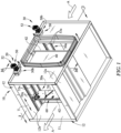
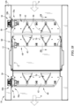
Figure 1 is a bottom perspective view a portion of the air handling system with the access door removed illustrating an embodiment of one or more scan assemblies; -
Figure 2 is a top perspective view the air handling system ofFig. 1 with a portion of an exterior portion exploded away from the scan assembly; -
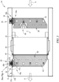
Figure 3 is a sectional view of the embodiment ofFig. 1 taken along line 3-3 -
Figure 4 is a close up sectional view of the embodiment ofFig. 3 ; -
Figure 5 is a perspective view of a first scan assembly and a second scan assembly ofFig. 1 ; -
Figure 6 is an exploded view of the first scan assembly ofFig. 5 ; -
Figure 7 is a perspective view of a portion or three-sided member of an embodiment of a scan probe; -
Figure 8 is an upstream inlet view of the scan probe portion ofFig. 7 ; -
Figure 9 is a side view of the scan probe portion ofFig. 7 ; -
Figure 10 is a downstream outlet view of the scan probe portion ofFig. 7 ; -
Figure 11 is a sectional view of the scan probe portion ofFig. 9 taken along line 11-11; -
Figure 12 is a perspective view of an embodiment of an interior magnetic array of a track system interior portion and a perspective view of an embodiment of an exterior magnetic array of the track system exterior portion; -
Figure 13 is a side view of the interior magnetic array and the exterior magnetic array ofFig. 12 illustrating relative alignment relative to each other and arrows indicating magnetic pole orientation of individual magnets; -
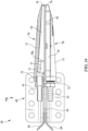
Figure 14 is a sectional view of an embodiment of a depending arm positioning a plurality of scan probes ofFig. 5 taken along line 14-14; -
Figure 15 is a sectional view of the depending arm positioning a plurality of scan probes ofFig. 5 taken along line 15-15; -
Figure 16 is a sectional view of the first scan assembly installed with the air handling system ofFig. 1 taken along line 16-16; -
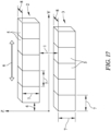
Figure 17 is a schematic of an exemplary testing configuration for the driving magnetic array and the driven magnetic array; -
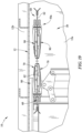
Figure 18 is a partial side sectional view of another embodiment of an air handling system illustrating a validation or measurement configuration of a probe assembly, with the filter removed from the air passageway; -
Figure 19 is a sectional view ofFig. 18 taken along line 19-19; -
Figure 20A is an exploded perspective view of another embodiment of an interior magnetic array of a track system interior portion and the exterior magnetic array of the track system exterior portion illustrating an embodiment of a cover; -
Figure 20B is an assembled view ofFig. 20A ; -
Figure 20C is a sectional view ofFig. 20B taken alongline 20C-20C; -
Figure 21A is an exploded perspective view of another embodiment of an interior magnetic array of a track system interior portion and the exterior magnetic array of the track system exterior portion illustrating another embodiment of a cover; -
Figure 21B is an assembled view ofFig. 21A ; and -
Figure 21C is a sectional view ofFig. 21B taken alongline 21C-21C. - Numerous variations and modifications will be apparent to one of ordinary skill in the art, as will become apparent from the description below. Therefore, the invention is not limited to the specific implementations discussed herein but is only limited by the scope of the claims.
- As illustrated in the Figures, one or
more scan assemblies air handling system 10 to test, monitor, and/or introduce material to one ormore filters 40 within the air flow A of theair passageway 11. Thehousing 12 of theair handling system 10 may have anexterior side 12a and aninterior side 12b. Theinterior side 12b may define theair passageway 11 having the air flow A passing therethrough. A sealed access door, removed for clarity in the Figures, may provide access into the passageway to access the one or more filter areas adapted to receive or defining the replaceable filter media or filter 40 (e.g. remove, install, repair, etc.). Moreover, although not shown, one or more dampers may be used within the housing upstream and/or downstream of the filters position. The one ormore filters 40 may be a variety of constructions, quantities, and materials with a variety of characteristics (e.g. a HEPA filter, ePTFE). The filter includes anupstream face 42 and an opposingdownstream face 44. - The
scan assembly interior portion 50a and anexterior portion 50b of atrack system 50 through the housing 12 (e.g. one or more walls or top wall). Thetrack system 50 may have aninterior portion 50a that can be positioned traverse to or laterally (e.g. transverse, linear, or direction of travel) relative to the direction of air flow A. The direction of travel or transverse direction T is shown more clearly inFig. 2 . Theinterior portion 50a, within the sealed interior side12b, is actuated via theexterior portion 50b outside of or on theexterior side 12a of the housing. Theinterior portion 50a may be slidingly moved to a variety of positions along the transverse or travel direction without mechanical contact from theexterior portion 50b thereby maintaining a sealed or unbroken interior side or air passageway. Thescan assembly interior side 12b of thehousing 12 during operation and/or testing. Thescan assembly air handling system 10. Although thescan assembly track systems 50 orscan assemblies - In the implementation shown, the
exterior portion 50b andinterior portion 50a of thetrack system 50 includes a plurality of magnets. The plurality of magnets of one or more corresponding portions may be arranged in anarray interior portions exterior portion 50b drives theinterior portion 50a along the transverse direction T. In the one embodiment shown more clearly inFigs. 12 and 13 , eachmagnet 51 may be a rectangular shape and positioned as plurality of adjacent magnets in a horizontal plane. Moreover, eachmagnet 51 may have an embodiment of a polarity and orientation relative to anotheradjacent magnet 51 and/orportion Fig. 13 , theinside magnet array 51a includes one embodiment of the magnetic array polarity/direction or magnetic pole orientation ofindividual magnets 51. Moreover, theexterior magnet array 51b includes one embodiment of the magnetic array polarity/direction or magnetic pole orientation ofindividual magnets 51. Moreover, as shown in the Figures, eachelongated magnet 51 of thecorresponding array magnetic array 51a and the exteriormagnetic array 51b may be a N45SH magnet material with a magnetic coating Ni-Cu-Ni. Eacharray backing plate 51c made of a SS304 material. In various embodiments, the mounting bolt pattern of thebacking plates 51c may be different such that the particular magnetic arrays are keyed to either the interior portion or exterior portion. In some embodiments, thearrays corresponding backing plate 51c using a 3M DP-420 or equivalent. Instead of or in combination with the adhesive, one or more mechanical retaining devices or fasteners (e.g. covers and/or screws) may be used to attach the one or more magnet arrays (e.g. 51a and/or 51b) to thebacking plate 51c, respectively. These one or more retaining devices may be made of a metal, plastic, and/or other low magnetic material in some embodiments. As shown more clearly inFig. 4 , the exteriormagnetic array 51b may be offset or spaced from the interiormagnetic array 51a to create a gap or spacing G to operably control the magnetic forces/flux or relative reactions or transfer between theinterior portion 50a and theexterior portion 50b. In the one embodiment shown, the gap G may be about 0.2 inches. The gap G of the non-magnetic portion of the magnetic circuit separates the inwardly facing surfaces of thearrays housing 12 as shown, additional nonmagnetic materials may be used therebetween. By using the air within the gap, in some embodiments, friction may be reduced. The gap or gap range may also provide space for a shim(s) on the exterior/interior portions for fine tuning of the magnet gap or range of the gap if necessary. The magnet arrays or configuration may be a variety of materials, quantities, positions, shapes, sizes, and constructions and still be within the scope of the invention. For example, one or more programmable magnets may be used. - In some implementations, the one or more retaining devices may be a cover or
plate backing plate 51c, respectively. As shown in the one embodiment inFigs. 20A-20C and another embodiment inFigs. 21A-21C , the retaining device may be acover magnetic arrays magnetic arrays cover more covers backing plate 51c. Thecover backing plate 51c. One or more fasteners and/or adhesive may attach the cover (e.g. through the flange apertures) to the backing plate (e.g. backing plate apertures). In the one embodiment shown inFigs. 21A-21C , at least onecover 151d may include one or more recesses (e.g. hex shaped) adjacent the apertures within the flanges 151db to receive one or more nuts 151dc (e.g. hex shaped) to attach thecover 151d to thebacking plate 51c via one or more fasteners (e.g. bolts). Moreover, thecover cover 51d shown inFigs. 20A-20C may be made of metal (e.g. low magnetic material). In other embodiments, as shown inFigs. 21A-21C , thecover 151d may be made of plastic. - An exemplary measurement test was conducted for one embodiment of the magnetic configuration, illustrating a basic strength relationship of the magnets. The conditions included: the
gap 1 between the exteriormagnetic array 2 and the interiormagnetic array 3 to be 0.2 inches, an offset 4 in the transverse direction between the arrays being 0.1 inches for the finite element analysis (FEA),individual block 5 size being 2 inch (ref 8) X 0.2 inch (ref 7) X 0.2 inch (ref. 7) (M), magnet materials EEC-N45H or EEC SmCo-33 magnet, total magnet weight for all 10 magnets without housing is about 0.22 lbs for N45H and 0.25 lbs for SmCo-33, thelinear motion direction 6 the driver orexterior array 2 mounted on a linear motor and the driven or interiormagnetic array 3 supporting a sensor structure. The exemplary configuration is shown inFig. 17 and the calculations are shown below in the chart for the drivermagnetic array 2 on the top outside and the drivenmagnetic array 3 on the bottom inside of the ventilation tube.Design Option Exterior Magnet Array Interior Magnet Array Magnetic Force along the Y axis (lbs) Magnetic Force along the Z-axis (lbs) 1 N45H N45H 22 25 2 SmCo-33 SmCo-33 16 18 3 N45H SmCo-33 19 21 Fig. 17 . The linear coupling force was found to be proportional to the magnet strength. Operating temperatures of about 50 degrees Celsius of less reduced demagnetization. The 0.2 inch gap used in the study may allow for the housing material thickness of about 0.08 inches leaving approximately 0.12 inches for manufacturing tolerances or the possibility of a thicker housing wall. While a thinner air gap increases the magnetic coupling strength, it also increases the load on the linear bearings which then increases the drag of the interior portion and exterior portion. - One implementation of the
exterior portion 50b of thetrack system 50 may be mounted above the upper/top wall of thehousing 12 in theexterior 12a. As such theinterior portion 50a of thetrack system 50 may be mounted within the interior 12b of thehousing 12 adjacent the upper/top wall in the transverse direction T of travel. In use, theexterior portion 50b may be installed, replaced, subsequently added to theair handling system 10 as an add-on or upgrade, or repaired without entering the sealedair passageway 11,housing wall 12, and/or interior12b of the housing. Theexterior portion 50b may also be transferred between a first lower portion at one location and second lower portion located at another location (e.g. locations on one or more air handling systems) to operate the corresponding location or scan assembly in some embodiments. As shown in the Figures, theexterior portion 50b may be mounted to the sidewalls and extend across the upper wall of the housing in the transverse direction T. Although theexterior portion 50b may be mounted at a single end at thehousing 12 as shown in the Figures, adjacent theactuator 52, the opposing ends may be mounted between the uprights of the sidewalls or at a variety of locations with the housing. Although not shown, in some embodiments, the exterior portion may be secured to a portion of the upper wall. It should be understood that the interior andexterior portions - In use, the
interior portion 50a may be installed, replaced, subsequently added to the air handling system as an add-on or upgrade, or repaired. In addition, thehousing 12 may be decontaminated while manipulating the interior portion. In various embodiments, the mounting bolts, mount, or fasteners may be preinstalled within the interior 12b of thehousing 12. As such, theinterior portion 50a may be installed or the air handling system upgraded with reduced field fabrication (e.g. reduced or no drilling, welding, burning, etc.) - One or
more scan assemblies air handling system 10. In the one embodiment shown, twoscan assemblies first scan assembly 20 may be positioned downstream of the filter area orair filter 40 and asecond scan assembly 30 may be positioned upstream from the filter area orair filter 40. For convenience, one embodiment of thefirst track system 50 of thefirst scan assembly 20 will be discussed in more detail. Thefirst track system 50 may be positioned downstream of the filter area orair filter 40 on thehousing 12 to translate a portion of theinterior portion 50a in the transverse direction T across thedownstream face 44 of theair filter 40 or filter area. - In the embodiment shown in the Figures, the
exterior portion 50b of thetrack system 50 may be mounted to the exterior of thehousing 12 in a variety of locations. Theexterior portion 50b drives theinterior portion 50a within the sealedair passageway 11 via the interior and exteriormagnetic array exterior portion 50b may include a rail, slide, orchannel 53b slidingly engaging the exteriormagnetic array 51b outside thehousing 12. Moreover, a magnetic drive member orcarriage 54b may mount the exteriormagnetic array 51b with thechannel 53b. Thedrive member 54b may be a self-lubricated plastic in some embodiments (e.g. PEEK or TRIBO). Thechannel 53b may be extruded stainless steel or aluminum. Theactuator 52 may translate or slide the drive member/exterior magnetic array relative to the channel. The actuator 52 advances the moveable portion of theinterior portion 50a along the length or portion thereof of thetrack system 50. Theactuator 52 may be a servo motor in some embodiments as shown, however the actuator may be pneumatic, belt driving, cable driving, portable drill, stepper motors, and/or hydraulic, etc. Although the embodiment shown of the track system 540 is motor driven or automatically driven, it should be understood that the drive member may be manually operated (e.g. push-pull device, crank assembly, etc.) in some embodiments. Further, in various embodiments, two or more scan assemblies may be operated by a single actuator and/or connected via a gear or linkage mechanism. Theexterior portion 50b may include alead screw 53 threadably engaging threads (e.g. internal) of thedrive member 54b in some embodiments. Thelead screw 53 may be coupled to theactuator 52 with asplined coupling 52b. Thedrive member 54b may be internally threaded to engage the lead screw as shown in the Figures. Anactuator face plate 52c,actuator motor connector 52d, and/or motorquick disconnect 52e may be mounted on the housing to position the exterior portion as shown more clearly inFig. 16 . This motor engagement may provide for a quick disconnect of the actuator or motor. - In some implementations, the
drive member 54b of theexterior portion 50b may include structure to position or mount the exteriormagnetic array 51b. For example, atop plate 54c and a bottom plate orspacer 54d may be positioned on corresponding upper and lower sides of thedrive member 54b. Theexterior magnet array 51b and/orbacking plate 51c may be mounted below the bottom plate54d. Thetop plate 54c may be plastic in some embodiments. Thebottom plate 54d may be plastic, stainless steel, and/or aluminum in various embodiments. Thedrive member 54b of theexterior portion 50b may position theexterior magnet array 51b from the housing 12 (e.g. 14 gage stainless steel) and/or interiormagnetic array 51a (e.g. gap G). - In some implementations, the
interior portion 50a may include one or more interior rails, tracks, orchannels 53a slidingly engaging theinterior magnet array 51a. One or more rails ortracks 53a may be secured to the interior of the upper wall of thehousing 12. As shown in the embodiment, a pair oflinear rails 53a may be used. Therails 53a may include elongated rods 53ac. Therails 53a may be stainless steel or anodized aluminum. In some embodiments, theinterior portion 50a may include acarriage block 54a positioning the interiormagnetic array 51a and/orbacking plate 51c relative to thehousing 12,exterior portion 50b, and/or exteriormagnetic array 51b (e.g. gap G) along therails 53a. Thecarriage block 54a may be aluminum in some embodiments. In some embodiments, one ormore bearing blocks 55a and/or one or more linear bearings 55ac may be used to slidingly engage therails 53a and/or rods 53ac to thecarriage block 54a. The bearing blocks 55a may be anodized aluminum with replaceable linear bearings 55ac (e.g. self-lubricated plastic or TRIBO plastic liners). The bearing blocks 55a may slidingly engage the rails and/or elongated rods along the linear direction for a desired length. - A variety of devices or structure used to sample, test, introduce material into the air handling system and/or towards the filter may be attached to the
interior portion 50a or one ormore carriage blocks 54a traveling or sliding along thelinear rails 53a within theair passageway 11. The structure may depend downwardly from thecarriage block 54a. In some embodiments, the depending structure may include one or more depending arms. In some implementations as shown, thefirst scan assembly 20 may include one or more dependingarms 60 shown in a fixed or vertical orientation relative to thecarriage 54a. Although other orientations and/or movement relative to the carriage should be understood to be within the scope of the invention. Thearms 60 may include one or more scan probes 70 to sample the air downstream of the filter area/filter 40 or from the filter (e.g. sampling). The one or more scan probes 70 may receive challenge material to calculate leaks and/or location of the leaks across thedownstream face 44 of the filter area/filter 40. A tube fitting 61 adjacent thedownstream outlet 72 of the scan probes 70 may include one or more tubes (not shown) for reading/testing samples to transfer to a variety of test equipment. In some embodiments, the arms and/or probes may be of a unitary or single piece construction (e.g. single molded piece). The arms and devices (e.g. scan probes) may be a variety of materials, quantities, positions, shapes, sizes, and constructions and still be within the scope of the invention. - Although the interior portion in the one embodiment is shown having one depending arm, it should be understood that the
interior portion 50a may include a plurality of dependingarms 60. Each arm of the interior portion may carry the same or different devices relative to another arm (e.g. one arm with scan probes and another arm with injectors/dispersion probes). Moreover, each arm may have a variety of devices (e.g. arm with both scan probes and sensors). For example, in various embodiments, the interior portion may have two depending arms each for scanning particles (e.g. the arms may be attached to the same magnet array/carriage block or different magnet arrays/carriage block). In some embodiments, the interior portion or carriage with two depending arms, one arm with scanning probes and the other arm with aerosol injectors. It should be understood that the arms depending from the interior portion or carriage block may be in a variety of positions or ordinations relative to each other and may travel along the one or more tracks in a variety of positons relative to each other (e.g. same or different rates or positions along the rail(s)). - For example, in one embodiment of an air handling system may include two HEPA filters in series, each filter may be scan tested. The system may have a first interior and exterior portion upstream of the upstream or first HEPA filter to inject aerosol downstream, a second interior and exterior portion downstream of the first HEPA filter and upstream of the downstream or second HEPA filter to scan test the first HEPA filter, a third interior and exterior portion downstream between the first HEPA filter and the second HEPA filter to inject test aerosol into the second HEPA filter, and a fourth interior and exterior portion downstream of the second HEPA filter to scan test the second HEPA filter. Alternatively, a single interior and exterior portion/carriage block may include a depending arm(s) with scan probes to scan test the first HEPA filter and aerosol injection nozzles to inject test aerosol into the downstream second HEPA filter.
- In one implementation as shown more clearly in
Figs. 5 and16 , a plurality of scan probes 70 may be in an overlapping arrangement along the length of the one or more dependingarms 60. Adjacent probes overlap for a distance or length D in the vertical direction. - In the one embodiment shown, the depending
arm 60 may include anelongated spine 62 mounted to thecarriage block 54a and/or interiormagnetic array 51a sliding in the transverse direction T along therails 53a. Thespine 62 may increase the strength of the depending arm and provide consistent alignment of the devices (e.g. probes, injectors, camera, sensors such as but is not limited to biological, temperature, velocity, etc., injector nozzles, etc.) attached thereto to scan or slide in the transverse direction T. Thespine 62 may include one ormore spine stiffeners 64. As shown more clearly inFigs. 6 and14 , one implementation of thespine stiffener 64 is adjacent the downstream edge and extends along a portion of the length of the spine. Thespine 62 may be made from a stainless steel in some embodiments. - The
spine 62 may be a common wall for the one or more scan probes 70. The plurality of scan probes 70 may share the elongated spine wall. Thespine 62 may define one or more walls, portions, or theinner periphery 71 of the one or more scan probes 70. In the one embodiment shown, adjacent scan probes 70 of the plurality of overlapping scan probes are positioned on opposing sides of thespine 62. The internal air passageway of thescan probe 70 may be defined by theinner periphery 71 of thescan probe 70 and/orspine 62 from theupstream inlet 74 towards thedownstream outlet 72. Thespine 62 may define a portion of theupstream inlet 74 and/ordownstream outlet 72. For example, as shown in the one embodiment, the spine defines the upstream inlet and not the downstream outlet. As more clearly shown inFigs. 7-11 , a portion of thescan probe 70 may define three sides of the internal air passageway orinner periphery 71 with thetop wall 75 andbottom wall 76 tapering towards thedownstream outlet 72. Thelateral side 77 of the three sided member may taper towards theinlet 74 and may be unparallel to the planar lateral face of thespine 62. This three sided member may be coupled to the planar lateral face of the elongated spine to form theinner periphery 71 of eachadjacent scan probe 70. - In some implementations, the scan probes 70 may be constructed to increase accuracy or sample at an air flow velocity within the scan probe more closely to the duct velocity. One or more protrusions or
dampers 78 within the internal air passageway or inner periphery of theprobe 70 may equalize the velocity at thedownstream outlet 72 of thescan probe 70 or fitting 61 to equalize the pressure entering the scan probe. The one ormore protrusions 78 may define one ormore channels 79 extending from theupstream inlet 74 towards the downstream outlet. The scan probes and spine, if used, to define the inner periphery may include thechannels 79 and/orprotrusions 78. The one ormore channels 79 may decrease in size towards thedownstream outlet 72. Thechannels 79 may be vertically positioned or stacked above adjacent channels within a vertical plane or the scan probe. Theprotrusions 78 may extend away from the inner periphery of the probe orlateral sides 77 thereof and project inwardly into the internal air passageway defined by theinner periphery 71. The one or more protrusions may extend from one or more sides of theinner periphery 71 of thescan probe 70 and/orspine 62. - In the one embodiment shown, the one or more protrusion may be one or more elongated fins or weir (e.g. continuous or intermittent) extending in the direction of air flow. The fin may extend from the
upstream inlet 74 towards thedownstream outlet 72 for a distance. In some embodiments, adistal end 78a of the fin may be spaced from thedownstream outlet 72. The fin may be orientated transverse to the horizontal plane. In the one embodiment shown, a pair ofelongated fins 78 taper towards each other in the direction of air flow towards thedownstream outlet 72 thereby narrowing thechannel 79 therebetween and the correspondingchannels 79 between adjacent tapering top andbottom walls lateral sides 77 of the scan probe. The lateral sides 77 of the probe between the top andbottom walls elongated fins 78 may increase in width between thelateral sides 77 of the scan probe. If the spine is used, theelongated fin 78 may extend from thelateral side 77 of the three sided member to the substantially planar lateral surface of theelongated spine 62. The one ormore protrusions 78 may extend inwardly from the spine and/or remaining portion of the scan probe. It should be understood the channels and protrusions shown in one embodiment in the Figures may be a variety of quantities, shapes, sizes, materials, orientations, and construction and still be within the scope of the invention. - As shown in the one implementation of the
second scan assembly 30 positioned upstream of the filter area orfilter 40, a variety of devices or structure may be attached to the interior portion or one or more carriage blocks traveling along the linear rails within the air passageway. Theinterior portion 50a of thetrack system 50 includes one ormore injectors 90. The dependingarm 60 orspine 62, if used, may include one ormore injectors 90 extending along the spine (e.g. overlapping adjacent injectors by a length or distance D). The one or more injectors may slide between one or more lateral positions across theupstream face 42 of the filter in the transverse direction T. The injector(s) 90 may introduce aerosol, decontamination, or other material with increased accuracy and volume control to minimize the loaded of the filter when testing or introducing one or more materials towards the filter from the upstream position. For example, in some implementations the reduction of the amount of test aerosol used may benefit ePTFE filter applications. The test aerosol injected downstream from thescan assembly 30 or injectors 90 (e.g. aerosol injection nozzles) may create a uniform test aerosol profile discharged at the inlet to the filter. Typical systems utilized increased distance and turbulence generating structure (e.g. one or more baffles) to create uniformity at the filter, the scan assembly and/orinjectors 90 may reduce the distance in front of the filter which may correspondingly allow a reduction in size (e.g. length) of thesystem 10. - It should be understood that the devices attached to the interior portion or depending arm(s) may be a variety of constructions, quantities, shapes, sizes, and positions within the housing and still be within the scope of the invention. For example, one or more visual devices or cameras (e.g. IR, thermal, etc.) may be attached to the
interior portion 50a of one ormore track systems 50. In various embodiments, one or more nozzles may be used. In addition in some embodiments, one or more sensors may be used for temperature, velocity, biological, etc. analysis. Moreover, for example, biological, decontamination, patching/repair (e.g. liquid), and/or fluorescent materials or the like may be introduced upstream and/or downstream of the filter (e.g. onto the surface of the filter) or at other locations within the air handling system. A thermal response, color spectrums, illumination of materials, and sterilization within the air handling system or filter may be desired to be controlled by the scan assembly. - A control system may be used to position the track system of one or more scan assemblies. The control system may control the rate of travel, one or more positions, direction of travel, monitoring, and/or introducing of materials of one or more scan assemblies. For example, the rate of travel and position of the first scan assembly and/or scan probes may be coordinated with the rate of travel and position of the first assembly introducing aerosol via the injectors. In some embodiments, the rate of travel of two or more scan assemblies may be different or the same.
- In some implementations, as shown in
Figs. 18 and19 , theair handling system 10 may include one ormore probe assemblies 80 for validation and/or measurement of upstream aerosol challenge characteristics. Theprobe assembly 80 may be in a fixed position and laterally outside the outer periphery of thefront face 42 of thefilter 40. This fixed location may be a non-obtrusive location within the air passageway. A plurality of scan probes may be fixed in place to receive aerosol upstream of the one or more filters being tested and in alignment with the individual aerosol injection nozzles in their position (e.g. stationary parked). In the one embodiment shown, theprobe assembly 80 may be a dependingarm 60 with one or more scan probes 70. Theprobe assembly 80 may be directly coupled to the particle counter. Thescan assembly 30 may be positioned (e.g. home position) in fluid communication with thedownstream probe assembly 80. For example, one ormore injectors 90 may be in fluid communication with one or more scan probes 70. Theprobe assembly 80 may be used for measurement and validation of the upstream aerosol challenging conditions emitted from thescan assembly 30. The probe assembly and validation/measurement may allow for particle counts that are more accurate and repeatable for a particular design condition of the application. The validation may be completed without entering or contaminating the sealedair passageway 11. It should be understood that other materials or characteristics of air flow or conditions within the housing (e.g. decontamination agents, thermal, velocity, etc.) may be validated or measured with the probe assembly. The probe assembly and probes/sensors may be a variety of materials, quantities, positions, shapes, sizes, and constructions and still be within the scope of the invention. - Conducting the upstream count verification of the probe assembly may involve connecting one of the stationary corresponding receptor probes to the particle counter and initiating the flow of test aerosol through the corresponding aerosol injection nozzle for an appropriate period of time and/or cycles. Once completed, the system may be manually or automatically cycled to the next corresponding set of receptor probes and aerosol injecting nozzles and the calculation repeated. Once all the probe/nozzle assemblies have been tested, the average of the statistically valid values is determined and set as the Cu or upstream count.
Claims (18)
- An apparatus for introducing material to or monitoring characteristics of an air filter (40) within an air handling system (10), comprising:a housing (12) having an exterior side (12a) and an interior side (12b), wherein the interior side (12a) defining an air passageway (11) adapted to form a part of the air handling system (10) having an air flow (A) passing therethrough;one or more filter areas (40) positioned within the interior side (12b) of the housing (12) adapted to receive a replaceable filter media (40) with a downstream face (44) and an opposing upstream face (42);a first scan assembly (20) positioned at least one of upstream and downstream of the one or more filter areas (40) , wherein the first scan assembly (20) having a track system (50) directing one or more depending arms (60) within the air passageway (11) in a transverse direction (T) to the air flow (A);the track system (50) having an exterior portion (50b) positioned on the exterior side (12a) of the housing (12) and an interior portion (50a) positioned on the interior side (12b) of the housing (12); whereinthe interior portion (50a) includes a carriage (54b) and the one or more depending arms (60) slidingly engaging one or more first rails (53a); characterized in thatthe interior portion (50a) includes an interior magnetic array (51a), andthe exterior portion (50b) includes a drive member (54b) and an exterior magnetic array (51b) slidingly engaging one or more second rails (53a), and an actuator (52), wherein the actuator (52) slides the drive member (54b) and the exterior magnetic array (51b) on the one or more second rails (53a) along the exterior side (12a) of the housing (12) and correspondingly slides the carriage (54b), the interior magnetic array (51a), and one or more depending arms (60) on the one or more first rails (53a) in the transverse direction along the interior side (12a) of the housing (12).
- The apparatus of claim 1 includes the first scan assembly (20) positioned downstream of the one or more filter areas (40).
- The apparatus of claim 1 further comprising a second scan assembly (30) positioned on the other of the at least one of upstream and downstream position of the first scan assembly (20).
- The apparatus of claim 3 wherein the first scan assembly (20) has a first rate of travel for the drive member (54b) along the transverse direction (T) and the second scan assembly (30) has a second rate of travel for the drive member (54b) along the transverse direction (T).
- The apparatus of claim 4 wherein the first rate of travel and the second rate of travel is the same or different from each other.
- The apparatus of claim 1 wherein the one or more first rails (53a) comprises a pair of linear rails (53a) parallel spaced from each other and in sliding engagement with the carriage (54b).
- The apparatus of claim 6 wherein the interior portion (50a) of the track system (50) further comprises one or more linear bearings (55ac) between the pair of linear rails (53a) and the carriage (54b).
- The apparatus of claim 1 wherein the exterior portion (50b) of the track system (50) further comprises a lead screw (53) driven by the actuator (52), the lead screw (53) slides the drive member (54b) along the one or more second rails (53a).
- The apparatus of claim 1 wherein the drive member (54b) threadably engages the lead screw (53).
- The apparatus of claim 1 wherein the interior magnetic array (51a) and the exterior magnetic array (51b) are spaced from each other by the track system (50) to provide a gap (G) therebetween.
- The apparatus of claim 10 wherein each one of the interior magnetic array (51a) and the exterior magnetic array (51b) includes a plurality of elongated magnets (51) arranged perpendicular to the transverse direction (T) relative to the air flow (A).
- The apparatus of claim 1 wherein the actuator (52) is a servo motor.
- The apparatus of claim 1 wherein the one or more depending arms (60) of the interior portion (50a) of the track system (50) further comprises one or more devices.
- The apparatus of claim 13 wherein the one or more devices are at least one of a scan probe, a camera, a nozzle, a sensor, and an injector (90).
- The apparatus of claim 1 wherein the one or more depending arms (60) comprises a spine (62) defining a portion of one or more overlapping scan probes extending along a length of the spine (62).
- The apparatus of claim 1 further comprising a fixed probe assembly in fluid communication with one or more injectors (90) to validate test aerosol from the first scan assembly (20) positioned upstream of the one or more filter areas (40).
- The apparatus of claim 1, whereinthe first scan assembly (20) is positioned upstream of the one or more filter areas; and whereinthe one or more depending arms (60) of the interior portion (50a) of the track system (50) further comprises one or more injectors (90) directing at least one of a decontamination agent and an aerosol downstream towards the one or more filter areas (40).
- The apparatus of claim 17 wherein at least one of the interior portion (50a) and the exterior portion (50b) includes a cover (51d) attaching the interior magnetic array (51a) and the exterior magnetic array (51b) to a backing plate (51c), respectively.
Applications Claiming Priority (2)
| Application Number | Priority Date | Filing Date | Title |
|---|---|---|---|
| US201862728544P | 2018-09-07 | 2018-09-07 | |
| PCT/US2019/049973 WO2020051467A1 (en) | 2018-09-07 | 2019-09-06 | Filter testing apparatus and method |
Publications (2)
| Publication Number | Publication Date |
|---|---|
| EP3847400A1 EP3847400A1 (en) | 2021-07-14 |
| EP3847400B1 true EP3847400B1 (en) | 2025-03-19 |
Family
ID=68000114
Family Applications (1)
| Application Number | Title | Priority Date | Filing Date |
|---|---|---|---|
| EP19773274.6A Active EP3847400B1 (en) | 2018-09-07 | 2019-09-06 | Filter testing apparatus and method |
Country Status (5)
| Country | Link |
|---|---|
| US (2) | US11181461B2 (en) |
| EP (1) | EP3847400B1 (en) |
| CN (1) | CN112673214B (en) |
| ES (1) | ES3027416T3 (en) |
| WO (1) | WO2020051467A1 (en) |
Families Citing this family (6)
| Publication number | Priority date | Publication date | Assignee | Title |
|---|---|---|---|---|
| US10751659B2 (en) * | 2018-07-31 | 2020-08-25 | Applied Medical Technologies, Inc. | Leakage detection for installed filters of a multi-filter containment enclosure apparatus |
| ES3027416T3 (en) | 2018-09-07 | 2025-06-13 | American Air Filter Company Inc | Filter testing apparatus and method |
| KR102342446B1 (en) * | 2018-10-18 | 2021-12-22 | 주식회사 엘지화학 | Method of detecting defection of seperation memebrane element and apparatus of detecting defection of seperation memebrane element |
| CN113384964B (en) * | 2021-07-01 | 2022-06-28 | 康斐尔过滤设备(太仓)有限公司 | Filter |
| JP7545941B2 (en) * | 2021-09-07 | 2024-09-05 | 株式会社日立産機システム | Air Purifying Negative Pressure Device |
| JP7759354B2 (en) * | 2023-01-30 | 2025-10-23 | 日本碍子株式会社 | Inspection device and inspection method for columnar honeycomb filters |
Family Cites Families (86)
| Publication number | Priority date | Publication date | Assignee | Title |
|---|---|---|---|---|
| US2898485A (en) | 1957-09-17 | 1959-08-04 | Sperry Rand Corp Ford Instr Co | Magnetic clutch |
| US3707869A (en) * | 1971-06-09 | 1973-01-02 | Atomic Energy Commission | Airborne isokinetic sampler |
| US3765225A (en) | 1972-10-30 | 1973-10-16 | American Air Filter Co | Carbon filter leak detector |
| US4055075A (en) * | 1976-04-08 | 1977-10-25 | Flanders Filters, Inc. | Method and apparatus for the leak testing of filters |
| US4184090A (en) | 1977-10-13 | 1980-01-15 | Nova Research Foundation Corporation | Rotary magnetic isolation coupling |
| US4277707A (en) | 1978-04-24 | 1981-07-07 | The Garrett Corporation | High speed magnetic coupling |
| DE3027351A1 (en) | 1979-07-19 | 1981-02-12 | Tetsuichi Imai | Permanent magnet operated linear actuator for valve - has operating plunger inside non magnetic sleeve and magnet movable on outside |
| US4324568A (en) | 1980-08-11 | 1982-04-13 | Flanders Filters, Inc. | Method and apparatus for the leak testing of filters |
| USRE31952E (en) * | 1980-08-11 | 1985-07-23 | Flanders Filters, Inc. | Method and apparatus for the leak testing of filters |
| US4548536A (en) * | 1981-11-27 | 1985-10-22 | Toyoda Koki Kabushiki Kaisha | Working apparatus with track following motion |
| US4494403A (en) * | 1982-07-14 | 1985-01-22 | Flanders Filters, Inc. | Filter testing apparatus and method |
| US4515007A (en) * | 1983-01-04 | 1985-05-07 | The United States Of America As Represented By The United States Department Of Energy | Method of and apparatus for testing the integrity of filters |
| US4641065A (en) | 1984-05-16 | 1987-02-03 | Toyota Shatai Kabushiki Kaisha | Moving coil type linear motor |
| IE56166B1 (en) | 1985-02-15 | 1991-05-08 | Tekscan Ltd | Manipulator means |
| US4901578A (en) | 1988-05-20 | 1990-02-20 | Westinghouse Electric Corp. | Probe carrier drive assembly |
| US4893980A (en) | 1988-12-19 | 1990-01-16 | Huntington Mechanical Laboratories, Inc. | Device for moving objects within a sealed chamber |
| US5388086A (en) | 1989-06-13 | 1995-02-07 | Kabushiki Kaisha Toshiba | Electro-magnetic actuator for driving an objective lens |
| US5105932A (en) | 1990-03-09 | 1992-04-21 | Bryson Iii Charles E | Linear and rotary positioning device |
| JP2929390B2 (en) | 1990-07-20 | 1999-08-03 | 日本無機株式会社 | Air filter leak test method and apparatus |
| US5224585A (en) | 1992-04-10 | 1993-07-06 | Brigham & Women's Hospital | Carrier for coded containers |
| US5415483A (en) | 1993-08-20 | 1995-05-16 | Tooling Research, Inc. | Sealed linear positioning apparatus |
| JP3305094B2 (en) * | 1994-03-01 | 2002-07-22 | 塩野義製薬株式会社 | Dust-proof filter leak detector |
| JPH08275500A (en) | 1995-03-31 | 1996-10-18 | Minolta Co Ltd | Linear motor |
| US5514925A (en) | 1995-08-17 | 1996-05-07 | Thermionics Northwest, Inc. | Magnetic feedthrough manipulator |
| US5980193A (en) | 1996-09-18 | 1999-11-09 | Magnetic Bearing Technologies, Inc. | Magnetically levitated robot and method of increasing levitation force |
| US6206176B1 (en) | 1998-05-20 | 2001-03-27 | Applied Komatsu Technology, Inc. | Substrate transfer shuttle having a magnetic drive |
| US6453257B1 (en) * | 1998-12-18 | 2002-09-17 | Larson Testing Laboratories | Apparatus for testing the ability of a filter to filter contaminants |
| DE19923502C1 (en) | 1999-05-21 | 2001-03-15 | Krantz Tkt Gmbh | Method and device for determining the degree of separation of a filter arrangement in operation |
| US6308818B1 (en) | 1999-08-02 | 2001-10-30 | Asyst Technologies, Inc. | Transport system with integrated transport carrier and directors |
| JP4423627B2 (en) | 1999-10-07 | 2010-03-03 | ニッタ株式会社 | Clean room air filter leak inspection system |
| WO2001068220A1 (en) * | 2000-03-15 | 2001-09-20 | Mott Metallurgical Corporation | Filter system and method of operation |
| US6712907B1 (en) | 2000-06-23 | 2004-03-30 | Novellus Systems, Inc. | Magnetically coupled linear servo-drive mechanism |
| US20030063687A1 (en) * | 2001-09-29 | 2003-04-03 | Kim Yong-Yil | Linear motor |
| EP1515100A4 (en) | 2002-06-03 | 2006-09-20 | Sankyo Seiki Seisakusho Kk | Clean assembling module device, production system formed with the module, industrial robot, and pollution spred prevention system |
| EP1431680B1 (en) * | 2002-12-21 | 2007-04-18 | Seven-Air Gebr. Meyer AG | Clamping device for mounting filter frames on a grid system |
| US7439735B2 (en) | 2003-01-07 | 2008-10-21 | Stoneridge Control Devices, Inc. | Rail activated position sensor |
| US7010960B1 (en) | 2003-10-10 | 2006-03-14 | Grantham James I | Scan device and method for testing filters for leaks |
| DE10360434B4 (en) | 2003-12-22 | 2006-12-07 | Samson Ag | Arrangement, position sensor, device for regulating, driving and method for detecting the position of a drivable component |
| US7028831B2 (en) | 2004-03-05 | 2006-04-18 | Beckman Coulter, Inc. | Magnetic specimen-transport system for automated clinical instrument |
| US7210363B2 (en) * | 2004-08-04 | 2007-05-01 | Camfil Farr, Inc. | Scan testable filter housing assembly for exhaust applications |
| JP4443350B2 (en) * | 2004-08-27 | 2010-03-31 | 株式会社大気社 | Air conditioning equipment |
| US7658787B2 (en) | 2005-04-28 | 2010-02-09 | Camfil Farr, Inc. | Exhaust filter module with mechanically positionable scan probe |
| EP1912717B1 (en) | 2005-08-09 | 2016-08-24 | Camfil USA, Inc. | Integrated containment system |
| CN101297187B (en) * | 2005-10-24 | 2013-03-27 | 肯非法尔公司 | Method and apparatus for V-bank filter bed scanning |
| CA2641998A1 (en) * | 2006-03-14 | 2007-09-20 | Camfil Ab | Air filter housing with means for measuring particle concentration |
| US7997300B1 (en) * | 2006-04-11 | 2011-08-16 | The United States Of America As Represented By The Secretary Of The Army | Aerosol inlet flow modulator |
| FR2905700B1 (en) | 2006-09-08 | 2008-11-14 | Arkema France | HIGH PERFORMANCE AUTOADHERENT POWDER WITHOUT ADHESION PROMOTER BASED ON POLYAMIDE |
| CA2696240C (en) | 2007-06-29 | 2016-03-15 | Camfil Farr, Inc. | Method and apparatus for in-situ testing of filtration systems |
| DE102008008804A1 (en) | 2008-02-12 | 2009-08-13 | Caverion Gmbh | Method and device for determining the degree of separation or for carrying out a leak test in a filter arrangement |
| GB0812903D0 (en) | 2008-07-15 | 2008-08-20 | Rota Eng Ltd | Linear actuator and position sensing apparatus therefor |
| IT1390944B1 (en) | 2008-08-04 | 2011-10-27 | Scuola Superiore Di Studi Universitari E Di Perfez | PERMANENT MAGNET ACTUATOR FOR ADAPTIVE TYPE IMPLEMENTATION |
| JP5020206B2 (en) * | 2008-09-17 | 2012-09-05 | 三菱電機株式会社 | Air filter, air filter cleaning device and air conditioner using the same |
| US8408046B2 (en) | 2008-11-13 | 2013-04-02 | Zhonglin Xu | System and method for in line in situ validation of exhaust filters |
| ATE544061T1 (en) | 2008-11-26 | 2012-02-15 | Yit Germany Gmbh | METHOD AND DEVICE FOR DETERMINING THE DEGREE OF SEPARATION AND/OR FOR PERFORMING A LEAK TEST IN A FILTER ARRANGEMENT |
| TWI395938B (en) * | 2008-12-22 | 2013-05-11 | Taiwan Textile Res Inst | Gas mixing apparatus |
| GB2468301B (en) | 2009-03-03 | 2013-06-12 | Jd7 Ltd | Water mains inspection and servicing |
| US8210056B2 (en) * | 2009-04-20 | 2012-07-03 | General Electric Company | Air filtration sampling point adaptor |
| US8372186B2 (en) * | 2009-08-14 | 2013-02-12 | Gregory J. Dobbyn | Ductless fume hood gas monitoring and detection system |
| US8221681B2 (en) * | 2009-08-21 | 2012-07-17 | Camfil Farr, Inc. | Method and apparatus for decontamination of tubing |
| CN101711935B (en) * | 2009-10-19 | 2011-12-07 | 中国人民解放军军事医学科学院卫生装备研究所 | High-efficiency air filtering unit |
| TWI405961B (en) * | 2009-11-10 | 2013-08-21 | Taiwan Textile Res Inst | Air filter leak inspection method |
| US20120024694A1 (en) | 2010-07-29 | 2012-02-02 | Tango Systems, Inc. | Triangular Scanning Magnet in Sputtering Tool Moving Over Larger Triangular Target |
| US9266068B2 (en) | 2010-11-08 | 2016-02-23 | American Air Filter Company, Inc. | Aerosol generator for EPTFE filter testing and method of use |
| TWI401112B (en) | 2010-12-08 | 2013-07-11 | Taiwan Textile Res Inst | Filter leak inspection apparatus and filter leak inspection method |
| US9772271B2 (en) * | 2012-06-21 | 2017-09-26 | Hamilton Associates, Inc. | Apparatus for testing a filter |
| EP2885624A4 (en) | 2012-08-20 | 2016-04-20 | Camfil Usa Inc | ALTERNATE ADMISSION ORIFICE ZONE TEST APPARATUS |
| CN103962361B (en) | 2014-05-05 | 2016-10-05 | 苏州市金燕净化设备工程有限公司 | Scanning leak detection high-efficiency negative-pressure exhaust hood |
| CN106796041B (en) * | 2014-05-06 | 2020-08-28 | 捷通国际有限公司 | air handling system |
| US20160030871A1 (en) | 2014-08-04 | 2016-02-04 | Camfil Usa, Inc. | Filter with magnetic seal |
| CN106660634B (en) | 2014-09-05 | 2019-12-13 | 塞尔有限责任公司 | Trolley arrangements for galleys in vehicles, especially aircraft |
| US20160096135A1 (en) | 2014-10-03 | 2016-04-07 | Camfil Usa, Inc. | Door assembly with scanning mechanism, and containment system with same |
| US10006848B2 (en) * | 2014-10-03 | 2018-06-26 | Camfil Usa, Inc. | Containment housing with integrated test aerosol injection and sampling |
| WO2016057266A1 (en) * | 2014-10-05 | 2016-04-14 | Camfil Usa, Inc. | Non-intrusive filter scanning |
| US10357733B2 (en) * | 2014-11-13 | 2019-07-23 | Cts Corporation | Filter retentate removal system and method |
| US10247434B2 (en) * | 2015-01-19 | 2019-04-02 | Lennox Industries Inc. | HVAC system and an HVAC controller configured to operate the HVAC system based on air pollutant data and user comfort |
| CN106322540A (en) * | 2015-06-15 | 2017-01-11 | 山东耀通节能环保科技股份有限公司 | An indoor and outdoor dual-mode air purifying system with a sliding door |
| CN105135530A (en) * | 2015-09-23 | 2015-12-09 | 哈尔滨宇光环保节能科技发展有限公司 | Intelligent air purifier with warning function and purifying method |
| CN205678777U (en) * | 2016-02-19 | 2016-11-09 | 深圳市康弘环保技术有限公司 | Air purifier |
| CN207622931U (en) * | 2016-06-15 | 2018-07-17 | 卡菲尔有限公司 | Scanning device, scanning means and filter housing |
| CA3030245C (en) * | 2016-08-01 | 2024-02-06 | Curium Us Llc | Automated hepa filter integrity testing |
| JP6803607B2 (en) * | 2016-11-16 | 2020-12-23 | 株式会社エアレックス | Leak inspection support device and leak inspection method using this |
| US10578521B1 (en) * | 2017-05-10 | 2020-03-03 | American Air Filter Company, Inc. | Sealed automatic filter scanning system |
| CN107166557B (en) * | 2017-07-06 | 2018-07-03 | 曹嘉洋 | Efficient Displacement Air Purifier Based on Fixed Space 3D Scanning Technology |
| CN108180592B (en) * | 2017-12-27 | 2020-04-24 | 昆山斯莱姆节能科技有限公司 | Through-wall purification ventilation pipe with induced draft fan |
| US10751659B2 (en) * | 2018-07-31 | 2020-08-25 | Applied Medical Technologies, Inc. | Leakage detection for installed filters of a multi-filter containment enclosure apparatus |
| ES3027416T3 (en) | 2018-09-07 | 2025-06-13 | American Air Filter Company Inc | Filter testing apparatus and method |
-
2019
- 2019-09-06 ES ES19773274T patent/ES3027416T3/en active Active
- 2019-09-06 CN CN201980058380.5A patent/CN112673214B/en active Active
- 2019-09-06 EP EP19773274.6A patent/EP3847400B1/en active Active
- 2019-09-06 US US16/562,960 patent/US11181461B2/en active Active
- 2019-09-06 WO PCT/US2019/049973 patent/WO2020051467A1/en not_active Ceased
-
2021
- 2021-11-22 US US17/532,146 patent/US11692922B2/en active Active
Also Published As
| Publication number | Publication date |
|---|---|
| US11692922B2 (en) | 2023-07-04 |
| CN112673214A (en) | 2021-04-16 |
| WO2020051467A1 (en) | 2020-03-12 |
| ES3027416T3 (en) | 2025-06-13 |
| US11181461B2 (en) | 2021-11-23 |
| EP3847400A1 (en) | 2021-07-14 |
| US20200080925A1 (en) | 2020-03-12 |
| US20220074842A1 (en) | 2022-03-10 |
| CN112673214B (en) | 2023-05-12 |
Similar Documents
| Publication | Publication Date | Title |
|---|---|---|
| US11692922B2 (en) | Filter testing apparatus and method | |
| EP1912717B1 (en) | Integrated containment system | |
| US7658787B2 (en) | Exhaust filter module with mechanically positionable scan probe | |
| US12286614B2 (en) | Well plate incubator | |
| US7976794B2 (en) | Positioning device for the positioning of pipettes | |
| US20040047765A1 (en) | Automated robotic workstation and methods of operation thereof | |
| US10180384B2 (en) | Automated HEPA filter integrity testing | |
| KR101683056B1 (en) | Wind tunnel for testing filter with filter change module | |
| WO2017216316A1 (en) | A scanning device for filter leakage detection | |
| US20250332587A1 (en) | Fluid path system and sequencing system | |
| CN116052918A (en) | Neutron source shielding system and neutron photographing equipment | |
| CA2647424C (en) | Balancing means for high-speed scanning | |
| US20250367670A1 (en) | Systems and Methods for a Bench System to Support a Mass Spectrometer | |
| WO2001085088A1 (en) | Flow cytometer safety cabinet | |
| Smith et al. | A translating stage system for μ-PIV measurements surrounding the tip of a migrating semi-infinite bubble | |
| US20190151852A1 (en) | Autosampler with ultrasonic bath for handling samples and standards with suspended nanoparticles | |
| US7649183B2 (en) | Apparatus for monitoring an item for radioactive material on or associated with the item | |
| CN118962166B (en) | Biochemical analysis device | |
| CN221141736U (en) | Nucleic acid detection cartridge and cartridge mount pad | |
| CN221141740U (en) | Hydraulic cover assembly and nucleic acid detector | |
| JP6178092B2 (en) | Stage device and electron beam application device | |
| CN119197052A (en) | A cavity of vacuum drying equipment |
Legal Events
| Date | Code | Title | Description |
|---|---|---|---|
| STAA | Information on the status of an ep patent application or granted ep patent |
Free format text: STATUS: UNKNOWN |
|
| STAA | Information on the status of an ep patent application or granted ep patent |
Free format text: STATUS: THE INTERNATIONAL PUBLICATION HAS BEEN MADE |
|
| PUAI | Public reference made under article 153(3) epc to a published international application that has entered the european phase |
Free format text: ORIGINAL CODE: 0009012 |
|
| STAA | Information on the status of an ep patent application or granted ep patent |
Free format text: STATUS: REQUEST FOR EXAMINATION WAS MADE |
|
| 17P | Request for examination filed |
Effective date: 20210305 |
|
| AK | Designated contracting states |
Kind code of ref document: A1 Designated state(s): AL AT BE BG CH CY CZ DE DK EE ES FI FR GB GR HR HU IE IS IT LI LT LU LV MC MK MT NL NO PL PT RO RS SE SI SK SM TR |
|
| DAV | Request for validation of the european patent (deleted) | ||
| DAX | Request for extension of the european patent (deleted) | ||
| STAA | Information on the status of an ep patent application or granted ep patent |
Free format text: STATUS: EXAMINATION IS IN PROGRESS |
|
| 17Q | First examination report despatched |
Effective date: 20230418 |
|
| GRAP | Despatch of communication of intention to grant a patent |
Free format text: ORIGINAL CODE: EPIDOSNIGR1 |
|
| STAA | Information on the status of an ep patent application or granted ep patent |
Free format text: STATUS: GRANT OF PATENT IS INTENDED |
|
| INTG | Intention to grant announced |
Effective date: 20241028 |
|
| GRAS | Grant fee paid |
Free format text: ORIGINAL CODE: EPIDOSNIGR3 |
|
| GRAA | (expected) grant |
Free format text: ORIGINAL CODE: 0009210 |
|
| STAA | Information on the status of an ep patent application or granted ep patent |
Free format text: STATUS: THE PATENT HAS BEEN GRANTED |
|
| AK | Designated contracting states |
Kind code of ref document: B1 Designated state(s): AL AT BE BG CH CY CZ DE DK EE ES FI FR GB GR HR HU IE IS IT LI LT LU LV MC MK MT NL NO PL PT RO RS SE SI SK SM TR |
|
| REG | Reference to a national code |
Ref country code: GB Ref legal event code: FG4D |
|
| P01 | Opt-out of the competence of the unified patent court (upc) registered |
Free format text: CASE NUMBER: APP_8217/2025 Effective date: 20250218 |
|
| REG | Reference to a national code |
Ref country code: CH Ref legal event code: EP |
|
| REG | Reference to a national code |
Ref country code: DE Ref legal event code: R096 Ref document number: 602019067496 Country of ref document: DE |
|
| REG | Reference to a national code |
Ref country code: NL Ref legal event code: FP Ref country code: IE Ref legal event code: FG4D |
|
| REG | Reference to a national code |
Ref country code: ES Ref legal event code: FG2A Ref document number: 3027416 Country of ref document: ES Kind code of ref document: T3 Effective date: 20250613 |
|
| PG25 | Lapsed in a contracting state [announced via postgrant information from national office to epo] |
Ref country code: RS Free format text: LAPSE BECAUSE OF FAILURE TO SUBMIT A TRANSLATION OF THE DESCRIPTION OR TO PAY THE FEE WITHIN THE PRESCRIBED TIME-LIMIT Effective date: 20250619 |
|
| PG25 | Lapsed in a contracting state [announced via postgrant information from national office to epo] |
Ref country code: FI Free format text: LAPSE BECAUSE OF FAILURE TO SUBMIT A TRANSLATION OF THE DESCRIPTION OR TO PAY THE FEE WITHIN THE PRESCRIBED TIME-LIMIT Effective date: 20250319 |
|
| REG | Reference to a national code |
Ref country code: LT Ref legal event code: MG9D |
|
| PG25 | Lapsed in a contracting state [announced via postgrant information from national office to epo] |
Ref country code: NO Free format text: LAPSE BECAUSE OF FAILURE TO SUBMIT A TRANSLATION OF THE DESCRIPTION OR TO PAY THE FEE WITHIN THE PRESCRIBED TIME-LIMIT Effective date: 20250619 |
|
| PG25 | Lapsed in a contracting state [announced via postgrant information from national office to epo] |
Ref country code: HR Free format text: LAPSE BECAUSE OF FAILURE TO SUBMIT A TRANSLATION OF THE DESCRIPTION OR TO PAY THE FEE WITHIN THE PRESCRIBED TIME-LIMIT Effective date: 20250319 |
|
| PG25 | Lapsed in a contracting state [announced via postgrant information from national office to epo] |
Ref country code: LV Free format text: LAPSE BECAUSE OF FAILURE TO SUBMIT A TRANSLATION OF THE DESCRIPTION OR TO PAY THE FEE WITHIN THE PRESCRIBED TIME-LIMIT Effective date: 20250319 |
|
| PG25 | Lapsed in a contracting state [announced via postgrant information from national office to epo] |
Ref country code: BG Free format text: LAPSE BECAUSE OF FAILURE TO SUBMIT A TRANSLATION OF THE DESCRIPTION OR TO PAY THE FEE WITHIN THE PRESCRIBED TIME-LIMIT Effective date: 20250319 Ref country code: GR Free format text: LAPSE BECAUSE OF FAILURE TO SUBMIT A TRANSLATION OF THE DESCRIPTION OR TO PAY THE FEE WITHIN THE PRESCRIBED TIME-LIMIT Effective date: 20250620 |
|
| REG | Reference to a national code |
Ref country code: AT Ref legal event code: MK05 Ref document number: 1777235 Country of ref document: AT Kind code of ref document: T Effective date: 20250319 |
|
| PG25 | Lapsed in a contracting state [announced via postgrant information from national office to epo] |
Ref country code: SE Free format text: LAPSE BECAUSE OF FAILURE TO SUBMIT A TRANSLATION OF THE DESCRIPTION OR TO PAY THE FEE WITHIN THE PRESCRIBED TIME-LIMIT Effective date: 20250319 |
|
| PGFP | Annual fee paid to national office [announced via postgrant information from national office to epo] |
Ref country code: NL Payment date: 20250820 Year of fee payment: 7 |
|
| PG25 | Lapsed in a contracting state [announced via postgrant information from national office to epo] |
Ref country code: SM Free format text: LAPSE BECAUSE OF FAILURE TO SUBMIT A TRANSLATION OF THE DESCRIPTION OR TO PAY THE FEE WITHIN THE PRESCRIBED TIME-LIMIT Effective date: 20250319 |
|
| PG25 | Lapsed in a contracting state [announced via postgrant information from national office to epo] |
Ref country code: PT Free format text: LAPSE BECAUSE OF FAILURE TO SUBMIT A TRANSLATION OF THE DESCRIPTION OR TO PAY THE FEE WITHIN THE PRESCRIBED TIME-LIMIT Effective date: 20250721 |
|
| PGFP | Annual fee paid to national office [announced via postgrant information from national office to epo] |
Ref country code: DE Payment date: 20250820 Year of fee payment: 7 |
|
| PG25 | Lapsed in a contracting state [announced via postgrant information from national office to epo] |
Ref country code: PL Free format text: LAPSE BECAUSE OF FAILURE TO SUBMIT A TRANSLATION OF THE DESCRIPTION OR TO PAY THE FEE WITHIN THE PRESCRIBED TIME-LIMIT Effective date: 20250319 |
|
| PGFP | Annual fee paid to national office [announced via postgrant information from national office to epo] |
Ref country code: IT Payment date: 20250820 Year of fee payment: 7 |
|
| PGFP | Annual fee paid to national office [announced via postgrant information from national office to epo] |
Ref country code: GB Payment date: 20250820 Year of fee payment: 7 |
|
| PG25 | Lapsed in a contracting state [announced via postgrant information from national office to epo] |
Ref country code: AT Free format text: LAPSE BECAUSE OF FAILURE TO SUBMIT A TRANSLATION OF THE DESCRIPTION OR TO PAY THE FEE WITHIN THE PRESCRIBED TIME-LIMIT Effective date: 20250319 |
|
| PGFP | Annual fee paid to national office [announced via postgrant information from national office to epo] |
Ref country code: FR Payment date: 20250821 Year of fee payment: 7 |
|
| PG25 | Lapsed in a contracting state [announced via postgrant information from national office to epo] |
Ref country code: CZ Free format text: LAPSE BECAUSE OF FAILURE TO SUBMIT A TRANSLATION OF THE DESCRIPTION OR TO PAY THE FEE WITHIN THE PRESCRIBED TIME-LIMIT Effective date: 20250319 Ref country code: EE Free format text: LAPSE BECAUSE OF FAILURE TO SUBMIT A TRANSLATION OF THE DESCRIPTION OR TO PAY THE FEE WITHIN THE PRESCRIBED TIME-LIMIT Effective date: 20250319 |
|
| PG25 | Lapsed in a contracting state [announced via postgrant information from national office to epo] |
Ref country code: RO Free format text: LAPSE BECAUSE OF FAILURE TO SUBMIT A TRANSLATION OF THE DESCRIPTION OR TO PAY THE FEE WITHIN THE PRESCRIBED TIME-LIMIT Effective date: 20250319 |
|
| PG25 | Lapsed in a contracting state [announced via postgrant information from national office to epo] |
Ref country code: SK Free format text: LAPSE BECAUSE OF FAILURE TO SUBMIT A TRANSLATION OF THE DESCRIPTION OR TO PAY THE FEE WITHIN THE PRESCRIBED TIME-LIMIT Effective date: 20250319 |
|
| PG25 | Lapsed in a contracting state [announced via postgrant information from national office to epo] |
Ref country code: IS Free format text: LAPSE BECAUSE OF FAILURE TO SUBMIT A TRANSLATION OF THE DESCRIPTION OR TO PAY THE FEE WITHIN THE PRESCRIBED TIME-LIMIT Effective date: 20250719 |
|
| REG | Reference to a national code |
Ref country code: DE Ref legal event code: R097 Ref document number: 602019067496 Country of ref document: DE |
|
| PG25 | Lapsed in a contracting state [announced via postgrant information from national office to epo] |
Ref country code: DK Free format text: LAPSE BECAUSE OF FAILURE TO SUBMIT A TRANSLATION OF THE DESCRIPTION OR TO PAY THE FEE WITHIN THE PRESCRIBED TIME-LIMIT Effective date: 20250319 |
|
| PLBE | No opposition filed within time limit |
Free format text: ORIGINAL CODE: 0009261 |
|
| STAA | Information on the status of an ep patent application or granted ep patent |
Free format text: STATUS: NO OPPOSITION FILED WITHIN TIME LIMIT |
|
| REG | Reference to a national code |
Ref country code: CH Ref legal event code: L10 Free format text: ST27 STATUS EVENT CODE: U-0-0-L10-L00 (AS PROVIDED BY THE NATIONAL OFFICE) Effective date: 20260128 |
|
| PGFP | Annual fee paid to national office [announced via postgrant information from national office to epo] |
Ref country code: ES Payment date: 20251001 Year of fee payment: 7 |
|
| 26N | No opposition filed |
Effective date: 20251222 |
|
| REG | Reference to a national code |
Ref country code: CH Ref legal event code: H13 Free format text: ST27 STATUS EVENT CODE: U-0-0-H10-H13 (AS PROVIDED BY THE NATIONAL OFFICE) Effective date: 20260504 |