EP3846292B1 - Bereitstellungssystem für die robotergesteuerte installation von steckverbindern und verfahren zur robotergesteuerten installation einer leiteranordnung mit steckverbindern - Google Patents
Bereitstellungssystem für die robotergesteuerte installation von steckverbindern und verfahren zur robotergesteuerten installation einer leiteranordnung mit steckverbindern Download PDFInfo
- Publication number
- EP3846292B1 EP3846292B1 EP20216774.8A EP20216774A EP3846292B1 EP 3846292 B1 EP3846292 B1 EP 3846292B1 EP 20216774 A EP20216774 A EP 20216774A EP 3846292 B1 EP3846292 B1 EP 3846292B1
- Authority
- EP
- European Patent Office
- Prior art keywords
- robotic
- identifiers
- installation
- connectors
- base member
- Prior art date
- Legal status (The legal status is an assumption and is not a legal conclusion. Google has not performed a legal analysis and makes no representation as to the accuracy of the status listed.)
- Active
Links
Images
Classifications
-
- H—ELECTRICITY
- H01—ELECTRIC ELEMENTS
- H01R—ELECTRICALLY-CONDUCTIVE CONNECTIONS; STRUCTURAL ASSOCIATIONS OF A PLURALITY OF MUTUALLY-INSULATED ELECTRICAL CONNECTING ELEMENTS; COUPLING DEVICES; CURRENT COLLECTORS
- H01R43/00—Apparatus or processes specially adapted for manufacturing, assembling, maintaining, or repairing of line connectors or current collectors or for joining electric conductors
- H01R43/20—Apparatus or processes specially adapted for manufacturing, assembling, maintaining, or repairing of line connectors or current collectors or for joining electric conductors for assembling or disassembling contact members with insulating base, case or sleeve
-
- H—ELECTRICITY
- H01—ELECTRIC ELEMENTS
- H01R—ELECTRICALLY-CONDUCTIVE CONNECTIONS; STRUCTURAL ASSOCIATIONS OF A PLURALITY OF MUTUALLY-INSULATED ELECTRICAL CONNECTING ELEMENTS; COUPLING DEVICES; CURRENT COLLECTORS
- H01R13/00—Details of coupling devices of the kinds covered by groups H01R12/70 or H01R24/00 - H01R33/00
- H01R13/60—Means for supporting coupling part when not engaged
-
- B—PERFORMING OPERATIONS; TRANSPORTING
- B25—HAND TOOLS; PORTABLE POWER-DRIVEN TOOLS; MANIPULATORS
- B25J—MANIPULATORS; CHAMBERS PROVIDED WITH MANIPULATION DEVICES
- B25J11/00—Manipulators not otherwise provided for
-
- H—ELECTRICITY
- H01—ELECTRIC ELEMENTS
- H01R—ELECTRICALLY-CONDUCTIVE CONNECTIONS; STRUCTURAL ASSOCIATIONS OF A PLURALITY OF MUTUALLY-INSULATED ELECTRICAL CONNECTING ELEMENTS; COUPLING DEVICES; CURRENT COLLECTORS
- H01R13/00—Details of coupling devices of the kinds covered by groups H01R12/70 or H01R24/00 - H01R33/00
- H01R13/46—Bases; Cases
- H01R13/465—Identification means, e.g. labels, tags, markings
-
- H—ELECTRICITY
- H01—ELECTRIC ELEMENTS
- H01R—ELECTRICALLY-CONDUCTIVE CONNECTIONS; STRUCTURAL ASSOCIATIONS OF A PLURALITY OF MUTUALLY-INSULATED ELECTRICAL CONNECTING ELEMENTS; COUPLING DEVICES; CURRENT COLLECTORS
- H01R2201/00—Connectors or connections adapted for particular applications
- H01R2201/26—Connectors or connections adapted for particular applications for vehicles
-
- H—ELECTRICITY
- H01—ELECTRIC ELEMENTS
- H01R—ELECTRICALLY-CONDUCTIVE CONNECTIONS; STRUCTURAL ASSOCIATIONS OF A PLURALITY OF MUTUALLY-INSULATED ELECTRICAL CONNECTING ELEMENTS; COUPLING DEVICES; CURRENT COLLECTORS
- H01R43/00—Apparatus or processes specially adapted for manufacturing, assembling, maintaining, or repairing of line connectors or current collectors or for joining electric conductors
- H01R43/26—Apparatus or processes specially adapted for manufacturing, assembling, maintaining, or repairing of line connectors or current collectors or for joining electric conductors for engaging or disengaging the two parts of a coupling device
Definitions
- the present disclosure generally relates to automotive electrical systems and, more particularly, to a staging system for robotic installation.
- a conductor assembly typically comprises a plurality of wire cables electrically connected to respective plurality of connectors.
- each wire cable/connector is intended to connect to other corresponding electrical connectors/systems.
- Manual installation of wire cables/connectors by a human installer can be time consuming and costly, particularly for less experienced human installers and for more complex installation projects (e.g., conductor assemblies having a large number of wire cables/connectors).
- Automated installation by a robotic installer may be preferable to manual human installation due to increased speed and decreased costs.
- the robotic installer must be able to accurately identify each wire cable/connector and obtain movable control of then in order to complete the robotic installation.
- multiple cable/connector pairs may need to be moved and installed simultaneously, which further increases the complexity. Complex visual scanning or viewing systems could be utilized by the robotic installer, but this could further increase costs and complexity. Accordingly, while conventional conductor assemblies and conventional robotic installers work well for their intended purpose, an opportunity exists for improvement in the art of robotic installation of conductor assemblies.
- Publication EP 3 422 487 A1 discloses a wiring-harness that includes an electrical connector and a staging device.
- the staging device has a cavity defining a flexible member in compressive contact with the electrical connector.
- the flexible member is configured to removably retain the electrical connector within the cavity.
- the cavity locates the electrical connector in a predetermined position within the staging device, such that the electrical connector is presented to an assembler in the predetermined position.
- Publication US 2011/0234788 A1 discloses an assembly inspection apparatus that includes a marker having four or more unit pattern marks which are provided, at a predetermined positional relationship, in a portion of an assembly component to be put into a receiving assembly component and which are formed in such a way that a density pattern sequentially changes from a center position to a periphery of the pattern mark; an imaging tool that is disposed opposite the assembly component put into the receiving assembly component and that captures an image of the marker; a layout information recognition block that recognizes layout information about a position and an attitude of the assembly component put into the receiving assembly component by use of at least imaging information about the marker whose image has been captured by the imaging tool; and an assembly inspection block that inspects whether or not a superior assembly state is achieved.
- Publication US 10 205 266 B1 discloses a wiring harness that includes a wire cable, a connector, and a dress cover.
- the connector is attached to a portion of the wire cable.
- the connector has a terminal face and a wire cable face with a body between the terminal-face and the wire cable face.
- the dress cover is attached to a portion of the body.
- An extension of the dress-cover overlays the wire cable face.
- the extension is configured to guide the wire cable in a predetermined direction.
- the extension is further configured to be releasably retained by a robotic assembler.
- the dress cover is further configured to transmit an insertion force from the robotic assembler to the connector when the terminal-face is inserted into a mating connector.
- the staging system comprises: a base member defining a base identifier that is identifiable by a robotic installer, a set of receptacles attached to the base member and defining respective receptacle identifiers that are identifiable by the robotic installer, wherein each receptacle is configured to receive and temporarily secure one or more of the set of connectors of the conductor assembly, and a set of robotic installation features at least temporally attached to or defined by the set of connectors, respectively, and defining respective installation identifiers that are identifiable by the robotic installer, wherein each robotic installation feature is configured to be temporarily interacted with by an end effector of the robotic installer such that the robotic installer obtains movable control of the connector to remove it from its respective receptacle and to install it with a corresponding electrical connector.
- the base identifier is a scannable identifier defined on a surface of the base member.
- the set of receptacle identifiers are predefined positions with respect to the base member that are known by the robotic installer without scanning.
- the set of receptacle identifiers are scannable identifiers defined on surfaces of the respective receptacles or on the surface of the base member proximate to the respective receptacles.
- the installation identifiers are scannable identifiers defined on surfaces of the respective connectors, surfaces of the set of wire cables corresponding to the respective connectors, or surfaces of the robotic installation features corresponding to the respective connectors.
- corresponding pairs of receptacle identifiers and installation identifiers collectively form a single complimentary scannable identifier.
- the staging system further comprises one or more preliminary robotic installation features at least temporarily attached to or defined by the base member, wherein the one or more preliminary robotic installation features are configured to be interacted with by the end effector or another end effector of the robotic installer to position the base member, the set of receptacles, the conductor assembly, and the set of robotic installation features in an installation position for a vehicle.
- the base member is at least temporarily attached to an outer surface of a controller of the vehicle.
- the one or more preliminary robotic installation features are removable from the base member upon the controller, the base member, the set of receptacles, the conductor assembly, and the set of robotic installation features being positioned in the installation position for the vehicle.
- opposing ends of the set of wire cables of the conductor assembly are preconnected to the controller, and wherein the set of connectors of the conductor assembly are configured to be installed with corresponding electrical connectors associated with sensor systems of the vehicle.
- a method of robotic installation of a conductor assembly including a set of wire cables and a respective set of connectors comprises: identifying, by a robotic installer, a base identifier defined by a base member of a staging system, wherein the staging system further comprises a set of receptacles attached to the base member and wherein each receptacle is configured to receive and temporarily secure one or more of the set of connectors of the conductor assembly, identifying, by the robotic installer, a set of receptacle identifiers defined the set of receptacles in response to identifying the base identifier, identifying, by the robotic installer, a set of installation identifiers defined by a set of robotic installation features at least temporally attached to or defined by the set of connectors, respectively, in response to identifying the set of receptacle identifiers, and temporarily interacting with, by an end effector of the robotic installer, at least one of the set
- the base identifier is a scannable identifier defined on a surface of the base member that is scanned by the robotic installer to identify the base identifier and the base member.
- the set of receptacle identifiers are predefined positions of the set of receptacles with respect to the base member that are known by the robotic installer without scanning.
- the set of receptacle identifiers are scannable identifiers defined on surfaces of the respective receptacles or on the surface of the base member proximate to the respective receptacles and are scanned by the robotic installer to identify the set of receptacle identifiers and the set of receptacles.
- the installation identifiers are scannable identifiers defined on surfaces of the respective connectors, surfaces of the set of wire cables corresponding to the respective connectors, or surfaces of the robotic installation features corresponding to the respective connectors, and are scanned by the robotic installer to identify the set of installation identifiers, the set of robotic installation features, and the set of connectors.
- corresponding pairs of receptacle identifiers and installation identifiers collectively form a single complimentary scannable identifier.
- the staging system further comprises one or more preliminary robotic installation features at least temporarily attached to or defined by the base member
- the method further comprises: identifying, by the robotic installer, the one or more preliminary robotic installation features, and temporarily interacting with, by the end effector or another end effector of the robotic installer, the one or more preliminary robotic installation features in response to identifying the one or more preliminary robotic installation features to thereby position the staging system in an installation position for a vehicle.
- the base member of the staging system is at least temporarily attached to an outer surface of a controller of the vehicle.
- the one or more preliminary robotic installation features are removable from the base member upon the controller and the staging system being positioned in the installation position for the vehicle, and opposing ends of the set of wire cables of the conductor assembly are preconnected to the controller, and wherein the set of connectors of the conductor assembly are configured to be installed with corresponding electrical connectors associated with sensor systems of the vehicle.
- the staging system comprises a base member means defining a base identifier means that is identifiable by a robotic installer means, a set of receptacle means attached to the base member means and defining respective receptacle identifier means that are identifiable by the robotic installer means, wherein each receptacle means is configured to receive and temporarily secure one or more of the set of connectors of the conductor assembly, and a set of robotic installation feature means at least temporally attached to or defined by the set of connectors, respectively, and defining respective installation identifier means that are identifiable by the robotic installer means, wherein each robotic installation feature means is configured to be temporarily interacted with by an end effector means of the robotic installer means such that the robotic installer means obtains movable control of the connector to remove it from its respective receptacle means and to install it with a corresponding electrical connector
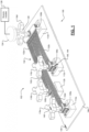
- FIG. 1 illustrates a view of a first example conductor assembly staging system according to some implementations of the present disclosure
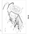
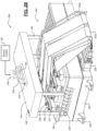
- FIGS. 2A-2B illustrate views of a second example conductor assembly staging system according to some implementations of the present disclosure.
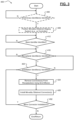
- FIG. 3 illustrates a flow diagram of a method of robotic installation of a conductor assembly according to some implementations of the present disclosure.
- the staging system 100 comprises a base member 104 having a set of receptacles 112a, 112b, 112c, 112d (collectively, "receptacles 112") attached thereto. While four receptacles are shown, it will be appreciated that other quantities of receptacles could be implemented.
- receptacles 112a, 112b, 112c, 112d have received connectors 108a, 108b, 108c, and 108d (collectively "connectors 108") and fix them therein, respectively. While differently sized square or rectangular shaped connectors are illustrated, it will be appreciated that any suitable size, shape, or type of connector could be used by providing specifically designed or universal configurations for the receptacles 112. At least temporarily attached to or defined by the connectors 108 is a respective set of robotic installation features 116a, 116b, 116c, 116d (collectively, “robotic installation features 116").
- these robotic installation features 116 are each a graspable, X-shaped member, but it will be appreciated that any suitable shaped or different type of robotic installation feature could be utilized.
- the robotic installation features 116 are temporarily interacted with by an end effector 124 (e.g., a grasping member) of the robotic installer 128. As shown, the end effector 124 has grasped robotic installation feature 116d, which gives the end effector 124 and the robotic installer 128 movable control of connector 108d via robotic installation feature 116d.
- the robotic installer 128 could include a plurality of different end effectors, such as four end effectors (i.e., one per robotic installation feature 116a, 116b, 116c, 116d). This could be necessary, for example, for the simultaneous removal of all of the connectors 108 due to unique wire cable designs, such as the one illustrated.
- four portions 132a, 132b, 132c, 132d have different widths and/or lengths and are electrically connected to the connectors 108. More specifically, portion 132a is the widest and shortest portion and is electrically connected only to connector 108d.
- Portion 132a then branches out into the three other portions 132b, 132c, 132d (from shortest to longest in length), which are in turn electrically connected to connectors 108c, 108b, and 108a, respectively.
- the conductor assembly 102 is in its entirety movably installable without potentially damaging the conductor assembly 102 (e.g., tearing a portion of the wire cable 132).
- Identification of the various components described above by the robotic installer 128 could be achieved in a variety of ways. As previously mentioned, complex high-precision viewing systems could be utilized, but these increase costs and/or complexity.
- the base member 104 defines a base identifier 136.
- identifier refers to any marking that could be identified by the robotic installer 128, including, but not limited to, barcodes, quick-read (QR) codes, numerical, alphabetical, or alphanumerical strings, or symbols/shapes.
- the base identifier could be laser etched or engraved onto the surface of the base member 104 as shown.
- receptacle 112c defines a first receptacle identifier 144 and connector 108c defines a second complimentary receptacle identifier 148.
- receptacle identifiers 144, 148 By scanning these complimentary receptacle identifiers 144, 148 as a single identifier, the robotic installer 128 could be able to verify that the connector 108c is properly fixed in the receptacle 112c. It will be appreciated that receptacle identifiers 144, 148 could also be separate and not otherwise connected or complimentary. In another implementation not covered by the invention, the receptacle identifiers 144, 148 could be predefined or known locations of the receptacles 112 with respect to the base member 104 (i.e., not a physical identifier).
- the robotic installer 128 would then know the x-y coordinate positioning of the receptacles 112.
- Installation identifiers could also be utilized, such as the installation identifier on the surface of robotic installation feature 116a. It will be appreciated, however, the robotic installation features 116 could also be identified using other suitable methods, such as predefined or known locations as described above or by recognizing the shape (e.g., an X-shape) using a scanning system.
- FIG. 2A illustrates a rear-left (RL) quarter portion 204 of the vehicle 200 where the staging system 300 is used for installation.
- the vehicle 200 defines a base or bottom surface 208 where the staging system 300 is positioned.
- the vehicle 200 comprises, among other components that are not illustrated, a driveline 212 (wheels, tires, axles, etc.) that are driven by an electric motor 216 or another suitable drive system.
- a controller 220 controls operation of at least the RL quarter portion 204 of the vehicle 200.
- the controller 220 is electrically connected to and in communication with other modules (e.g., other vehicle controllers) via cables 224a, 224b.
- the staging system 300 shows a more detailed view of the staging system 300, which includes the controller 220.
- the controller 220 is preconnected via connector 228 to a plurality of flat or band wire cables 232a and a plurality of round coaxial cables 232b. While these specific wire cable types/configurations are illustrated, it will be appreciated that the controller 220 could have any suitable preconnected wire cables.
- the controller 220 is mountable in an installation position on the base or bottom surface 208 of the vehicle 200 via brackets 236.
- the staging system 300 including the controller 220 and the other above-described components, could be initially positioned in its installation position by the robotic installer 128 as described in greater detail below.
- the staging system 300 further comprises a base member 304 that is at least temporarily attached to the top of the controller 220. Attached to the base member are a plurality of receptacles 312 having a plurality of respective connectors 308 received and fixed therein. As shown, some of the connectors 308 are connected to the flat or band wire cables 232a whereas other connectors 308 are connected to the round coaxial cables 232b. For example, these connectors 308 could be used to connect the controller 220 to respective electrical devices or systems (e.g., RADAR, LIDAR, electric traction motors, and the like).
- respective electrical devices or systems e.g., RADAR, LIDAR, electric traction motors, and the like.
- the staging system 300 further comprises preliminary robotic installation features 316, 320, 324, and 328 that are at least temporarily attached to or defined by the base member 304.
- an upper member 316 covers (e.g., and protects from damage) the connectors 308 fixed in the receptacles 312.
- the upper member 316 is at least temporarily attached to the base member 304 via corner post members 320 and respective receptacle features 324 attached to or defined by the base member 304.
- Robotic installation feature 328 e.g., a graspable handle
- the upper member 316 and then the robotic installation feature 328 could be identified by the robotic installer using respective identifiers 340, 344.
- the robotic installer 128 can position the staging system 300 (including the controller 220) in the installation position of the vehicle 200 (see FIG. 2A ).
- the preliminary robotic installation features could then be removed and installation of the connectors 308 could continue, which could involve the use of the same or a different type of end effector to interact with robotic installation features 348 of the connectors 308 (keyhole slots, equal arm cross shaped slots, t-shaped slots, etc.).
- FIG. 3 illustrates a flow diagram of a method 400 of robotic installation of a conductor assembly (a set of wire cables and a set of respective connectors) that are staged by a staging system.
- a robotic installer e.g., robotic installer 128) determines whether preliminary identifier(s) of the staging system have been identified. When true, the method 400 proceeds to optional 408. Otherwise, the method 400 ends or returns.
- the robotic installer obtains movable control of the staging system (e.g., staging system 300 with controller 220) and positions the staging system in an installation position (e.g., of vehicle 200).
- the robotic installer determines whether a base identifier for a base member of the staging system has been detected.
- the method 400 proceeds to 416. Otherwise, the method 400 returns to 412 or ends.
- the robotic installer determines whether receptacle identifier(s) of the staging system have been identified. When true, the method 400 proceeds to 420. Otherwise, the method 400 ends or returns to 416.
- the robotic installer determines whether installation features of the staging system have been identified. When true, the method 400 proceeds to 424. Otherwise, the method 400 ends or returns to 420.
- the robotic installer obtains movable control of at least some of the connectors via end effector(s) and removes the connector(s) from their respective receptacles.
- the robotic installer via the end effector(s), installs the connector(s) with corresponding electrical connectors.
- the robotic installer determines whether more connectors need to be installed (e.g., according to a set of installation instructions). When true, the method 400 returns to 420. When false, however, the method 400 end or returns to 404.
- Example embodiments are provided so that this disclosure will be thorough, and will fully convey the scope to those who are skilled in the art. Numerous specific details are set forth such as examples of specific components, devices, and methods, to provide a thorough understanding of embodiments of the present disclosure. It will be apparent to those skilled in the art that specific details need not be employed, that example embodiments may be embodied in many different forms and that neither should be construed to limit the scope of the disclosure. In some example embodiments, well-known procedures, well-known device structures, and well-known technologies are not described in detail.
- first, second, third, etc. may be used herein to describe various elements, components, regions, layers and/or sections, these elements, components, regions, layers and/or sections should not be limited by these terms. These terms may be only used to distinguish one element, component, region, layer or section from another region, layer or section. Terms such as “first,” “second,” and other numerical terms when used herein do not imply a sequence or order unless clearly indicated by the context. Thus, a first element, component, region, layer or section discussed below could be termed a second element, component, region, layer or section without departing from the teachings of the example embodiments.
- module may refer to, be part of, or include: an Application Specific Integrated Circuit (ASIC); an electronic circuit; a combinational logic circuit; a field programmable gate array (FPGA); a processor or a distributed network of processors (shared, dedicated, or grouped) and storage in networked clusters or datacenters that executes code or a process; other suitable components that provide the described functionality; or a combination of some or all of the above, such as in a system-on-chip.
- the term module may also include memory (shared, dedicated, or grouped) that stores code executed by the one or more processors.
- code may include software, firmware, byte-code and/or microcode, and may refer to programs, routines, functions, classes, and/or objects.
- shared means that some or all code from multiple modules may be executed using a single (shared) processor. In addition, some or all code from multiple modules may be stored by a single (shared) memory.
- group means that some or all code from a single module may be executed using a group of processors. In addition, some or all code from a single module may be stored using a group of memories.
- the techniques described herein may be implemented by one or more computer programs executed by one or more processors.
- the computer programs include processor-executable instructions that are stored on a non-transitory tangible computer readable medium.
- the computer programs may also include stored data.
- Non-limiting examples of the non-transitory tangible computer readable medium are nonvolatile memory, magnetic storage, and optical storage.
- the present disclosure also relates to an apparatus for performing the operations herein.
- This apparatus may be specially constructed for the required purposes, or it may comprise a general-purpose computer selectively activated or reconfigured by a computer program stored on a computer readable medium that can be accessed by the computer.
- a computer program may be stored in a tangible computer readable storage medium, such as, but is not limited to, any type of disk including floppy disks, optical disks, CD-ROMs, magnetic-optical disks, read-only memories (ROMs), random access memories (RAMs), EPROMs, EEPROMs, magnetic or optical cards, application specific integrated circuits (ASICs), or any type of media suitable for storing electronic instructions, and each coupled to a computer system bus.
- the computers referred to in the specification may include a single processor or may be architectures employing multiple processor designs for increased computing capability.
- the present disclosure is well suited to a wide variety of computer network systems over numerous topologies.
- the configuration and management of large networks comprise storage devices and computers that are communicatively coupled to dissimilar computers and storage devices over a network, such as the Internet.
Landscapes
- Engineering & Computer Science (AREA)
- Manufacturing & Machinery (AREA)
- Robotics (AREA)
- Mechanical Engineering (AREA)
- Details Of Connecting Devices For Male And Female Coupling (AREA)
- Manipulator (AREA)
Claims (15)
- Bereitstellungssystem (100; 300) für die robotergesteuerte Installation einer Leiteranordnung (102), die einen Satz von Drahtleitungen (132a, 132b, 132c, 132d; 232a) beinhaltet, der mit einem jeweiligen Satz von Steckverbindern (108a, 108b, 108c, 108d; 308) verbunden ist, wobei das Bereitstellungssystem Folgendes umfasst:ein Basiselement (104; 304), das eine Basiskennung (136) definiert, die durch einen robotergesteuerten Installierer (128) erkennbar ist;einen Satz von Aufnahmen (112a, 112b, 112c, 112d; 312), der an dem Basiselement (104) angebracht ist und jeweilige Aufnahmekennungen (144, 148) definiert, die durch den robotergesteuerten Installierer (128) erkennbar sind, wobei jede Aufnahme dazu konfiguriert ist, einen oder mehrere des Satzes von Steckverbindern (108a, 108b, 108c, 108d) der Leiteranordnung (102) aufzunehmen und temporär zu sichern; undeinen Satz von Merkmalen (116a, 116b, 116c, 116d; 348) für die robotergesteuerte Installation, der mindestens temporär an dem Satz von Steckverbindern (108a, 108b, 108c, 108d; 308) angebracht bzw. durch diesen definiert ist und jeweilige Installationskennungen definiert, die durch den robotergesteuerten Installierer (128) erkennbar sind, wobei jedes Merkmal für die robotergesteuerte Installation dazu konfiguriert ist, temporär derart mit einen Endeffektor (124; 336) des robotergesteuerten Installierers (128) zu interagieren, dass der robotergesteuerte Installierer (128) eine bewegliche Steuerung des Steckverbinders erhält, um ihn aus seiner jeweiligen Aufnahme zu entfernen und mit einem entsprechenden elektrischen Steckverbinder zu installieren,dadurch gekennzeichnet, dassmindestens eine von der Basiskennung (136), den Aufnahmekennungen (144, 148) und den Installationskennungen physikalische Kennungen in Form von auf einer jeweiligen Fläche definierten Markierungen sind.
- Bereitstellungssystem nach Anspruch 1, wobei es sich bei der Basiskennung (136) um eine auf einer Fläche des Basiselements (104) definierte abtastbare Kennung handelt.
- Bereitstellungssystem nach Anspruch 2, wobei es sich bei dem Satz von Aufnahmekennungen (144, 148) um vordefinierte Positionen in Bezug auf das Basiselement (104) handelt, die von dem robotergesteuerten Installierer (128) ohne Abtasten kennbar sind.
- Bereitstellungssystem nach Anspruch 2, wobei es sich bei dem Satz von Aufnahmekennungen (144, 148) um abtastbare Kennungen handelt, die auf Flächen der jeweiligen Aufnahmen (112a, 112b, 112c, 112d) oder auf der Fläche des Basiselements (104) in der Nähe der jeweiligen Aufnahmen definiert sind.
- Bereitstellungssystem nach Anspruch 4, wobei es sich bei den Installationskennungen um abtastbare Kennungen handelt, die auf Flächen der jeweiligen Verbinder (108a, 108b, 108c, 108d), Flächen des Satzes von den jeweiligen Verbindern entsprechenden Drahtleitungen (132a, 132b, 132c, 132d; 232a) oder Flächen der den jeweiligen Verbindern entsprechenden Merkmale (116a, 116b, 116c, 116d) für die robotergesteuerte Installation definiert sind.
- Bereitstellungssystem nach Anspruch 5, wobei entsprechende Paare von Aufnahmekennungen (144, 148) und Installationskennungen zusammen eine einzige komplementäre abtastbare Kennung bilden.
- Bereitstellungssystem nach einem der Ansprüche 1 bis 6, ferner umfassend ein oder mehrere vorläufige Merkmale (316, 320, 324, 328) für die robotergesteuerte Installation, die mindestens temporär an dem Basiselement (304) angebracht oder durch dieses definiert sind, wobei das eine oder die mehreren vorläufigen Merkmale für die robotergesteuerte Installation dazu konfiguriert sind, mit dem Endeffektor (336) oder einem anderen Endeffektor des robotergesteuerten Installierers (128) zu interagieren, um das Basiselement (304), den Satz von Aufnahmen, die Leiteranordnung und den Satz von Merkmalen (348) für die robotergesteuerte Installation in einer Installationsposition für ein Fahrzeug (200) zu positionieren.
- Bereitstellungssystem nach Anspruch 7, wobei das Basiselement (304) dazu konfiguriert ist, mindestens temporär an einer Außenfläche einer Steuerung (220) des Fahrzeugs (200) angebracht zu sein.
- Bereitstellungssystem nach Anspruch 8, wobei das eine oder die mehreren vorläufigen Merkmale (316, 320, 324, 328) für die robotergesteuerte Installation dazu konfiguriert sind, von dem Basiselement (304) entfernt zu werden, nachdem die Steuerung (220), das Basiselement (304), der Satz von Aufnahmen (312), die Leiteranordnung und der Satz von Merkmalen (324) für die robotergesteuerte Installation in der Installationsposition für das Fahrzeug (200) positioniert sind.
- Bereitstellungssystem nach Anspruch 9, wobei gegenüberliegende Enden des Satzes von Drahtleitungen (232a) der Leiteranordnung dazu konfiguriert sind, mit der Steuerung (220) vorverbunden zu werden, und wobei der Satz von Steckverbindern (308) der Leiteranordnung dazu konfiguriert ist, mit entsprechenden Sensorsystemen des Fahrzeugs (200) zugeordneten elektrischen Steckverbindern installiert zu werden.
- Verfahren (400) für die robotergesteuerte Installation einer Leiteranordnung (102), die einen Satz von Drahtleitungen (132a, 132b, 132c, 132d; 232a) und einen jeweiligen Satz von Steckverbindern (108a, 108b, 108c, 108d; 308) beinhaltet, wobei das Verfahren Folgendes umfasst:Erkennen (412) einer durch ein Basiselement (104; 304) eines Bereitstellungssystems (100; 300) definierten Basiskennung (136) durch einen robotergesteuerten Installierer (128), wobei das Bereitstellungssystem (100; 300) ferner einen Satz von an dem Basiselement (104; 304) angebrachten Aufnahmen (112a, 112b, 112c, 112d; 312) umfasst und wobei jede Aufnahme dazu konfiguriert ist, einen oder mehrere des Satzes von Steckverbindern (108a, 108b, 108c, 108d; 308) der Leiteranordnung (102) aufzunehmen und temporär zu sichern;Erkennen (416) eines Satzes von den Satz von Aufnahmen (112a, 112b, 112c, 112d; 312) definierenden Aufnahmekennungen (144, 148) durch den robotergesteuerten Installierer (128) als Reaktion auf das Erkennen der Basiskennung (136);Erkennen (420) eines Satzes von durch einen Satz von Merkmalen (116a, 116b, 116c, 116d; 348) für die robotergesteuerte Installation definierten Installationskennungen, der mindestens temporär an dem Satz von Steckverbindern (108a, 108b, 108c, 108d; 308) angebracht bzw. durch diesen definiert ist, durch den robotergesteuerten Installierer (128) als Reaktion auf das Erkennen des Satzes von Aufnahmekennungen (144, 148); undtemporäres Interagieren (424, 428) mit mindestens einem der Merkmale (116a, 116b, 116c, 116d; 348) für die robotergesteuerte Installation durch einen Endeffektor (124; 336) des robotergesteuerten Installierers (128), um eine bewegliche Steuerung eines jeweiligen Steckverbinders zu erhalten, um ihn als Reaktion auf das Erkennen des Satzes von Installationskennungen aus seiner jeweiligen Aufnahme zu entfernen und dann mit einem entsprechenden elektrischen Steckverbinder zu installieren,wobei mindestens eine von der Basiskennung (136), den Aufnahmekennungen (144, 148) und den Installationskennungen physikalische auf einer jeweiligen Fläche definierte Markierungen sind.
- Verfahren nach Anspruch 11, wobei es sich bei der Basiskennung (136) um eine auf einer Fläche des Basiselements (104) definierte abtastbare Kennung handelt, die von dem robotergesteuerten Installierer (128) abgetastet wird, um die Basiskennung (136) und das Basiselement (104) zu erkennen.
- Verfahren nach Anspruch 12, wobei es sich bei dem Satz von Aufnahmekennungen (144, 148) um vordefinierte Positionen des Satzes von Aufnahmen (112a, 112b, 112c, 112d) in Bezug auf das Basiselement (104) handelt, die der robotergesteuerte Installierer (128) ohne Abtasten kennt.
- Verfahren nach Anspruch 12, wobei es sich bei dem Satz von Aufnahmekennungen (144, 148) um abtastbare Kennungen handelt, die auf Flächen der jeweiligen Aufnahmen (112a, 112b, 112c, 112d) oder auf der Fläche des Basiselements (104) in der Nähe der jeweiligen Aufnahmen definiert sind und von dem robotergesteuerten Installierer (128) zum Erkennen des Satzes von Aufnahmekennungen und des Satzes von Aufnahmen abgetastet werden.
- Verfahren nach Anspruch 14, wobei die Installationskennungen abtastbare Kennungen sind, die auf Flächen der jeweiligen Steckverbinder (108a, 108b, 108c, 108d; 308), Flächen des Satzes von den jeweiligen Steckverbindern entsprechenden Drahtleitungen (132a, 132b, 132c, 132d; 232a) oder Flächen der den jeweiligen Steckverbindern entsprechenden Merkmale (116a, 116b, 116c, 116d; 348) für die robotergesteuerte Installation definiert sind und von dem robotergesteuerten Installierer (128) abgetastet werden, um den Satz von Installationskennungen, den Satz von Merkmalen (116a, 116b, 116c, 116d; 348) für die robotergesteuerte Installation und den Satz von Steckverbindern (108a, 108b, 108c, 108d; 308) zu erkennen.
Applications Claiming Priority (2)
| Application Number | Priority Date | Filing Date | Title |
|---|---|---|---|
| US202062956872P | 2020-01-03 | 2020-01-03 | |
| US17/120,402 US11545806B2 (en) | 2020-01-03 | 2020-12-14 | Conductor assembly staging for robotic installation |
Publications (2)
| Publication Number | Publication Date |
|---|---|
| EP3846292A1 EP3846292A1 (de) | 2021-07-07 |
| EP3846292B1 true EP3846292B1 (de) | 2025-06-04 |
Family
ID=73856954
Family Applications (1)
| Application Number | Title | Priority Date | Filing Date |
|---|---|---|---|
| EP20216774.8A Active EP3846292B1 (de) | 2020-01-03 | 2020-12-23 | Bereitstellungssystem für die robotergesteuerte installation von steckverbindern und verfahren zur robotergesteuerten installation einer leiteranordnung mit steckverbindern |
Country Status (3)
| Country | Link |
|---|---|
| US (1) | US11545806B2 (de) |
| EP (1) | EP3846292B1 (de) |
| CN (1) | CN113161844B (de) |
Families Citing this family (1)
| Publication number | Priority date | Publication date | Assignee | Title |
|---|---|---|---|---|
| US20250357708A1 (en) * | 2024-05-14 | 2025-11-20 | Aptiv Technologies AG | Connector Staging System and Method |
Family Cites Families (17)
| Publication number | Priority date | Publication date | Assignee | Title |
|---|---|---|---|---|
| DE102004033940A1 (de) * | 2004-07-14 | 2006-02-16 | Tkm Telekommunikation Und Elektronik Gmbh | Anordnung zur Identifikation und Lokalisation von mehrpoligen Steckverbindern von Datenübertragungskabeln in Mehrfachbuchsenfeldern |
| CN101142826A (zh) * | 2004-12-06 | 2008-03-12 | 北卡罗来纳科姆斯科普公司 | 使用rfid标签来检测和识别跳线互连的电信接线系统 |
| US7526582B2 (en) * | 2006-11-30 | 2009-04-28 | International Business Machines Corporation | Identifying a cable with a connection location |
| WO2009059440A1 (de) * | 2007-11-07 | 2009-05-14 | Multi-Holding Ag | Stecker und steckverbindung für roboter |
| JP2010135364A (ja) * | 2008-12-02 | 2010-06-17 | Panasonic Corp | 電子部品実装ライン及び組み立て作業機 |
| WO2011019742A1 (en) * | 2009-08-10 | 2011-02-17 | Re2, Inc. | Automated tool change assembly for robotic arm |
| JP2011206878A (ja) | 2010-03-29 | 2011-10-20 | Fuji Xerox Co Ltd | 組立検査装置及びこれを用いた組立処理装置 |
| JP5725959B2 (ja) * | 2011-04-22 | 2015-05-27 | 矢崎総業株式会社 | 圧接装置及び圧接システム |
| US9785911B2 (en) * | 2013-07-25 | 2017-10-10 | I AM Robotics, LLC | System and method for piece-picking or put-away with a mobile manipulation robot |
| US9630315B2 (en) * | 2015-08-24 | 2017-04-25 | Rethink Robotics, Inc. | Robot with hot-swapped end effectors |
| JP6865346B2 (ja) * | 2017-01-05 | 2021-04-28 | パナソニックIpマネジメント株式会社 | 電子機器組立装置および電子機器組立方法 |
| US10780575B2 (en) * | 2017-06-22 | 2020-09-22 | Phd, Inc. | Robot end effector cuff |
| US10355409B2 (en) | 2017-06-27 | 2019-07-16 | Aptiv Technologies Limited | Wiring-harness with connector staging device |
| CN109698423B (zh) * | 2017-10-23 | 2020-09-18 | 中航光电科技股份有限公司 | 线缆端部识别器及使用该对应识别器的线缆组件 |
| US10205266B1 (en) | 2017-10-30 | 2019-02-12 | Aptiv Technologies Limited | Connector wire dress cover for robotic installation |
| JP6777682B2 (ja) * | 2018-04-27 | 2020-10-28 | ファナック株式会社 | 複数の把持部を備えるロボットハンド、及びロボットハンドを用いてワイヤハーネスをハンドリングする方法 |
| KR102015796B1 (ko) * | 2019-02-01 | 2019-08-29 | (주)에바 | 전기자동차 충전용 충전 커넥터, 도킹 소켓 및 도킹 어셈블리 |
-
2020
- 2020-12-14 US US17/120,402 patent/US11545806B2/en active Active
- 2020-12-23 EP EP20216774.8A patent/EP3846292B1/de active Active
-
2021
- 2021-01-04 CN CN202110004668.3A patent/CN113161844B/zh active Active
Also Published As
| Publication number | Publication date |
|---|---|
| EP3846292A1 (de) | 2021-07-07 |
| CN113161844A (zh) | 2021-07-23 |
| CN113161844B (zh) | 2026-04-21 |
| US20210210920A1 (en) | 2021-07-08 |
| US11545806B2 (en) | 2023-01-03 |
Similar Documents
| Publication | Publication Date | Title |
|---|---|---|
| US12075586B2 (en) | Self-aligning mechanical mount and electrical connection system for electronic modules with features for robotic assembly | |
| US7648388B2 (en) | Communication relay apparatus and relay connector unit | |
| EP3846292B1 (de) | Bereitstellungssystem für die robotergesteuerte installation von steckverbindern und verfahren zur robotergesteuerten installation einer leiteranordnung mit steckverbindern | |
| CN112350114B (zh) | 将导线接触件与连接器的插入孔对准及插入的方法和系统 | |
| EP3478047B1 (de) | Montagesystem und montageverfahren | |
| CN109843513B (zh) | 评价电缆束的状态的设备和方法 | |
| CN109149222B (zh) | 具有连接器分段设备的线束 | |
| US10008786B2 (en) | Coaxial-cable-assembly, ferrule, and method of making the same | |
| EP4152528A1 (de) | Legierbare bestätigung eines verbundenen verbindungssystems | |
| WO2018080837A1 (en) | Coaxial-cable-assembly, ferrule, and method of making the same | |
| KR102029369B1 (ko) | 열수축 튜브 가열장치 | |
| US12407122B2 (en) | Direct device electrical connection to flexible circuits or other conductors | |
| EP3477797B1 (de) | Montagesystem | |
| CN111745675B (zh) | 用于自动装入电导体的设备和方法 | |
| EP4302368B1 (de) | Crimpmaschine mit anschlussvorprüfung | |
| CN110895980B (zh) | 多芯电缆的芯线排列装置及多芯电缆的芯线排列方法 | |
| CN108702839A (zh) | 通过铆接组装印刷电路板的控制方法 | |
| US11888262B2 (en) | Automotive electrical connector features for robotic installation | |
| JP7566325B2 (ja) | ケーブル端末処理装置及びケーブル端末処理方法 | |
| US11482843B2 (en) | Process of manufacturing an electrical wiring assembly and electrical wiring assembly manufactured by said process | |
| US12316081B2 (en) | Method and system for preparing a terminal for an insulated wire conductor | |
| US11437742B2 (en) | Flexible printed circuits marked with connections to vehicle circuits | |
| JP2003229225A (ja) | コネクタへの電線接続検査方法 | |
| CN117242650A (zh) | 用于机械地保护接触元件的保护装置、以及用于组装电气插接式连接器的测量方法和测量装置 | |
| CN113646139A (zh) | 用于设置在构件上的抓握元件 |
Legal Events
| Date | Code | Title | Description |
|---|---|---|---|
| PUAI | Public reference made under article 153(3) epc to a published international application that has entered the european phase |
Free format text: ORIGINAL CODE: 0009012 |
|
| STAA | Information on the status of an ep patent application or granted ep patent |
Free format text: STATUS: THE APPLICATION HAS BEEN PUBLISHED |
|
| AK | Designated contracting states |
Kind code of ref document: A1 Designated state(s): AL AT BE BG CH CY CZ DE DK EE ES FI FR GB GR HR HU IE IS IT LI LT LU LV MC MK MT NL NO PL PT RO RS SE SI SK SM TR |
|
| STAA | Information on the status of an ep patent application or granted ep patent |
Free format text: STATUS: REQUEST FOR EXAMINATION WAS MADE |
|
| 17P | Request for examination filed |
Effective date: 20220107 |
|
| RBV | Designated contracting states (corrected) |
Designated state(s): AL AT BE BG CH CY CZ DE DK EE ES FI FR GB GR HR HU IE IS IT LI LT LU LV MC MK MT NL NO PL PT RO RS SE SI SK SM TR |
|
| STAA | Information on the status of an ep patent application or granted ep patent |
Free format text: STATUS: EXAMINATION IS IN PROGRESS |
|
| 17Q | First examination report despatched |
Effective date: 20230120 |
|
| RAP3 | Party data changed (applicant data changed or rights of an application transferred) |
Owner name: APTIV TECHNOLOGIES LIMITED |
|
| RAP1 | Party data changed (applicant data changed or rights of an application transferred) |
Owner name: APTIV TECHNOLOGIES AG |
|
| RAP3 | Party data changed (applicant data changed or rights of an application transferred) |
Owner name: APTIV TECHNOLOGIES AG |
|
| GRAP | Despatch of communication of intention to grant a patent |
Free format text: ORIGINAL CODE: EPIDOSNIGR1 |
|
| STAA | Information on the status of an ep patent application or granted ep patent |
Free format text: STATUS: GRANT OF PATENT IS INTENDED |
|
| RIC1 | Information provided on ipc code assigned before grant |
Ipc: H01R 13/46 20060101ALN20250116BHEP Ipc: H01R 43/26 20060101ALN20250116BHEP Ipc: H01R 13/60 20060101AFI20250116BHEP |
|
| RIC1 | Information provided on ipc code assigned before grant |
Ipc: H01R 13/46 20060101ALN20250121BHEP Ipc: H01R 43/26 20060101ALN20250121BHEP Ipc: H01R 13/60 20060101AFI20250121BHEP |
|
| INTG | Intention to grant announced |
Effective date: 20250203 |
|
| GRAS | Grant fee paid |
Free format text: ORIGINAL CODE: EPIDOSNIGR3 |
|
| GRAA | (expected) grant |
Free format text: ORIGINAL CODE: 0009210 |
|
| STAA | Information on the status of an ep patent application or granted ep patent |
Free format text: STATUS: THE PATENT HAS BEEN GRANTED |
|
| P01 | Opt-out of the competence of the unified patent court (upc) registered |
Free format text: CASE NUMBER: APP_16409/2025 Effective date: 20250404 |
|
| AK | Designated contracting states |
Kind code of ref document: B1 Designated state(s): AL AT BE BG CH CY CZ DE DK EE ES FI FR GB GR HR HU IE IS IT LI LT LU LV MC MK MT NL NO PL PT RO RS SE SI SK SM TR |
|
| REG | Reference to a national code |
Ref country code: GB Ref legal event code: FG4D |
|
| REG | Reference to a national code |
Ref country code: CH Ref legal event code: EP |
|
| REG | Reference to a national code |
Ref country code: DE Ref legal event code: R096 Ref document number: 602020052235 Country of ref document: DE |
|
| REG | Reference to a national code |
Ref country code: IE Ref legal event code: FG4D |
|
| PG25 | Lapsed in a contracting state [announced via postgrant information from national office to epo] |
Ref country code: FI Free format text: LAPSE BECAUSE OF FAILURE TO SUBMIT A TRANSLATION OF THE DESCRIPTION OR TO PAY THE FEE WITHIN THE PRESCRIBED TIME-LIMIT Effective date: 20250604 Ref country code: ES Free format text: LAPSE BECAUSE OF FAILURE TO SUBMIT A TRANSLATION OF THE DESCRIPTION OR TO PAY THE FEE WITHIN THE PRESCRIBED TIME-LIMIT Effective date: 20250604 |
|
| REG | Reference to a national code |
Ref country code: LT Ref legal event code: MG9D |
|
| PG25 | Lapsed in a contracting state [announced via postgrant information from national office to epo] |
Ref country code: NO Free format text: LAPSE BECAUSE OF FAILURE TO SUBMIT A TRANSLATION OF THE DESCRIPTION OR TO PAY THE FEE WITHIN THE PRESCRIBED TIME-LIMIT Effective date: 20250904 Ref country code: GR Free format text: LAPSE BECAUSE OF FAILURE TO SUBMIT A TRANSLATION OF THE DESCRIPTION OR TO PAY THE FEE WITHIN THE PRESCRIBED TIME-LIMIT Effective date: 20250905 |
|
| PG25 | Lapsed in a contracting state [announced via postgrant information from national office to epo] |
Ref country code: PL Free format text: LAPSE BECAUSE OF FAILURE TO SUBMIT A TRANSLATION OF THE DESCRIPTION OR TO PAY THE FEE WITHIN THE PRESCRIBED TIME-LIMIT Effective date: 20250604 |
|
| PG25 | Lapsed in a contracting state [announced via postgrant information from national office to epo] |
Ref country code: BG Free format text: LAPSE BECAUSE OF FAILURE TO SUBMIT A TRANSLATION OF THE DESCRIPTION OR TO PAY THE FEE WITHIN THE PRESCRIBED TIME-LIMIT Effective date: 20250604 |
|
| PG25 | Lapsed in a contracting state [announced via postgrant information from national office to epo] |
Ref country code: HR Free format text: LAPSE BECAUSE OF FAILURE TO SUBMIT A TRANSLATION OF THE DESCRIPTION OR TO PAY THE FEE WITHIN THE PRESCRIBED TIME-LIMIT Effective date: 20250604 |
|
| PG25 | Lapsed in a contracting state [announced via postgrant information from national office to epo] |
Ref country code: RS Free format text: LAPSE BECAUSE OF FAILURE TO SUBMIT A TRANSLATION OF THE DESCRIPTION OR TO PAY THE FEE WITHIN THE PRESCRIBED TIME-LIMIT Effective date: 20250904 |
|
| PG25 | Lapsed in a contracting state [announced via postgrant information from national office to epo] |
Ref country code: LV Free format text: LAPSE BECAUSE OF FAILURE TO SUBMIT A TRANSLATION OF THE DESCRIPTION OR TO PAY THE FEE WITHIN THE PRESCRIBED TIME-LIMIT Effective date: 20250604 |
|
| PG25 | Lapsed in a contracting state [announced via postgrant information from national office to epo] |
Ref country code: NL Free format text: LAPSE BECAUSE OF FAILURE TO SUBMIT A TRANSLATION OF THE DESCRIPTION OR TO PAY THE FEE WITHIN THE PRESCRIBED TIME-LIMIT Effective date: 20250604 |
|
| PG25 | Lapsed in a contracting state [announced via postgrant information from national office to epo] |
Ref country code: PT Free format text: LAPSE BECAUSE OF FAILURE TO SUBMIT A TRANSLATION OF THE DESCRIPTION OR TO PAY THE FEE WITHIN THE PRESCRIBED TIME-LIMIT Effective date: 20251006 |
|
| REG | Reference to a national code |
Ref country code: AT Ref legal event code: MK05 Ref document number: 1801316 Country of ref document: AT Kind code of ref document: T Effective date: 20250604 |
|
| PG25 | Lapsed in a contracting state [announced via postgrant information from national office to epo] |
Ref country code: IS Free format text: LAPSE BECAUSE OF FAILURE TO SUBMIT A TRANSLATION OF THE DESCRIPTION OR TO PAY THE FEE WITHIN THE PRESCRIBED TIME-LIMIT Effective date: 20251004 |
|
| PGFP | Annual fee paid to national office [announced via postgrant information from national office to epo] |
Ref country code: DE Payment date: 20251117 Year of fee payment: 6 |
|
| PGFP | Annual fee paid to national office [announced via postgrant information from national office to epo] |
Ref country code: GB Payment date: 20251210 Year of fee payment: 6 |
|
| PG25 | Lapsed in a contracting state [announced via postgrant information from national office to epo] |
Ref country code: SM Free format text: LAPSE BECAUSE OF FAILURE TO SUBMIT A TRANSLATION OF THE DESCRIPTION OR TO PAY THE FEE WITHIN THE PRESCRIBED TIME-LIMIT Effective date: 20250604 Ref country code: AT Free format text: LAPSE BECAUSE OF FAILURE TO SUBMIT A TRANSLATION OF THE DESCRIPTION OR TO PAY THE FEE WITHIN THE PRESCRIBED TIME-LIMIT Effective date: 20250604 |
|
| PGFP | Annual fee paid to national office [announced via postgrant information from national office to epo] |
Ref country code: FR Payment date: 20251202 Year of fee payment: 6 |
|
| PG25 | Lapsed in a contracting state [announced via postgrant information from national office to epo] |
Ref country code: CZ Free format text: LAPSE BECAUSE OF FAILURE TO SUBMIT A TRANSLATION OF THE DESCRIPTION OR TO PAY THE FEE WITHIN THE PRESCRIBED TIME-LIMIT Effective date: 20250604 |
|
| PG25 | Lapsed in a contracting state [announced via postgrant information from national office to epo] |
Ref country code: EE Free format text: LAPSE BECAUSE OF FAILURE TO SUBMIT A TRANSLATION OF THE DESCRIPTION OR TO PAY THE FEE WITHIN THE PRESCRIBED TIME-LIMIT Effective date: 20250604 |
|
| PG25 | Lapsed in a contracting state [announced via postgrant information from national office to epo] |
Ref country code: SK Free format text: LAPSE BECAUSE OF FAILURE TO SUBMIT A TRANSLATION OF THE DESCRIPTION OR TO PAY THE FEE WITHIN THE PRESCRIBED TIME-LIMIT Effective date: 20250604 Ref country code: RO Free format text: LAPSE BECAUSE OF FAILURE TO SUBMIT A TRANSLATION OF THE DESCRIPTION OR TO PAY THE FEE WITHIN THE PRESCRIBED TIME-LIMIT Effective date: 20250604 |
|
| PG25 | Lapsed in a contracting state [announced via postgrant information from national office to epo] |
Ref country code: IT Free format text: LAPSE BECAUSE OF FAILURE TO SUBMIT A TRANSLATION OF THE DESCRIPTION OR TO PAY THE FEE WITHIN THE PRESCRIBED TIME-LIMIT Effective date: 20250604 |
|
| REG | Reference to a national code |
Ref country code: DE Ref legal event code: R097 Ref document number: 602020052235 Country of ref document: DE |
|
| PLBE | No opposition filed within time limit |
Free format text: ORIGINAL CODE: 0009261 |
|
| STAA | Information on the status of an ep patent application or granted ep patent |
Free format text: STATUS: NO OPPOSITION FILED WITHIN TIME LIMIT |
|
| PG25 | Lapsed in a contracting state [announced via postgrant information from national office to epo] |
Ref country code: DK Free format text: LAPSE BECAUSE OF FAILURE TO SUBMIT A TRANSLATION OF THE DESCRIPTION OR TO PAY THE FEE WITHIN THE PRESCRIBED TIME-LIMIT Effective date: 20250604 |
|
| REG | Reference to a national code |
Ref country code: CH Ref legal event code: L10 Free format text: ST27 STATUS EVENT CODE: U-0-0-L10-L00 (AS PROVIDED BY THE NATIONAL OFFICE) Effective date: 20260416 |