EP3846152A1 - Medium and winding method - Google Patents
Medium and winding method Download PDFInfo
- Publication number
- EP3846152A1 EP3846152A1 EP19864811.5A EP19864811A EP3846152A1 EP 3846152 A1 EP3846152 A1 EP 3846152A1 EP 19864811 A EP19864811 A EP 19864811A EP 3846152 A1 EP3846152 A1 EP 3846152A1
- Authority
- EP
- European Patent Office
- Prior art keywords
- slit
- layer
- print label
- edge
- release material
- Prior art date
- Legal status (The legal status is an assumption and is not a legal conclusion. Google has not performed a legal analysis and makes no representation as to the accuracy of the status listed.)
- Pending
Links
Images




Classifications
-
- G—PHYSICS
- G09—EDUCATION; CRYPTOGRAPHY; DISPLAY; ADVERTISING; SEALS
- G09F—DISPLAYING; ADVERTISING; SIGNS; LABELS OR NAME-PLATES; SEALS
- G09F3/00—Labels, tag tickets, or similar identification or indication means; Seals; Postage or like stamps
- G09F3/08—Fastening or securing by means not forming part of the material of the label itself
- G09F3/10—Fastening or securing by means not forming part of the material of the label itself by an adhesive layer
-
- G—PHYSICS
- G09—EDUCATION; CRYPTOGRAPHY; DISPLAY; ADVERTISING; SEALS
- G09F—DISPLAYING; ADVERTISING; SIGNS; LABELS OR NAME-PLATES; SEALS
- G09F3/00—Labels, tag tickets, or similar identification or indication means; Seals; Postage or like stamps
- G09F3/02—Forms or constructions
- G09F3/0295—Labels or tickets for tubes, pipes and the like
-
- G—PHYSICS
- G09—EDUCATION; CRYPTOGRAPHY; DISPLAY; ADVERTISING; SEALS
- G09F—DISPLAYING; ADVERTISING; SIGNS; LABELS OR NAME-PLATES; SEALS
- G09F3/00—Labels, tag tickets, or similar identification or indication means; Seals; Postage or like stamps
- G09F3/08—Fastening or securing by means not forming part of the material of the label itself
- G09F3/18—Casings, frames or enclosures for labels
- G09F3/20—Casings, frames or enclosures for labels for adjustable, removable, or interchangeable labels
- G09F3/205—Casings, frames or enclosures for labels for adjustable, removable, or interchangeable labels specially adapted for electric cables, pipes or the like
-
- G—PHYSICS
- G09—EDUCATION; CRYPTOGRAPHY; DISPLAY; ADVERTISING; SEALS
- G09F—DISPLAYING; ADVERTISING; SIGNS; LABELS OR NAME-PLATES; SEALS
- G09F3/00—Labels, tag tickets, or similar identification or indication means; Seals; Postage or like stamps
- G09F3/02—Forms or constructions
- G09F2003/0201—Label sheets intended to be introduced in a printer, e.g. laser printer
-
- G—PHYSICS
- G09—EDUCATION; CRYPTOGRAPHY; DISPLAY; ADVERTISING; SEALS
- G09F—DISPLAYING; ADVERTISING; SIGNS; LABELS OR NAME-PLATES; SEALS
- G09F3/00—Labels, tag tickets, or similar identification or indication means; Seals; Postage or like stamps
- G09F3/02—Forms or constructions
- G09F2003/0202—Forms or constructions printed before use
-
- G—PHYSICS
- G09—EDUCATION; CRYPTOGRAPHY; DISPLAY; ADVERTISING; SEALS
- G09F—DISPLAYING; ADVERTISING; SIGNS; LABELS OR NAME-PLATES; SEALS
- G09F3/00—Labels, tag tickets, or similar identification or indication means; Seals; Postage or like stamps
- G09F3/02—Forms or constructions
- G09F2003/023—Adhesive
-
- H—ELECTRICITY
- H02—GENERATION; CONVERSION OR DISTRIBUTION OF ELECTRIC POWER
- H02G—INSTALLATION OF ELECTRIC CABLES OR LINES, OR OF COMBINED OPTICAL AND ELECTRIC CABLES OR LINES
- H02G1/00—Methods or apparatus specially adapted for installing, maintaining, repairing or dismantling electric cables or lines
- H02G1/06—Methods or apparatus specially adapted for installing, maintaining, repairing or dismantling electric cables or lines for laying cables, e.g. laying apparatus on vehicle
Definitions
- the present invention relates to a medium that is mounted and used in a printer, and a method of wrapping the same.
- a label (corresponding to the medium) known in the art is provided with adhesive on the back side thereof.
- the label is mounted in a printer. Once printed, the label is used by attaching the label to the curved surface of an object.
- the user may wish to wrap the label around an object such that the label is rotatably attached.
- a technology for coating the adhesive on the label with varnish or another non-adhesive material so that adhesive in the portion of the label present around the outside of the object does not adhere to the object see Patent Literature PTL 1, for example).
- a configuration such as the conventional technology described above, in which the adhesive is coated with a non-adhesive material such as varnish, may degrade due to stress incurred when wrapping the label around the object, changes in ambient conditions, or aging. With such degradation, the adhesive may become exposed and inhibit rotation of the label.
- the present invention provides a medium to be mounted in and to be printed with a printer.
- the medium includes: a release material; a slit; and a print label.
- the release material is opaque.
- the slit is provided in the release material and has a square shape including a first side, a second side, a third side, and a fourth side. The first side and the second side oppose each other. The third side and the fourth side oppose each other.
- the print label is fixed to the release material so as to span across the first side of the slit.
- the medium according to the present invention has a layered structure in which a print label is fixed to an opaque release material, and is attached to the outer circumference of an object such as a cable and the like. That is, when attaching the medium to an object, the release material is peeled off, and subsequently the medium is bent into a concave shape so that the adhesive exposed after peeling the release material therefrom is on the inside. Next, the medium is wrapped once around the cable and the like placed on the inside of the concave-shaped medium to form a cylindrical body encircling the cable and the like. Subsequently, the distal end portion of the medium is bonded to the base end portion of the medium by adhesion of the adhesive. As a result, the medium can be attached to the cable and the like by wrapping the medium once around the cable and the like, while fixing the shape of the medium itself by adhesion described above.
- the user may wish to wrap the medium around the cable and the like such that the medium is rotatably attached.
- the adhesive placed on the inside of the cylindrical body i.e., the portion located on the outer circumference of the cable
- the release material when the release material is peeled off, a portion of the release material is left on the print label to prevent the adhesive from adhering to the cable and the like.
- a slit having a square shape including a first side and a second side opposing each other is provided in a release material layer, and a print label is provided so as to span across the first side at least. Accordingly, when the release material is peeled off, a square region of the release material located inside the slit can be separated from the remaining portion of the release material and can be left on the print label (that is, to cover the adhesive).
- this structure does not degrade due to stress incurred while being wrapped around the object, changes in ambient conditions, or aging, as occurs in the conventional method of coating the adhesive with varnish or other non-adhesive material.
- the adhesive does not become exposed and does not impede rotation.
- rotation of the medium relative to an object does not become impeded due to stress incurred when wrapped around an object, changes in ambient conditions, or aging.
- a label-creating device 1 (corresponding to the printer) has a control circuit 2, an operation unit 3 on which the user (operator) can perform desired operations, a display unit 4 for displaying prescribed information, a RAM 5 for storing various information, a conveying roller 6, a print head 7, a cutting lever 8, and a cutter 9.
- a cartridge holder 12 is also provided in the label-creating device 1.
- a tape cartridge 10 (corresponding to the cassette) is detachably mounted in the cartridge holder 12.
- the tape cartridge 10 has a casing 11, and a tape roll 10A (depicted in the drawing as concentric circles for simplification but actually wound into a roll) accommodated in the casing 11.
- a printing tape To is wound in a roll shape to form the tape roll 10A.
- the tape cartridge 10 may be a die-cut label type or a continuous length type (described later with reference to Fig. 11 ).
- a printing tape To having half-cuts HC (described later with reference to Fig. 2 ) formed therein is wound about the tape roll A.
- a printing tape To having no half-cuts HC is wound about the tape roll A.
- Either type of tape cartridge 10 can be used in the label-creating device 1.
- the half-cuts HC are configured of perforations, for example.
- a "perforation" denotes a plurality of holes provided intermittently in a fine line along the surface direction of a target layer, with each hole penetrating the target layer in the thickness direction (the same applies hereafter).
- the control circuit 2 is provided with a CPU and a ROM not shown in the drawings.
- the control circuit 2 executes various programs pre-stored in the ROM while utilizing the temporary storage function of the RAM 5 in order to perform overall control of the label-creating device 1.
- the conveying roller 6 is disposed in opposition to the print head 7.
- the printing tape To paid out from the tape roll 10A is interposed between the conveying roller 6 and print head 7. By rotating, the conveying roller 6 conveys the printing tape To while pulling the printing tape To from the tape roll 10A.
- the print head 7 prints desired print objects (see the printed images R described later) on main label parts Lo (described later in greater detail) of the printing tape To conveyed by the conveying roller 6.
- the print objects are user-specified characters, icons, and the like.
- the cutter 9 When actuated through a user operation on the cutting lever 8, the cutter 9 cuts off a printed section of a printing tape T (described later in greater detail) having a plurality of print labels L formed along the conveying direction. Note that the printing tapes To and T correspond to the medium in the claims.
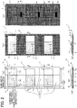
- Figs. 2(a) through 2(e) show the detailed structure of the printing tape To.
- Fig. 2(a) is a plan view showing the printing tape To in an unprinted state. The up-down direction in the drawing corresponds to the conveying direction (the tape length direction), the left-right direction in the drawing corresponds to the tape width direction, and the near-far direction in the drawing corresponds to the tape thickness direction.
- Fig. 2(b) shows a plan view of the printing tape T on which the printed image R has been printed and after an excess label portion has been peeled off.
- Fig. 2(c) is a rear view of the printed printing tape T.
- Fig. 2(d) is a cross-sectional view taken along the section IIx-IIx of the structure shown in Fig. 2(a).
- Fig. 2(e) is a cross-sectional view taken along the section IIy-IIy of the structure shown in Fig. 2(b) .
- the printing tape To includes an opaque release material layer 24, a transparent adhesive layer 22 (corresponding to an adhesive layer), and a transparent base layer 21 having compositions that include paper or colored film or fabric or metal.
- the release material layer 24, adhesive layer 22, and base layer 21 are layered in sequence in the thickness direction (the depth direction in the perspective of Fig. 2(a) and Fig. 2(b) , the vertical direction in Fig. 2(d) , and hence the direction in which each layer is laminated, as will be described later) from a first side of the thickness direction (the bottom in Fig. 2(d) , the far side in Figs. 2(a) and 2(b) , and the near side in Fig.
- the adhesive layer 22 may be provided in part, rather than over the entire surface, on the back side (the bottom side in Fig. 2(d) ) of the base layer 21, i.e., between the base layer 21 and release material layer 24.
- main label parts Lo (or print labels L having a printed image R formed on each of the main label parts Lo) are arranged successively in the tape length direction (the up-down direction in the drawings) while separated by an excess label portion LB (see Fig. 2(a) ).
- main label parts Lo (or print labels L) are arranged discretely along the tape length direction.
- These main label parts Lo (or print labels L) are all arranged with their longitudinal directions oriented in the tape width direction (left-right direction in the drawings).
- the base layer 21 is divided by the half-cuts HC (perforations) into the main label parts Lo and the remaining excess label portion LB and is fixed via the adhesive layer 22 to the surface on the second side of the release material layer 24 in the thickness direction.
- the main label parts Lo correspond to the print label in the claims
- the excess label portion LB corresponds to the label in the claims.
- a print background layer 25 (corresponding to a printing portion) is also partially provided on the front-side (the top in Fig. 2(d) ) surface of the base layer 21 at a position within the main label part Lo (see Figs. 2(a), 2(b), 2(d), and 2(e) ).
- the print background layer 25 has a suitable non-transparent color and the thermal head 7 forms the printed image R therein.
- each main label part Lo has a length Wb2 in the tape width direction and a width Wb1 in the tape length direction and includes three areas: an adhesive area D1 constituting the left end portion in the drawings; a non-adhesive area D23 provided adjacent to the adhesive area D1 and corresponding to the print background layer 25; and an adhesive area D4 provided adjacent to the non-adhesive area D23.
- a length Ws2 of the printing tapes To and T in the tape width direction is greater than the length Wb2 of the main label parts Lo in the tape width direction.
- rectangular (square) slits S are formed in the release material layer 24.
- Each of these slits S is arranged such that the adhesive area D1 and adhesive area D4 are positioned in a slit outer area SO outside the slit S in a plan view, while the non-adhesive area D23 is positioned in a slit inner area SI inside the slit S in a plan view.
- the print background layer 25 is arranged with at least a portion overlapping at least a portion of the slit inner area SI enclosed by the slit S.
- the print background layers 25 have the same dimensions in the tape width direction and tape length direction as the slits S and the entirety of the print background layers 25 overlap areas AR within the corresponding slits S.
- the slits S overlap the print background layers 25 in a plan view.
- marks PM are provided on the release material layer 24 in intermediate parts between neighboring slits S.
- the marks PM are used for positioning control when the conveying roller 6 conveys the printing tape To. That is, the label-creating device 1 is provided with a well-known reflective optical sensor (not illustrated) having a light-emitting unit and a light-receiving unit. During the positioning control, the optical sensor emits light from the light-emitting unit while the light-receiving unit receives light reflected off the release material layer 24. At this time, the marks PM on the release material layer 24 are detected based on the difference in the amount of light received between portions of the release material layer 24 on which the marks PM are provided and all other portions, and the printing tape To is positioned based on these detections.
- the rectangular slits S are juxtaposed on the printing tapes To and T along the up-down direction, and a print background layer 25 is positioned in each slit inner area AR surrounded by a slit S.
- a printed image R is formed in the print background layer 25 in each of the print labels L.
- the printed images R are print objects respectively configured of the text "A01,” “A02,” “A03,” and the like in this example.
- the term "slit” in this specification denotes a cut penetrating the target layer in the thickness direction (the same applies hereafter). A configuration in which the target layer is partially cut in the thickness direction (the cut enters a fixed amount in the thickness direction) may be used in place of these slits (the same applies hereafter).
- a printing tape To may be provided with an initial configuration that omits the excess label portion LB from Fig. 2(a) (i.e., a configuration that omits printed images R from Fig. 2(b) ).
- each print label L included on the printing tape T and having a printed image R formed on the print background layer 25 as described above can be peeled off while leaving the square-shaped portion of the release material layer 24 located inside the slit S (the portion included in the slit inner area AR) on the adhesive layer 22 side (i.e., with the square-shaped portion covering the adhesive layer 22), as shown in Fig. 3(b) .
- this peeled off portion will simply be called the "print label L" for convenience.
- a space (a window WD) will remain in the strip-like release material layer 24 inside the rectangular slit S, as illustrated in Fig. 3(b) .
- each slit S has a square shape. More specifically, as shown in Fig. 3(b) , the slit S includes opposing sides configured of a side Sa (corresponding to the first side) and a side Sb (corresponding to the second side), and opposing sides configured of a side Sc (corresponding to the third side) and a side Sd (corresponding to the fourth side).
- the main label part Lo i.e., the print label L after being printed; the same applies hereafter
- the print background layer 25 is formed in a square shape having a side 25a (corresponding to the ninth side, and corresponding to the side Sa of the slit S), a side 25b (corresponding to the tenth side, and corresponding to the side Sb of the slit S), a side 25c (corresponding to the eleventh side, and corresponding to the side Sc of the slit S), and a side 25d of the slit S (corresponding to the twelfth side, and corresponding to the side Sd of the slit S).
- the main label part Lo is formed in a square shape with opposing sides configured of a side La (corresponding to the fifth side) and a side Lb (corresponding to the sixth side), and opposing sides configured of a side Lc (corresponding to the seventh side) and a side Ld (corresponding to the eighth side).
- the side Lc and side Ld are parallel to the side Sc and side Sd of the slit S and within proximity (a distance within 3 mm, for example) of the same respectively.
- the excess label portion LB is connected to the sides Lc and Ld and sides La and Lb of each main label part Lo via half-cuts HC configured of perforations.
- the perforated half-cuts HC may be replaced with slits similar to the slits S described above.
- the printing tape To must be provided with the excess label portion LB to prevent the main label parts Lo or print labels L from flapping or peeling off the printing tape To while being conveyed through the label-creating device 1 in the tape length direction.
- the print background layer 25 may be smaller than the slit inner area AR enclosed by the slit S. More specifically, the side Sc of the slit S may be offset toward the side Ld of the main label part Lo rather than the side Lc of the main label part Lo, and side Sd of the slit S may be offset toward the side Lc of the main label part Lo rather than the side Ld of the main label part Lo.
- the side La of the main label part Lo is on the side closer to the side Sa than the side Sb of the slit S
- the side Lb of the main label part Lo is on the side closer to the side Sb than the side Sa of the slit S, as illustrated in Fig. 3(b) .
- the shortest distance b' between the side Sa of the slit S and the side La of the main label part Lo is greater than the shortest distance c' between the side Sb of the slit S and the side Lb of the main label part Lo. Further, the shortest distance a' between the side Sa and side Sb of the slit S is between one and three times the shortest distance b'.
- the side La of the main label part Lo is on the side closer to the side 25a than the side 25b of the print background layer 25, and the side Lb of the main label part Lo is on the side closer to the side 25b than the side 25a of the print background layer 25, as illustrated in Fig. 3(b) .
- the shortest distance b between the side 25a of the print background layer 25 and the side La of the main label part Lo is greater than the shortest distance c between the side 25b of the print background layer 25 and the side Lb of the main label part Lo.
- the shortest distance a between the side 25a and side 25b of the print background layer 25 is between one and three times the shortest distance b.
- the shortest distance b between the side 25a of the print background layer 25 and the side La of the main label part Lo is greater than the shortest distance c between the side 25b of the print background layer 25 and the side Lb of the main label part Lo. Further, the shortest distance a between the side 25a and side 25b of the print background layer 25 is between one and three times the shortest distance b.
- Fig. 4(a) shows a plan view of one print label L separated as described above
- Fig. 4(b) shows a cross-sectional view along the section IVB-IVB in Fig. 4(a) .
- the print label L shown in Figs. 4(a) and 4(b) has the transparent base layer 21, the transparent adhesive layer 22, and the opaque release material layer 24 arranged in sequence along the thickness direction (the depth direction in Fig. 4(a) and the left-right direction in Fig. 4(b) ) from the left side to the right side in Fig. 4(b) .
- the print background layer 25 having the printed image R is partially provided on the second side surface of the base layer 21 relative to the thickness direction.
- the print label L is provided with the adhesive area D1, non-adhesive area D23, and adhesive area D4 described above from another side (the top in the drawing) of the tape length direction (corresponding to the first direction) toward one side (the bottom in the drawing) in the tape length direction.
- the base layer 21 and adhesive layer 22 are layered in order from the second side toward the first side of the thickness direction (from the left side to the right side in Fig. 4(b) ).
- the entire region of the adhesive area D1 is provided with an adhesive property owing to the adhesive layer 22.
- the adhesive area D1 is provided with a length L1 in the tape width direction.
- the print background layer 25 provided with the printed image R, the base layer 21, the adhesive layer 22, and the release material layer 24 are layered in order from the second side toward the first side of the thickness direction (from the left side to the right side in Fig. 4(b) ).
- the entire area of the non-adhesive area D23 is non-adhesive, as the adhesive property of the adhesive layer 22 is inhibited by the release material layer 24.
- the print background layer 25 is formed by applying ink (an ink coating layer) of a suitable color (a light transmissive color in this example, including transparent colors) on the base layer 21, and the thermal head 7 forms the printed image R, which is the text "A01," as described above.
- the non-adhesive area D23 has a length L3 in the tape width direction.
- the base layer 21 and adhesive layer 22 are layered in order from the second side toward the first side of the thickness direction (from the left side to the right side in Fig. 4(b) ).
- the entire area of the adhesive area D4 is provided with an adhesive property through the adhesive layer 22.
- the adhesive area D4 has a length L4 in the tape width direction.
- the entire surface of the print label L on the second side of the thickness direction corresponds to the front surface in the claims, and the entire surface of the print label L on the first side of the thickness direction corresponds to the back surface of the claims.
- Fig. 5 shows a sample procedure for attaching the print label L to an object.
- the print label L is attached by wrapping the print label L around a cable-like (i.e., columnar-shaped) object 302 (hereinafter simply called a "cable 302" for convenience) having a diameter 2r.
- a cable-like object 302 hereinafter simply called a "cable 302" for convenience
- the print label L extends in the order: adhesive area D1 -> non-adhesive area D23 covered by the separated release material layer 24 -> adhesive area D4. (In other words, the adhesive layer 22 of the print label L is exposed in the adhesive areas D1 and D4, which are not covered by the release material layer 24.)
- the adhesive area D1 and non-adhesive area D23 of the print label L are bent into a concave shape (not illustrated) so that the release material layer 24 side (the right side in Fig. 5(a) ) is on the inside.
- the cable 302 is placed on the inside of the concave-shaped print label L, and the print label L is wrapped once around the cable 302 to form a cylindrical body encircling the cable 302, as shown in Fig. 5(b) .
- the adhesive layer 22 (functioning as the second portion of the adhesive layer on the side of the second side in the claims) on the adhesive area D 1 positioned on the distal end and the adhesive layer 22 (functioning as the first portion of the adhesive layer on the side of the first side in the claims) on the adhesive area D4 are bonded together while aligning the positions of the two adhesive layers 22 in the tape width direction (also known as butt-sealing).
- the length of the release material layer 24 in the tape width direction is at least greater than or equal to the circumference 2 ⁇ r of the cable 302.
- the print label L can be attached to the cable 302 so as to be rotatable about the same by wrapping the non-adhesive area D23 of the print label L around the cable 302 so that the print label L is in a non-adhering state, while fixing the shape of the print label L itself by bonding the two adhesive layers 22 together.
- the adhesive layer 22 of the print label L can be prevented from becoming fixed to the cable 302.
- the remaining portion of the adhesive area D4 that was not used in the structure encircling the cable 302 is wrapped in the direction of the arrow G indicated in Fig. 5(b) so that the bonded portion of the adhesive area D1 and adhesive area D4 are on the inside (for example, the adhesive area D1 contacts a back-fold region Y, as indicated by an arrow Z).
- the adhesive area D4 is wrapped around the outer circumferential portion of the non-adhesive area D23 while covering the non-adhesive area D23 that constitutes the cylindrical body (see Fig. 5(c) ).
- the adhesive property of the adhesive layer 22 to affix the adhesive area D4 to the outer circumferential portion of the non-adhesive area D23, the operation for attaching the print label L to the cable 302 is complete.
- Fig. 6 shows a sample application of the print label L described above.
- a cable for use with a switching hub that relays information over a network such as a wired LAN, is applied as the cable 302.
- the switching hub 300 in Fig. 6 has eight slots 301 in each of a top row and a bottom row (a total of sixteen slots).
- plates PL indicating the ID names "A01” through “A08” are provided in sequence from the left to correspond to the eight slots 301 in the top row, and plates PL indicating the ID names "A09” through “A16” are provided in sequence from the left to correspond to the eight slots 301 in the bottom row.
- the cable 302 must be appropriately connected to the corresponding slot 301.
- the print label L described above is mounted on the end of each cable 302 that is to be inserted into one of the connector slots 301, and the printed image R formed on each print label L has the same content as the ID name for the slot 301 to which the cable 302 is to be connected.
- a print label L printed with the same text as the ID name on the plate PL of the slot 301 to which the cable 302 is to be connected is affixed to the cable 302. This clarifies the correlations between slots 301 and cables 302 that are to be connected to the slots 301, thereby preventing incorrect wiring.
- Fig. 7 schematically shows the attached state of the print label L on the cable 302.
- An axial center k of the cable 302 is also indicated in the drawing.
- the print label L is affixed to the cable 302 constituting the object so as to be rotatable about the cable 302.
- the print background layer 25 is arranged such that the printed image R of "A01" provided on the print background layer 25 is facing the viewer of the drawing.
- the transparent adhesive area D4 is actually present so as to cover the outer circumferential side of the non-adhesive area D23, as depicted in Fig. 5(c) , the adhesive area D4 has been omitted from Fig.
- the print label L can be shifted to the orientation shown in Fig. 7(b) by rotating the print label L in the direction of the dashed arrow (i.e., a circumferential direction) from the state shown in Fig. 7(a) .
- the print label L is rotatable as described above owing to the release material layer 24. Accordingly, by rotating the print label L in the direction opposite that described above to the position shown in Fig. 7(a) , the printed image R can be made visible.
- the release material layer 24 when the release material layer 24 is peeled off the main label part Lo as described with reference to Fig. 3(b) , a square-shaped area of the release material layer 24 positioned inside the slit S separates from the remaining portion of the release material layer 24.
- this square-shaped area of the release material layer 24 remains on the main label part Lo (the print label L) and covers the adhesive layer 22.
- the adhesive layer 22 in the cylindrical body can be prevented from adhering to the cable 302.
- the print label L can eb rotatably attached to the cable 30.
- this structure does not degrade due to stress incurred while being wrapped around the object, changes in ambient conditions, or aging, as occurs in the conventional method of coating the adhesive layer 24 with varnish or other non-adhesive material.
- the adhesive layer 24 does not become exposed and does not impede rotation.
- the release material layer 24 were transparent and all other portions of the print label L were also transparent, the contents of the printed image R formed by the label-creating device 1 could be difficult to see depending on the color of the cable 302.
- the print label L in the present embodiment can suppress such adverse effects by using an opaque release material layer 24 having a composition that includes paper or colored film or fabric or metal.
- a particular feature of the present embodiment is that the excess label portion LB is connected to the sides Lc and Ld of the main label part Lo (the print label L) through the perforated half-cuts HC.
- This configuration can suppress the main label part Lo (the print label L) from peeling off the release material layer 24 while being conveyed through the label-creating device 1 better than if the main label part Lo (the print label L) were fixed to the release material layer 24 without the excess label portion LB.
- a nontransparent release material layer 24 can be achieved by configuring the release material layer 24 of a composition that includes paper or colored film or fabric or metal.
- the main label parts Lo (or the print labels L having printed images R formed on the corresponding main label parts Lo) are arranged in series on the printing tapes To and T while separated from each other by the excess label portion LB (see Fig. 2(a) ). Further, the base layer 21 is separated between the main label parts Lo and the excess label portion LB by the half-cuts HC and is fixed to the second side surface of the release material layer 24 in the thickness direction via the adhesive layer 22.
- the main label parts Lo or print labels L are arranged such that their longitudinal directions are aligned with the tape length direction of the printing tapes To and T. That is, a plurality of the slits S are provided in the release material layer 24 along the tape length direction, and a plurality of main label parts Lo or print labels L are fixed to the release material layer 24 along the tape length direction.
- the release material layer 24 is elongated in the tape length direction, which is parallel to the side Sc of each of the plurality of slits S. A plurality of sets that each comprise one slit S and one corresponding main label part Lo (print label L) is juxtaposed along this length direction.
- Each main label part Lo has a length Wb in the tape width direction and three areas: the adhesive area D1, non-adhesive area D23, and adhesive area D4.
- the printing tapes To and T have a length Ws in the tape width direction that is greater than the length Wb of the main label part Lo in the tape width direction.
- rectangular-shaped (square-shaped) slits S are provided in the release material layer 24, and the print background layers 25 are arranged so that at least a portion of each print background layer 25 overlaps at least a portion of the slit inner area AR enclosed by the corresponding slit S.
- the slits S overlap the print background layers 25 in a plan view.
- marks PM are provided on the release material layer 24 for positioning control when the printing tape To is conveyed.
- Each mark PM is provided in an intermediate part between two neighboring slits S, S (but in a plan view are positioned inside the main label part Lo or print label L, as illustrated in Fig. 8(c) and Fig. 8(d) ).
- printed images R configured of the text "A01,” “A02,” and "A03" are formed on the print background layers 25 of the corresponding print labels L.
- a printing tape To may be provided with an initial configuration that omits the excess label portion LB from Fig. 8(a) (i.e., a configuration that omits the printed images R from Fig. 8(b) ).
- each print label L having a printed image R formed on the print background layer 25 can be peeled off while the square-shaped portion of the release material layer 24 positioned inside the slit S remains covering the release material layer 24, as illustrated in Fig. 9(d) .
- a space (a window WD) will remain on the strip-like release material layer 24 inside the rectangular slit S, as illustrated in Fig. 9(f) .
- each slit S has opposing sides configured of a side Sa (corresponding to the first side) and a side Sb (corresponding to the second side) and opposing sides configured of a side Sc (corresponding to the third side) and a side Sd (corresponding to the fourth side), as illustrated in Figs. 9(d) through 9(f) .
- the main label part Lo (print label L) is fixed to the release material layer 24 so as to span across both the side Sa and the side Sb of the corresponding slit S (see Figs. 9(d) through 9(f) ).
- the print background layer 25 is formed in a square shape having the side 25a (corresponding to the ninth side), the side 25b (corresponding to the tenth side), the side 25c (corresponding to the eleventh side), and the side 25d (corresponding to the twelfth side).
- the main label part Lo is formed in a square shape having opposing sides configured of a side La (corresponding to the fifth side) and a side Lb (corresponding to the sixth side) and opposing sides configured of a side Lc (corresponding to the seventh side) and a side Ld (corresponding to the eighth side).
- the excess label portion LB described above is connected to the sides Lc and Ld and the sides La and Lb of the main label part Lo through the perforated half-cuts HC.
- slits similar to the slits S described above may be provided in place of the perforated half-cuts HC only between the excess label portion LB and the sides La and Lb of the main label part Lo.
- the printing tape To must be provided with the excess label portion LB described above.
- the print background layer 25 may be smaller than the slit inner area AR enclosed in the corresponding slit S.
- the present variation can obtain the same effects described in the present embodiment.
- a plurality of sets each comprising one slit S and one corresponding main label part Lo (print label L), is provided on the release material layer 24.
- the sets are arranged discretely on the release material layer 24 at intervals in the tape length direction (with the excess label portion LB present between sets), but variation (1) is not limited to this configuration. That is, sets of slits S and main label parts Lo (print labels L) may be arranged adjacent to each other (with no gaps therebetween) on the release material layer 24. This structure can also obtain the same effects described above.
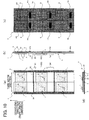
- the length of the release material layer 24 may be widened in the tape width direction, and a plurality of columns (two columns in this example) of main label parts Lo (print labels L) may be arranged on the release material layer 24 adj acent to each other in the tape width direction.
- a plurality of label bodies may be arranged along the tape length direction.
- Each label body has a plurality of sets (two sets in this example), each comprising a slit S and a main label part Lo (print label L), arranged adjacent to each other in the tape width direction. This variation can also obtain the same effects described above.
- a printing tape To without the half-cuts HC described above (known as a continuous length type) is wound into the tape roll A and accommodated in the tape cartridge 10.
- Figs. 11(a) through 11(d) show a detailed structure of the printing tapes To and T in this variation.
- Fig. 11(a) is a plan view of an unprinted printing tape To;
- Fig. 11(b) is a plan view of the printing tape T after the printed image R has been printed;
- Fig. 11(c) is a rear view of the printed printing tape T;
- Fig. 11(d) is a cross-sectional view taken along the section XIx-XIx in the structure shown in Fig. 11(a);
- Fig. 11(e) is a cross-sectional view taken along the section XIy-XIy in the structure shown in Fig. 11(b) .
- the printing tapes To and T include an opaque release material layer 24, a transparent adhesive layer 22 (corresponding to the adhesive layer), and a transparent base layer 21 having compositions that include paper or colored film or fabric or metal, as shown in Figs. 11(a) through 11(e) .
- the release material layer 24, adhesive layer 22, and base layer 21 are layered in sequence from a first side of the thickness direction (the bottom in Fig. 11(d) and Fig. 11(e) , the far side in Fig. 11(a) and Fig. 11(b) , and the near side in Fig. 11(c) ) toward a second side of the thickness direction (the top in Fig. 11(d) and Fig. 11(e) , the near side in Fig. 11(a) and Fig. 11(b) , and the far side in Fig. 11(c) ).
- the base layer 21 is fixed to the surface of the release material layer 24 on the second side in the thickness direction via the adhesive layer 22.
- the adhesive layer 22 may be provided in part, rather than over the entire surface, on the back side of the base layer 21, i.e., between the base layer 21 and release material layer 24.
- a print background layer 25 (corresponding to the printing layer) is also partially provided on the front-side (the top in Fig. 11(d) and Fig. 11(e) ) surface of the base layer 21.
- the print background layer 25 has a suitable nontransparent color and the printed image R formed by the thermal head 7.
- the print background layer 25 is a rectangular-shaped layer having an edge 25A (corresponding to the first edge) on one side (the right side in Fig. 11(b) ), and an edge 25B (corresponding to the second edge) on the other side (the left side in Fig. 11(b) ).
- the length of the printing tapes To and T in the tape width direction is the Wb2 described above.
- a plurality of slits is provided in the release material layer 24.
- the slits extend linearly in the tape length direction (corresponding to the first direction) from one short side of the rectangular release material layer 24 (the bottom in Fig. 11(c) ) to the other short side (the top in Fig. 11(c) ).
- the release material layer 24 is provided with two slits, and specifically a slit S1 (corresponding to the first slit), and a slit S2 (corresponding to the second slit).
- the base layer 21 is fixed to the release material layer 24 via the adhesive layer 22 so as to span across both the slit S1 and the slit S2.
- the print background layer 25 is disposed so that at least a portion of the print background layer 25 overlaps at least a portion of the slit inner area AR enclosed by the slits S1 and S2.
- the dimension of the print background layer 25 in the tape width direction is equal to or smaller than the same dimension of the slit inner area AR.
- the print background layer 25 and the slit inner area AR have the same length in the tape width direction, and the entirety of the print background layer 25 overlaps the slit inner area AR.
- the slit inner area AR overlaps the print background layer 25 in a plan view.
- the printed images R formed on the print background layer 25 of the printing tape T comprise print objects including the text "A01,” “A02,” “A03,” ....
- the base layer 21, adhesive layer 22, and print background layer 25 correspond to the print label layer in the claims.
- one edge 21a on one side (the right side in the drawings) of the base layer 21 is on the side closer to the slit S1 than the slit S2, and another edge 21b on another side (the left side in the drawings) of the base layer 21 is on the side closer to the slit S2 than the slit S1.
- the shortest distance b' between the slit S1 and the one edge 21a on the one side of the base layer 21 is greater than the shortest distance c' between the slit S2 and the other edge 21b on the other side of the base layer 21, and the shortest distance a' between the slit S1 and slit S2 is between one and three times the shortest distance b' between the slit S1 and the one edge 21a on the one side of the base layer 21.
- the one edge 21a on the one side of the base layer 21 is on the side closer to the edge 25A than the edge 25B of the print background layer 25, and the other edge 21b on the other side of the base layer 21 is on the side closer to the edge 25B than the edge 25A of the print background layer 25.
- the shortest distance b between the edge 25A of the print background layer 25 and the one edge 21a on the one side of the base layer 21 is greater than the shortest distance c between the edge 25B of the print background layer 25 and the other edge 21b on the other side of the base layer 21, and the shortest distance a between the edge 25A and edge 25B of the print background layer 25 is between one and three times the shortest distance b between the edge 25A of the print background layer 25 and the one edge 21a on the one side of the base layer 21.
- the layered structure for the printing tapes To and T described above has three regions, i.e., the adhesive area D1, the non-adhesive area D23 provided adjacent to the adhesive area D1 and corresponding to the print background layer 25, and the adhesive area D4 provided adj acent to the non-adhesive area D23.
- the label-creating device 1 can obtain a print label L having the width Wb1 in the tape length direction (depicted with two-dot chain lines in Fig. 11 ) and substantially the same structure as described in the preferred embodiment and variation (1) (i.e., a structure similar to that in Fig. 4 ). Accordingly, this variation can obtain the same effects described above.
- arrows shown in Fig. 1 indicate an example of the signal flow in the above description, but the directions of signal flow are not limited to this example.
Landscapes
- Physics & Mathematics (AREA)
- General Physics & Mathematics (AREA)
- Engineering & Computer Science (AREA)
- Theoretical Computer Science (AREA)
- Electric Cable Installation (AREA)
- Printers Characterized By Their Purpose (AREA)
- Making Paper Articles (AREA)
Abstract
Description
- The present invention relates to a medium that is mounted and used in a printer, and a method of wrapping the same.
- A label (corresponding to the medium) known in the art is provided with adhesive on the back side thereof. The label is mounted in a printer. Once printed, the label is used by attaching the label to the curved surface of an object. Depending on the application, the user may wish to wrap the label around an object such that the label is rotatably attached. For this purpose, there is known a technology for coating the adhesive on the label with varnish or another non-adhesive material so that adhesive in the portion of the label present around the outside of the object does not adhere to the object (see
Patent Literature PTL 1, for example). - [PTL 1]
Japanese Patent Application Publication No. 2004-184514 - However, a configuration such as the conventional technology described above, in which the adhesive is coated with a non-adhesive material such as varnish, may degrade due to stress incurred when wrapping the label around the object, changes in ambient conditions, or aging. With such degradation, the adhesive may become exposed and inhibit rotation of the label.
- It is an object of the present invention to provide a medium whose rotation relative to an object does not become impeded due to stress incurred when wrapped around an object, changes in ambient conditions, or aging.
- In order to attain the above and other objects, the present invention provides a medium to be mounted in and to be printed with a printer. The medium includes: a release material; a slit; and a print label. The release material is opaque. The slit is provided in the release material and has a square shape including a first side, a second side, a third side, and a fourth side. The first side and the second side oppose each other. The third side and the fourth side oppose each other. The print label is fixed to the release material so as to span across the first side of the slit.
- The medium according to the present invention has a layered structure in which a print label is fixed to an opaque release material, and is attached to the outer circumference of an object such as a cable and the like. That is, when attaching the medium to an object, the release material is peeled off, and subsequently the medium is bent into a concave shape so that the adhesive exposed after peeling the release material therefrom is on the inside. Next, the medium is wrapped once around the cable and the like placed on the inside of the concave-shaped medium to form a cylindrical body encircling the cable and the like. Subsequently, the distal end portion of the medium is bonded to the base end portion of the medium by adhesion of the adhesive. As a result, the medium can be attached to the cable and the like by wrapping the medium once around the cable and the like, while fixing the shape of the medium itself by adhesion described above.
- Here, depending on the application, the user may wish to wrap the medium around the cable and the like such that the medium is rotatably attached. For this purpose, it is necessary to prevent the adhesive placed on the inside of the cylindrical body (i.e., the portion located on the outer circumference of the cable) from adhering to the cable and the like.
- In the present invention, when the release material is peeled off, a portion of the release material is left on the print label to prevent the adhesive from adhering to the cable and the like.
- That is, a slit having a square shape including a first side and a second side opposing each other is provided in a release material layer, and a print label is provided so as to span across the first side at least. Accordingly, when the release material is peeled off, a square region of the release material located inside the slit can be separated from the remaining portion of the release material and can be left on the print label (that is, to cover the adhesive).
- As a result, when a cylindrical body is formed around a cable and the like as described above, the cable and the like is encircled while placing the square-shaped release material covering the adhesive on the inside. Accordingly, the adhesive on the cylindrical body can be prevented from adhering to the cable and the like and the medium can be rotatably attached to the cable and the like.
- At this time, by using a portion of the release material to suppress adhesion according to the structure described above, this structure does not degrade due to stress incurred while being wrapped around the object, changes in ambient conditions, or aging, as occurs in the conventional method of coating the adhesive with varnish or other non-adhesive material. Thus, the adhesive does not become exposed and does not impede rotation.
- According to the present invention, rotation of the medium relative to an object does not become impeded due to stress incurred when wrapped around an object, changes in ambient conditions, or aging.
-
- [
Fig. 1 ]
Fig. 1 is an explanatory diagram showing a schematic configuration of a label-creating device according to one embodiment of the present invention. - [
Fig. 2 ]
Fig. 2(a) is a plan view showing a printing tape in an unprinted state;Fig. 2(b) is a plan view showing a printed printing tape after an excess label portion has been peeled off;Fig. 2(c) is a rear view showing the printed printing tape;Fig. 2(d) is a cross-sectional view taken along a section IIx-IIx of the structure shown inFig. 2(a); and Fig. 2(e) is a cross-sectional view taken along a section IIy-IIy of the structure shown inFig. 2(b) . - [
Fig. 3 ]
Fig. 3(a) is a plan view showing the printed printing tape;Fig. 3(b) is a plan view showing a state of the printed printing tape after single print label has been peeled off;Fig. 3(c) is a cross-sectional view taken along a section IIIx-IIIx of the structure shown inFig. 3(a); and Fig. 3(d) is a cross-sectional view taken along a section IIIy-IIIy of the structure shown inFig. 3(b) . - [
Fig. 4 ]
Fig. 4(a) is a plan view showing the print label; andFig. 4(b) is a cross-sectional view taken along a section IVB-IVB shown inFig. 4(a) . - [
Fig. 5 ]
Fig. 5 is an explanatory diagram showing a procedure for attaching the print label to an object. - [
Fig. 6 ]
Fig. 6 is a perspective view showing a sample application of the print label. - [
Fig. 7 ]
Fig. 7 is a schematic diagram showing an attached state of the print label on a cable. - [
Fig. 8 ]
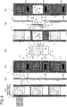
Fig. 8(a) is a plan view showing a printing tape in an unprinted state according to a variation aligning a longitudinal direction of a label with a tape length direction;Fig. 8(b) is a plan view showing a printed printing tape after an excess label portion has been peeled off;Fig. 8(c) is a side view of the structure shown inFig. 8(b); Fig. 8(d) is a rear view showing the printed printing tape;Fig. 8(e) is a cross-sectional view of the structure shown inFig. 8(a); and Fig. 8(f) is a cross-sectional view of the structure shown inFig. 8(b) . - [
Fig. 9 ]
Fig. 9(a) is a plan view showing the printed printing tape;Fig. 9(b) is a side view showing the structure shown inFig. 9(a); Fig. 9(c) is a rear view showing the printed printing tape;Fig. 9(d) is a plan view showing a state of the printed printing tape after single print label has been peeled off;Fig. 9(e) is a side view showing the structure shown inFig. 9(d); and Fig. 9(f) is a rear view of the printing tape after the print label has been peeled off. - [
Fig. 10 ]
Fig. 10(a) is a plan view showing a printing tape in an unprinted state according to a variation in which a plurality of columns of main label parts (print labels) is arranged in a tape width direction;Fig. 10(b) is a side view showing the structure shown inFig. 10(a); Fig. 10(c) is a rear view showing the structure shown inFig. 10(a); and Fig. 10(d) is a cross-sectional view of the structure shown inFig. 10(a) . - [
Fig. 11 ]
Fig. 11(a) is a plan view showing a printing tape in an unprinted state according to a variation using a tape of a continuous length type;Fig. 11(b) is a plan view showing a printed printing tape;Fig. 11(c) is a rear view shoeing the printed printing tape;Fig. 11(d) is a cross-sectional view showing the structure shown inFig. 11(a); and Fig. 11(e) is a cross-sectional view showing the structure shown inFig. 11(b) . - Below, embodiments of the present invention will be described with reference to
Fig. 1 through Fig. 7 . - First, the functional configuration of a label-creating device according to the present embodiment will be described with reference to
Fig. 1 . - In
Fig. 1 , a label-creating device 1 (corresponding to the printer) has acontrol circuit 2, an operation unit 3 on which the user (operator) can perform desired operations, a display unit 4 for displaying prescribed information, aRAM 5 for storing various information, a conveyingroller 6, aprint head 7, a cuttinglever 8, and acutter 9. - A
cartridge holder 12 is also provided in the label-creatingdevice 1. A tape cartridge 10 (corresponding to the cassette) is detachably mounted in thecartridge holder 12. Thetape cartridge 10 has acasing 11, and atape roll 10A (depicted in the drawing as concentric circles for simplification but actually wound into a roll) accommodated in thecasing 11. A printing tape To is wound in a roll shape to form thetape roll 10A. Here, thetape cartridge 10 may be a die-cut label type or a continuous length type (described later with reference toFig. 11 ). In the die-cut label type, a printing tape To having half-cuts HC (described later with reference toFig. 2 ) formed therein is wound about the tape roll A. In the continuous length type, a printing tape To having no half-cuts HC is wound about the tape roll A. Either type oftape cartridge 10 can be used in the label-creatingdevice 1. Unless otherwise stated, the following example describes a case of using the die-cut labeltype tape cartridge 10. The half-cuts HC are configured of perforations, for example. In this specification, a "perforation" denotes a plurality of holes provided intermittently in a fine line along the surface direction of a target layer, with each hole penetrating the target layer in the thickness direction (the same applies hereafter). - The
control circuit 2 is provided with a CPU and a ROM not shown in the drawings. Thecontrol circuit 2 executes various programs pre-stored in the ROM while utilizing the temporary storage function of theRAM 5 in order to perform overall control of the label-creatingdevice 1. - The conveying
roller 6 is disposed in opposition to theprint head 7. The printing tape To paid out from thetape roll 10A is interposed between the conveyingroller 6 andprint head 7. By rotating, the conveyingroller 6 conveys the printing tape To while pulling the printing tape To from thetape roll 10A. - The
print head 7 prints desired print objects (see the printed images R described later) on main label parts Lo (described later in greater detail) of the printing tape To conveyed by the conveyingroller 6. The print objects are user-specified characters, icons, and the like. - When actuated through a user operation on the cutting
lever 8, thecutter 9 cuts off a printed section of a printing tape T (described later in greater detail) having a plurality of print labels L formed along the conveying direction. Note that the printing tapes To and T correspond to the medium in the claims. -
Figs. 2(a) through 2(e) show the detailed structure of the printing tape To.Fig. 2(a) is a plan view showing the printing tape To in an unprinted state. The up-down direction in the drawing corresponds to the conveying direction (the tape length direction), the left-right direction in the drawing corresponds to the tape width direction, and the near-far direction in the drawing corresponds to the tape thickness direction.Fig. 2(b) shows a plan view of the printing tape T on which the printed image R has been printed and after an excess label portion has been peeled off.Fig. 2(c) is a rear view of the printed printing tape T.Fig. 2(d) is a cross-sectional view taken along the section IIx-IIx of the structure shown inFig. 2(a). Fig. 2(e) is a cross-sectional view taken along the section IIy-IIy of the structure shown inFig. 2(b) . - As shown in
Figs. 2(a) through 2(d) , the printing tape To includes an opaquerelease material layer 24, a transparent adhesive layer 22 (corresponding to an adhesive layer), and atransparent base layer 21 having compositions that include paper or colored film or fabric or metal. Therelease material layer 24,adhesive layer 22, andbase layer 21 are layered in sequence in the thickness direction (the depth direction in the perspective ofFig. 2(a) and Fig. 2(b) , the vertical direction inFig. 2(d) , and hence the direction in which each layer is laminated, as will be described later) from a first side of the thickness direction (the bottom inFig. 2(d) , the far side inFigs. 2(a) and 2(b) , and the near side inFig. 2(c) ) toward a second side of the thickness direction (the top inFig. 2(d) , the near side inFigs. 2(a) and 2(b) and the far side inFig. 2(c) ). Note that theadhesive layer 22 may be provided in part, rather than over the entire surface, on the back side (the bottom side inFig. 2(d) ) of thebase layer 21, i.e., between thebase layer 21 andrelease material layer 24. - In the printing tapes To and T having the layered structure described above, a plurality of main label parts Lo (or print labels L having a printed image R formed on each of the main label parts Lo) are arranged successively in the tape length direction (the up-down direction in the drawings) while separated by an excess label portion LB (see
Fig. 2(a) ). In other words, main label parts Lo (or print labels L) are arranged discretely along the tape length direction. These main label parts Lo (or print labels L) are all arranged with their longitudinal directions oriented in the tape width direction (left-right direction in the drawings). Thebase layer 21 is divided by the half-cuts HC (perforations) into the main label parts Lo and the remaining excess label portion LB and is fixed via theadhesive layer 22 to the surface on the second side of therelease material layer 24 in the thickness direction. The main label parts Lo correspond to the print label in the claims, and the excess label portion LB corresponds to the label in the claims. - At this time, a print background layer 25 (corresponding to a printing portion) is also partially provided on the front-side (the top in
Fig. 2(d) ) surface of thebase layer 21 at a position within the main label part Lo (seeFigs. 2(a), 2(b), 2(d), and 2(e) ). Theprint background layer 25 has a suitable non-transparent color and thethermal head 7 forms the printed image R therein. - Owing to the layered structure described above, each main label part Lo has a length Wb2 in the tape width direction and a width Wb1 in the tape length direction and includes three areas: an adhesive area D1 constituting the left end portion in the drawings; a non-adhesive area D23 provided adjacent to the adhesive area D1 and corresponding to the
print background layer 25; and an adhesive area D4 provided adjacent to the non-adhesive area D23. Here, a length Ws2 of the printing tapes To and T in the tape width direction is greater than the length Wb2 of the main label parts Lo in the tape width direction. - In the
release material layer 24, rectangular (square) slits S are formed. Each of these slits S is arranged such that the adhesive area D1 and adhesive area D4 are positioned in a slit outer area SO outside the slit S in a plan view, while the non-adhesive area D23 is positioned in a slit inner area SI inside the slit S in a plan view. - The
print background layer 25 is arranged with at least a portion overlapping at least a portion of the slit inner area SI enclosed by the slit S. In this example, the print background layers 25 have the same dimensions in the tape width direction and tape length direction as the slits S and the entirety of the print background layers 25 overlap areas AR within the corresponding slits S. In other words, the slits S overlap the print background layers 25 in a plan view. - Note that marks PM are provided on the
release material layer 24 in intermediate parts between neighboring slits S. The marks PM are used for positioning control when the conveyingroller 6 conveys the printing tape To. That is, the label-creatingdevice 1 is provided with a well-known reflective optical sensor (not illustrated) having a light-emitting unit and a light-receiving unit. During the positioning control, the optical sensor emits light from the light-emitting unit while the light-receiving unit receives light reflected off therelease material layer 24. At this time, the marks PM on therelease material layer 24 are detected based on the difference in the amount of light received between portions of therelease material layer 24 on which the marks PM are provided and all other portions, and the printing tape To is positioned based on these detections. - According to the structure of the
release material layer 24 described above, the rectangular slits S are juxtaposed on the printing tapes To and T along the up-down direction, and aprint background layer 25 is positioned in each slit inner area AR surrounded by a slit S. A printed image R is formed in theprint background layer 25 in each of the print labels L. The printed images R are print objects respectively configured of the text "A01," "A02," "A03," and the like in this example. The term "slit" in this specification denotes a cut penetrating the target layer in the thickness direction (the same applies hereafter). A configuration in which the target layer is partially cut in the thickness direction (the cut enters a fixed amount in the thickness direction) may be used in place of these slits (the same applies hereafter). - With the printing tapes To and T described above, first the excess label portion LB is separated from the main label parts Lo and the release material layer 24 (see
Figs. 2(b) and3(a) ) by peeling the excess label portion LB from the top surface of therelease material layer 24, as shown inFig. 2(a) . Note that a printing tape To may be provided with an initial configuration that omits the excess label portion LB fromFig. 2(a) (i.e., a configuration that omits printed images R fromFig. 2(b) ). Next, owing to the square-shaped slits S provided in therelease material layer 24 in advance, each print label L included on the printing tape T and having a printed image R formed on theprint background layer 25 as described above can be peeled off while leaving the square-shaped portion of therelease material layer 24 located inside the slit S (the portion included in the slit inner area AR) on theadhesive layer 22 side (i.e., with the square-shaped portion covering the adhesive layer 22), as shown inFig. 3(b) . In the following description, this peeled off portion will simply be called the "print label L" for convenience. After the print label L has been peeled off, a space (a window WD) will remain in the strip-likerelease material layer 24 inside the rectangular slit S, as illustrated inFig. 3(b) . - As described above, each slit S has a square shape. More specifically, as shown in
Fig. 3(b) , the slit S includes opposing sides configured of a side Sa (corresponding to the first side) and a side Sb (corresponding to the second side), and opposing sides configured of a side Sc (corresponding to the third side) and a side Sd (corresponding to the fourth side). The main label part Lo (i.e., the print label L after being printed; the same applies hereafter) is fixed to therelease material layer 24 so as to span across both the side Sa and the side Sb of the corresponding slit S. - In accordance with the structure of the slit S, the
print background layer 25 is formed in a square shape having aside 25a (corresponding to the ninth side, and corresponding to the side Sa of the slit S), aside 25b (corresponding to the tenth side, and corresponding to the side Sb of the slit S), aside 25c (corresponding to the eleventh side, and corresponding to the side Sc of the slit S), and aside 25d of the slit S (corresponding to the twelfth side, and corresponding to the side Sd of the slit S). - In accordance with the above configuration, the main label part Lo is formed in a square shape with opposing sides configured of a side La (corresponding to the fifth side) and a side Lb (corresponding to the sixth side), and opposing sides configured of a side Lc (corresponding to the seventh side) and a side Ld (corresponding to the eighth side). The side Lc and side Ld are parallel to the side Sc and side Sd of the slit S and within proximity (a distance within 3 mm, for example) of the same respectively. As described above, the excess label portion LB is connected to the sides Lc and Ld and sides La and Lb of each main label part Lo via half-cuts HC configured of perforations. However, between the sides Lc and Ld of the main label part Lo and the excess label portion LB only, the perforated half-cuts HC may be replaced with slits similar to the slits S described above. In this case, the printing tape To must be provided with the excess label portion LB to prevent the main label parts Lo or print labels L from flapping or peeling off the printing tape To while being conveyed through the label-creating
device 1 in the tape length direction. - Note that the
print background layer 25 may be smaller than the slit inner area AR enclosed by the slit S. More specifically, the side Sc of the slit S may be offset toward the side Ld of the main label part Lo rather than the side Lc of the main label part Lo, and side Sd of the slit S may be offset toward the side Lc of the main label part Lo rather than the side Ld of the main label part Lo. - In the present embodiment, the side La of the main label part Lo is on the side closer to the side Sa than the side Sb of the slit S, and the side Lb of the main label part Lo is on the side closer to the side Sb than the side Sa of the slit S, as illustrated in
Fig. 3(b) . - Additionally, the shortest distance b' between the side Sa of the slit S and the side La of the main label part Lo is greater than the shortest distance c' between the side Sb of the slit S and the side Lb of the main label part Lo. Further, the shortest distance a' between the side Sa and side Sb of the slit S is between one and three times the shortest distance b'.
- In the present embodiment, the side La of the main label part Lo is on the side closer to the
side 25a than theside 25b of theprint background layer 25, and the side Lb of the main label part Lo is on the side closer to theside 25b than theside 25a of theprint background layer 25, as illustrated inFig. 3(b) . Further, the shortest distance b between theside 25a of theprint background layer 25 and the side La of the main label part Lo is greater than the shortest distance c between theside 25b of theprint background layer 25 and the side Lb of the main label part Lo. Further, the shortest distance a between theside 25a andside 25b of theprint background layer 25 is between one and three times the shortest distance b. - Additionally, the shortest distance b between the
side 25a of theprint background layer 25 and the side La of the main label part Lo is greater than the shortest distance c between theside 25b of theprint background layer 25 and the side Lb of the main label part Lo. Further, the shortest distance a between theside 25a andside 25b of theprint background layer 25 is between one and three times the shortest distance b. - Next, the structure of the print label L generated as described above will be described with reference to
Figs. 4(a) and 4(b). Fig. 4(a) shows a plan view of one print label L separated as described above, andFig. 4(b) shows a cross-sectional view along the section IVB-IVB inFig. 4(a) . - As with the printing tape T described earlier, the print label L shown in
Figs. 4(a) and 4(b) has thetransparent base layer 21, the transparentadhesive layer 22, and the opaquerelease material layer 24 arranged in sequence along the thickness direction (the depth direction inFig. 4(a) and the left-right direction inFig. 4(b) ) from the left side to the right side inFig. 4(b) . Theprint background layer 25 having the printed image R is partially provided on the second side surface of thebase layer 21 relative to the thickness direction. The print label L is provided with the adhesive area D1, non-adhesive area D23, and adhesive area D4 described above from another side (the top in the drawing) of the tape length direction (corresponding to the first direction) toward one side (the bottom in the drawing) in the tape length direction. - In the adhesive area D1, the
base layer 21 andadhesive layer 22 are layered in order from the second side toward the first side of the thickness direction (from the left side to the right side inFig. 4(b) ). Thus, the entire region of the adhesive area D1 is provided with an adhesive property owing to theadhesive layer 22. Note that the adhesive area D1 is provided with a length L1 in the tape width direction. - In the non-adhesive area D23, the
print background layer 25 provided with the printed image R, thebase layer 21, theadhesive layer 22, and therelease material layer 24 are layered in order from the second side toward the first side of the thickness direction (from the left side to the right side inFig. 4(b) ). Thus, the entire area of the non-adhesive area D23 is non-adhesive, as the adhesive property of theadhesive layer 22 is inhibited by therelease material layer 24. In this example, theprint background layer 25 is formed by applying ink (an ink coating layer) of a suitable color (a light transmissive color in this example, including transparent colors) on thebase layer 21, and thethermal head 7 forms the printed image R, which is the text "A01," as described above. The non-adhesive area D23 has a length L3 in the tape width direction. - In the adhesive area D4, the
base layer 21 andadhesive layer 22 are layered in order from the second side toward the first side of the thickness direction (from the left side to the right side inFig. 4(b) ). Thus, the entire area of the adhesive area D4 is provided with an adhesive property through theadhesive layer 22. The adhesive area D4 has a length L4 in the tape width direction. - The entire surface of the print label L on the second side of the thickness direction corresponds to the front surface in the claims, and the entire surface of the print label L on the first side of the thickness direction corresponds to the back surface of the claims.
-
Fig. 5 shows a sample procedure for attaching the print label L to an object. In the example ofFig. 5 , the print label L is attached by wrapping the print label L around a cable-like (i.e., columnar-shaped) object 302 (hereinafter simply called a "cable 302" for convenience) having a diameter 2r. - As shown in
Fig. 5(a) , the print label L extends in the order: adhesive area D1 -> non-adhesive area D23 covered by the separated release material layer 24 -> adhesive area D4. (In other words, theadhesive layer 22 of the print label L is exposed in the adhesive areas D1 and D4, which are not covered by therelease material layer 24.) First, the adhesive area D1 and non-adhesive area D23 of the print label L are bent into a concave shape (not illustrated) so that therelease material layer 24 side (the right side inFig. 5(a) ) is on the inside. - Next, the
cable 302 is placed on the inside of the concave-shaped print label L, and the print label L is wrapped once around thecable 302 to form a cylindrical body encircling thecable 302, as shown inFig. 5(b) . Subsequently, the adhesive layer 22 (functioning as the second portion of the adhesive layer on the side of the second side in the claims) on theadhesive area D 1 positioned on the distal end and the adhesive layer 22 (functioning as the first portion of the adhesive layer on the side of the first side in the claims) on the adhesive area D4 are bonded together while aligning the positions of the twoadhesive layers 22 in the tape width direction (also known as butt-sealing). At this time, the length of therelease material layer 24 in the tape width direction is at least greater than or equal to the circumference 2πr of thecable 302. As a result, the print label L can be attached to thecable 302 so as to be rotatable about the same by wrapping the non-adhesive area D23 of the print label L around thecable 302 so that the print label L is in a non-adhering state, while fixing the shape of the print label L itself by bonding the twoadhesive layers 22 together. Hence, by leaving a portion of therelease material layer 24 on the main label part Lo when therelease material layer 24 is peeled off, theadhesive layer 22 of the print label L can be prevented from becoming fixed to thecable 302. - Thereafter, the remaining portion of the adhesive area D4 that was not used in the structure encircling the
cable 302 is wrapped in the direction of the arrow G indicated inFig. 5(b) so that the bonded portion of the adhesive area D1 and adhesive area D4 are on the inside (for example, the adhesive area D1 contacts a back-fold region Y, as indicated by an arrow Z). At this time, the adhesive area D4 is wrapped around the outer circumferential portion of the non-adhesive area D23 while covering the non-adhesive area D23 that constitutes the cylindrical body (seeFig. 5(c) ). Thus, by using the adhesive property of theadhesive layer 22 to affix the adhesive area D4 to the outer circumferential portion of the non-adhesive area D23, the operation for attaching the print label L to thecable 302 is complete. -
Fig. 6 shows a sample application of the print label L described above. In this example, a cable for use with a switching hub that relays information over a network, such as a wired LAN, is applied as thecable 302. Theswitching hub 300 inFig. 6 has eightslots 301 in each of a top row and a bottom row (a total of sixteen slots). - In the example of the drawing, plates PL indicating the ID names "A01" through "A08" are provided in sequence from the left to correspond to the eight
slots 301 in the top row, and plates PL indicating the ID names "A09" through "A16" are provided in sequence from the left to correspond to the eightslots 301 in the bottom row. - The
cable 302 must be appropriately connected to thecorresponding slot 301. To facilitate connections, the print label L described above is mounted on the end of eachcable 302 that is to be inserted into one of theconnector slots 301, and the printed image R formed on each print label L has the same content as the ID name for theslot 301 to which thecable 302 is to be connected. In other words, a print label L printed with the same text as the ID name on the plate PL of theslot 301 to which thecable 302 is to be connected is affixed to thecable 302. This clarifies the correlations betweenslots 301 andcables 302 that are to be connected to theslots 301, thereby preventing incorrect wiring. -
Fig. 7 schematically shows the attached state of the print label L on thecable 302. An axial center k of thecable 302 is also indicated in the drawing. According to the structure described above, the print label L is affixed to thecable 302 constituting the object so as to be rotatable about thecable 302. In the sample state shown inFig. 7(a) , theprint background layer 25 is arranged such that the printed image R of "A01" provided on theprint background layer 25 is facing the viewer of the drawing. Although the transparent adhesive area D4 is actually present so as to cover the outer circumferential side of the non-adhesive area D23, as depicted inFig. 5(c) , the adhesive area D4 has been omitted fromFig. 7(a) and Fig. 7(b) described later to prevent complicating the diagram and to facilitate understanding. The print label L can be shifted to the orientation shown inFig. 7(b) by rotating the print label L in the direction of the dashed arrow (i.e., a circumferential direction) from the state shown inFig. 7(a) . Similarly, if the printed image R is not easily readable when the print label L is fixed to thecable 302 in the position shown inFig. 7(b) , the print label L is rotatable as described above owing to therelease material layer 24. Accordingly, by rotating the print label L in the direction opposite that described above to the position shown inFig. 7(a) , the printed image R can be made visible. - In the present embodiment described above, when the
release material layer 24 is peeled off the main label part Lo as described with reference toFig. 3(b) , a square-shaped area of therelease material layer 24 positioned inside the slit S separates from the remaining portion of therelease material layer 24. Thus, this square-shaped area of therelease material layer 24 remains on the main label part Lo (the print label L) and covers theadhesive layer 22. As a result, when forming a cylindrical body around thecable 302 by wrapping the print label L around thecable 302 with the square-shapedrelease material layer 24 that covers theadhesive layer 22 positioned on the inside, as described above, theadhesive layer 22 in the cylindrical body can be prevented from adhering to thecable 302. Thus, the print label L can eb rotatably attached to the cable 30. - By using a portion of the
release material layer 24 to suppress adhesion according to the structure described above, this structure does not degrade due to stress incurred while being wrapped around the object, changes in ambient conditions, or aging, as occurs in the conventional method of coating theadhesive layer 24 with varnish or other non-adhesive material. Thus, theadhesive layer 24 does not become exposed and does not impede rotation. - If the
release material layer 24 were transparent and all other portions of the print label L were also transparent, the contents of the printed image R formed by the label-creatingdevice 1 could be difficult to see depending on the color of thecable 302. The print label L in the present embodiment can suppress such adverse effects by using an opaquerelease material layer 24 having a composition that includes paper or colored film or fabric or metal. - A particular feature of the present embodiment is that the excess label portion LB is connected to the sides Lc and Ld of the main label part Lo (the print label L) through the perforated half-cuts HC. This configuration can suppress the main label part Lo (the print label L) from peeling off the
release material layer 24 while being conveyed through the label-creatingdevice 1 better than if the main label part Lo (the print label L) were fixed to therelease material layer 24 without the excess label portion LB. - Another feature of the present embodiment is that a nontransparent
release material layer 24 can be achieved by configuring therelease material layer 24 of a composition that includes paper or colored film or fabric or metal. - The present invention is not limited to the embodiment described above but may be modified in various ways without departing from the spirit and technical concepts thereof. Such variations will be described below. In each of the following variations, parts equivalent to those in the present embodiment will be designated with the same reference numerals, and duplicate descriptions will be omitted or simplified as appropriate.
- As shown in
Figs. 8(a) through 8(d) of this variation, as in the present embodiment described above, the main label parts Lo (or the print labels L having printed images R formed on the corresponding main label parts Lo) are arranged in series on the printing tapes To and T while separated from each other by the excess label portion LB (seeFig. 2(a) ). Further, thebase layer 21 is separated between the main label parts Lo and the excess label portion LB by the half-cuts HC and is fixed to the second side surface of therelease material layer 24 in the thickness direction via theadhesive layer 22. - In this variation, the main label parts Lo or print labels L are arranged such that their longitudinal directions are aligned with the tape length direction of the printing tapes To and T. That is, a plurality of the slits S are provided in the
release material layer 24 along the tape length direction, and a plurality of main label parts Lo or print labels L are fixed to therelease material layer 24 along the tape length direction. Therelease material layer 24 is elongated in the tape length direction, which is parallel to the side Sc of each of the plurality of slits S. A plurality of sets that each comprise one slit S and one corresponding main label part Lo (print label L) is juxtaposed along this length direction. - Each main label part Lo has a length Wb in the tape width direction and three areas: the adhesive area D1, non-adhesive area D23, and adhesive area D4. The printing tapes To and T have a length Ws in the tape width direction that is greater than the length Wb of the main label part Lo in the tape width direction. As in the present embodiment described above, rectangular-shaped (square-shaped) slits S are provided in the
release material layer 24, and the print background layers 25 are arranged so that at least a portion of eachprint background layer 25 overlaps at least a portion of the slit inner area AR enclosed by the corresponding slit S. In this example, the slits S overlap the print background layers 25 in a plan view. Further, as in the present embodiment, marks PM are provided on therelease material layer 24 for positioning control when the printing tape To is conveyed. Each mark PM is provided in an intermediate part between two neighboring slits S, S (but in a plan view are positioned inside the main label part Lo or print label L, as illustrated inFig. 8(c) and Fig. 8(d) ). Also, as in the present embodiment, printed images R configured of the text "A01," "A02," and "A03" are formed on the print background layers 25 of the corresponding print labels L. - As in the present embodiment described above, with the printing tapes To and T of this variation, first the excess label portion LB is separated from the main label parts Lo and the release material layer 24 (see
Fig. 8(b) andFig. 9(a) ) by peeling the excess label portion LB from the top surface of therelease material layer 24, as shown inFig. 8(a) . Note that a printing tape To may be provided with an initial configuration that omits the excess label portion LB fromFig. 8(a) (i.e., a configuration that omits the printed images R fromFig. 8(b) ). Next, owing to the square-shaped slits S described above, each print label L having a printed image R formed on theprint background layer 25 can be peeled off while the square-shaped portion of therelease material layer 24 positioned inside the slit S remains covering therelease material layer 24, as illustrated inFig. 9(d) . After the print label L has been peeled off, a space (a window WD) will remain on the strip-likerelease material layer 24 inside the rectangular slit S, as illustrated inFig. 9(f) . - As in the present embodiment described above, each slit S has opposing sides configured of a side Sa (corresponding to the first side) and a side Sb (corresponding to the second side) and opposing sides configured of a side Sc (corresponding to the third side) and a side Sd (corresponding to the fourth side), as illustrated in
Figs. 9(d) through 9(f) . The main label part Lo (print label L) is fixed to therelease material layer 24 so as to span across both the side Sa and the side Sb of the corresponding slit S (seeFigs. 9(d) through 9(f) ). In accordance with the above structure, theprint background layer 25 is formed in a square shape having theside 25a (corresponding to the ninth side), theside 25b (corresponding to the tenth side), theside 25c (corresponding to the eleventh side), and theside 25d (corresponding to the twelfth side). In accordance with this structure, the main label part Lo is formed in a square shape having opposing sides configured of a side La (corresponding to the fifth side) and a side Lb (corresponding to the sixth side) and opposing sides configured of a side Lc (corresponding to the seventh side) and a side Ld (corresponding to the eighth side). The excess label portion LB described above is connected to the sides Lc and Ld and the sides La and Lb of the main label part Lo through the perforated half-cuts HC. Note that slits similar to the slits S described above may be provided in place of the perforated half-cuts HC only between the excess label portion LB and the sides La and Lb of the main label part Lo. However, in this case the printing tape To must be provided with the excess label portion LB described above. Also as described above, theprint background layer 25 may be smaller than the slit inner area AR enclosed in the corresponding slit S. - In this variation, the dimensional relationship among the main label parts and the slits and the structure of the print label L that is produced are similar to those in the embodiment and, hence, a description will not be repeated here.
- The present variation can obtain the same effects described in the present embodiment.
- In the structures of the present embodiment described above and the variation (1) thereof, a plurality of sets, each comprising one slit S and one corresponding main label part Lo (print label L), is provided on the
release material layer 24. The sets are arranged discretely on therelease material layer 24 at intervals in the tape length direction (with the excess label portion LB present between sets), but variation (1) is not limited to this configuration. That is, sets of slits S and main label parts Lo (print labels L) may be arranged adjacent to each other (with no gaps therebetween) on therelease material layer 24. This structure can also obtain the same effects described above. - As illustrated in
Fig. 10(a), Fig. 10(b), Fig. 10(c), and Fig. 10(d) that correspond toFig. 8(b), Fig. 8(c), Fig. 8(d), and Fig. 8(f) described above, the length of therelease material layer 24 may be widened in the tape width direction, and a plurality of columns (two columns in this example) of main label parts Lo (print labels L) may be arranged on therelease material layer 24 adj acent to each other in the tape width direction. In other words, a plurality of label bodies may be arranged along the tape length direction. Each label body has a plurality of sets (two sets in this example), each comprising a slit S and a main label part Lo (print label L), arranged adjacent to each other in the tape width direction. This variation can also obtain the same effects described above. - In this variation, a printing tape To without the half-cuts HC described above (known as a continuous length type) is wound into the tape roll A and accommodated in the
tape cartridge 10. -
Figs. 11(a) through 11(d) show a detailed structure of the printing tapes To and T in this variation. -
Fig. 11(a) is a plan view of an unprinted printing tape To;Fig. 11(b) is a plan view of the printing tape T after the printed image R has been printed;Fig. 11(c) is a rear view of the printed printing tape T;Fig. 11(d) is a cross-sectional view taken along the section XIx-XIx in the structure shown inFig. 11(a); and Fig. 11(e) is a cross-sectional view taken along the section XIy-XIy in the structure shown inFig. 11(b) . - As described above, the printing tapes To and T include an opaque
release material layer 24, a transparent adhesive layer 22 (corresponding to the adhesive layer), and atransparent base layer 21 having compositions that include paper or colored film or fabric or metal, as shown inFigs. 11(a) through 11(e) . Therelease material layer 24,adhesive layer 22, andbase layer 21 are layered in sequence from a first side of the thickness direction (the bottom inFig. 11(d) and Fig. 11(e) , the far side inFig. 11(a) and Fig. 11(b) , and the near side inFig. 11(c) ) toward a second side of the thickness direction (the top inFig. 11(d) and Fig. 11(e) , the near side inFig. 11(a) and Fig. 11(b) , and the far side inFig. 11(c) ). Thebase layer 21 is fixed to the surface of therelease material layer 24 on the second side in the thickness direction via theadhesive layer 22. - As described above, the
adhesive layer 22 may be provided in part, rather than over the entire surface, on the back side of thebase layer 21, i.e., between thebase layer 21 andrelease material layer 24. A print background layer 25 (corresponding to the printing layer) is also partially provided on the front-side (the top inFig. 11(d) and Fig. 11(e) ) surface of thebase layer 21. Theprint background layer 25 has a suitable nontransparent color and the printed image R formed by thethermal head 7. Theprint background layer 25 is a rectangular-shaped layer having anedge 25A (corresponding to the first edge) on one side (the right side inFig. 11(b) ), and anedge 25B (corresponding to the second edge) on the other side (the left side inFig. 11(b) ). The length of the printing tapes To and T in the tape width direction is the Wb2 described above. - A plurality of slits is provided in the
release material layer 24. The slits extend linearly in the tape length direction (corresponding to the first direction) from one short side of the rectangular release material layer 24 (the bottom inFig. 11(c) ) to the other short side (the top inFig. 11(c) ). In this example, therelease material layer 24 is provided with two slits, and specifically a slit S1 (corresponding to the first slit), and a slit S2 (corresponding to the second slit). In this case, thebase layer 21 is fixed to therelease material layer 24 via theadhesive layer 22 so as to span across both the slit S1 and the slit S2. - Here, the
print background layer 25 is disposed so that at least a portion of theprint background layer 25 overlaps at least a portion of the slit inner area AR enclosed by the slits S1 and S2. The dimension of theprint background layer 25 in the tape width direction is equal to or smaller than the same dimension of the slit inner area AR. In this example, theprint background layer 25 and the slit inner area AR have the same length in the tape width direction, and the entirety of theprint background layer 25 overlaps the slit inner area AR. In other words, the slit inner area AR overlaps theprint background layer 25 in a plan view. In this example, the printed images R formed on theprint background layer 25 of the printing tape T comprise print objects including the text "A01," "A02," "A03," .... Thebase layer 21,adhesive layer 22, andprint background layer 25 correspond to the print label layer in the claims. - As shown in
Fig. 11(b), Fig. 11(c), and Fig. 11(e) , oneedge 21a on one side (the right side in the drawings) of thebase layer 21 is on the side closer to the slit S1 than the slit S2, and anotheredge 21b on another side (the left side in the drawings) of thebase layer 21 is on the side closer to the slit S2 than the slit S1. Further, the shortest distance b' between the slit S1 and the oneedge 21a on the one side of thebase layer 21 is greater than the shortest distance c' between the slit S2 and theother edge 21b on the other side of thebase layer 21, and the shortest distance a' between the slit S1 and slit S2 is between one and three times the shortest distance b' between the slit S1 and the oneedge 21a on the one side of thebase layer 21. - Further, the one
edge 21a on the one side of thebase layer 21 is on the side closer to theedge 25A than theedge 25B of theprint background layer 25, and theother edge 21b on the other side of thebase layer 21 is on the side closer to theedge 25B than theedge 25A of theprint background layer 25. Further, the shortest distance b between theedge 25A of theprint background layer 25 and the oneedge 21a on the one side of thebase layer 21 is greater than the shortest distance c between theedge 25B of theprint background layer 25 and theother edge 21b on the other side of thebase layer 21, and the shortest distance a between theedge 25A andedge 25B of theprint background layer 25 is between one and three times the shortest distance b between theedge 25A of theprint background layer 25 and the oneedge 21a on the one side of thebase layer 21. - As described earlier, the layered structure for the printing tapes To and T described above has three regions, i.e., the adhesive area D1, the non-adhesive area D23 provided adjacent to the adhesive area D1 and corresponding to the
print background layer 25, and the adhesive area D4 provided adj acent to the non-adhesive area D23. By cutting the printing tape T with thecutter 9 after the printing tape T has been printed, the label-creatingdevice 1 can obtain a print label L having the width Wb1 in the tape length direction (depicted with two-dot chain lines inFig. 11 ) and substantially the same structure as described in the preferred embodiment and variation (1) (i.e., a structure similar to that inFig. 4 ). Accordingly, this variation can obtain the same effects described above. - When dimensions and sizes are described as being "identical," "equivalent," "different," and the like in appearance in the above description, these terms are not intended to be taken in their strictest sense. In other words, the terms "identical," equivalent," and different" may signify "substantially identical," "substantially equivalent," and "substantially different" to allow for design and manufacturing tolerances and error.
- The arrows shown in
Fig. 1 indicate an example of the signal flow in the above description, but the directions of signal flow are not limited to this example. - In addition to what has already been described, the methods according to the present embodiment and its variations may be used in suitable combinations.
- In addition, although not illustrated individually, the present invention may be implemented with various modifications without departing from the spirit of the invention.
-
- 1
- label-creating device (printer)
- 10
- tape cartridge (cassette)
- 21
- base layer
- 21a
- one edge on one side
- 21b
- another edge on another side
- 22
- adhesive layer (adhesive layer)
- 24
- release material layer
- 25
- print background layer (printing portion, printing layer)
- 25A
- edge on one side (first edge)
- 25B
- edge on the other side (second edge)
- 25a
- side (ninth side)
- 25b
- side (tenth side)
- 25c
- side (eleventh side)
- 25d
- side (twelfth side)
- AR
- slit inner area
- HC
- half-cut
- L
- print label
- La
- side (fifth side)
- Lb
- side (sixth side)
- Lc
- side (seventh side)
- Ld
- side (eighth side)
- Lo
- main label part (print label)
- LB
- excess label portion (label)
- R
- printed image
- S
- slit
- S1
- slit (first slit)
- S2
- slit (second slit)
- Sa
- side (first side)
- Sb
- side (second side)
- Sc
- side (third side)
- Sd
- side (fourth side)
- T
- printing tape (medium)
- To
- printing tape (medium)
Claims (20)
- A medium to be mounted in and to be printed with a printer, the medium comprising:a release material that is opaque;a slit provided in the release material and having a square shape including a first side, a second side, a third side, and a fourth side, the first side and the second side opposing each other, the third side and the fourth side opposing each other; anda print label fixed to the release material so as to span across the first side of the slit.
- The medium according to claim 1,
wherein the print label is fixed to the release material so as to span across both the first side and the second side of the slit. - The medium according to claim 2,
wherein the print label has a square shape including a fifth side, a sixth side, a seventh side, and an eighth side, the fifth side and the sixth side opposing each other, the seventh side and the eighth side opposing each other, and
wherein the seventh side and the eighth side of the print label are parallel to respective ones of the third side and the fourth side of the slit and within proximity of respective ones of the third side and the fourth side of the slit. - The medium according to claim 3,
wherein the third side of the slit is offset toward the eighth side of the print label rather than the seventh side of the print label, and
wherein the fourth side of the slit is offset toward the seventh side of the print label rather than the eighth side of the print label. - The medium according to claim 3,
wherein the fifth side of the print label is on a side closer to the first side of the slit than the second side of the slit,
wherein the sixth side of the print label is on a side closer to the second side of the slit than the first side of the slit,
wherein a shortest distance between the first side of the slit and the fifth side of the print label is greater than a shortest distance between the second side of the slit and the sixth side of the print label, and
wherein a shortest distance between the first side of the slit and the second side of the slit is equal to or greater than the shortest distance between the first side of the slit and the fifth side of the print label and is equal to or smaller than three times the shortest distance between the first side of the slit and the fifth side of the print label. - The medium according to claim 3,
wherein the print label comprises a printing portion having a square shape including a ninth side, a tenth side, an eleventh side, and a twelfth side, the ninth side and the tenth side opposing each other, the eleventh side and the twelfth side opposing each other,
wherein the fifth side of the print label is on a side closer to the ninth side of the printing portion than the tenth side of the printing portion,
wherein the sixth side of the print label is on a side closer to the tenth side of the printing portion than the ninth side of the printing portion,
wherein a shortest distance between the ninth side of the printing portion and the fifth side of the print label is greater than a shortest distance between the tenth side of the printing portion and the sixth side of the print label, and
wherein a shortest distance between the ninth side of the printing portion and the tenth side of the printing portion is equal to or greater than the shortest distance between the ninth side of the printing portion and the fifth side of the print label and is equal to or smaller than three times the shortest distance between the ninth side of the printing portion and the fifth side of the print label. - The medium according to claim 1,
wherein the print label comprises a printing portion having a shape and a size same as a shape and a size of an area enclosed by the slit. - The medium according to claim 1,
wherein the print label comprises a printing portion having a size smaller than a size of an area enclosed by the slit. - The medium according to claim 3, further comprising:
a label fixed to the release material and connected to the seventh side and the eight side of the print label via perforations. - A medium to be mounted in and to be printed with a printer, the medium comprising:a release material having a composition that includes paper or colored film or fabric or metal;a slit provided in the release material and having a square shape including a first side, a second side, a third side, and a fourth side, the first side and the second side opposing each other, the third side and the fourth side opposing each other; anda print label fixed to the release material so as to span across the first side of the slit.
- The medium according to claim 1 or claim 10,
wherein the slit comprises a plurality of slits each of which is provided in the release material,
wherein the print label comprises a plurality of print labels each of which is fixed to the release material corresponding to respective ones of the plurality of slits,
wherein the release material is elongated in a first direction parallel to the third side (Sc) of each of the plurality of slits, and
wherein a plurality of sets of slits and print labels is juxtaposed in the first direction on the release material, each of the plurality of sets of slits and print labels including one of the plurality of slits and corresponding one of the plurality of print labels. - The medium according to claim 11,
wherein the plurality of sets of slits and print labels are arranged adjacent to each other with no gaps therebetween. - A medium to be mounted in and to be printed with a printer, the medium comprising:a release material layer having a rectangular shape including a first short side on one side in a first direction and a second short side on another side in the first direction;at least two slits parallel to each other, each of the at least two slits extending in the first direction from the first short side to the second short side of the release material layer; anda print label layer fixed to the release material layer so as to span across the at least two slits,wherein the at least two slits include a first slit and a second slit.
- The medium according to claim 13,
wherein the print label layer has one edge on one side and another edge on another side, the one edge being on a side closer to the first slit than the second slit, the other edge being on a side closer to the second slit than the first slit,
wherein a shortest distance between the first slit and the one edge of the print label layer is greater than a shortest distance between the second slit and the other edge of the print label layer, and
wherein a shortest distance between the first slit and the second slit is equal to or greater than the shortest distance between the first slit and the one edge of the print label layer and is equal to or smaller than three times the shortest distance between the first slit and the one edge of the print label layer. - The medium according to claim 14,
wherein the print label layer comprises a printing layer having a rectangular shape including a first edge and a second edge, the first edge and the second edge opposing each other, the printing layer being arranged with at least a portion of the printing layer overlapping at least a portion of an area enclosed by the first slit and the second slit,
wherein the one edge of the print label layer is on a side closer to the first edge of the printing layer than the second edge of the printing layer,
wherein the other edge of the print label layer is on a side closer to the second edge of the printing layer than the first edge of the printing layer,
wherein a shortest distance between the first edge of the printing layer and the one edge of the print label layer is greater than a shortest distance between the second edge of the printing layer and the other edge of the print label layer, and
wherein a shortest distance between the first edge of the printing layer and the second edge of the printing layer is equal to or greater than the shortest distance between the first edge of the printing layer and the one edge of the print label layer and is equal to or smaller than three times the shortest distance between the first edge of the printing layer and the one edge of the print label layer. - The medium according to claim 13,
wherein the print label layer comprises a printing layer having a dimension in a second direction same as a dimension in the second direction of an area enclosed by the first slit and the second slit, the second direction being orthogonal to the first direction. - The medium according to claim 13,
wherein the print label layer comprises a printing layer having a dimension in a second direction smaller than a dimension in the second direction of an area enclosed by the first slit and the second slit, the second direction being orthogonal to the first direction. - The medium according to claim 13,
wherein the at least two slits are two slits. - The medium according to any one of claims 1 to 18,
wherein the medium has a roll shape, and is accommodated in a cassette to be detachably mounted in the printer. - A method of wrapping a label around a cable, the label having a front surface on which a printed image is formed and a back surface, the back surface including an adhesive layer on which a release material is fixed so that the adhesive layer is exposed, the release material having a square shape including a first side and a second side opposing each other, the adhesive layer having a first portion on a side of the first side of the release material and a second portion on a side of the second side of the release material, the first portion and the second portion being exposed, the method comprising:encircling the cable with the label so that the release material is on an inside; andbonding the first portion of the adhesive layer and the second portion of the adhesive layer together while aligning the first side and the second side in an encircling direction.
Applications Claiming Priority (2)
| Application Number | Priority Date | Filing Date | Title |
|---|---|---|---|
| JP2018184809A JP7555178B2 (en) | 2018-09-28 | 2018-09-28 | Media |
| PCT/JP2019/033465 WO2020066421A1 (en) | 2018-09-28 | 2019-08-27 | Medium and winding method |
Publications (2)
| Publication Number | Publication Date |
|---|---|
| EP3846152A1 true EP3846152A1 (en) | 2021-07-07 |
| EP3846152A4 EP3846152A4 (en) | 2022-09-28 |
Family
ID=69950444
Family Applications (1)
| Application Number | Title | Priority Date | Filing Date |
|---|---|---|---|
| EP19864811.5A Pending EP3846152A4 (en) | 2018-09-28 | 2019-08-27 | BACKING AND WINDING METHOD |
Country Status (5)
| Country | Link |
|---|---|
| US (1) | US12475814B2 (en) |
| EP (1) | EP3846152A4 (en) |
| JP (1) | JP7555178B2 (en) |
| CN (1) | CN112771596B (en) |
| WO (1) | WO2020066421A1 (en) |
Families Citing this family (2)
| Publication number | Priority date | Publication date | Assignee | Title |
|---|---|---|---|---|
| JP7555178B2 (en) | 2018-09-28 | 2024-09-24 | ブラザー工業株式会社 | Media |
| JP7148888B2 (en) | 2018-09-28 | 2022-10-06 | ブラザー工業株式会社 | medium |
Family Cites Families (39)
| Publication number | Priority date | Publication date | Assignee | Title |
|---|---|---|---|---|
| US4317852A (en) | 1980-07-21 | 1982-03-02 | Ralph Ogden | Label assembly with label end finger hold arrangement |
| JPS60152582A (en) * | 1984-01-18 | 1985-08-10 | Oji Paper Co Ltd | Release sheet |
| JPS6252028A (en) * | 1985-08-26 | 1987-03-06 | 株式会社日立製作所 | Automatic labeller |
| US5708462A (en) | 1988-06-22 | 1998-01-13 | Monarch Marking Systems, Inc. | Microprocessor controlled thermal printer |
| IE904260A1 (en) * | 1989-12-08 | 1991-06-19 | Kent Adhesive Prod Co | Adhesive laminate label array and method for making same |
| US5103583A (en) * | 1990-07-02 | 1992-04-14 | Ccl Product Identification, Inc. | Protected print label |
| FR2697206A1 (en) * | 1992-10-22 | 1994-04-29 | Moore Business Forms Inc | Packing label training set. |
| JPH08160864A (en) * | 1994-12-06 | 1996-06-21 | Lintec Corp | Tacky adhesive label |
| US5658648A (en) * | 1995-08-23 | 1997-08-19 | Wisconsin Label Corporation | Labels for electrical cord sets |
| US5958536A (en) | 1997-03-06 | 1999-09-28 | The Challenge Printing Company | Self-adhesive label with detachable sticker |
| US6177163B1 (en) * | 1998-06-22 | 2001-01-23 | Tricor Direct, Inc. | Markable repositionable adhesive sheet dispensing roll for use in an industrial setting |
| JP4684443B2 (en) | 2001-03-21 | 2011-05-18 | 株式会社サトー | Manufacturing method of partial adhesive labels for winding |
| WO2003098579A1 (en) | 2002-05-22 | 2003-11-27 | Honda Giken Kogyo Kabushiki Kaisha | Label, method of using the same, method of sticking and apparatus therefor |
| JP2004045812A (en) * | 2002-07-12 | 2004-02-12 | Brother Ind Ltd | Printing media and tape cassette containing the same |
| JP4359036B2 (en) | 2002-11-29 | 2009-11-04 | 株式会社サトー | Partially adhesive label and manufacturing apparatus thereof |
| US7225738B2 (en) | 2003-02-28 | 2007-06-05 | Hewlett-Packard Development Company, L.P. | Eye marks in image processing |
| JP2005001134A (en) | 2003-06-09 | 2005-01-06 | Canon Semiconductor Equipment Inc | Printing medium and printer |
| US7588811B2 (en) | 2004-03-19 | 2009-09-15 | Ncr Corporation | Columnar adhesive label roll |
| TW200729102A (en) | 2005-11-30 | 2007-08-01 | Max Co Ltd | Peel-off paper-attached label and label printer |
| JP5055755B2 (en) | 2005-11-30 | 2012-10-24 | マックス株式会社 | Label with release paper and label printer |
| JP4785050B2 (en) * | 2006-06-20 | 2011-10-05 | 小林クリエイト株式会社 | Label sheet |
| JP4883781B2 (en) | 2006-12-01 | 2012-02-22 | 小林クリエイト株式会社 | Label sheet |
| JP4781293B2 (en) | 2007-02-09 | 2011-09-28 | 小林クリエイト株式会社 | Label sheet |
| JP5187946B2 (en) * | 2008-03-12 | 2013-04-24 | 株式会社サトー知識財産研究所 | Label and label application method |
| US8263201B2 (en) * | 2008-05-09 | 2012-09-11 | Panduit Corp. | Self-laminating rotating cable marker label with breakaway portion |
| JP4856143B2 (en) | 2008-09-29 | 2012-01-18 | 株式会社サトー知識財産研究所 | Label with reattachment area |
| US20100127491A1 (en) * | 2008-11-25 | 2010-05-27 | Electronic Imaging Materials, Inc. | Laminate Labels |
| JP5347812B2 (en) | 2009-07-31 | 2013-11-20 | マックス株式会社 | Label with release paper, label printer, and label printing method |
| JP5515109B2 (en) | 2009-11-17 | 2014-06-11 | 株式会社フジシール | Sheet material transfer device |
| JP2011136514A (en) | 2009-12-28 | 2011-07-14 | Max Co Ltd | Label printer and storage medium |
| JP5556314B2 (en) | 2010-04-02 | 2014-07-23 | セイコーエプソン株式会社 | Print medium, wristband, and method for creating wristband |
| DE102011054505A1 (en) * | 2011-10-14 | 2013-04-18 | Andreas Gschwindt | Cable marking strips |
| JP6024426B2 (en) | 2012-12-04 | 2016-11-16 | ブラザー工業株式会社 | Printing medium and printing device |
| JP6203660B2 (en) | 2013-06-20 | 2017-09-27 | 株式会社Okiデータ・インフォテック | inkjet printer |
| JP6394526B2 (en) | 2015-07-24 | 2018-09-26 | ブラザー工業株式会社 | Tape and tape cartridge |
| JP6507906B2 (en) | 2015-07-24 | 2019-05-08 | ブラザー工業株式会社 | Tape cartridge and printing apparatus |
| JP7148888B2 (en) | 2018-09-28 | 2022-10-06 | ブラザー工業株式会社 | medium |
| JP7555178B2 (en) | 2018-09-28 | 2024-09-24 | ブラザー工業株式会社 | Media |
| JP7269549B2 (en) | 2019-03-26 | 2023-05-09 | ブラザー工業株式会社 | Labels and label printing methods |
-
2018
- 2018-09-28 JP JP2018184809A patent/JP7555178B2/en active Active
-
2019
- 2019-08-27 EP EP19864811.5A patent/EP3846152A4/en active Pending
- 2019-08-27 CN CN201980064009.XA patent/CN112771596B/en active Active
- 2019-08-27 WO PCT/JP2019/033465 patent/WO2020066421A1/en not_active Ceased
-
2021
- 2021-03-26 US US17/213,565 patent/US12475814B2/en active Active
Also Published As
| Publication number | Publication date |
|---|---|
| JP2020052381A (en) | 2020-04-02 |
| CN112771596A (en) | 2021-05-07 |
| WO2020066421A1 (en) | 2020-04-02 |
| JP7555178B2 (en) | 2024-09-24 |
| US12475814B2 (en) | 2025-11-18 |
| CN112771596B (en) | 2023-06-20 |
| US20210217329A1 (en) | 2021-07-15 |
| EP3846152A4 (en) | 2022-09-28 |
Similar Documents
| Publication | Publication Date | Title |
|---|---|---|
| EP3933813B1 (en) | Label and method of printing and attaching label | |
| US12319076B2 (en) | Medium used with printer and including label and mark provided on release material | |
| JP4308310B1 (en) | Price reduction label and its application method | |
| US12475814B2 (en) | Medium including release material, slit, and print label and method of wrapping the same | |
| CN106364175B (en) | Band and tape drum | |
| US11804153B2 (en) | Medium including release material and printing label and method of wrapping peeled-off label | |
| JP6970908B2 (en) | Long media and tape cartridges | |
| JP2016071238A (en) | Self-laminating printing tape, small roll, and self-laminating tape cassette | |
| US12534645B2 (en) | Tape cassette including tape and cover film, and method of creating labels with the tape cassette | |
| JP2019059869A (en) | Medium, roll medium, and medium cartridge | |
| JP2780110B2 (en) | label | |
| JP6895114B2 (en) | Medium and tape cartridges | |
| JP7234588B2 (en) | Packaging materials for medical equipment | |
| JP2004133364A (en) | Linerless label | |
| WO2020065702A1 (en) | Long medium and tape cartridge |
Legal Events
| Date | Code | Title | Description |
|---|---|---|---|
| STAA | Information on the status of an ep patent application or granted ep patent |
Free format text: STATUS: THE INTERNATIONAL PUBLICATION HAS BEEN MADE |
|
| STAA | Information on the status of an ep patent application or granted ep patent |
Free format text: STATUS: REQUEST FOR EXAMINATION WAS MADE |
|
| PUAI | Public reference made under article 153(3) epc to a published international application that has entered the european phase |
Free format text: ORIGINAL CODE: 0009012 |
|
| 17P | Request for examination filed |
Effective date: 20210330 |
|
| AK | Designated contracting states |
Kind code of ref document: A1 Designated state(s): AL AT BE BG CH CY CZ DE DK EE ES FI FR GB GR HR HU IE IS IT LI LT LU LV MC MK MT NL NO PL PT RO RS SE SI SK SM TR |
|
| DAV | Request for validation of the european patent (deleted) | ||
| DAX | Request for extension of the european patent (deleted) | ||
| A4 | Supplementary search report drawn up and despatched |
Effective date: 20220830 |
|
| RIC1 | Information provided on ipc code assigned before grant |
Ipc: G09F 3/20 20060101ALI20220824BHEP Ipc: H02G 1/06 20060101ALI20220824BHEP Ipc: G09F 3/02 20060101AFI20220824BHEP |
|
| P01 | Opt-out of the competence of the unified patent court (upc) registered |
Effective date: 20230529 |
|
| STAA | Information on the status of an ep patent application or granted ep patent |
Free format text: STATUS: EXAMINATION IS IN PROGRESS |
|
| 17Q | First examination report despatched |
Effective date: 20240926 |