EP3845930A1 - Passive security checking device and receiving antenna unit thereof - Google Patents
Passive security checking device and receiving antenna unit thereof Download PDFInfo
- Publication number
- EP3845930A1 EP3845930A1 EP20216169.1A EP20216169A EP3845930A1 EP 3845930 A1 EP3845930 A1 EP 3845930A1 EP 20216169 A EP20216169 A EP 20216169A EP 3845930 A1 EP3845930 A1 EP 3845930A1
- Authority
- EP
- European Patent Office
- Prior art keywords
- horn
- waveguide
- checking device
- receiving antenna
- passive security
- Prior art date
- Legal status (The legal status is an assumption and is not a legal conclusion. Google has not performed a legal analysis and makes no representation as to the accuracy of the status listed.)
- Granted
Links
Images





Classifications
-
- H—ELECTRICITY
- H01—ELECTRIC ELEMENTS
- H01Q—ANTENNAS, i.e. RADIO AERIALS
- H01Q21/00—Antenna arrays or systems
- H01Q21/0006—Particular feeding systems
- H01Q21/0012—Radial guide fed arrays
-
- G—PHYSICS
- G01—MEASURING; TESTING
- G01V—GEOPHYSICS; GRAVITATIONAL MEASUREMENTS; DETECTING MASSES OR OBJECTS; TAGS
- G01V8/00—Prospecting or detecting by optical means
- G01V8/005—Prospecting or detecting by optical means operating with millimetre waves, e.g. measuring the black losey radiation
-
- H—ELECTRICITY
- H01—ELECTRIC ELEMENTS
- H01Q—ANTENNAS, i.e. RADIO AERIALS
- H01Q1/00—Details of, or arrangements associated with, antennas
- H01Q1/12—Supports; Mounting means
- H01Q1/22—Supports; Mounting means by structural association with other equipment or articles
- H01Q1/225—Supports; Mounting means by structural association with other equipment or articles used in level-measurement devices, e.g. for level gauge measurement
-
- H—ELECTRICITY
- H01—ELECTRIC ELEMENTS
- H01Q—ANTENNAS, i.e. RADIO AERIALS
- H01Q13/00—Waveguide horns or mouths; Slot antennas; Leaky-waveguide antennas; Equivalent structures causing radiation along the transmission path of a guided wave
- H01Q13/02—Waveguide horns
-
- H—ELECTRICITY
- H01—ELECTRIC ELEMENTS
- H01Q—ANTENNAS, i.e. RADIO AERIALS
- H01Q13/00—Waveguide horns or mouths; Slot antennas; Leaky-waveguide antennas; Equivalent structures causing radiation along the transmission path of a guided wave
- H01Q13/02—Waveguide horns
- H01Q13/0208—Corrugated horns
- H01Q13/0225—Corrugated horns of non-circular cross-section
-
- H—ELECTRICITY
- H01—ELECTRIC ELEMENTS
- H01Q—ANTENNAS, i.e. RADIO AERIALS
- H01Q19/00—Combinations of primary active antenna elements and units with secondary devices, e.g. with quasi-optical devices, for giving the antenna a desired directional characteristic
- H01Q19/06—Combinations of primary active antenna elements and units with secondary devices, e.g. with quasi-optical devices, for giving the antenna a desired directional characteristic using refracting or diffracting devices, e.g. lens
- H01Q19/062—Combinations of primary active antenna elements and units with secondary devices, e.g. with quasi-optical devices, for giving the antenna a desired directional characteristic using refracting or diffracting devices, e.g. lens for focusing
-
- H—ELECTRICITY
- H01—ELECTRIC ELEMENTS
- H01Q—ANTENNAS, i.e. RADIO AERIALS
- H01Q19/00—Combinations of primary active antenna elements and units with secondary devices, e.g. with quasi-optical devices, for giving the antenna a desired directional characteristic
- H01Q19/10—Combinations of primary active antenna elements and units with secondary devices, e.g. with quasi-optical devices, for giving the antenna a desired directional characteristic using reflecting surfaces
- H01Q19/104—Combinations of primary active antenna elements and units with secondary devices, e.g. with quasi-optical devices, for giving the antenna a desired directional characteristic using reflecting surfaces using a substantially flat reflector for deflecting the radiated beam, e.g. periscopic antennas
-
- H—ELECTRICITY
- H01—ELECTRIC ELEMENTS
- H01Q—ANTENNAS, i.e. RADIO AERIALS
- H01Q19/00—Combinations of primary active antenna elements and units with secondary devices, e.g. with quasi-optical devices, for giving the antenna a desired directional characteristic
- H01Q19/10—Combinations of primary active antenna elements and units with secondary devices, e.g. with quasi-optical devices, for giving the antenna a desired directional characteristic using reflecting surfaces
- H01Q19/18—Combinations of primary active antenna elements and units with secondary devices, e.g. with quasi-optical devices, for giving the antenna a desired directional characteristic using reflecting surfaces having two or more spaced reflecting surfaces
- H01Q19/19—Combinations of primary active antenna elements and units with secondary devices, e.g. with quasi-optical devices, for giving the antenna a desired directional characteristic using reflecting surfaces having two or more spaced reflecting surfaces comprising one main concave reflecting surface associated with an auxiliary reflecting surface
- H01Q19/195—Combinations of primary active antenna elements and units with secondary devices, e.g. with quasi-optical devices, for giving the antenna a desired directional characteristic using reflecting surfaces having two or more spaced reflecting surfaces comprising one main concave reflecting surface associated with an auxiliary reflecting surface wherein a reflecting surface acts also as a polarisation filter or a polarising device
-
- H—ELECTRICITY
- H01—ELECTRIC ELEMENTS
- H01Q—ANTENNAS, i.e. RADIO AERIALS
- H01Q21/00—Antenna arrays or systems
-
- H—ELECTRICITY
- H01—ELECTRIC ELEMENTS
- H01Q—ANTENNAS, i.e. RADIO AERIALS
- H01Q21/00—Antenna arrays or systems
- H01Q21/06—Arrays of individually energised antenna units similarly polarised and spaced apart
- H01Q21/08—Arrays of individually energised antenna units similarly polarised and spaced apart the units being spaced along or adjacent to a rectilinear path
Definitions
- the present disclosure relates to a passive security checking device, in particular, a receiving antenna unit for a passive security checking device, and a passive security checking device including the receiving antenna unit.
- Human security checking technology based on passive millimeter wave or terahertz wave has unique advantages: it achieves imaging by detecting the millimeter wave or terahertz wave of objects themselves due to good penetrability of millimeter wave or terahertz wave, thereby judging suspicious objects without active radiation, which is absolutely safe to human body.
- the passive security checking device generally uses a direct detector based on normal temperature.
- a antenna at the front end of the detector uses a conventional horn antenna.
- the horn antenna is characterized in that it can obtain symmetrical wave beams, that is, primary wave beams in planes E and H have angles which are substantially equal to each other in the directional diagram. Since 3dB wave beam angle of the horn antenna is inversely proportional to the antenna aperture thereof. As the coupling efficiency becomes higher, the antenna aperture becomes larger. In such a case, fewer horn antennae can be arranged per focal spot as the antenna aperture becomes larger, thereby forming a contradiction between the coupling efficiency and sampling interval in a quasi-optical system.
- the conventional horn antenna is used as a feed source of a radiometer with the following feature: the coupling efficiency of the antenna with the lens is low, usually less than 50%.
- a receiving antenna unit for a passive security checking device comprising at least one horn antenna comprising a horn body and a waveguide connected to the horn body, and a ratio of a long side to a short side of an horn opening of the horn body is greater than 1.2.
- a plurality of horn antennae are one-dimensionally arranged or arranged in an arc in a direction of the short side of the horn opening of the horn body.
- the waveguide is a rectangular waveguide.
- the ratio of the long side to the short side of the horn opening of the horn body is not less than 1.5.
- the ratio of the long side to the short side of the horn opening of the horn body is not more than 5.
- a height of the horn body is H that is not less than a length of the long side of the horn opening of the horn body.
- the long side of the horn opening of the horn body corresponds to a long side of the waveguide.
- the short side of the horn opening of the horn body corresponds to a long side of the waveguide.
- a passive security checking device comprising: an optical means for reflecting and converging millimeter wave/terahertz waves spontaneously radiated by an object under check and millimeter wave/terahertz waves reflected by background environment; and a detector array for receiving converged millimeter waves/terahertz waves and converting the received millimeter waves/terahertz waves into electrical signals, the detector array comprising the receiving antenna unit as described above.
- a polarization direction of the horn antenna is horizontal polarization.
- a detector in the detector array comprises a normal temperature direct detector comprising a coplanar line and a transition waveguide for inputting millimeter waves/terahertz waves, the polarization direction of the waveguide of the horn antenna being configured to be horizontal polarization, the polarization direction of a waveguide port surface of the waveguide of the horn antenna matching the polarization direction of a waveguide port surface of the transition waveguide; and/or a polarization direction from the transition waveguide to the coplanar line matches the polarization direction of the waveguide of the horn antenna.
- a detector in the detector array comprises a normal temperature heterodyne mixing demodulation detector comprising a local oscillator input waveguide and a radio frequency input waveguide, a polarization direction of the waveguide of the horn antenna being configured to be horizontal polarization, a polarization direction of a waveguide port surface of the waveguide of the horn antenna matching a polarization direction of a waveguide port surface of the radio frequency input waveguide; and/or a polarization direction of the local oscillator input waveguide matches the polarization direction of the waveguide of the horn antenna.
- the passive security checking device further comprises: a data collecting and processing means that is connected to the detector array to receive electrical signals from the detector array and generate a millimeter wave/terahertz wave image; and a display that is connected to the data collecting and processing means, for receiving and displaying the generated millimeter wave/terahertz wave image from the data collecting and processing means.
- the passive security checking device is a human passive security instrument.
- a receiving antenna unit for a passive security checking device includes at least one horn antenna including a horn body and a waveguide connected to the horn body, and a ratio of a long side to a short side of a horn opening of the horn body is greater than 1.2.
- a passive security checking device includes: an optical means for reflecting and converging millimeter wave/terahertz waves radiated by an object under check and millimeter wave/terahertz waves reflected by background environment; and a detector array for receiving converged millimeter waves/terahertz waves and converting the received millimeter waves/terahertz waves into electrical signals, the detector array including the above receiving antenna unit.
- Fig. 1 is a schematic structural diagram of a passive security checking device according to an exemplary embodiment of the present disclosure.
- the passive security checking device includes a reflecting plate 2 and a servo system thereof, a lens 3, a detector array 4, a data collecting and processing means 6, a display 7 and a distribution box 5.
- Terahertz waves or millimeter waves
- terahertz waves or millimeter waves
- the detector array 4 converts the received Terahertz waves (or millimeter waves) into electrical signals.
- the data collecting and processing means 6 is connected to the detector array 4 to receive the electrical signals from the detector array 4 and generate a millimeter wave/terahertz wave image.
- the display 7 is connected to the data collecting and processing means 6, to receive and display the millimeter wave/terahertz wave image generated by the data collecting and processing means 6.
- the distribution box 5 is configured to supply power to the whole passive security checking device.
- Fig. 2 is a diagram illustrating an operation principle of a passive security checking device according to an exemplary embodiment of the present disclosure.
- Fig. 3 is an operation flowchart of a passive security checking device according to an exemplary embodiment of the present disclosure.
- the servo system of the reflecting plate 2 controls the reflecting plate 2 to reciprocate, and the reciprocal of a period T of the movement is the imaging frame rate s.
- the swing angle is equal to ⁇ , to complete scanning at the angle of field that is equal to 2 ⁇ in a height direction within a range of the depth of field.
- the reflecting plate 2 forms an image from the maximum elevation angle to the minimum elevation angle.
- the data collecting and processing means 6 has been collecting data in this process.
- the control system of the reflecting plate 2 for example, may be equipped with a position encoder to feed back scanning positions of the reflecting plate with high precision.
- the data collecting and processing means 6 When collecting data, the data collecting and processing means 6 first marks the collected data according to the information of the position encoder for distinguishing the data of the next image, then the data collecting and processing means 6 performs digital filtering and image reconstruction to the collected data to generate a millimeter wave image. Then, after performing image denoising and enhancement to the image, the data collecting and processing means 6 transfers the image data to the display 7, so that the image may be displayed, suspicious objects may be labeled and automatic alarm may be performed on the display 7.
- the receiving antenna unit for the passive security checking device includes a plurality of horn antennae 410, wherein the horn antenna 410 includes a horn body 411 and a waveguide 412 connected to the horn body 411.
- a ratio of the long side to the short side of a horn opening of the horn body 411 is greater than 1.2.
- the plurality of horn antennas 410 are one-dimensionally arranged or arranged in an arc in a direction of the short side of the horn opening of the horn body 411, that is, short sides of the plurality of horn openings may be arranged into two parallel straight lines or two parallel curves.
- the waveguide 412 is a rectangular waveguide. It should be noted that those skilled in the art should understand that in some other embodiments of the present disclosure, the waveguide 412 may also have other shapes, such as circle.
- the long side a1 of the horn opening of the horn antenna 410 corresponds to the long side a of the rectangular waveguide.
- the ratio of the long side a1 to the short side b1 of the horn opening of the horn antenna 410 is greater than 1.2, preferably ⁇ 1.5.
- the size of the long side a1 depends on the resolution required by the system with ensuring the radiation performance of the horn antenna, and the short side b1 depends on the radiometer interval satisfying Rayleigh sampling, generally a1>a, b1>b; wherein a and b are the long side and the short side of the rectangular waveguide 412, respectively.
- the ratio of the long side a1 to the short side b1 of the horn antenna 410 should not be too large, otherwise, the resolution will be sacrificed. Typically, a1/b1 ⁇ 5.
- the height H of the horn body of the horn antenna 400 typically meets H ⁇ a1, preferably H is in the range of 1.2a1 to 1.5a1, or 1.5a1 to 2a1, or 2a1 to 3a1, for example, H is equal to 1.5a1, 2a1, and so on.
- the short side b2 of the horn opening of the horn antenna 410 corresponds to the long side a of the rectangular waveguide.
- the ratio of the long side a2 to the short side b2 of the horn opening of the horn antenna 410 is greater than 1.2, preferably ⁇ 1.5.
- the size of the long side a2 depends on the resolution required by the system with ensuring the radiation performance of the horn antenna 410, and the short side b2 depends on the radiometer interval satisfying Rayleigh sampling, generally a2>b, b2>a; wherein a and b are the long side and the short side of the rectangular waveguide 412, respectively.
- the ratio of the long side a2 to the short side b2 of the horn antenna 410 should not be too large, otherwise, the resolution will be sacrificed.
- the height H of the horn body of the horn antenna 400 typically meets H ⁇ a2, preferably H is in the range of 1.2a2 to 1.5a2, or 1.5a2 to 2a2, or 2a2 to 3a2, for example, H is equal to 1.5a2, 2a2, and so on.
- G A r ⁇ max( f ( ⁇ , ⁇ )) Therefore, it is quite effective to increase the power P received by the detector by increasing the gain of the receiving antenna.
- the horn antenna its gain increases as its size does.
- the sampling rate of the antenna array of the same length decreases.
- the coupling efficiency of the horn antenna with the lens decreases as the wave beam angle increases (
- Fig. 6 is a diagram illustrating the coupling process of the horn antenna with the lens.
- FIG. 7 is a diagram illustrating the coupling efficiency of the horn antenna with the lens). Therefore, the power coupling efficiency of the horn antenna with the optical system and the sampling interval are contradictory with each other.
- it is necessary to increase the gain of the horn antenna that is, to arrange as many antennae as possible in a certain area while increasing its aperture, which relates to designs of antenna size and arrangement.
- the receiving antenna unit provided by the present disclosure adopts a bar-shaped horn antenna 410, so that the beam width in the direction of its long side may be effectively compressed, its 3dB beam angle is small, and it has a higher coupling efficiency when applied in combination with a lens.
- adequate antennas with the advantage of short size may be arranged, so that the sampling rate requirements may be satisfied. That is, the horn antenna reduces the overflow energy as much as possible in one dimension under the condition that it meets the sampling rate requirements in another dimension such that a better compromise effect can be obtained.
- the hardware cost of the system can be greatly reduced by using one-row detector arrangement.
- the detector array is arranged in the direction of the short side to achieve Rayleigh sampling, i.e., only one sampling is performed within one 3dB wave beam width, so that the coupling efficiency of the receiving antenna with the lens achieves nearly 50% in the direction of the short side and over 90% in the direction of the long side, thereby improving the overall coupling efficiency, the signal-to-noise ratio of the system and the imaging quality.
- Fig. 8 is a directional diagram of a W-waveband horizontally polarized bar-shaped horn antenna of 6x18x30mm.
- Fig. 9 is a diagram illustrating the distribution of spots on the focal plane of the horn antenna according to the present disclosure after passing through the lens. It can be seen from Fig. 9 that the spots are distributed in an ellipse, and has a larger size in the direction of scanning.
- Table 1 shows the coupling efficiencies of a normal horn antenna and the bar-shaped horn antenna of the present disclosure with the same lens at the same passage spacing.
- Table 1 Antenna size 6X4.9X15mm 6X18X30mm Type of horn antenna Normal horn antenna Horn antenna of the present disclosure 3dB wave beam width Plane E 35.51° Plane E 28.02° Plane H 34.3° Plane H 18.78° gain 14.57dBi 18.16dBi Positive-feed coupling efficiency 50.2% 72.08%
- an elliptical beam spot is formed with the focusing of the polarization-enhanced bar-shaped horn antenna and being converged by the lens (as shown in Fig. 9 ), i.e., the beam spot is larger in the height direction and smaller in the horizontal direction. Then the entire field of view is sampled by scanning (as shown in Fig. 10 ).
- the spot in this form may be used for compensating for asymmetry of the spatial resolution caused by oversampling in the height direction and Rayleigh sampling in the array direction.
- the receiving antenna may effectively receive the signal. Otherwise the quality of the received signal will be deteriorated, or even no signal may be received at all. This phenomenon is called polarization mismatch.
- the detector uses a rectangular waveguide, its polarization direction is determined by the direction of the waveguide port.
- the short side of the waveguide port parallel to the ground is defined as horizontal polarization, and the long side parallel to the ground plane is defined as vertical polarization.
- the process of the thermal radiation detector from the human body or suspicious object can be divided into two steps: the first step is the process from the human body or suspicious object to the receiving antenna, and the second step is the transmission process of the detector content signal.
- the thermal radiation of the human body or the suspicious object in the terahertz band penetrates the clothing, reaches the reflecting plate and is reflected to the lens, then penetrates the front and back surfaces of the lens, and is finally received by the receiving antenna at the front end of the detector.
- ⁇ i is the angle of incidence
- n is the received refractivity
- R ⁇ is always greater than R // , that is, the transmissivity of the parallel polarization component is greater. Reflection occurs at four locations: clothing, the reflecting plate, the front and rear surfaces of the lens, resulting in that at the receiving antenna, the power of the horizontal polarization component should be greater than that of the vertical polarization component.
- a horizontally polarized antenna is selected as the antenna at the front end of the detector.
- polarization matching at two positions is involved here: at first position, the polarization direction of the rectangular waveguide of the horn antenna needs to be matched as horizontal polarization, and the polarization directions of the waveguide port surface 412A of the rectangular waveguide 412 of the horn antenna 410 and the waveguide port surface 422A of the transition waveguide section 422 need to match each other; at second position, the polarization direction from the transition waveguide section 422 to the coplanar line 421 also needs to match. If a polarization mismatch occurs at either or both of the two positions, the power transmission efficiency may be seriously affect, resulting in a low signal-to-noise ratio.
- the signal received by the receiving antenna is transferred to the mixer 426 through RF input waveguide 423, and then passes through an intermediate frequency amplifier and filter 427, finally demodulated by the demodulator.
- polarization matching at two positions is involved here: at first position, the polarization direction of the waveguide of the horn antenna 410 needs to be matched as horizontal polarization, and the polarization directions of the waveguide port surface 412A of the rectangular waveguide 412 of the horn antenna 410 and the waveguide port surface 423A of the RF input waveguide 423 need to match each other; at second position, the polarization direction of the local oscillator input waveguide 424 also needs to match. If a polarization mismatch occurs at either or both of the two positions, the power transmission efficiency may be seriously affect, resulting in a low signal-to-noise ratio.
- the detector array 4 includes a detector support 430 and a plurality of detectors 420 that are mounted on the detector support 430 and arranged in an arc, and the radius of curvature of the arc is selected to be 0.8 to 1.2 times the image distance.
- the detector array 4 is placed on the focal plane of the lens 3.
- the arrangement in an arc may be segmented into polylines.
- a passive security checking device includes an optical means for reflecting and converging millimeter wave/terahertz waves spontaneously radiated by an object under check and millimeter wave/terahertz waves reflected by background environment; and a detector array 4 for receiving converged millimeter waves/terahertz waves and converting the received millimeter waves/terahertz waves into electrical signals, the detector array 4 including the above receiving antenna unit.
- the optical means of the passive security checking device includes a grid-type reflecting plate 2 for reflecting terahertz waves (or millimeter waves) spontaneously radiated by the object under check and terahertz waves (or millimeter waves) reflected by the background environment, wherein the distribution of the grids 202 on the grid-type reflecting plate 2 matches the polarization direction of the receiving antennae of the detectors in the detector array 4.
- the receiving antenna of the detector of the passive security checking device based on normal temperature detector is typically linearly polarized.
- the spontaneous radiation of the human body and the suspicious object is non-polarized.
- the linearly polarized receiving antenna can only detect the spontaneous radiation component that matches its polarization direction, while the reflexive radiation component orthogonal to its polarization direction cannot be detected but reflected by the receiving antenna.
- the reflected wave becomes the noise of the system and reduces the temperature sensitivity of the system, affecting the final image quality and identification of suspicious objects.
- the passive security checking device of the present disclosure adopts the grid-type reflecting plate 2, and the distribution of the grids 202 on the grid-type reflecting plate 2 matches the polarization direction of the receiving antennae of the detector array 4, so as to perform polarization selection to the reflecting plate 2, thereby improving the signal-to-noise ratio of the system, the temperature sensitivity of the system, and the image quality and identification of suspicious objects.
- the grid-type reflecting plate 2 may reduce the weight of the reflecting plate 2 and reduce the wind resistance of the swing of the reflecting plate 2, particularly in a case where the imaging speed is greater than 10 Hz.
- the grid-type reflecting plate 2 includes a substrate 201 and a plurality of metal grids 202 arranged on the substrate 201, wherein the plurality of metal grids 202 are periodically arranged in one dimension, for example, horizontally or vertically.
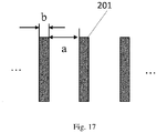
- Fig. 17 illustrates the arrangement of the grids 202, wherein a is the spacing between the metal grids 202 and b is the width of the metal grid 202. Specifically, the sizes of a and b depend on a balance among desired reflectivity, wind resistance, and weight.
- the arrangement direction of the metal grid 202 may also certainly be the arrangement direction of the detector array.
- the polarization direction of the antenna and the arrangement direction of the metal grid 202 both are the arrangement direction of the detector array.
- the arrangement direction of the metal grid 202 may also certainly be the orthogonal direction of the arrangement of the detector array.
- the polarization direction of the antenna and the arrangement direction of the metal grid 202 both are the orthogonal direction of the arrangement of the detector array.
- Table 2 summarizes the reflectivity of vertical polarization and horizontal polarization with different a, b parameters. Table 2 Distance between grids a Grid width b R vertical polarization R parallel polarization Example 1 Lam/10 a/5 >0.97 ⁇ 0.023 Example2 Lam/4 a/5 >0.84 ⁇ 0.0085 Example3 Lam/5 a/5 >0.89 ⁇ 0.007 Example4 Lam/5 a/3 >0.95 ⁇ 0.002 Example5 Lam/5 a/2 >0.987 ⁇ 0.1 Example6 Lam/3 a/2 >0.962 ⁇ 0.19
- the shape of the grid-type reflecting plate 2 includes, but is not limited to, a circle, an ellipse, a square, a rectangle, and a polygon.
- the lens 3 of the optical means may be a focusing reflecting plate, such as an ellipsoidal mirror, a Cassegrain reflector, etc.
- the focusing reflecting plate may also be a grid-type reflecting plate.
- Fig. 23 is a schematic structural diagram of a passive security checking device according to another exemplary embodiment of the present disclosure.
- the optical means may also adopt a polyhedral mirror 2' instead of the reflecting plate 2.
- the polyhedron mirror 2' includes a plurality of reflecting plates for reflecting terahertz waves (or millimeter waves) spontaneously radiated by the object under check and terahertz waves (or millimeter waves) reflected by the background environment, at least one of the plurality of reflecting plates being a grid-type reflecting plate.
- a passive security checking device includes an optical means for reflecting and converging millimeter wave/terahertz waves spontaneously radiated by an object under check and millimeter wave/terahertz waves reflected by background environment; and a detector array 4 for receiving converged millimeter waves/terahertz waves and converting the received millimeter waves/terahertz waves into electrical signals, the detector array 4 including the above receiving antenna unit.
- the passive security checking device may further include a data collecting and processing means 6.
- the data collecting and processing means 6 is wirelessly connected or wired electrically connected to the detector array 4 to receive the scanning data obtained by scanning the object to be checked from the detector array, and generate high-resolution terahertz wave (or millimeter wave) holographic image by an image reconstruction algorithm, and use automatic identification algorithm to automatically identify suspicious objects in terahertz wave (or millimeter wave) image.
- the data collecting and processing means 6 may include a personal computer (PC), server, workstation, etc.
- the data collecting and processing means 6 may include a processor and a memory.
- the processor may be electrically connected to the detector array to receive and process the scanning data.
- the memory may be electrically connected to the processor and store instructions. The instructions are executed by the processor, to cause the processor to perform image reconstruction, or control the security checking device to scan and image the object to be checked.
- the passive security checking device may further include a display 7.
- the display is connected to the data collecting and processing means 6, for receiving and displaying the terahertz wave (or millimeter wave) holographic image from the data collecting and processing means 6.
- a control device 7 may be integrated with the data collecting and processing means 6.
- the passive security checking device is a human passive security instrument.
- the present disclosure may also be used for detection of other detected objects such as packages.
- the passive security checking device and the receiving antenna unit thereof can improve the efficiency of the power coupling of the horn antenna with the lens on one hand; and on the other hand, can ensure the Rayleigh sampling interval of the detector.
- the passive security checking device and the receiving antenna unit thereof can solve the problem, faced by normal horn antennae, of contradiction between sampling interval and coupling efficiency.
- the entire security checking system has various noises, such as the detector itself, environmental noise, background noise, and noise caused by clothing, the noise orthogonal to the polarization direction of the receiving antenna can be well suppressed, thereby improving the signal-to-noise ratio of the system.
Landscapes
- Physics & Mathematics (AREA)
- Life Sciences & Earth Sciences (AREA)
- General Life Sciences & Earth Sciences (AREA)
- General Physics & Mathematics (AREA)
- Geophysics (AREA)
- Aerials With Secondary Devices (AREA)
- Radar Systems Or Details Thereof (AREA)
- Waveguide Aerials (AREA)
- Variable-Direction Aerials And Aerial Arrays (AREA)
Abstract
Description
- The present disclosure relates to a passive security checking device, in particular, a receiving antenna unit for a passive security checking device, and a passive security checking device including the receiving antenna unit.
- Human security checking technology based on passive millimeter wave or terahertz wave has unique advantages: it achieves imaging by detecting the millimeter wave or terahertz wave of objects themselves due to good penetrability of millimeter wave or terahertz wave, thereby judging suspicious objects without active radiation, which is absolutely safe to human body.
- At present, the passive security checking device generally uses a direct detector based on normal temperature. A antenna at the front end of the detector uses a conventional horn antenna. The horn antenna is characterized in that it can obtain symmetrical wave beams, that is, primary wave beams in planes E and H have angles which are substantially equal to each other in the directional diagram. Since 3dB wave beam angle of the horn antenna is inversely proportional to the antenna aperture thereof. As the coupling efficiency becomes higher, the antenna aperture becomes larger. In such a case, fewer horn antennae can be arranged per focal spot as the antenna aperture becomes larger, thereby forming a contradiction between the coupling efficiency and sampling interval in a quasi-optical system. In addition, the conventional horn antenna is used as a feed source of a radiometer with the following feature: the coupling efficiency of the antenna with the lens is low, usually less than 50%.
- In an aspect, a receiving antenna unit for a passive security checking device is provided, wherein the receiving antenna unit comprises at least one horn antenna comprising a horn body and a waveguide connected to the horn body, and a ratio of a long side to a short side of an horn opening of the horn body is greater than 1.2.
- In some embodiments, a plurality of horn antennae are one-dimensionally arranged or arranged in an arc in a direction of the short side of the horn opening of the horn body.
- In some embodiments, the waveguide is a rectangular waveguide.
- In some embodiments, the ratio of the long side to the short side of the horn opening of the horn body is not less than 1.5.
- In some embodiments, the ratio of the long side to the short side of the horn opening of the horn body is not more than 5.
- In some embodiments, a height of the horn body is H that is not less than a length of the long side of the horn opening of the horn body.
- In some embodiments, the long side of the horn opening of the horn body corresponds to a long side of the waveguide.
- In some embodiments, the short side of the horn opening of the horn body corresponds to a long side of the waveguide.
- In another aspect, a passive security checking device is provided, wherein the passive security checking device comprises: an optical means for reflecting and converging millimeter wave/terahertz waves spontaneously radiated by an object under check and millimeter wave/terahertz waves reflected by background environment; and a detector array for receiving converged millimeter waves/terahertz waves and converting the received millimeter waves/terahertz waves into electrical signals, the detector array comprising the receiving antenna unit as described above.
- In some embodiments, a polarization direction of the horn antenna is horizontal polarization.
- In some embodiments, a detector in the detector array comprises a normal temperature direct detector comprising a coplanar line and a transition waveguide for inputting millimeter waves/terahertz waves, the polarization direction of the waveguide of the horn antenna being configured to be horizontal polarization, the polarization direction of a waveguide port surface of the waveguide of the horn antenna matching the polarization direction of a waveguide port surface of the transition waveguide; and/or a polarization direction from the transition waveguide to the coplanar line matches the polarization direction of the waveguide of the horn antenna.
- In some embodiments, a detector in the detector array comprises a normal temperature heterodyne mixing demodulation detector comprising a local oscillator input waveguide and a radio frequency input waveguide, a polarization direction of the waveguide of the horn antenna being configured to be horizontal polarization, a polarization direction of a waveguide port surface of the waveguide of the horn antenna matching a polarization direction of a waveguide port surface of the radio frequency input waveguide; and/or a polarization direction of the local oscillator input waveguide matches the polarization direction of the waveguide of the horn antenna.
- In some embodiments, the passive security checking device further comprises: a data collecting and processing means that is connected to the detector array to receive electrical signals from the detector array and generate a millimeter wave/terahertz wave image; and a display that is connected to the data collecting and processing means, for receiving and displaying the generated millimeter wave/terahertz wave image from the data collecting and processing means.
- In some embodiments, the passive security checking device is a human passive security instrument.
-
-
Fig. 1 is a schematic structural diagram of a passive security checking device according to an exemplary embodiment of the present disclosure. -
Fig. 2 is a schematic operation diagram of a passive security checking device according to an exemplary embodiment of the present disclosure. -
Fig. 3 is an operation flowchart of a passive security checking device according to an exemplary embodiment of the present disclosure. -
Fig. 4 is a schematic structural diagram of a receiving antenna unit according to an exemplary embodiment of the present disclosure. -
Fig. 5 is a schematic structural diagram of a receiving antenna unit according to another exemplary embodiment of the present disclosure. -
Fig. 6 is a schematic diagram illustrating a process of coupling the horn antenna with the lens. -
Fig. 7 is a schematic diagram illustrating an efficiency of coupling the horn antenna with the lens. -
Fig. 8 is a directional diagram of a W-waveband horizontally polarized bar-shaped horn antenna of 6x18x30 mm. -
Fig. 9 is a diagram illustrating the distribution of spots on the focal plane of the horn antenna according to the present disclosure after passing through the lens. -
Fig. 10 is a diagram illustrating the shape and sampling of a 3dB wave beam. -
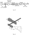
Fig. 11 is a schematic diagram illustrating the principle of a normal temperature direct detector. -
Fig. 12 is a schematic diagram illustrating structural modules of a normal temperature direct detector. -
Fig. 13 is a schematic diagram illustrating the principle of a normal temperature heterodyne mixing demodulation detector. -
Fig. 14 is a schematic diagram illustrating structural modules of a normal temperature heterodyne mixing detector. -
Fig. 15 is a diagram illustrating a detector array mounted in an arc. -
Fig. 16 is a diagram illustrating a detector array mounted in an arc that is composed of polylines. -
FIG. 17 is a schematic diagram illustrating a distribution of grid bars of a grid-type reflecting plate according to the present disclosure. -
Figs. 18 (a) and (b) illustrate the relationship among reflectivity, an angle of incidence and frequency with vertical polarization and horizontal polarization in a case of a=lam/4, b=a/5, and lam=100GHz. -
Fig. 19 is a schematic structural diagram of a grid-type reflecting plate according to an exemplary embodiment of the present disclosure. -
Fig. 20 is a schematic structural diagram of a grid-type reflecting plate according to another exemplary embodiment of the present disclosure. -
Fig. 21 is a schematic structural diagram of a grid-type reflecting plate according to another exemplary embodiment of the present disclosure. -
Fig. 22 is a schematic structural diagram of a grid-type reflecting plate according to another exemplary embodiment of the present disclosure. -
Fig. 23 is a schematic structural diagram of a passive security checking device according to another exemplary embodiment of the present disclosure. - Although the present disclosure will be fully described by referring to the drawings including preferred embodiments of the present disclosure, it should be understood that those skilled in the art can modify the invention described herein as well as obtaining the technical effect of the present disclosure. Therefore, it should be understood that the above description is a broad disclosure for those skilled in the art, and its content is not intended to limit the exemplary embodiments described in the present disclosure.
- In addition, in the following detailed description, for the convenience of explanation, many specific details are set forth to provide a comprehensive understanding of the embodiments of the present disclosure. However, obviously, one or more embodiments can also be implemented without these specific details. In other cases, well-known structures and devices are illustrated to simplify the drawings.
- According to the general inventive concept of the present disclosure, a receiving antenna unit for a passive security checking device is provided, wherein the receiving antenna unit includes at least one horn antenna including a horn body and a waveguide connected to the horn body, and a ratio of a long side to a short side of a horn opening of the horn body is greater than 1.2.
- According to another general inventive concept of the present disclosure, a passive security checking device is provided, wherein the passive security checking device includes: an optical means for reflecting and converging millimeter wave/terahertz waves radiated by an object under check and millimeter wave/terahertz waves reflected by background environment; and a detector array for receiving converged millimeter waves/terahertz waves and converting the received millimeter waves/terahertz waves into electrical signals, the detector array including the above receiving antenna unit.
-
Fig. 1 is a schematic structural diagram of a passive security checking device according to an exemplary embodiment of the present disclosure. - As shown in
Fig. 1 , the passive security checking device according to the present disclosure includes a reflectingplate 2 and a servo system thereof, alens 3, adetector array 4, a data collecting and processing means 6, adisplay 7 and adistribution box 5. Terahertz waves (or millimeter waves) spontaneously radiated by the object under check and terahertz waves (or millimeter waves) reflected by the background environment are incident on the reflectingplate 2 through awindow 1 on a housing, and are reflected to thelens 3 by thereflecting plate 2, then received by thedetector array 4 through the convergence of thelens 3. Thedetector array 4 converts the received Terahertz waves (or millimeter waves) into electrical signals. The data collecting and processing means 6 is connected to thedetector array 4 to receive the electrical signals from thedetector array 4 and generate a millimeter wave/terahertz wave image. Thedisplay 7 is connected to the data collecting and processing means 6, to receive and display the millimeter wave/terahertz wave image generated by the data collecting and processing means 6. Thedistribution box 5 is configured to supply power to the whole passive security checking device. -
Fig. 2 is a diagram illustrating an operation principle of a passive security checking device according to an exemplary embodiment of the present disclosure.Fig. 3 is an operation flowchart of a passive security checking device according to an exemplary embodiment of the present disclosure. - As shown in
Figs. 2 and3 , the servo system of the reflectingplate 2 controls the reflectingplate 2 to reciprocate, and the reciprocal of a period T of the movement is the imaging frame rate s. When the reflectingplate 2 swings from the maximum elevation angle to the minimum elevation angle, the swing angle is equal to θ, to complete scanning at the angle of field that is equal to 2θ in a height direction within a range of the depth of field. The reflectingplate 2 forms an image from the maximum elevation angle to the minimum elevation angle. The data collecting and processing means 6 has been collecting data in this process. The control system of the reflectingplate 2, for example, may be equipped with a position encoder to feed back scanning positions of the reflecting plate with high precision. When collecting data, the data collecting and processing means 6 first marks the collected data according to the information of the position encoder for distinguishing the data of the next image, then the data collecting and processing means 6 performs digital filtering and image reconstruction to the collected data to generate a millimeter wave image. Then, after performing image denoising and enhancement to the image, the data collecting and processing means 6 transfers the image data to thedisplay 7, so that the image may be displayed, suspicious objects may be labeled and automatic alarm may be performed on thedisplay 7. - In an exemplary embodiment, as shown in
Figs. 4 and 5 , the receiving antenna unit for the passive security checking device includes a plurality ofhorn antennae 410, wherein thehorn antenna 410 includes ahorn body 411 and awaveguide 412 connected to thehorn body 411. A ratio of the long side to the short side of a horn opening of thehorn body 411 is greater than 1.2. The plurality ofhorn antennas 410 are one-dimensionally arranged or arranged in an arc in a direction of the short side of the horn opening of thehorn body 411, that is, short sides of the plurality of horn openings may be arranged into two parallel straight lines or two parallel curves. - In an exemplary embodiment, as shown in
Figs. 4 and 5 , thewaveguide 412 is a rectangular waveguide. It should be noted that those skilled in the art should understand that in some other embodiments of the present disclosure, thewaveguide 412 may also have other shapes, such as circle. - In an exemplary embodiment, as shown in
Fig. 4 , the long side a1 of the horn opening of thehorn antenna 410 corresponds to the long side a of the rectangular waveguide. In such a case, the ratio of the long side a1 to the short side b1 of the horn opening of thehorn antenna 410 is greater than 1.2, preferably ≥1.5. The size of the long side a1 depends on the resolution required by the system with ensuring the radiation performance of the horn antenna, and the short side b1 depends on the radiometer interval satisfying Rayleigh sampling, generally a1>a, b1>b; wherein a and b are the long side and the short side of therectangular waveguide 412, respectively. However, the ratio of the long side a1 to the short side b1 of thehorn antenna 410 should not be too large, otherwise, the resolution will be sacrificed. Typically, a1/b1≤5. In addition, in order that the horn antenna has characteristics such as high radiation efficiency, high gain, positive-direction radiation and low sidelobe, etc., the height H of the horn body of the horn antenna 400 typically meets H ≥a1, preferably H is in the range of 1.2a1 to 1.5a1, or 1.5a1 to 2a1, or 2a1 to 3a1, for example, H is equal to 1.5a1, 2a1, and so on. - In an exemplary embodiment, as shown in
Fig. 5 , the short side b2 of the horn opening of thehorn antenna 410 corresponds to the long side a of the rectangular waveguide. In such a case, the ratio of the long side a2 to the short side b2 of the horn opening of thehorn antenna 410 is greater than 1.2, preferably ≥1.5. The size of the long side a2 depends on the resolution required by the system with ensuring the radiation performance of thehorn antenna 410, and the short side b2 depends on the radiometer interval satisfying Rayleigh sampling, generally a2>b, b2>a; wherein a and b are the long side and the short side of therectangular waveguide 412, respectively. However, the ratio of the long side a2 to the short side b2 of thehorn antenna 410 should not be too large, otherwise, the resolution will be sacrificed. Typically, a2/b2≤5. In addition, in order that the horn antenna has characteristics such as high radiation efficiency, high gain, positive-direction radiation and low sidelobe, etc., the height H of the horn body of the horn antenna 400 typically meets H ≥a2, preferably H is in the range of 1.2a2 to 1.5a2, or 1.5a2 to 2a2, or 2a2 to 3a2, for example, H is equal to 1.5a2, 2a2, and so on. - When less than 300GHz, the brightness Bf of the spontaneous radiation spectrum of the human body may be calculated according to the following formula:

- wherein k is Boltzmann constant and its value is 1.38×10⁻²³J•K-1;
- T is the absolute temperature of the object, the unit is K;
- c is the speed of light, and its value is 3 × 10⁸m•s-1;
- Since thermal radiation noise signals of the human body and the suspicious object are non-polarized, and the receiving antenna is linearly polarized, the receiving antenna may only detect half of the total power of the thermal radiation signals incident on the antenna surface without considering other losses,

- wherein, Ar is the equivalent area of the receiving antenna,
- f(θ, ϕ) is the directional diagram of the receiving antenna.
- On one hand, since the absolute temperature of the human body is normally 310K, the brightness of the spontaneous radiation spectrum is constant. The gain of the receiving antenna may be represented as G=Ar ∗max(f(θ,ϕ)) Therefore, it is quite effective to increase the power P received by the detector by increasing the gain of the receiving antenna. For the horn antenna, its gain increases as its size does. As the size of the horn antenna increases, the sampling rate of the antenna array of the same length decreases. On the other hand, the coupling efficiency of the horn antenna with the lens decreases as the wave beam angle increases (
Fig. 6 is a diagram illustrating the coupling process of the horn antenna with the lens.Fig. 7 is a diagram illustrating the coupling efficiency of the horn antenna with the lens). Therefore, the power coupling efficiency of the horn antenna with the optical system and the sampling interval are contradictory with each other. In order to solve the contradiction between the coupling efficiency of the optical system and the sampling interval to improve the signal-to-noise ratio of imaging, it is necessary to increase the gain of the horn antenna, that is, to arrange as many antennae as possible in a certain area while increasing its aperture, which relates to designs of antenna size and arrangement. - The receiving antenna unit provided by the present disclosure adopts a bar-shaped
horn antenna 410, so that the beam width in the direction of its long side may be effectively compressed, its 3dB beam angle is small, and it has a higher coupling efficiency when applied in combination with a lens. In the direction of its short side, adequate antennas with the advantage of short size may be arranged, so that the sampling rate requirements may be satisfied. That is, the horn antenna reduces the overflow energy as much as possible in one dimension under the condition that it meets the sampling rate requirements in another dimension such that a better compromise effect can be obtained. Moreover, the hardware cost of the system can be greatly reduced by using one-row detector arrangement. - In an exemplary embodiment, the detector array is arranged in the direction of the short side to achieve Rayleigh sampling, i.e., only one sampling is performed within one 3dB wave beam width, so that the coupling efficiency of the receiving antenna with the lens achieves nearly 50% in the direction of the short side and over 90% in the direction of the long side, thereby improving the overall coupling efficiency, the signal-to-noise ratio of the system and the imaging quality.
-
Fig. 8 is a directional diagram of a W-waveband horizontally polarized bar-shaped horn antenna of 6x18x30mm.Fig. 9 is a diagram illustrating the distribution of spots on the focal plane of the horn antenna according to the present disclosure after passing through the lens. It can be seen fromFig. 9 that the spots are distributed in an ellipse, and has a larger size in the direction of scanning. - Table 1 shows the coupling efficiencies of a normal horn antenna and the bar-shaped horn antenna of the present disclosure with the same lens at the same passage spacing.
Table 1 Antenna size 6X4.9X15mm 6X18X30mm Type of horn antenna Normal horn antenna Horn antenna of the present disclosure 3dB wave beam width Plane E 35.51° Plane E 28.02° Plane H 34.3° Plane H 18.78° gain 14.57dBi 18.16dBi Positive-feed coupling efficiency 50.2% 72.08% - It can be seen from Table 1 that for the bar-shaped horn antenna of the present disclosure, since its 3dB beam width is no longer symmetrical on planes E and H, the beam spot sizes in the horizontal and vertical directions of the object plane are different, which is no longer round, but oval. This oval beam spot is more advantageous than a circular beam spot for a scanning imaging system for human security checking. This is because the field of view in the height direction is realized by mechanical scanning. Thus, over-sampling can be realized by a high-speed ADC, thereby increasing the temperature sensitivity integration time of the detector. Further, in the direction of the detector array, only Rayleigh sampling can be achieved due to the limitation of the detector interval, causing the sampling of the imaged image to be asymmetric in the horizontal direction and in the height direction, which further causes different spatial resolutions. In this case, an elliptical beam spot is formed with the focusing of the polarization-enhanced bar-shaped horn antenna and being converged by the lens (as shown in
Fig. 9 ), i.e., the beam spot is larger in the height direction and smaller in the horizontal direction. Then the entire field of view is sampled by scanning (as shown inFig. 10 ). The spot in this form may be used for compensating for asymmetry of the spatial resolution caused by oversampling in the height direction and Rayleigh sampling in the array direction. - In addition, only when the polarization mode of the receiving antenna is consistent with the polarization mode of the received electromagnetic wave, the receiving antenna may effectively receive the signal. Otherwise the quality of the received signal will be deteriorated, or even no signal may be received at all. This phenomenon is called polarization mismatch. When the detector uses a rectangular waveguide, its polarization direction is determined by the direction of the waveguide port. The short side of the waveguide port parallel to the ground is defined as horizontal polarization, and the long side parallel to the ground plane is defined as vertical polarization.
- The process of the thermal radiation detector from the human body or suspicious object can be divided into two steps: the first step is the process from the human body or suspicious object to the receiving antenna, and the second step is the transmission process of the detector content signal.
- In the first step, the thermal radiation of the human body or the suspicious object in the terahertz band penetrates the clothing, reaches the reflecting plate and is reflected to the lens, then penetrates the front and back surfaces of the lens, and is finally received by the receiving antenna at the front end of the detector.
- At an interface between free space and medium, reflection coefficients R // and R ⊥ of parallel polarized waves and vertically polarized waves may be represented as:


- In the formula, θi is the angle of incidence, n is the received refractivity.
- By solving the above formula, it can be found that R ⊥ is always greater than R //, that is, the transmissivity of the parallel polarization component is greater. Reflection occurs at four locations: clothing, the reflecting plate, the front and rear surfaces of the lens, resulting in that at the receiving antenna, the power of the horizontal polarization component should be greater than that of the vertical polarization component. In this case, a horizontally polarized antenna is selected as the antenna at the front end of the detector.
- In the second step, A) For the normal temperature direct detector, as shown in
Figs. 11 and 12 , inside the detector, signals received by the receiving antenna are transferred through a transition waveguide to a transition structure between the waveguide and the coplanar probe, and then passes through multi-stage low noise amplifier (LNA), and finally demodulated by a demodulator. In order to maximize the received horizontal polarization component, polarization matching at two positions is involved here: at first position, the polarization direction of the rectangular waveguide of the horn antenna needs to be matched as horizontal polarization, and the polarization directions of thewaveguide port surface 412A of therectangular waveguide 412 of thehorn antenna 410 and thewaveguide port surface 422A of thetransition waveguide section 422 need to match each other; at second position, the polarization direction from thetransition waveguide section 422 to thecoplanar line 421 also needs to match. If a polarization mismatch occurs at either or both of the two positions, the power transmission efficiency may be seriously affect, resulting in a low signal-to-noise ratio. - B) For the normal temperature heterodyne mixing-demodulation detector, as shown in
Figs. 13 and 14 , inside the detector, the signal received by the receiving antenna is transferred to themixer 426 throughRF input waveguide 423, and then passes through an intermediate frequency amplifier andfilter 427, finally demodulated by the demodulator. In order to maximize the received horizontal polarization component, polarization matching at two positions is involved here: at first position, the polarization direction of the waveguide of thehorn antenna 410 needs to be matched as horizontal polarization, and the polarization directions of thewaveguide port surface 412A of therectangular waveguide 412 of thehorn antenna 410 and thewaveguide port surface 423A of theRF input waveguide 423 need to match each other; at second position, the polarization direction of the localoscillator input waveguide 424 also needs to match. If a polarization mismatch occurs at either or both of the two positions, the power transmission efficiency may be seriously affect, resulting in a low signal-to-noise ratio. - In an exemplary embodiment, as shown in
Fig. 15 , thedetector array 4 includes adetector support 430 and a plurality ofdetectors 420 that are mounted on thedetector support 430 and arranged in an arc, and the radius of curvature of the arc is selected to be 0.8 to 1.2 times the image distance. Thedetector array 4 is placed on the focal plane of thelens 3. In some other embodiments of the present disclosure, as shown inFig. 16 , for the convenience of installation, the arrangement in an arc may be segmented into polylines. - According to another aspect of the present disclosure, a passive security checking device is further provided. The passive security checking device includes an optical means for reflecting and converging millimeter wave/terahertz waves spontaneously radiated by an object under check and millimeter wave/terahertz waves reflected by background environment; and a
detector array 4 for receiving converged millimeter waves/terahertz waves and converting the received millimeter waves/terahertz waves into electrical signals, thedetector array 4 including the above receiving antenna unit. - In an exemplary embodiment, as shown in
Figs. 19-22 , the optical means of the passive security checking device includes a grid-type reflecting plate 2 for reflecting terahertz waves (or millimeter waves) spontaneously radiated by the object under check and terahertz waves (or millimeter waves) reflected by the background environment, wherein the distribution of thegrids 202 on the grid-type reflecting plate 2 matches the polarization direction of the receiving antennae of the detectors in thedetector array 4. - The receiving antenna of the detector of the passive security checking device based on normal temperature detector is typically linearly polarized. The spontaneous radiation of the human body and the suspicious object is non-polarized. The linearly polarized receiving antenna can only detect the spontaneous radiation component that matches its polarization direction, while the reflexive radiation component orthogonal to its polarization direction cannot be detected but reflected by the receiving antenna. The reflected wave becomes the noise of the system and reduces the temperature sensitivity of the system, affecting the final image quality and identification of suspicious objects. Therefore, the passive security checking device of the present disclosure adopts the grid-
type reflecting plate 2, and the distribution of thegrids 202 on the grid-type reflecting plate 2 matches the polarization direction of the receiving antennae of thedetector array 4, so as to perform polarization selection to the reflectingplate 2, thereby improving the signal-to-noise ratio of the system, the temperature sensitivity of the system, and the image quality and identification of suspicious objects. In addition, the grid-type reflecting plate 2 may reduce the weight of the reflectingplate 2 and reduce the wind resistance of the swing of the reflectingplate 2, particularly in a case where the imaging speed is greater than 10 Hz. - In an exemplary embodiment, as shown in
Figs. 19-22 , the grid-type reflecting plate 2 includes asubstrate 201 and a plurality ofmetal grids 202 arranged on thesubstrate 201, wherein the plurality ofmetal grids 202 are periodically arranged in one dimension, for example, horizontally or vertically.Fig. 17 illustrates the arrangement of thegrids 202, wherein a is the spacing between themetal grids 202 and b is the width of themetal grid 202. Specifically, the sizes of a and b depend on a balance among desired reflectivity, wind resistance, and weight.Figs. 18 (a) and (b) illustrate the relationship among reflectivity, an angle of incidence and frequency with vertical polarization and horizontal polarization in a case of a=lam/4, b=a/5, and lam=100GHz. - In an exemplary embodiment, if the polarization direction of the receiving antenna is the arrangement direction of the detector array, the arrangement direction of the
metal grid 202 may also certainly be the arrangement direction of the detector array. In other words, the polarization direction of the antenna and the arrangement direction of themetal grid 202 both are the arrangement direction of the detector array. - In an exemplary embodiment, if the polarization direction of the receiving antenna is the orthogonal direction of the arrangement of the detector array, the arrangement direction of the
metal grid 202 may also certainly be the orthogonal direction of the arrangement of the detector array. In other words, the polarization direction of the antenna and the arrangement direction of themetal grid 202 both are the orthogonal direction of the arrangement of the detector array. - Table 2 summarizes the reflectivity of vertical polarization and horizontal polarization with different a, b parameters.
Table 2 Distance between grids a Grid width b R vertical polarization R parallel polarization Example 1 Lam/10 a/5 >0.97 <0.023 Example2 Lam/4 a/5 >0.84 <0.0085 Example3 Lam/5 a/5 >0.89 <0.007 Example4 Lam/5 a/3 >0.95 <0.002 Example5 Lam/5 a/2 >0.987 <0.1 Example6 Lam/3 a/2 >0.962 <0.19 - It can be seen from Table 2 that for the polarization direction to be selected, if the reflectivity is required to reach 95%, the spacing between any two
adjacent metal grids 202 should satisfy a≤1am/2, and the width of themetal grid 202 preferably satisfies b≦a/2. It should be noted that those skilled in the art should understand that other values may also be used in some other embodiments of the present disclosure. - As shown in
Figs. 19-22 , in some exemplary embodiments, the shape of the grid-type reflecting plate 2 includes, but is not limited to, a circle, an ellipse, a square, a rectangle, and a polygon. - In addition, it should be noted that those skilled in the art should understand that in some other embodiments of the present disclosure, the
lens 3 of the optical means may be a focusing reflecting plate, such as an ellipsoidal mirror, a Cassegrain reflector, etc. The focusing reflecting plate may also be a grid-type reflecting plate. -
Fig. 23 is a schematic structural diagram of a passive security checking device according to another exemplary embodiment of the present disclosure. As shown inFig. 23 , the optical means may also adopt a polyhedral mirror 2' instead of the reflectingplate 2. The polyhedron mirror 2' includes a plurality of reflecting plates for reflecting terahertz waves (or millimeter waves) spontaneously radiated by the object under check and terahertz waves (or millimeter waves) reflected by the background environment, at least one of the plurality of reflecting plates being a grid-type reflecting plate. - According to another aspect of the present disclosure, a passive security checking device is further provided. The device includes an optical means for reflecting and converging millimeter wave/terahertz waves spontaneously radiated by an object under check and millimeter wave/terahertz waves reflected by background environment; and a
detector array 4 for receiving converged millimeter waves/terahertz waves and converting the received millimeter waves/terahertz waves into electrical signals, thedetector array 4 including the above receiving antenna unit. - As shown in
Fig. 1 , in an exemplary embodiment of the present disclosure, the passive security checking device may further include a data collecting and processing means 6. The data collecting and processing means 6 is wirelessly connected or wired electrically connected to thedetector array 4 to receive the scanning data obtained by scanning the object to be checked from the detector array, and generate high-resolution terahertz wave (or millimeter wave) holographic image by an image reconstruction algorithm, and use automatic identification algorithm to automatically identify suspicious objects in terahertz wave (or millimeter wave) image. For example, the data collecting and processing means 6 may include a personal computer (PC), server, workstation, etc. According to some embodiments, the data collecting and processing means 6 may include a processor and a memory. The processor may be electrically connected to the detector array to receive and process the scanning data. The memory may be electrically connected to the processor and store instructions. The instructions are executed by the processor, to cause the processor to perform image reconstruction, or control the security checking device to scan and image the object to be checked. - The passive security checking device may further include a
display 7. The display is connected to the data collecting and processing means 6, for receiving and displaying the terahertz wave (or millimeter wave) holographic image from the data collecting and processing means 6. It should be noted that in an exemplary embodiment, acontrol device 7 may be integrated with the data collecting and processing means 6. - In an exemplary embodiment of the present disclosure, the passive security checking device is a human passive security instrument. However, it should be noted that those skilled in the art should understand that in some other embodiments of the present disclosure, the present disclosure may also be used for detection of other detected objects such as packages.
- According to the above embodiments of the present disclosure, the passive security checking device and the receiving antenna unit thereof can improve the efficiency of the power coupling of the horn antenna with the lens on one hand; and on the other hand, can ensure the Rayleigh sampling interval of the detector. The passive security checking device and the receiving antenna unit thereof can solve the problem, faced by normal horn antennae, of contradiction between sampling interval and coupling efficiency. By controlling the polarization direction of the receiving antenna of the detector and increasing the gain of the receiving antenna, the signal-to-noise ratio of the system is increased. In addition, since the entire security checking system has various noises, such as the detector itself, environmental noise, background noise, and noise caused by clothing, the noise orthogonal to the polarization direction of the receiving antenna can be well suppressed, thereby improving the signal-to-noise ratio of the system.
Claims (14)
- A receiving antenna unit for a passive security checking device, wherein the receiving antenna unit comprises at least one horn antenna (410) comprising a horn body (411) and a waveguide (412) connected to the horn body, and a ratio of a long side to a short side of an horn opening of the horn body is greater than 1.2.
- The receiving antenna unit according to claim 1, wherein a plurality of horn antennae are one-dimensionally arranged or arranged in an arc in a direction of the short side of the horn opening of the horn body.
- The receiving antenna unit according to claim 2, wherein the waveguide is a rectangular waveguide.
- The receiving antenna unit according to claim 3, wherein the ratio of the long side to the short side of the horn opening of the horn body is not less than 1.5.
- The receiving antenna unit according to claim 4, wherein the ratio of the long side to the short side of the horn opening of the horn body is not more than 5.
- The receiving antenna unit according to claim 5, wherein a height of the horn body is H that is not less than a length of the long side of the horn opening of the horn body.
- The receiving antenna unit according to any one of claims 1-6, wherein the long side of the horn opening of the horn body corresponds to a long side of the waveguide.
- The receiving antenna unit according to any one of claims 1-6, wherein the short side of the horn opening of the horn body corresponds to a long side of the waveguide.
- A passive security checking device, wherein the passive security checking device comprises:an optical means for reflecting and converging millimeter wave/terahertz waves spontaneously radiated by an object under check and millimeter wave/terahertz waves reflected by background environment; anda detector array for receiving converged millimeter waves/terahertz waves and converting the received millimeter waves/terahertz waves into electrical signals, the detector array comprising the receiving antenna unit according to any one of claims 1-8.
- The passive security checking device according to claim 9, wherein a polarization direction of the horn antenna is horizontal polarization.
- The passive security checking device according to claim 10, wherein a detector in the detector array comprises a normal temperature direct detector comprising a coplanar line and a transition waveguide for inputting millimeter waves/terahertz waves, the polarization direction of the waveguide of the horn antenna being configured to be horizontal polarization, the polarization direction of a waveguide port surface of the waveguide of the horn antenna matching the polarization direction of a waveguide port surface of the transition waveguide; and/or
a polarization direction from the transition waveguide to the coplanar line matches the polarization direction of the waveguide of the horn antenna. - The passive security checking device according to claim 10, wherein a detector in the detector array comprises a normal temperature heterodyne mixing demodulation detector comprising a local oscillator input waveguide and a radio frequency input waveguide, a polarization direction of the waveguide of the horn antenna being configured to be horizontal polarization, a polarization direction of a waveguide port surface of the waveguide of the horn antenna matching a polarization direction of a waveguide port surface of the radio frequency input waveguide; and/or
a polarization direction of the local oscillator input waveguide matches the polarization direction of the waveguide of the horn antenna. - The passive security checking device according to any one of claims 9-12, further comprising:a data collecting and processing means that is connected to the detector array to receive electrical signals from the detector array and generate a millimeter wave/terahertz wave image; anda display that is connected to the data collecting and processing means, for receiving and displaying the generated millimeter wave/terahertz wave image from the data collecting and processing means.
- The passive security checking device according to any one of claims 9-12, wherein the passive security checking device is a human passive security instrument.
Applications Claiming Priority (1)
| Application Number | Priority Date | Filing Date | Title |
|---|---|---|---|
| CN201911402451.7A CN113126173B (en) | 2019-12-30 | 2019-12-30 | Passive security inspection equipment and receiving antenna unit thereof |
Publications (2)
| Publication Number | Publication Date |
|---|---|
| EP3845930A1 true EP3845930A1 (en) | 2021-07-07 |
| EP3845930B1 EP3845930B1 (en) | 2024-07-31 |
Family
ID=73856461
Family Applications (1)
| Application Number | Title | Priority Date | Filing Date |
|---|---|---|---|
| EP20216169.1A Active EP3845930B1 (en) | 2019-12-30 | 2020-12-21 | Passive security checking device and receiving antenna unit thereof |
Country Status (3)
| Country | Link |
|---|---|
| EP (1) | EP3845930B1 (en) |
| CN (1) | CN113126173B (en) |
| BR (1) | BR102020026731A2 (en) |
Families Citing this family (1)
| Publication number | Priority date | Publication date | Assignee | Title |
|---|---|---|---|---|
| CN116780209B (en) * | 2023-07-18 | 2024-02-27 | 中国人民解放军军事科学院系统工程研究院 | Integrated receiving and transmitting antenna applicable to millimeter wave products |
Citations (5)
| Publication number | Priority date | Publication date | Assignee | Title |
|---|---|---|---|---|
| US7583074B1 (en) * | 2005-12-16 | 2009-09-01 | Hrl Laboratories, Llc | Low cost millimeter wave imager |
| CN106918843A (en) * | 2017-01-23 | 2017-07-04 | 北京航天易联科技发展有限公司 | A kind of video speed scanning system based on passive type terahertz imaging |
| CN109361074A (en) * | 2018-11-12 | 2019-02-19 | 北京航空航天大学 | A Pyramid Horn Element Antenna for Suppressing Array Grating Lobes |
| CN109471194A (en) * | 2018-12-29 | 2019-03-15 | 同方威视技术股份有限公司 | Millimeter wave terahertz imaging equipment and object recognition and classification method |
| US20190115666A1 (en) * | 2016-03-14 | 2019-04-18 | Pioneer Corporation | Horn antenna array |
Family Cites Families (14)
| Publication number | Priority date | Publication date | Assignee | Title |
|---|---|---|---|---|
| JP4029217B2 (en) * | 2005-01-20 | 2008-01-09 | 株式会社村田製作所 | Waveguide horn array antenna and radar apparatus |
| DE602006020785D1 (en) * | 2006-05-23 | 2011-04-28 | Intel Corp | MILLIMETER WAVE COMMUNICATION SYSTEM FOR THE INTERIOR |
| CN101345344B (en) * | 2007-07-13 | 2012-09-05 | 上海磁浮交通工程技术研究中心 | Base station millimeter wave communication antenna integrating figuration and changed polarization |
| US8248321B2 (en) * | 2009-09-01 | 2012-08-21 | Raytheon Company | Broadband/multi-band horn antenna with compact integrated feed |
| CN102128841B (en) * | 2010-01-13 | 2015-04-08 | 东南大学 | Detecting device of terahertz imaging system |
| CN202373697U (en) * | 2011-10-30 | 2012-08-08 | 北京无线电计量测试研究所 | Ultra-wide-band pyramidal horn antenna array used for millimeter wave imaging security check system |
| CN202395161U (en) * | 2011-12-26 | 2012-08-22 | 上海磁浮交通发展有限公司 | High power beamforming vehicle-mounted antenna with two-stage structure |
| CN104466429A (en) * | 2013-11-08 | 2015-03-25 | 北京东方安高微电子科技有限公司 | Millimeter wave one-dimensional single-pulse biplane reflecting antenna |
| US9991607B1 (en) * | 2015-06-04 | 2018-06-05 | Rockwell Collins, Inc. | Circular array of ridged waveguide horns |
| US9666949B2 (en) * | 2015-09-09 | 2017-05-30 | Viasat, Inc. | Partially dielectric loaded antenna elements for dual-polarized antenna |
| JP6482456B2 (en) * | 2015-12-28 | 2019-03-13 | 日立オートモティブシステムズ株式会社 | Millimeter wave antenna and millimeter wave sensor using the same |
| CN109149116B (en) * | 2018-08-23 | 2020-06-09 | 西安空间无线电技术研究所 | Novel dual-polarized horn antenna |
| CN209150303U (en) * | 2018-12-26 | 2019-07-23 | 南京肯微弗通信技术有限公司 | Low section is inverted parabolic reflector antenna |
| CN109444975B (en) * | 2018-12-29 | 2024-06-11 | 清华大学 | Millimeter wave/terahertz wave imaging equipment |
-
2019
- 2019-12-30 CN CN201911402451.7A patent/CN113126173B/en active Active
-
2020
- 2020-12-21 EP EP20216169.1A patent/EP3845930B1/en active Active
- 2020-12-28 BR BR102020026731-0A patent/BR102020026731A2/en unknown
Patent Citations (5)
| Publication number | Priority date | Publication date | Assignee | Title |
|---|---|---|---|---|
| US7583074B1 (en) * | 2005-12-16 | 2009-09-01 | Hrl Laboratories, Llc | Low cost millimeter wave imager |
| US20190115666A1 (en) * | 2016-03-14 | 2019-04-18 | Pioneer Corporation | Horn antenna array |
| CN106918843A (en) * | 2017-01-23 | 2017-07-04 | 北京航天易联科技发展有限公司 | A kind of video speed scanning system based on passive type terahertz imaging |
| CN109361074A (en) * | 2018-11-12 | 2019-02-19 | 北京航空航天大学 | A Pyramid Horn Element Antenna for Suppressing Array Grating Lobes |
| CN109471194A (en) * | 2018-12-29 | 2019-03-15 | 同方威视技术股份有限公司 | Millimeter wave terahertz imaging equipment and object recognition and classification method |
Also Published As
| Publication number | Publication date |
|---|---|
| EP3845930B1 (en) | 2024-07-31 |
| BR102020026731A2 (en) | 2021-07-06 |
| CN113126173A (en) | 2021-07-16 |
| CN113126173B (en) | 2022-06-03 |
Similar Documents
| Publication | Publication Date | Title |
|---|---|---|
| AU2003245108B2 (en) | Real-time, cross-correlating millimetre-wave imaging system | |
| JP4362677B2 (en) | Circular direction detection antenna | |
| EP3550287A1 (en) | Image acquisition device, image acquisition method using same, and irradiation device | |
| CN109471195B (en) | Millimeter wave terahertz imaging equipment and object recognition and classification methods | |
| Zatta et al. | Broadband lens-integrated CMOS camera-type THz compact antenna test range | |
| EP3845930B1 (en) | Passive security checking device and receiving antenna unit thereof | |
| CN113126174B (en) | Passive security inspection equipment and optical device thereof | |
| Richter et al. | A multi-channel radiometer with focal plane array antenna for W-band passive millimeterwave imaging | |
| Anderton et al. | Security scanning at 94GHz | |
| KR100834422B1 (en) | Probe | |
| JPH09304517A (en) | Millimeter wave imaging radar | |
| KR100240894B1 (en) | Quadratic Square PIA Antenna | |
| US7443560B2 (en) | Scanning imaging apparatus | |
| Wang et al. | A 60 GHz passive repeater array with quasi-endfire radiation based on metal groove unit-cells | |
| Padin et al. | A measurement of the coupling between close-packed shielded cassegrain antennas | |
| Mohsan et al. | Cassegrain Antenna Design, Fabrication, and Testing for Passive Millimeter Wave Imaging | |
| US10006993B1 (en) | Compact passive millimeter wave (PMMW) camera | |
| KR102753916B1 (en) | Antenna device and electronic device | |
| Wang et al. | A Compact Robust Feed Antenna for Passive Millimeter-Wave Imaging Using Gap Waveguide Technology | |
| Anderton et al. | Sampling passive millimetre-wave imagery | |
| Lu et al. | Nonlinear Distortion Correction for Single Pixel Conical Scanning Radiometric Imaging System at W-Band | |
| US8462067B2 (en) | Apparatus for an antenna system | |
| Chen et al. | Limitations of symmetry test method for antennas as specified in ANSI C63. 5-2006 standard | |
| JP2677691B2 (en) | Compound detector | |
| Lian et al. | A Wide-Angle Scanning Focal Plane Array Design Method for Millimeter-Wave Applications |
Legal Events
| Date | Code | Title | Description |
|---|---|---|---|
| STAA | Information on the status of an ep patent application or granted ep patent |
Free format text: STATUS: REQUEST FOR EXAMINATION WAS MADE |
|
| PUAI | Public reference made under article 153(3) epc to a published international application that has entered the european phase |
Free format text: ORIGINAL CODE: 0009012 |
|
| 17P | Request for examination filed |
Effective date: 20201221 |
|
| AK | Designated contracting states |
Kind code of ref document: A1 Designated state(s): AL AT BE BG CH CY CZ DE DK EE ES FI FR GB GR HR HU IE IS IT LI LT LU LV MC MK MT NL NO PL PT RO RS SE SI SK SM TR |
|
| RIC1 | Information provided on ipc code assigned before grant |
Ipc: H01Q 21/08 20060101ALI20240130BHEP Ipc: H01Q 21/00 20060101ALI20240130BHEP Ipc: H01Q 19/195 20060101ALI20240130BHEP Ipc: H01Q 19/10 20060101ALI20240130BHEP Ipc: H01Q 19/06 20060101ALI20240130BHEP Ipc: H01Q 13/02 20060101ALI20240130BHEP Ipc: G01V 8/00 20060101AFI20240130BHEP |
|
| GRAP | Despatch of communication of intention to grant a patent |
Free format text: ORIGINAL CODE: EPIDOSNIGR1 |
|
| STAA | Information on the status of an ep patent application or granted ep patent |
Free format text: STATUS: GRANT OF PATENT IS INTENDED |
|
| INTG | Intention to grant announced |
Effective date: 20240314 |
|
| GRAS | Grant fee paid |
Free format text: ORIGINAL CODE: EPIDOSNIGR3 |
|
| GRAA | (expected) grant |
Free format text: ORIGINAL CODE: 0009210 |
|
| STAA | Information on the status of an ep patent application or granted ep patent |
Free format text: STATUS: THE PATENT HAS BEEN GRANTED |
|
| AK | Designated contracting states |
Kind code of ref document: B1 Designated state(s): AL AT BE BG CH CY CZ DE DK EE ES FI FR GB GR HR HU IE IS IT LI LT LU LV MC MK MT NL NO PL PT RO RS SE SI SK SM TR |
|
| REG | Reference to a national code |
Ref country code: CH Ref legal event code: EP Ref country code: GB Ref legal event code: FG4D |
|
| REG | Reference to a national code |
Ref country code: DE Ref legal event code: R096 Ref document number: 602020034799 Country of ref document: DE |
|
| REG | Reference to a national code |
Ref country code: IE Ref legal event code: FG4D |
|
| REG | Reference to a national code |
Ref country code: LT Ref legal event code: MG9D |
|
| REG | Reference to a national code |
Ref country code: NL Ref legal event code: MP Effective date: 20240731 |
|
| PG25 | Lapsed in a contracting state [announced via postgrant information from national office to epo] |
Ref country code: PT Free format text: LAPSE BECAUSE OF FAILURE TO SUBMIT A TRANSLATION OF THE DESCRIPTION OR TO PAY THE FEE WITHIN THE PRESCRIBED TIME-LIMIT Effective date: 20241202 |
|
| REG | Reference to a national code |
Ref country code: AT Ref legal event code: MK05 Ref document number: 1708988 Country of ref document: AT Kind code of ref document: T Effective date: 20240731 |
|
| PG25 | Lapsed in a contracting state [announced via postgrant information from national office to epo] |
Ref country code: PT Free format text: LAPSE BECAUSE OF FAILURE TO SUBMIT A TRANSLATION OF THE DESCRIPTION OR TO PAY THE FEE WITHIN THE PRESCRIBED TIME-LIMIT Effective date: 20241202 |
|
| PG25 | Lapsed in a contracting state [announced via postgrant information from national office to epo] |
Ref country code: NO Free format text: LAPSE BECAUSE OF FAILURE TO SUBMIT A TRANSLATION OF THE DESCRIPTION OR TO PAY THE FEE WITHIN THE PRESCRIBED TIME-LIMIT Effective date: 20241031 |
|
| PG25 | Lapsed in a contracting state [announced via postgrant information from national office to epo] |
Ref country code: NL Free format text: LAPSE BECAUSE OF FAILURE TO SUBMIT A TRANSLATION OF THE DESCRIPTION OR TO PAY THE FEE WITHIN THE PRESCRIBED TIME-LIMIT Effective date: 20240731 Ref country code: GR Free format text: LAPSE BECAUSE OF FAILURE TO SUBMIT A TRANSLATION OF THE DESCRIPTION OR TO PAY THE FEE WITHIN THE PRESCRIBED TIME-LIMIT Effective date: 20241101 Ref country code: PL Free format text: LAPSE BECAUSE OF FAILURE TO SUBMIT A TRANSLATION OF THE DESCRIPTION OR TO PAY THE FEE WITHIN THE PRESCRIBED TIME-LIMIT Effective date: 20240731 Ref country code: FI Free format text: LAPSE BECAUSE OF FAILURE TO SUBMIT A TRANSLATION OF THE DESCRIPTION OR TO PAY THE FEE WITHIN THE PRESCRIBED TIME-LIMIT Effective date: 20240731 |
|
| PG25 | Lapsed in a contracting state [announced via postgrant information from national office to epo] |
Ref country code: BG Free format text: LAPSE BECAUSE OF FAILURE TO SUBMIT A TRANSLATION OF THE DESCRIPTION OR TO PAY THE FEE WITHIN THE PRESCRIBED TIME-LIMIT Effective date: 20240731 |
|
| PG25 | Lapsed in a contracting state [announced via postgrant information from national office to epo] |
Ref country code: LV Free format text: LAPSE BECAUSE OF FAILURE TO SUBMIT A TRANSLATION OF THE DESCRIPTION OR TO PAY THE FEE WITHIN THE PRESCRIBED TIME-LIMIT Effective date: 20240731 |
|
| PG25 | Lapsed in a contracting state [announced via postgrant information from national office to epo] |
Ref country code: IS Free format text: LAPSE BECAUSE OF FAILURE TO SUBMIT A TRANSLATION OF THE DESCRIPTION OR TO PAY THE FEE WITHIN THE PRESCRIBED TIME-LIMIT Effective date: 20241130 Ref country code: AT Free format text: LAPSE BECAUSE OF FAILURE TO SUBMIT A TRANSLATION OF THE DESCRIPTION OR TO PAY THE FEE WITHIN THE PRESCRIBED TIME-LIMIT Effective date: 20240731 |
|
| PG25 | Lapsed in a contracting state [announced via postgrant information from national office to epo] |
Ref country code: HR Free format text: LAPSE BECAUSE OF FAILURE TO SUBMIT A TRANSLATION OF THE DESCRIPTION OR TO PAY THE FEE WITHIN THE PRESCRIBED TIME-LIMIT Effective date: 20240731 |
|
| PG25 | Lapsed in a contracting state [announced via postgrant information from national office to epo] |
Ref country code: ES Free format text: LAPSE BECAUSE OF FAILURE TO SUBMIT A TRANSLATION OF THE DESCRIPTION OR TO PAY THE FEE WITHIN THE PRESCRIBED TIME-LIMIT Effective date: 20240731 Ref country code: RS Free format text: LAPSE BECAUSE OF FAILURE TO SUBMIT A TRANSLATION OF THE DESCRIPTION OR TO PAY THE FEE WITHIN THE PRESCRIBED TIME-LIMIT Effective date: 20241031 |
|
| PG25 | Lapsed in a contracting state [announced via postgrant information from national office to epo] |
Ref country code: RS Free format text: LAPSE BECAUSE OF FAILURE TO SUBMIT A TRANSLATION OF THE DESCRIPTION OR TO PAY THE FEE WITHIN THE PRESCRIBED TIME-LIMIT Effective date: 20241031 Ref country code: PL Free format text: LAPSE BECAUSE OF FAILURE TO SUBMIT A TRANSLATION OF THE DESCRIPTION OR TO PAY THE FEE WITHIN THE PRESCRIBED TIME-LIMIT Effective date: 20240731 Ref country code: NO Free format text: LAPSE BECAUSE OF FAILURE TO SUBMIT A TRANSLATION OF THE DESCRIPTION OR TO PAY THE FEE WITHIN THE PRESCRIBED TIME-LIMIT Effective date: 20241031 Ref country code: NL Free format text: LAPSE BECAUSE OF FAILURE TO SUBMIT A TRANSLATION OF THE DESCRIPTION OR TO PAY THE FEE WITHIN THE PRESCRIBED TIME-LIMIT Effective date: 20240731 Ref country code: LV Free format text: LAPSE BECAUSE OF FAILURE TO SUBMIT A TRANSLATION OF THE DESCRIPTION OR TO PAY THE FEE WITHIN THE PRESCRIBED TIME-LIMIT Effective date: 20240731 Ref country code: IS Free format text: LAPSE BECAUSE OF FAILURE TO SUBMIT A TRANSLATION OF THE DESCRIPTION OR TO PAY THE FEE WITHIN THE PRESCRIBED TIME-LIMIT Effective date: 20241130 Ref country code: HR Free format text: LAPSE BECAUSE OF FAILURE TO SUBMIT A TRANSLATION OF THE DESCRIPTION OR TO PAY THE FEE WITHIN THE PRESCRIBED TIME-LIMIT Effective date: 20240731 Ref country code: GR Free format text: LAPSE BECAUSE OF FAILURE TO SUBMIT A TRANSLATION OF THE DESCRIPTION OR TO PAY THE FEE WITHIN THE PRESCRIBED TIME-LIMIT Effective date: 20241101 Ref country code: FI Free format text: LAPSE BECAUSE OF FAILURE TO SUBMIT A TRANSLATION OF THE DESCRIPTION OR TO PAY THE FEE WITHIN THE PRESCRIBED TIME-LIMIT Effective date: 20240731 Ref country code: ES Free format text: LAPSE BECAUSE OF FAILURE TO SUBMIT A TRANSLATION OF THE DESCRIPTION OR TO PAY THE FEE WITHIN THE PRESCRIBED TIME-LIMIT Effective date: 20240731 Ref country code: BG Free format text: LAPSE BECAUSE OF FAILURE TO SUBMIT A TRANSLATION OF THE DESCRIPTION OR TO PAY THE FEE WITHIN THE PRESCRIBED TIME-LIMIT Effective date: 20240731 Ref country code: AT Free format text: LAPSE BECAUSE OF FAILURE TO SUBMIT A TRANSLATION OF THE DESCRIPTION OR TO PAY THE FEE WITHIN THE PRESCRIBED TIME-LIMIT Effective date: 20240731 |
|
| PG25 | Lapsed in a contracting state [announced via postgrant information from national office to epo] |
Ref country code: RO Free format text: LAPSE BECAUSE OF FAILURE TO SUBMIT A TRANSLATION OF THE DESCRIPTION OR TO PAY THE FEE WITHIN THE PRESCRIBED TIME-LIMIT Effective date: 20240731 Ref country code: DK Free format text: LAPSE BECAUSE OF FAILURE TO SUBMIT A TRANSLATION OF THE DESCRIPTION OR TO PAY THE FEE WITHIN THE PRESCRIBED TIME-LIMIT Effective date: 20240731 Ref country code: SM Free format text: LAPSE BECAUSE OF FAILURE TO SUBMIT A TRANSLATION OF THE DESCRIPTION OR TO PAY THE FEE WITHIN THE PRESCRIBED TIME-LIMIT Effective date: 20240731 |
|
| PG25 | Lapsed in a contracting state [announced via postgrant information from national office to epo] |
Ref country code: EE Free format text: LAPSE BECAUSE OF FAILURE TO SUBMIT A TRANSLATION OF THE DESCRIPTION OR TO PAY THE FEE WITHIN THE PRESCRIBED TIME-LIMIT Effective date: 20240731 |
|
| PG25 | Lapsed in a contracting state [announced via postgrant information from national office to epo] |
Ref country code: CZ Free format text: LAPSE BECAUSE OF FAILURE TO SUBMIT A TRANSLATION OF THE DESCRIPTION OR TO PAY THE FEE WITHIN THE PRESCRIBED TIME-LIMIT Effective date: 20240731 |
|
| PG25 | Lapsed in a contracting state [announced via postgrant information from national office to epo] |
Ref country code: SK Free format text: LAPSE BECAUSE OF FAILURE TO SUBMIT A TRANSLATION OF THE DESCRIPTION OR TO PAY THE FEE WITHIN THE PRESCRIBED TIME-LIMIT Effective date: 20240731 Ref country code: IT Free format text: LAPSE BECAUSE OF FAILURE TO SUBMIT A TRANSLATION OF THE DESCRIPTION OR TO PAY THE FEE WITHIN THE PRESCRIBED TIME-LIMIT Effective date: 20240731 |
|
| REG | Reference to a national code |
Ref country code: DE Ref legal event code: R097 Ref document number: 602020034799 Country of ref document: DE |
|
| PLBE | No opposition filed within time limit |
Free format text: ORIGINAL CODE: 0009261 |
|
| STAA | Information on the status of an ep patent application or granted ep patent |
Free format text: STATUS: NO OPPOSITION FILED WITHIN TIME LIMIT |
|
| REG | Reference to a national code |
Ref country code: DE Ref legal event code: R119 Ref document number: 602020034799 Country of ref document: DE |
|
| PG25 | Lapsed in a contracting state [announced via postgrant information from national office to epo] |
Ref country code: MC Free format text: LAPSE BECAUSE OF FAILURE TO SUBMIT A TRANSLATION OF THE DESCRIPTION OR TO PAY THE FEE WITHIN THE PRESCRIBED TIME-LIMIT Effective date: 20240731 |
|
| 26N | No opposition filed |
Effective date: 20250501 |
|
| REG | Reference to a national code |
Ref country code: CH Ref legal event code: PL |
|
| PG25 | Lapsed in a contracting state [announced via postgrant information from national office to epo] |
Ref country code: LU Free format text: LAPSE BECAUSE OF NON-PAYMENT OF DUE FEES Effective date: 20241221 |
|
| PG25 | Lapsed in a contracting state [announced via postgrant information from national office to epo] |
Ref country code: SE Free format text: LAPSE BECAUSE OF FAILURE TO SUBMIT A TRANSLATION OF THE DESCRIPTION OR TO PAY THE FEE WITHIN THE PRESCRIBED TIME-LIMIT Effective date: 20240731 |
|
| REG | Reference to a national code |
Ref country code: BE Ref legal event code: MM Effective date: 20241231 |
|
| PG25 | Lapsed in a contracting state [announced via postgrant information from national office to epo] |
Ref country code: DE Free format text: LAPSE BECAUSE OF NON-PAYMENT OF DUE FEES Effective date: 20250701 |
|
| PG25 | Lapsed in a contracting state [announced via postgrant information from national office to epo] |
Ref country code: BE Free format text: LAPSE BECAUSE OF NON-PAYMENT OF DUE FEES Effective date: 20241231 |
|
| PG25 | Lapsed in a contracting state [announced via postgrant information from national office to epo] |
Ref country code: FR Free format text: LAPSE BECAUSE OF NON-PAYMENT OF DUE FEES Effective date: 20241231 |
|
| PG25 | Lapsed in a contracting state [announced via postgrant information from national office to epo] |
Ref country code: CH Free format text: LAPSE BECAUSE OF NON-PAYMENT OF DUE FEES Effective date: 20241231 |
|
| PG25 | Lapsed in a contracting state [announced via postgrant information from national office to epo] |
Ref country code: IE Free format text: LAPSE BECAUSE OF NON-PAYMENT OF DUE FEES Effective date: 20241221 |
|
| PGFP | Annual fee paid to national office [announced via postgrant information from national office to epo] |
Ref country code: GB Payment date: 20251111 Year of fee payment: 6 |
|
| PG25 | Lapsed in a contracting state [announced via postgrant information from national office to epo] |
Ref country code: CY Free format text: LAPSE BECAUSE OF FAILURE TO SUBMIT A TRANSLATION OF THE DESCRIPTION OR TO PAY THE FEE WITHIN THE PRESCRIBED TIME-LIMIT Effective date: 20240731 |