EP3845882A1 - Analysis device, analysis method, trace liquid collection device, and trace liquid collection method - Google Patents
Analysis device, analysis method, trace liquid collection device, and trace liquid collection method Download PDFInfo
- Publication number
- EP3845882A1 EP3845882A1 EP19855012.1A EP19855012A EP3845882A1 EP 3845882 A1 EP3845882 A1 EP 3845882A1 EP 19855012 A EP19855012 A EP 19855012A EP 3845882 A1 EP3845882 A1 EP 3845882A1
- Authority
- EP
- European Patent Office
- Prior art keywords
- flow channel
- liquid sample
- liquid
- sample
- recited
- Prior art date
- Legal status (The legal status is an assumption and is not a legal conclusion. Google has not performed a legal analysis and makes no representation as to the accuracy of the status listed.)
- Pending
Links
Images


Classifications
-
- G—PHYSICS
- G01—MEASURING; TESTING
- G01N—INVESTIGATING OR ANALYSING MATERIALS BY DETERMINING THEIR CHEMICAL OR PHYSICAL PROPERTIES
- G01N21/00—Investigating or analysing materials by the use of optical means, i.e. using sub-millimetre waves, infrared, visible or ultraviolet light
- G01N21/01—Arrangements or apparatus for facilitating the optical investigation
- G01N21/11—Filling or emptying of cuvettes
-
- G—PHYSICS
- G01—MEASURING; TESTING
- G01N—INVESTIGATING OR ANALYSING MATERIALS BY DETERMINING THEIR CHEMICAL OR PHYSICAL PROPERTIES
- G01N21/00—Investigating or analysing materials by the use of optical means, i.e. using sub-millimetre waves, infrared, visible or ultraviolet light
- G01N21/62—Systems in which the material investigated is excited whereby it emits light or causes a change in wavelength of the incident light
- G01N21/63—Systems in which the material investigated is excited whereby it emits light or causes a change in wavelength of the incident light optically excited
- G01N21/64—Fluorescence; Phosphorescence
- G01N21/645—Specially adapted constructive features of fluorimeters
-
- G—PHYSICS
- G01—MEASURING; TESTING
- G01N—INVESTIGATING OR ANALYSING MATERIALS BY DETERMINING THEIR CHEMICAL OR PHYSICAL PROPERTIES
- G01N21/00—Investigating or analysing materials by the use of optical means, i.e. using sub-millimetre waves, infrared, visible or ultraviolet light
- G01N21/62—Systems in which the material investigated is excited whereby it emits light or causes a change in wavelength of the incident light
- G01N21/63—Systems in which the material investigated is excited whereby it emits light or causes a change in wavelength of the incident light optically excited
- G01N21/64—Fluorescence; Phosphorescence
- G01N21/6428—Measuring fluorescence of fluorescent products of reactions or of fluorochrome labelled reactive substances, e.g. measuring quenching effects, using measuring "optrodes"
-
- G—PHYSICS
- G01—MEASURING; TESTING
- G01N—INVESTIGATING OR ANALYSING MATERIALS BY DETERMINING THEIR CHEMICAL OR PHYSICAL PROPERTIES
- G01N21/00—Investigating or analysing materials by the use of optical means, i.e. using sub-millimetre waves, infrared, visible or ultraviolet light
- G01N21/75—Systems in which material is subjected to a chemical reaction, the progress or the result of the reaction being investigated
- G01N21/76—Chemiluminescence; Bioluminescence
-
- G—PHYSICS
- G01—MEASURING; TESTING
- G01N—INVESTIGATING OR ANALYSING MATERIALS BY DETERMINING THEIR CHEMICAL OR PHYSICAL PROPERTIES
- G01N21/00—Investigating or analysing materials by the use of optical means, i.e. using sub-millimetre waves, infrared, visible or ultraviolet light
- G01N21/01—Arrangements or apparatus for facilitating the optical investigation
- G01N21/03—Cuvette constructions
- G01N2021/0346—Capillary cells; Microcells
-
- G—PHYSICS
- G01—MEASURING; TESTING
- G01N—INVESTIGATING OR ANALYSING MATERIALS BY DETERMINING THEIR CHEMICAL OR PHYSICAL PROPERTIES
- G01N21/00—Investigating or analysing materials by the use of optical means, i.e. using sub-millimetre waves, infrared, visible or ultraviolet light
- G01N21/62—Systems in which the material investigated is excited whereby it emits light or causes a change in wavelength of the incident light
- G01N21/63—Systems in which the material investigated is excited whereby it emits light or causes a change in wavelength of the incident light optically excited
- G01N21/64—Fluorescence; Phosphorescence
- G01N21/6428—Measuring fluorescence of fluorescent products of reactions or of fluorochrome labelled reactive substances, e.g. measuring quenching effects, using measuring "optrodes"
- G01N2021/6439—Measuring fluorescence of fluorescent products of reactions or of fluorochrome labelled reactive substances, e.g. measuring quenching effects, using measuring "optrodes" with indicators, stains, dyes, tags, labels, marks
-
- G—PHYSICS
- G01—MEASURING; TESTING
- G01N—INVESTIGATING OR ANALYSING MATERIALS BY DETERMINING THEIR CHEMICAL OR PHYSICAL PROPERTIES
- G01N21/00—Investigating or analysing materials by the use of optical means, i.e. using sub-millimetre waves, infrared, visible or ultraviolet light
- G01N21/62—Systems in which the material investigated is excited whereby it emits light or causes a change in wavelength of the incident light
- G01N21/63—Systems in which the material investigated is excited whereby it emits light or causes a change in wavelength of the incident light optically excited
- G01N21/64—Fluorescence; Phosphorescence
- G01N21/645—Specially adapted constructive features of fluorimeters
- G01N2021/6482—Sample cells, cuvettes
-
- G—PHYSICS
- G01—MEASURING; TESTING
- G01N—INVESTIGATING OR ANALYSING MATERIALS BY DETERMINING THEIR CHEMICAL OR PHYSICAL PROPERTIES
- G01N21/00—Investigating or analysing materials by the use of optical means, i.e. using sub-millimetre waves, infrared, visible or ultraviolet light
- G01N21/01—Arrangements or apparatus for facilitating the optical investigation
- G01N21/03—Cuvette constructions
- G01N21/05—Flow-through cuvettes
Definitions
- the present disclosure relates to an analysis device, an analysis method, a trace liquid collection device, and a trace liquid collection method.
- Patent Document 1 Japanese Patent No. 4645739
- Patent Document 2 Japanese Patent No. 4853518
- Patent Document 1 and Patent Document 2 since it is configured such that a liquid sample is dropped onto a sample table, in cases where a trace amount of a liquid sample to be analyzed is as extremely small as about 1 nL to 100 nL, it is difficult to control the dropping. On the other hand, in cases where the liquid sample is diluted to ensure an appropriate amount for dripping, the concentration of the liquid sample becomes too low. Thus, it was difficult to analyze a trace amount of a liquid sample below 1 ⁇ L.
- the present disclosure has been made in view of the above problems, and it is an object of the present disclosure to provide an analysis device, an analysis method, a trace liquid collection device, and a trace liquid collection method capable of analyzing a trace amount of a liquid sample.
- An analysis device is provided with:
- the measurement unit is provided with an aperture member for limiting the light directed from the light irradiation unit toward the liquid sample, the aperture member having an opening width shorter than a liquid length of the liquid sample in the flow channel, the liquid sample being held in the flow channel.
- the analysis device may further include a liquid collection device configured to collect a trace amount of a fluid and a device main body configured to allow the liquid collection device to be inserted.
- the liquid collection device preferably includes a flow channel member in which the flow channel is formed and the suction mechanism.
- the device main body preferably includes the measurement unit therein. The measurement unit preferably measures the liquid sample held in the flow channel member inserted into an inside of the device main body.
- the suction mechanism preferably suctions the liquid sample so that the liquid sample is held between air layers or liquid layers formed on both end sides of the flow channel.
- the liquid sample may be a mixture in which a sample including a nucleic acid, an amino acid, a peptide, a protein, a lipid, a metabolite, a cell, a structural body constituting a part of a cell, a chromosome, a viral particle, and a bacterium, and a fluorescent reagent for fluorescently labeling the sample, a molecular reagent such as an antibody having a fluorescently labeled specific binding ability, or a luminescent reagent for luminescently labeling are mixed.
- the suction mechanism suctions two types of liquids of a sample including a nucleic acid, an amino acid, a peptide, a protein, a lipid, a metabolite, a cell and a fluorescent reagent for fluorescently labeling the sample or a luminescent reagent for luminescent labeling in this order, and mixes the two types of suctioned liquids in the flow channel.
- the measurement unit preferably measures a mixture in which the two types of liquids are mixed.
- the analysis device may include a liquid length measurement unit configured to measure a liquid length of the liquid sample held in the flow channel, the liquid length measurement means calculating a volume of the liquid sample.
- a suction amount of the liquid sample by the suction mechanism may be corrected based on a calculated volume of the liquid sample.
- a result of the measurement may be corrected based on a calculated volume of the liquid sample.
- the suction mechanism repeatedly pressurizes and depressurizes the inside of the flow channel while holding the sample and the fluorescent reagent or the luminescent reagent in the flow channel to mix the sample and the fluorescent reagent.
- a mixture can be prepared by controlling the suction mechanism.
- the device main body may be provided with a guide for guiding insertion of the flow channel member, the guide extending in an insertion direction of the flow channel member.
- the aperture member is preferably configured by the guide.
- the guide has a function to guide the insertion of the flow channel member, the number of components can be reduced.
- a suction amount of the liquid sample is 1 nL to 100 nL. According to the above-described configuration, it is possible to suitably analyze an extremely small amount of a liquid sample.
- a hollow cross-section of the flow channel may be circular. According to the above-described configuration, it is possible to stably hold the liquid sample in the flow channel
- an inner diameter of the flow channel may be 2.0 mm or less.
- An analysis method based on the present disclosure includes:
- the above-described analysis method it is possible to measure optical properties of a trace amount of a liquid sample using the measurement unit while holding the liquid sample suctioned into the flow channel by the suction mechanism in the flow channel. Furthermore, by limiting the light from the light irradiation unit toward the liquid sample by the aperture member having the opening width shorter than the liquid length of the liquid sample held in the flow channel, even in cases where the quantity of the suctioned liquid sample varies, it is possible to emit the light to the part where the liquid sample is present. This allows an analysis of a trace amount of a liquid sample.
- the liquid sample is preferably suctioned so that the liquid sample is held between air layers or liquid layers formed on both end sides of the flow channel.
- a suction amount of the liquid sample may be 1 nL to 100 nL. According to the above-described analysis method, an extremely small amount of the liquid sample can be suitably analyzed.
- the liquid sample may be a mixture in which a sample including a nucleic acid, an amino acid, a peptide, a protein, a lipid, a metabolite, a cell and a fluorescent reagent for fluorescently labeling the sample or a luminescent reagent for luminescently labeling the sample are mixed.
- a sample including a nucleic acid, an amino acid, a peptide, a protein, a lipid, a metabolite, a cell and a fluorescent reagent for fluorescently labeling the sample or a luminescent reagent for luminescently labeling the sample are mixed. According to the above-described analysis method, it is possible to collect and measure a mixture mixed in advance.
- the above-described analysis method may be configured such that two types of liquids of a sample including a nucleic acid, an amino acid, a peptide, a protein, a lipid, a metabolite, a cell and a fluorescent reagent for fluorescently labeling the sample or a luminescent reagent for luminescent labeling are suctioned by the above-described suction mechanism in this order, the two types of liquids suctioned in the flow channel are mixed, and a mixture in which the two types of liquids are mixed are measured. In this case, it is preferable to measure a mixture in which the above-described two types of liquids are mixed.
- the present disclosure may be configured such that a liquid length of the liquid sample held in the flow channel is measured and a volume of the liquid sample is calculated.
- a suction amount of the liquid sample may be corrected based on a calculated volume of the liquid sample.
- a result of the measurement may be corrected based on a calculated volume of the liquid sample.
- the sample and the fluorescent reagent may be mixed by repeatedly pressurizing and depressurizing the inside of the flow channel while holding the sample and the luminescent reagent or the luminescent reagent in the flow channel.
- a trace liquid collection device includes:
- an analysis device an analysis method, a trace liquid collection device, and a trace liquid collection method capable of performing an analysis of a trace amount of a liquid sample.
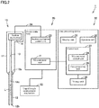
- FIG. 1 is a perspective view showing an external view of an analysis device according to Embodiment 1.
- FIG. 2 is a schematic configuration diagram showing the configuration of the analysis device according to Embodiment 1. Referring to FIG. 1 and FIG. 2 , an analysis device 1 according to Embodiment 1 will be described.
- the analysis device 1 is a device for analyzing a quantitative and/or a concentration, etc., of, for example, a nucleic acid, such as, e.g., an RNA and a DNA involved in a protein synthesis, an amino acid, a peptide, a protein, a lipid, a metabolite, a cell, a structure constituting a part of a cell, a chromosome, a viral particle, a bacterium, and the like.
- a nucleic acid such as, e.g., an RNA and a DNA involved in a protein synthesis
- an amino acid, a peptide, a protein, a lipid, a metabolite, a cell a structure constituting a part of a cell, a chromosome, a viral particle, a bacterium, and the like.
- the analysis device 1 As shown in FIG. 1 and FIG. 2 , the analysis device 1 according to Embodiment 1 is provided with a liquid collection device 10, a device main body 20, and a data processing device 30.
- the liquid collection device 10 is configured such that a small amount of a fluid L of about 1 nL to 100 nL can be collected.
- the liquid L to be collected by the liquid collection device 10 is, for example, a mixture in which a sample including a nucleic acid and a fluorescent reagent fluorescently labeling the nucleic acid are mixed. By collecting and measuring the pre-mixed mixture, it is possible to omit the operation of mixing the sample and the reagent on the side of the analysis device 1.
- the one end 12a of the flow channel member 12 is attached to the main body 11.
- the main body 11 is provided with a through-hole 13 for connecting the flow channel 12c of the flow channel member 12 and the suction mechanism 14.
- the suction mechanism 14 suctions a liquid sample L so that the liquid sample L is held between air layers formed on both end sides of the flow channel 12c.
- the liquid sample L is arranged inner than the other end 12b of the flow channel member 12 opened to the external space. Therefore, it is possible to prevent the liquid surface of the liquid sample L from coming into contact with the spatially open outside air. Consequently, the evaporation of the liquid sample L can be reduced.
- any liquid which does not mix with a liquid sample L may be used.
- the volume change due to the pressurizing/depressurizing of the suction mechanism 14 can be suppressed, and a liquid sample L can be collected in an appropriate quantity.
- a liquid sample L is prevented from being held in one end 12a of the flow channel member 12. Therefore, as will be described later, when measuring, it is possible to shorten the length of the flow channel member 12 to be inserted when inserting the flow channel member 12 inside the device body 20 from the insertion hole 22.
- the device main body 20 includes a measurement unit 40 therein.
- the measurement unit 40 is a unit for measuring a liquid sample L suctioned by the suction mechanism 14. Note that the detailed configuration of the measurement unit 40 will be described later with reference to FIG. 3 and FIG. 4 .
- the device main body 20 is provided with an installation portion 21 for detachably installing the liquid collection device 10.
- the liquid collection device 10 is removed from the device main body 20 when collecting a liquid sample L, as indicated by the dashed line in FIG. 1 .
- the liquid collection device 10 is installed on the device main body 20 when measuring the collected liquid sample L.
- the device main body 20 is configured to allow the liquid collection device 10 to be inserted.
- the device main body 20 is provided with an insertion hole 22 for inserting the flow channel member 12 of the liquid collection device 10 into the inside of the device main body 20.
- the other end 12b side of the flow channel member 12 is inserted into the insertion hole 22 to thereby fix the main body 11 to the installation portion 21.
- the other end 12b side of the flow channel member 12 becomes a state of being inserted into the inside of the device main body 20, and the liquid L held in the flow channel member 12 is arranged at the measuring position in the measurement unit 40.
- the data processing device 30 is provided with a display unit 31, an operation unit 32, a control unit 33, and a storage unit 36.
- the display unit 31 displays the information for operations, measured results, and the like.
- the operation unit 32 is for setting various parameters related to measurements and instructing various processing.
- the control unit 33 includes a measurement control unit 34 and a data processing unit 35.
- the measurement control unit 34 controls the operation of the measurement unit 40.
- the data processing unit 35 executes various arithmetic processing for analyzing a liquid sample L based on the signal received from the measurement unit 40.
- the storage unit 36 stores the signal received from the measurement unit 40 and the execution results of the data processing unit 35.
- the execution results or the like stored in the storage unit 36 may be configured to be retrieved from the data processing device 30 for processing by an external computer or managing data.
- the irradiation unit 41 irradiates the liquid sample L held in the flow channel member 12 with measurement light.
- the irradiation unit 41 emits light including a wavelength band for exciting a fluorescent dye contained in a liquid sample L (mixture) to be analyzed.
- the irradiation unit 41 emits, for example, blue visible light having a main wavelength of about 470 nm.
- an LED can be used as the irradiation unit 41.
- the measurement light emitted from the irradiation unit 41 is directed toward the first wavelength selection element 44.
- the first wavelength selection element 44 is arranged on the optical path of the measurement light from the irradiation unit 41 toward the flow channel member 12.
- the first wavelength selection element 44 selectively passes the light of a first wavelength band.
- the first wavelength selection element 44 is, for example, a band-pass filter.
- the first wavelength band is a wavelength band for exciting a fluorescent dye contained in a liquid sample L (mixture) to be analyzed.
- the measurement light passed through the first wavelength selection element 44 is guided by the optical system 43.
- the measurement light collected by the optical system 43 is limited in the light range by the aperture member 46 before reaching the liquid sample L held in the flow channel member 12.
- the aperture member 46 has, for example, a plate-like shape and is arranged in the vicinity of the flow channel member 12 inserted into the inside of the device main body 20.
- the aperture member 46 has an opening 46a that defines the irradiation area of the measurement light to be emitted to the liquid sample L.
- the measurement light passed through the opening 46a is emitted to the liquid sample L.
- the light reception unit 42 is arranged at a position where the irradiation unit 41 is rotated by approximately 90 degrees around the central axis of the flow channel member 12.
- the light reception unit 42 receives the light from the liquid sample L (mixture) irradiated with the measurement light. Specifically, the light reception unit 42 receives the light emitted from the fluorescent dye and passed through the second wavelength selection element 45.
- the light reception unit 42 transmits signals detected based on the received fluorescent light to the data processing unit 35.
- the data processing unit 35 performs arithmetic processing based on the received signal and specifies the quantity and the like of the nucleic acid contained in the sample. In this way, the liquid sample L is analyzed.
- the analysis device according to Embodiment 2 differs from the analysis device according to Embodiment 1 in that the guide 25 and the measurement unit holding unit 51 are provided, and the configuration of the measurement unit 40A is substantially the same.
- the guide 25 extends in the inserting direction of the flow channel member 12 to guide the insertion of the flow channel member 12. Note that the insertion direction of the flow channel member 12 is a direction perpendicular to the opening surface of the insertion hole 22.
- the guide 25 is held by the measurement unit holding unit 51.
- the guide 25 has a first cylindrical portion 26 and a second cylindrical portion 27.
- the first plate portion 511 and the second plate portion 512 are provided with a through-hole 511a and a through-hole 512a, respectively.
- the through-hole 511a and the through-hole 512a hold the guide 25.
- the first cylindrical portion 26 is inserted into and held by the through-hole 511a
- the second cylindrical portion 27 is inserted into and held by the through-hole 512a.
- the first cylindrical portion 26 and the second cylindrical portion 27 are arranged side by side in the insertion direction so that the cylindrical shaft is parallel to the insertion direction of the flow channel member 12.
- the first cylindrical portion 26 is arranged so that the flow channel member 12 is inserted before the insertion of the second cylindrical portion 27.
- the first cylindrical portion 26 has an introduction portion 26a for guiding the other end 12b of the flow channel member 12 to the guide channel 26b.
- the introduction portion 26a is formed so that the inner diameter decreases toward the guide channel 26b.
- the guide channel 26b is formed in a straight line along the inserting direction.
- the second cylindrical portion 27 has a guide channel 27b arranged opposite to the guide channel 26b.
- the diameter of the guide channel 27b is larger than the diameter of the guide channel 26b.
- the other end 12b of the flow channel member 12 introduced in the introduction portion 26a enters into the inside of the guide channel 27b through the guide channel 26b by being further inserted.
- a gap GP is formed between the first cylindrical portion 26 and the second cylindrical portion 27 in the inserting direction.
- the size of the gap GP in the inserting direction is shorter than the length of the liquid sample L held in the flow channel member 12 along the flow channel 12c in the inserting direction.
- the gap GP corresponds to the opening 46a in Embodiment 1, and the irradiated area where the liquid sample L is irradiated is defined by the gap GP.
- the light from the liquid sample L is directed from the gap GP to the light reception unit 42.
- the guide 25 constitutes an aperture member for limiting the irradiation area of the measurement light irradiating the liquid sample L.
- the analysis device according to Embodiment 2 has substantially the same effects as those of Embodiment 1. Further, the provision of the guide 25 makes it easier to position the liquid sample L at the measuring position on the optical path of the measurement light. Furthermore, by configuring a diaphragm by the guide 25, it is possible to reduce the number of components.
- Embodiment 2 described above an example is exemplified in which the guide 25 is configured by two cylindrical portions separated from each other, but the present invention is not limited thereto, and the guide 25 may be configured by one cylindrical portion. In this case, it is preferable to provide an opening that defines the irradiation area of the measurement light and a window that allows the light from liquid sample L to pass through the window at the peripheral wall portion of the cylindrical portion.
- Embodiments 1 and 2 described above a case has been described in which the liquid sample is analyzed by receiving the fluorescence from a fluorescent dye using a fluorescent reagent, but the present invention is not limited thereto. It may be configured such that measurement light that has passed through the liquid sample is received by the light reception unit. Also in this case, the light reception unit can receive the light from the liquid sample L (measurement light transmitted through the liquid sample L). In this case, the sample may be analyzed by measuring the transmittance of the measurement light and thus the absorbance of the nucleic acid.
- the analysis device 1 is provided with a liquid length measurement mechanism 50 for correcting an error in the quantity of the liquid sample to be measured.
- the liquid length measurement mechanism 50 is preferably a camera or a sensor for measuring the liquid length of a trace of the fluid held in the flow channel, and the liquid length is measured from the image obtained by the camera or the sensor.
- the trace liquid collection device corrects the condition that the liquid amount becomes the desired amount by the suction control mechanism in a case where the liquid amount calculated by the calculation mechanism from the liquid length of the liquid sample held in the flow channel becomes different from the predetermined liquid amount when the suction mechanism is operated under the predetermined condition. From the subsequent measurements, liquid sampling is performed under the condition corrected and calculated.
- the volume of the held liquid sample can be calculated by measuring the liquid length of the liquid sample.
- the error can be corrected based on the calculated volume of the liquid sample.
- a correction of the suction operation amount of the suction mechanism and a correction of the final concentration by the mixing ratio of the sample to the fluorescent reagent can be performed.
- the suction control mechanism constituting the trace liquid collection device can instruct the suction mechanism to perform the additional suction when the suctioned liquid amount is smaller than a preset liquid amount. As a result, it is possible to obtain a desired liquid amount, thereby eliminating the labor of retesting due to a failure and enabling the test with a minimum amount of the liquid sample.
- the trace liquid collection device may be a two-fluid mixing type liquid collection device that suctions two types of liquid samples into a flow channel.
- the suction control mechanism may be able to instruct the suction mechanism the second suction amount with respect to the first suction amount so that the mixing ratio of the two types of liquid samples becomes the desired ratio.
- the environmental conditions (temperature, humidity, and atmospheric pressure) to be measured are monitored, and the setting conditions of a suction mechanism are set according to the monitored environmental conditions.
- a failure of a suction mechanism or a connection failure of the flow channel member is notified.
- the accuracy of mixing the liquid sample and the fluorescent reagent to be suctioned into the flow channel affects the concentration (final concentration) of the nucleic acid contained in the mixture to be measured.
- concentration final concentration
- an error occurs in the amount to be actually suctioned due to the physical properties (particularly the viscosity) of the liquid suctioned into the flow channel when performing a suction operation of suctioning a predetermined amount
- an error occurs in the final concentration of the nucleic acid in the mixture, and the intensity of the light measured from the mixture differs.
- the nucleic acid contained in a liquid sample to be measured is quantified with high accuracy, the error needs to be corrected.
- a correction for the final concentration will be described using an example in which a liquid sample and a fluorescent reagent are mixed equal amounts.
- the liquid length of the sample fluid is measured.
- the liquid length of the mixture with the fluorescent reagent to be subsequently suctioned is measured. Since the same volume is suctioned and mixed in equal amounts, the liquid length of the fluorescent reagent is the same as that of the liquid sample.
- a final concentration is calculated from the measured light intensity and applying a mixing ratio based on the measured liquid length to the final concentration, the concentration of a nucleic acid can be calculated.
Landscapes
- Health & Medical Sciences (AREA)
- Chemical & Material Sciences (AREA)
- Physics & Mathematics (AREA)
- Immunology (AREA)
- Pathology (AREA)
- General Physics & Mathematics (AREA)
- Life Sciences & Earth Sciences (AREA)
- Analytical Chemistry (AREA)
- Biochemistry (AREA)
- General Health & Medical Sciences (AREA)
- Chemical Kinetics & Catalysis (AREA)
- Nuclear Medicine, Radiotherapy & Molecular Imaging (AREA)
- Plasma & Fusion (AREA)
- Engineering & Computer Science (AREA)
- Optics & Photonics (AREA)
- Optical Measuring Cells (AREA)
- Investigating, Analyzing Materials By Fluorescence Or Luminescence (AREA)
- Sampling And Sample Adjustment (AREA)
- Automatic Analysis And Handling Materials Therefor (AREA)
Abstract
Description
- The present disclosure relates to an analysis device, an analysis method, a trace liquid collection device, and a trace liquid collection method.
- As a conventional analysis device, an analysis device capable of measuring a trace amount of a liquid sample as small as about several µL is disclosed in
Japanese Patent No. 4645739 Japanese Patent No. 4853518 - In the analysis device disclosed in
Patent Document 1 andPatent Document 2, when analyzing a liquid (liquid sample), a sample table is placed at a dropping position positioned below a dropping device, and a liquid sample is dropped onto the sample table. Subsequently, the dropped liquid sample is sandwiched between a holding portion and the sample table, and the sample table is moved so that the liquid sample is positioned on an optical path of measurement light. Thereafter, measurement light passed through the liquid sample is received, and the liquid sample is analyzed. -
- Patent Document 1:
Japanese Patent No. 4,645,739 - Patent Document 2:
Japanese Patent No. 4,853,518 - However, in
Patent Document 1 andPatent Document 2, since it is configured such that a liquid sample is dropped onto a sample table, in cases where a trace amount of a liquid sample to be analyzed is as extremely small as about 1 nL to 100 nL, it is difficult to control the dropping. On the other hand, in cases where the liquid sample is diluted to ensure an appropriate amount for dripping, the concentration of the liquid sample becomes too low. Thus, it was difficult to analyze a trace amount of a liquid sample below 1 µL. - The present disclosure has been made in view of the above problems, and it is an object of the present disclosure to provide an analysis device, an analysis method, a trace liquid collection device, and a trace liquid collection method capable of analyzing a trace amount of a liquid sample.
- An analysis device according to the present disclosure is provided with:
- a flow channel;
- a suction mechanism connected to one end of the flow channel, the suction mechanism being configured to introduce a trace amount of a liquid sample from the other end of the flow channel to an inside of the flow channel and hold the liquid sample in a part of the flow channel; and
- a measurement unit configured such that a light irradiation unit for irradiating the liquid sample held in the part of the flow channel with light and a light reception unit for receiving light from the liquid sample are positioned around the liquid sample.
- The measurement unit is provided with an aperture member for limiting the light directed from the light irradiation unit toward the liquid sample, the aperture member having an opening width shorter than a liquid length of the liquid sample in the flow channel, the liquid sample being held in the flow channel.
- By having the above-described configuration, it is possible to measure the optical properties of a trace amount of the liquid sample using the measurement unit while holding the liquid sample suctioned into the flow channel by the suction mechanism. Furthermore, even in cases where the quantity of the liquid sample to be suctioned varies, by providing the measurement unit with the aperture member having an opening width shorter than the liquid length of the liquid sample held in the flow channel, it becomes possible to irradiate the part where the liquid sample is present with light. This allows the analysis of a trace amount of a liquid sample.
- In the above-described analysis method based on the present disclosure, the analysis device may further include a liquid collection device configured to collect a trace amount of a fluid and a device main body configured to allow the liquid collection device to be inserted. The liquid collection device preferably includes a flow channel member in which the flow channel is formed and the suction mechanism. The device main body preferably includes the measurement unit therein. The measurement unit preferably measures the liquid sample held in the flow channel member inserted into an inside of the device main body.
- By configuring as described above, it is possible to measure the liquid sample by inserting the liquid collection device into the device main body in a state in which the liquid is held in the flow channel member
- In the above-described analysis device based on the present disclosure, the suction mechanism preferably suctions the liquid sample so that the liquid sample is held between air layers or liquid layers formed on both end sides of the flow channel.
- By configuring as described above, the liquid sample can be held at a position away from the opening surface on the other end side of the flow channel member in contact with the outer outside air. As a result, volatilization of the liquid sample from the opening surface to the outside air can be suppressed. In addition, since the liquid sample is prevented from being arranged on one end of the flow channel member, the length of the flow channel member to be inserted into the device main body can be shortened.
- In the above-described analysis device based on the present disclosure, the liquid sample may be a mixture in which a sample including a nucleic acid, an amino acid, a peptide, a protein, a lipid, a metabolite, a cell, a structural body constituting a part of a cell, a chromosome, a viral particle, and a bacterium, and a fluorescent reagent for fluorescently labeling the sample, a molecular reagent such as an antibody having a fluorescently labeled specific binding ability, or a luminescent reagent for luminescently labeling are mixed.
- By collecting and measuring the mixture mixed in advance as described above, it is possible to omit the operation of adjusting the sample and the reagent on the side of the analysis device.
- In the above-described analysis device based on the present disclosure, it may be configured such that the suction mechanism suctions two types of liquids of a sample including a nucleic acid, an amino acid, a peptide, a protein, a lipid, a metabolite, a cell and a fluorescent reagent for fluorescently labeling the sample or a luminescent reagent for luminescent labeling in this order, and mixes the two types of suctioned liquids in the flow channel. In this case, the measurement unit preferably measures a mixture in which the two types of liquids are mixed.
- When configured as described above, it becomes possible to mix the sample with the fluorescent reagent or the luminescent reagent by the suction mechanism. Therefore, it is possible to omit the operation of adjusting the mixture in which the sample and the fluorescent reagent or the luminescent reagent are mixed in advance before the collection by the liquid collection device.
- In the above-described analysis method based on the present disclosure, the analysis device may include a liquid length measurement unit configured to measure a liquid length of the liquid sample held in the flow channel, the liquid length measurement means calculating a volume of the liquid sample.
- When configured as described above, since the liquid sample held in the flow channel is measured, a more accurate analysis can be performed.
- In the above-described analysis device based on the present disclosure, a suction amount of the liquid sample by the suction mechanism may be corrected based on a calculated volume of the liquid sample.
- In the above-described analysis device based on the present disclosure, a result of the measurement may be corrected based on a calculated volume of the liquid sample.
- According to the analysis device based on the above-described disclosure, it may be configured such that the suction mechanism repeatedly pressurizes and depressurizes the inside of the flow channel while holding the sample and the fluorescent reagent or the luminescent reagent in the flow channel to mix the sample and the fluorescent reagent.
- When configured as described above, a mixture can be prepared by controlling the suction mechanism.
- In the above-described analysis device based on the present disclosure, the device main body may be provided with a guide for guiding insertion of the flow channel member, the guide extending in an insertion direction of the flow channel member. In this case, the aperture member is preferably configured by the guide.
- By configuring as described above so that the guide has a function to guide the insertion of the flow channel member, the number of components can be reduced.
- In the above-described analysis device based on the present disclosure, a suction amount of the liquid sample is 1 nL to 100 nL. According to the above-described configuration, it is possible to suitably analyze an extremely small amount of a liquid sample.
- In the analysis device based on the above-described disclosure, a hollow cross-section of the flow channel may be circular. According to the above-described configuration, it is possible to stably hold the liquid sample in the flow channel
- In the above-described analysis device based on the present disclosure, an inner diameter of the flow channel may be 2.0 mm or less.
- According to the above-described configuration, it is possible to hold a liquid sample in the flow channel so as to have an appropriate liquid length.
- An analysis method based on the present disclosure includes:
- introducing a trace amount of a liquid sample into an inside of a flow channel from the other end of the flow channel connected to one end of the flow channel, and holding the liquid sample in a part of the flow channel;
- irradiating the liquid sample held in a part of the flow channel with light from a light irradiation unit arranged so as to be positioned around the liquid sample with respect to the liquid sample;
- receiving light from the liquid sample with a light reception unit arranged so as to be positioned around the liquid sample with respect to the liquid sample; and
- measuring light from the light irradiation unit by limiting the light from the light irradiation unit toward the liquid sample by an aperture member having an opening width shorter than a liquid length of the liquid sample in the flow channel, the liquid sample being held in the flow channel.
- According to the above-described analysis method, it is possible to measure optical properties of a trace amount of a liquid sample using the measurement unit while holding the liquid sample suctioned into the flow channel by the suction mechanism in the flow channel. Furthermore, by limiting the light from the light irradiation unit toward the liquid sample by the aperture member having the opening width shorter than the liquid length of the liquid sample held in the flow channel, even in cases where the quantity of the suctioned liquid sample varies, it is possible to emit the light to the part where the liquid sample is present. This allows an analysis of a trace amount of a liquid sample.
- In the above-described analysis method based on the present disclosure, the liquid sample is preferably suctioned so that the liquid sample is held between air layers or liquid layers formed on both end sides of the flow channel.
- According to the above-described analysis method, it is possible to suppress the liquid sample held in the flow channel from evaporating.
- In the analysis method based on the above-described present disclosure, a suction amount of the liquid sample may be 1 nL to 100 nL. According to the above-described analysis method, an extremely small amount of the liquid sample can be suitably analyzed.
- In the above-described analysis method based on the present disclosure, the liquid sample may be a mixture in which a sample including a nucleic acid, an amino acid, a peptide, a protein, a lipid, a metabolite, a cell and a fluorescent reagent for fluorescently labeling the sample or a luminescent reagent for luminescently labeling the sample are mixed. According to the above-described analysis method, it is possible to collect and measure a mixture mixed in advance.
- In the above-described analysis method based on the present disclosure, it may be configured such that two types of liquids of a sample including a nucleic acid, an amino acid, a peptide, a protein, a lipid, a metabolite, a cell and a fluorescent reagent for fluorescently labeling the sample or a luminescent reagent for luminescent labeling are suctioned by the above-described suction mechanism in this order, the two types of liquids suctioned in the flow channel are mixed, and a mixture in which the two types of liquids are mixed are measured. In this case, it is preferable to measure a mixture in which the above-described two types of liquids are mixed.
- According to the above-described analysis method, since it becomes possible to mix the sample and the fluorescent reagent by the suction mechanism, it is possible to omit the operation of adjusting a mixture in which the sample and the fluorescent reagent are mixed in advance before the collection by the liquid collection device.
- In the above-described analysis method according to the present disclosure, it may be configured such that a liquid length of the liquid sample held in the flow channel is measured and a volume of the liquid sample is calculated.
- According to the above-described analysis method, since the liquid sample held in the flow channel is measured, a more accurate analysis can be performed.
- In the above-described analysis method according to the present disclosure, a suction amount of the liquid sample may be corrected based on a calculated volume of the liquid sample.
- In the above-described analysis method according to the present disclosure, a result of the measurement may be corrected based on a calculated volume of the liquid sample.
- In the above-described analysis method according to the present disclosure, the sample and the fluorescent reagent may be mixed by repeatedly pressurizing and depressurizing the inside of the flow channel while holding the sample and the luminescent reagent or the luminescent reagent in the flow channel.
- According to the above-described analysis method, it is possible to prepare a mixture by controlling the suction mechanism.
- A trace liquid collection device according to the present disclosure, includes:
- a flow channel;
- a suction mechanism connected to one end of the flow channel, the suction mechanism being configured to introduce a trace amount of a liquid sample from the other end of the flow channel to an inside of the flow channel and hold the liquid sample in a part of the flow channel;
- a liquid length measurement means configured to measure a liquid length of the liquid sample held in the flow channel; and
- a suction control mechanism configured to calculate a volume of the liquid sample and feed back the calculated volume to the suction mechanism.
- According to the above-described trace liquid collection device, it becomes possible to perform an accurate calibration by including the suction control mechanism for feeding back the calculated volume to the suction mechanism.
- A trace liquid collection method according to the present invention, includes:
- introducing a trace amount of a liquid sample to an inside of a flow channel from the other end of the flow channel connected to one end of the flow channel;
- holding the liquid sample in a part of the flow channel;
- measuring a liquid length of the liquid sample held in the flow channel;
- calculating a volume of the liquid sample; and
- feeding back the calculated volume to a suction mechanism.
- According to the above-described trace liquid collection method, it becomes possible to perform an accurate calibration by feeding back the calculated volume to the suction mechanism.
- According to the present disclosure, it is possible to provide an analysis device, an analysis method, a trace liquid collection device, and a trace liquid collection method capable of performing an analysis of a trace amount of a liquid sample. By assuredly performing a collection and an analysis of a valuable/trace sample, it is possible to contribute to an efficient analytical work without excessively consuming a sample.
-
-
FIG. 1 is a perspective view showing an external view of an analysis device according toEmbodiment 1. -
FIG. 2 is a schematic configuration diagram showing the configuration of the analysis device according toEmbodiment 1. -
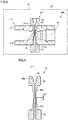
FIG. 3 is a schematic plan view showing a measurement unit according toEmbodiment 1. -
FIG. 4 is a schematic side view of the measurement unit as viewed from the arrow IV shown inFIG. 3 . -
FIG. 5 is a schematic cross-sectional view showing a peripheral configuration of a measurement unit in an analysis device according toEmbodiment 2. -
FIG. 6 is a schematic cross-sectional view showing a guide provided in the analysis device according toEmbodiment 2. - Hereinafter, embodiments of the present disclosure will be described in detail with reference to the attached drawings. In the following embodiments, the same or common parts are denoted by the same reference numerals in the drawings, and the description thereof will not be repeated.
-
FIG. 1 is a perspective view showing an external view of an analysis device according toEmbodiment 1.FIG. 2 is a schematic configuration diagram showing the configuration of the analysis device according toEmbodiment 1. Referring toFIG. 1 andFIG. 2 , ananalysis device 1 according toEmbodiment 1 will be described. - The
analysis device 1 is a device for analyzing a quantitative and/or a concentration, etc., of, for example, a nucleic acid, such as, e.g., an RNA and a DNA involved in a protein synthesis, an amino acid, a peptide, a protein, a lipid, a metabolite, a cell, a structure constituting a part of a cell, a chromosome, a viral particle, a bacterium, and the like. - As shown in
FIG. 1 andFIG. 2 , theanalysis device 1 according toEmbodiment 1 is provided with aliquid collection device 10, a devicemain body 20, and adata processing device 30. - The
liquid collection device 10 is configured such that a small amount of a fluid L of about 1 nL to 100 nL can be collected. The liquid L to be collected by theliquid collection device 10 is, for example, a mixture in which a sample including a nucleic acid and a fluorescent reagent fluorescently labeling the nucleic acid are mixed. By collecting and measuring the pre-mixed mixture, it is possible to omit the operation of mixing the sample and the reagent on the side of theanalysis device 1. - The fluorescent reagent is appropriately selected depending on a sample to be analyzed. As the fluorescent reagent, a reagent including a fluorescent dye, such as, e.g., PicoGreen (registered trademark) and SYBR Green (registered trademark), may be used.
- The
liquid collection device 10 includes amain body 11, aflow channel member 12, and asuction mechanism 14. Themain body 11 accommodates therein thesuction mechanism 14 and a part of theflow channel member 12. - The
flow channel member 12 has oneend 12a and theother end 12b. Theflow channel member 12 is formed with aflow channel 12c through which a liquid L can flow. Theflow channel 12c is formed from the oneend 12a to theother end 12b of theflow channel member 12. - The
flow channel member 12 is formed, for example, in a straight line. Theflow channel member 12 is configured by a translucent cylindrical member. The inner diameter (flow channel diameter) of the cylindrical member is 2.0 mm or less, for example, about 0.2 mm. For theflow channel member 12, for example, a glass capillary may be used. Since the quantity to be handled is an nL-level, the inner diameter of the tubular member is preferably small so that the fluid held in the flow channel has a reasonable liquid length for measurements along the flow channel. - The one
end 12a of theflow channel member 12 is attached to themain body 11. Themain body 11 is provided with a through-hole 13 for connecting theflow channel 12c of theflow channel member 12 and thesuction mechanism 14. - The
suction mechanism 14 is provided to be connected to theflow channel 12c from oneend 12a of theflow channel member 12. Thesuction mechanism 14 is a mechanism for suctioning a liquid sample L from theother end 12b of theflow channel member 12 into theflow channel 12c. Thesuction mechanism 14 suctions a liquid sample L so that the liquid sample L is held in theflow channel 12c. - The
suction mechanism 14 has an actuator provided with a piezoelectric element and a diaphragm driven by the piezoelectric element. The actuator enables thesuction mechanism 14 to suction a liquid sample L such that the fluid L is held within theflow channel 12c by pressurizing and depressurizing theflow channel 12c. As the piezoelectric element, for example, a piezoelectric element may be used. - The
suction mechanism 14 suctions a liquid sample L so that the liquid sample L is held between air layers formed on both end sides of theflow channel 12c. As a result, the liquid sample L is arranged inner than theother end 12b of theflow channel member 12 opened to the external space. Therefore, it is possible to prevent the liquid surface of the liquid sample L from coming into contact with the spatially open outside air. Consequently, the evaporation of the liquid sample L can be reduced. Other than the air layer, any liquid which does not mix with a liquid sample L may be used. The volume change due to the pressurizing/depressurizing of thesuction mechanism 14 can be suppressed, and a liquid sample L can be collected in an appropriate quantity. - Further, a liquid sample L is prevented from being held in one
end 12a of theflow channel member 12. Therefore, as will be described later, when measuring, it is possible to shorten the length of theflow channel member 12 to be inserted when inserting theflow channel member 12 inside thedevice body 20 from theinsertion hole 22. - In the above-described example, a case has been described in which the
suction mechanism 14 collects a mixture in which a sample and a fluorescent reagent are mixed in advance, but the present invention is not limited thereto. Thesuction mechanism 14 may suction two types of liquids of a sample and a fluorescent reagent in this order, and the two types of collected liquids may be mixed in the flow channel. In this case, it is preferable to mix the above-described sample and fluorescent reagent by repeatedly pressurizing and depressurizing the inside of theflow channel 12c while holding the above-described sample and fluorescent reagent in theflow channel 12c by thesuction mechanism 14 - In such cases, it is possible to omit an operation of preparing a mixture in which a sample and a fluorescent reagent are mixed in advance before the suction by the
suction mechanism 14. Further, a mixture can be prepared by controlling the operation of thesuction mechanism 14. - The operation of the
suction mechanism 14 is controlled, for example, by a suctionmechanism control unit 23 provided inside the devicemain body 20. Thesuction mechanism 14 is connected to a suctionmechanism control unit 23 by awiring 24. The suctionmechanism control unit 23 may be provided in themain body 11 of theliquid collection device 10. In this case, thecase wiring 24 and the power supply may also be provided in themain body 11. - The device
main body 20 includes ameasurement unit 40 therein. Themeasurement unit 40 is a unit for measuring a liquid sample L suctioned by thesuction mechanism 14. Note that the detailed configuration of themeasurement unit 40 will be described later with reference toFIG. 3 and FIG. 4 . - The device
main body 20 is provided with aninstallation portion 21 for detachably installing theliquid collection device 10. Theliquid collection device 10 is removed from the devicemain body 20 when collecting a liquid sample L, as indicated by the dashed line inFIG. 1 . Theliquid collection device 10 is installed on the devicemain body 20 when measuring the collected liquid sample L. - The device
main body 20 is configured to allow theliquid collection device 10 to be inserted. Specifically, the devicemain body 20 is provided with aninsertion hole 22 for inserting theflow channel member 12 of theliquid collection device 10 into the inside of the devicemain body 20. When amounting theliquid collection device 10 on theinstallation portion 21, theother end 12b side of theflow channel member 12 is inserted into theinsertion hole 22 to thereby fix themain body 11 to theinstallation portion 21. With this, in the installation state in which theliquid collection device 10 is installed on theinstallation portion 21, theother end 12b side of theflow channel member 12 becomes a state of being inserted into the inside of the devicemain body 20, and the liquid L held in theflow channel member 12 is arranged at the measuring position in themeasurement unit 40. - In the
data processing device 30, a predetermined control program for executing various controls and processing is installed, and thedata processing device 30 is connected to the devicemain body 20. - The
data processing device 30 is provided with adisplay unit 31, anoperation unit 32, acontrol unit 33, and astorage unit 36. Thedisplay unit 31 displays the information for operations, measured results, and the like. Theoperation unit 32 is for setting various parameters related to measurements and instructing various processing. - The
control unit 33 includes ameasurement control unit 34 and adata processing unit 35. Themeasurement control unit 34 controls the operation of themeasurement unit 40. Thedata processing unit 35 executes various arithmetic processing for analyzing a liquid sample L based on the signal received from themeasurement unit 40. Thestorage unit 36 stores the signal received from themeasurement unit 40 and the execution results of thedata processing unit 35. The execution results or the like stored in thestorage unit 36 may be configured to be retrieved from thedata processing device 30 for processing by an external computer or managing data. -
FIG. 3 is a schematic plan view of the measurement unit according toEmbodiment 1.FIG. 4 is a schematic side view of the measurement unit as viewed from the arrow IV shown inFIG. 3 . Referring toFIG. 3 and FIG. 4 , themeasurement unit 40 according toEmbodiment 1 will be described. - As shown in
FIG. 3 and FIG. 4 , themeasurement unit 40 has anirradiation unit 41, alight reception unit 42, anoptical system 43, a firstwavelength selection element 44, a secondwavelength selection element 45, and anaperture member 46. In themeasurement unit 40, optical characteristics of a liquid sample L are detected by thelight reception unit 42 as follows. Note that the optical characteristic is, for example, a fluorescence intensity. - The
irradiation unit 41 irradiates the liquid sample L held in theflow channel member 12 with measurement light. Theirradiation unit 41 emits light including a wavelength band for exciting a fluorescent dye contained in a liquid sample L (mixture) to be analyzed. Theirradiation unit 41 emits, for example, blue visible light having a main wavelength of about 470 nm. For example, an LED can be used as theirradiation unit 41. The measurement light emitted from theirradiation unit 41 is directed toward the firstwavelength selection element 44. - The first
wavelength selection element 44 is arranged on the optical path of the measurement light from theirradiation unit 41 toward theflow channel member 12. The firstwavelength selection element 44 selectively passes the light of a first wavelength band. The firstwavelength selection element 44 is, for example, a band-pass filter. The first wavelength band is a wavelength band for exciting a fluorescent dye contained in a liquid sample L (mixture) to be analyzed. The measurement light passed through the firstwavelength selection element 44 is guided by theoptical system 43. - The
optical system 43 forms at least a passage path of the measurement light, and guides the measurement light irradiated from theirradiation unit 41 to the liquid sample L held in theflow channel member 12. Theoptical system 43 includes, for example, a condenser lens, such as, e.g., a ball lens, while condensing the measurement light passed through the firstwavelength selection element 44, and guides the measurement light to the liquid sample L. - The measurement light collected by the
optical system 43 is limited in the light range by theaperture member 46 before reaching the liquid sample L held in theflow channel member 12. Theaperture member 46 has, for example, a plate-like shape and is arranged in the vicinity of theflow channel member 12 inserted into the inside of the devicemain body 20. - The
aperture member 46 has anopening 46a that defines the irradiation area of the measurement light to be emitted to the liquid sample L. The measurement light passed through theopening 46a is emitted to the liquid sample L. - The liquid sample L held in the flow channel member 12 (flow
channel 12c) extends along theflow channel 12c, and the opening width L2 of theopening 46a along theflow channel 12c is shorter than the length (liquid length) L1 of the liquid sample L held in theflow channel member 12 along theflow channel 12c. Note that the length of the liquid sample L along theflow channel 12c when the trace amount of the liquid sample L is held in theflow channel 12c is approximately 2 mm to 3 mm. - When the opening width is defined in this manner, the measurement light can be emitted only to the portion where the liquid sample L exists, even if the quantity of the liquid sample L to be collected from the target varies.
- As described above, the measurement light emitted to the liquid sample L has a first wavelength band for exciting a fluorescent dye contained in the liquid sample L. Therefore, fluorescence is emitted from the fluorescent dye excited by the measurement light. The portion of the measurement light that has been redirected by the liquid sample L and the
flow channel member 12, as well as the emitted fluorescent light, is directed toward thelight reception unit 42. - The
light reception unit 42 is arranged at a position where theirradiation unit 41 is rotated by approximately 90 degrees around the central axis of theflow channel member 12. Thelight reception unit 42 receives the light from the liquid sample L (mixture) irradiated with the measurement light. Specifically, thelight reception unit 42 receives the light emitted from the fluorescent dye and passed through the secondwavelength selection element 45. - The second
wavelength selection element 45 is arranged on the optical path of the light from the liquid sample L irradiated with the measurement light to thelight reception unit 42. The secondwavelength selection element 45 selectively passes the light of a second wavelength band that differs from the first wavelength band. The second wavelength band is a wavelength region in which the fluorescence emitted from the above-described fluorescent dye has a wavelength range. By passing the light from the liquid sample L toward thelight reception unit 42 through the secondwavelength selection element 45, only the fluorescent light can be introduced into thelight reception unit 42. - With this, the
light reception unit 42 transmits signals detected based on the received fluorescent light to thedata processing unit 35. Thedata processing unit 35 performs arithmetic processing based on the received signal and specifies the quantity and the like of the nucleic acid contained in the sample. In this way, the liquid sample L is analyzed. - As described above, in the
analysis device 1 according to this embodiment, by using theliquid collection device 10 including theflow channel member 12 in which theflow channel 12c is formed and thesuction mechanism 14 as described above, by driving thesuction mechanism 14, it is possible to hold the collected liquid L in theflow channel member 12 while suctioning a trace amount of the liquid L into theflow channel member 12. Further, in a state in which the liquid L is held in theflow channel member 12, by inserting theother end 12b side of theflow channel member 12 into theinsertion hole 22 and installing theliquid collection device 10 on the installation portion of the devicemain body 20, it is possible to arrange the liquid L in the measuring position. As a result, by analyzing a trace amount of the liquid L by the measurement unit, a trace amount of the liquid L can be measured. -
FIG. 5 is a schematic cross-sectional view showing a peripheral configuration of a measurement unit of a device main body according toEmbodiment 2. Note thatFIG. 5 shows ameasurement unit 40A when viewed theirradiation unit 41 from the front side, and omits the first wavelength selection element and the optical system included in themeasurement unit 40A for convenience. - As shown in
FIG. 5 , the analysis device according toEmbodiment 2 differs from the analysis device according toEmbodiment 1 in that theguide 25 and the measurementunit holding unit 51 are provided, and the configuration of themeasurement unit 40A is substantially the same. - The
guide 25 is provided in the devicemain body 20. Specifically, theguide 25 is provided below theinsertion hole 22 provided in the devicemain body 20. Note that the position of theguide 25 is not limited to the position below theinsertion hole 22. The upper portion of theguide 25 may protrude from theinsertion hole 22 to the outside. - The
guide 25 extends in the inserting direction of theflow channel member 12 to guide the insertion of theflow channel member 12. Note that the insertion direction of theflow channel member 12 is a direction perpendicular to the opening surface of theinsertion hole 22. Theguide 25 is held by the measurementunit holding unit 51. Theguide 25 has a firstcylindrical portion 26 and a secondcylindrical portion 27. - The measurement
unit holding unit 51 holds themeasurement unit 40A. The measurementunit holding unit 51 includes afirst plate portion 511 and a second plate portion 512 spaced apart from each other in the inserting direction of theflow channel member 12. Thefirst plate portion 511 and the second plate portion 512 are fixed together so as not to affect the measurements by themeasurement unit 40A. - The
first plate portion 511 and the second plate portion 512 are provided with a through-hole 511a and a through-hole 512a, respectively. The through-hole 511a and the through-hole 512a hold theguide 25. Specifically, the firstcylindrical portion 26 is inserted into and held by the through-hole 511a, and the secondcylindrical portion 27 is inserted into and held by the through-hole 512a. -
FIG. 6 is a schematic cross-sectional view showing a guide provided in the device main body according toEmbodiment 2. Referring toFIG. 6 , the firstcylindrical portion 26 and the secondcylindrical portion 27 provided in theguide 25 will be described in detail. - The first
cylindrical portion 26 and the secondcylindrical portion 27 are arranged side by side in the insertion direction so that the cylindrical shaft is parallel to the insertion direction of theflow channel member 12. The firstcylindrical portion 26 is arranged so that theflow channel member 12 is inserted before the insertion of the secondcylindrical portion 27. - The first
cylindrical portion 26 has anintroduction portion 26a for guiding theother end 12b of theflow channel member 12 to theguide channel 26b. Theintroduction portion 26a is formed so that the inner diameter decreases toward theguide channel 26b. Theguide channel 26b is formed in a straight line along the inserting direction. - The second
cylindrical portion 27 has aguide channel 27b arranged opposite to theguide channel 26b. The diameter of theguide channel 27b is larger than the diameter of theguide channel 26b. - The
other end 12b of theflow channel member 12 introduced in theintroduction portion 26a enters into the inside of theguide channel 27b through theguide channel 26b by being further inserted. - Between the first
cylindrical portion 26 and the secondcylindrical portion 27 in the inserting direction, a gap GP is formed. The size of the gap GP in the inserting direction is shorter than the length of the liquid sample L held in theflow channel member 12 along theflow channel 12c in the inserting direction. The gap GP corresponds to theopening 46a inEmbodiment 1, and the irradiated area where the liquid sample L is irradiated is defined by the gap GP. The light from the liquid sample L is directed from the gap GP to thelight reception unit 42. In this manner, theguide 25 constitutes an aperture member for limiting the irradiation area of the measurement light irradiating the liquid sample L. - Even when configured as described above, the analysis device according to
Embodiment 2 has substantially the same effects as those ofEmbodiment 1. Further, the provision of theguide 25 makes it easier to position the liquid sample L at the measuring position on the optical path of the measurement light. Furthermore, by configuring a diaphragm by theguide 25, it is possible to reduce the number of components. - In
Embodiment 2 described above, an example is exemplified in which theguide 25 is configured by two cylindrical portions separated from each other, but the present invention is not limited thereto, and theguide 25 may be configured by one cylindrical portion. In this case, it is preferable to provide an opening that defines the irradiation area of the measurement light and a window that allows the light from liquid sample L to pass through the window at the peripheral wall portion of the cylindrical portion. - In
Embodiments - Referring back to
FIG. 2 , theanalysis device 1 is provided with a liquidlength measurement mechanism 50 for correcting an error in the quantity of the liquid sample to be measured. The liquidlength measurement mechanism 50 is preferably a camera or a sensor for measuring the liquid length of a trace of the fluid held in the flow channel, and the liquid length is measured from the image obtained by the camera or the sensor. - In a conventional gravimetric method used for calibration of a liquid collection device, a liquid on the order of nL dries, making the calibration difficult. Since the suction mechanism constituting the trace liquid collection device of the present invention measures the liquid sample held in the flow channel, the influence of the drying becomes small, which enables an accurate calibration. This exerts an effect of obtaining a high-precision suction amount. As an inspection operation before sampling a liquid, the trace liquid collection device corrects the condition that the liquid amount becomes the desired amount by the suction control mechanism in a case where the liquid amount calculated by the calculation mechanism from the liquid length of the liquid sample held in the flow channel becomes different from the predetermined liquid amount when the suction mechanism is operated under the predetermined condition. From the subsequent measurements, liquid sampling is performed under the condition corrected and calculated.
- Since the inner diameter of the flow channel is known, the volume of the held liquid sample can be calculated by measuring the liquid length of the liquid sample. The error can be corrected based on the calculated volume of the liquid sample. As a correction for an error, a correction of the suction operation amount of the suction mechanism and a correction of the final concentration by the mixing ratio of the sample to the fluorescent reagent can be performed.
- The suction control mechanism constituting the trace liquid collection device can instruct the suction mechanism to perform the additional suction when the suctioned liquid amount is smaller than a preset liquid amount. As a result, it is possible to obtain a desired liquid amount, thereby eliminating the labor of retesting due to a failure and enabling the test with a minimum amount of the liquid sample.
- On the other hand, when the suctioned liquid amount is larger than a predetermined liquid amount, a warning can be displayed so as not to perform further suction. This has the effect of preventing the trace liquid collection device from failing.
- The trace liquid collection device may be a two-fluid mixing type liquid collection device that suctions two types of liquid samples into a flow channel. In this case, the suction control mechanism may be able to instruct the suction mechanism the second suction amount with respect to the first suction amount so that the mixing ratio of the two types of liquid samples becomes the desired ratio. As a result, it becomes possible to obtain a desired mixing ratio. Therefore, retesting due to a failure can be eliminated, which makes it possible to perform a test with a minimum amount of a liquid sample.
- In this measurement, the environmental conditions (temperature, humidity, and atmospheric pressure) to be measured are monitored, and the setting conditions of a suction mechanism are set according to the monitored environmental conditions. In a case where a liquid sample is extremely small in amount, a failure of a suction mechanism or a connection failure of the flow channel member is notified.
- The accuracy of mixing the liquid sample and the fluorescent reagent to be suctioned into the flow channel affects the concentration (final concentration) of the nucleic acid contained in the mixture to be measured. When an error occurs in the amount to be actually suctioned due to the physical properties (particularly the viscosity) of the liquid suctioned into the flow channel when performing a suction operation of suctioning a predetermined amount, an error occurs in the final concentration of the nucleic acid in the mixture, and the intensity of the light measured from the mixture differs. When the nucleic acid contained in a liquid sample to be measured is quantified with high accuracy, the error needs to be corrected.
- A correction for the final concentration will be described using an example in which a liquid sample and a fluorescent reagent are mixed equal amounts. In a state in which the mixed liquid sample is suctioned, the liquid length of the sample fluid is measured. The liquid length of the mixture with the fluorescent reagent to be subsequently suctioned is measured. Since the same volume is suctioned and mixed in equal amounts, the liquid length of the fluorescent reagent is the same as that of the liquid sample.
- By using a calibration curve prepared by a standard solution having a known concentration, a final concentration is calculated from the measured light intensity and applying a mixing ratio based on the measured liquid length to the final concentration, the concentration of a nucleic acid can be calculated.
- For example, when a liquid sample having a nucleic acid concentration of 20 ng/µL and a fluorescent reagent are mixed in equal amounts (5:5), the final concentration becomes 10 ng/µL, However, when the ratio actually suctioned and mixed is 4:6 in a ratio of the liquid length calculated by a liquid length measurement mechanism, the concentration becomes thin and the measured light intensity becomes weak. Therefore, the concentration obtained from the calibration curve becomes 16 ng/µL. On the other hand, when converting by applying the mixing ratio (4:6) based on the measured liquid length, an accurate concentration can be calculated.
- The embodiments disclosed herein are illustrative in all respects and not restrictive. The scope of the present invention is indicated by claims, and includes all modifications within the meanings and ranges equivalent to those of claims.
-
- 1:
- Analysis device
- 10:
- Liquid collection device
- 11:
- Main body
- 12:
- Flow channel member
- 12a:
- One end
- 12b;
- The other end
- 12c:
- Flow channel
- 13:
- Through-hole
- 14:
- Suction mechanism
- 20, 20A:
- Device main body
- 21:
- Installation portion
- 22:
- Insertion hole
- 23:
- Suction mechanism control unit
- 24:
- Wiring
- 25:
- Guide
- 26:
- First cylindrical portion
- 26a:
- Introduction portion
- 26b:
- Guide channel
- 27:
- Second cylindrical portion
- 27b:
- Guide channel
- 30:
- Data processing device
- 31:
- Display unit
- 32:
- Operation unit
- 33:
- Control unit
- 34:
- Measurement control unit
- 35:
- Data processing unit
- 36:
- Storage unit
- 40:
- Measurement unit
- 41:
- Irradiation unit
- 42:
- Light reception unit
- 43:
- Optical system
- 44:
- First wavelength selection element
- 45:
- Second wavelength selection element
- 46:
- Aperture member
- 46a:
- Opening
- 50:
- Liquid length measurement mechanism
Claims (24)
- An analysis device comprising:a flow channel;a suction mechanism connected to one end of the flow channel, the suction mechanism being configured to introduce a trace amount of a liquid sample from the other end of the flow channel to an inside of the flow channel and hold the liquid sample in a part of the flow channel; anda measurement unit configured such that a light irradiation unit for irradiating the liquid sample held in the part of the flow channel with light and a light reception unit for receiving light from the liquid sample are positioned around the liquid sample,wherein the measurement unit is provided with an aperture member for limiting the light directed from the light irradiation unit toward the liquid sample, the aperture member having an opening width shorter than a liquid length of the liquid sample in the flow channel, and the liquid sample being held in the flow channel.
- The analysis device as recited in claim 1, further comprising:a liquid collection device configured to collect a trace amount of a fluid; anda device main body configured to allow the liquid collection device to be inserted,wherein the liquid collection device includes a flow channel member in which the flow channel is formed and the suction mechanism,wherein the device main body includes the measurement unit therein, andwherein the measurement unit measures the liquid sample held in the flow channel member inserted into an inside of the device main body.
- The analysis device as recited in claim 1 or 2,
wherein the suction mechanism suctions the liquid sample so that the liquid sample is held between air layers or liquid layers formed on both end sides of the flow channel. - The analysis device as recited in claim 3,
wherein the liquid sample is a mixture in which a sample including a nucleic acid, an amino acid, a peptide, a protein, a lipid, a metabolite, a cell, a structural body constituting a part of a cell, a chromosome, a viral particle, and a bacterium, and a fluorescent reagent for fluorescently labeling the sample, a molecular reagent such as an antibody having a fluorescently labeled specific binding ability, or a luminescent reagent for luminescently labeling are mixed. - The analysis device as recited in claim 3,
wherein the suction mechanism suctions two types of liquids of a sample including a nucleic acid, an amino acid, a peptide, a protein, a lipid, a metabolite, a cell and a fluorescent reagent for fluorescently labeling the sample or a luminescent reagent for luminescent labeling in this order, and mixes the two types of suctioned liquids in the flow channel, and
wherein the measurement unit measures a mixture in which the two types of liquids are mixed. - The analysis device as recited in claim 5,
wherein the suction mechanism repeatedly pressurizes and depressurizes the inside of the flow channel while holding the sample and the fluorescent reagent or the luminescent reagent in the flow channel to mix the sample and the fluorescent reagent. - The analysis device as recited in claim 1, further comprising:
a liquid length measurement unit configured to measure a liquid length of the liquid sample held in the flow channel, the liquid length measurement means calculating a volume of the liquid sample. - The analysis device as recited in claim 7,
wherein a suction amount of the liquid sample by the suction mechanism is corrected based on a calculated volume of the liquid sample. - The analysis device as recited in claim 7,
wherein a result of the measurement is corrected based on a calculated volume of the liquid sample. - The analysis device as recited in claim 2,
wherein the device main body is provided with a guide for guiding insertion of the flow channel member, the guide extending in an insertion direction of the flow channel member, and
wherein the aperture member is configured by the guide. - The analysis device as recited in claim 1,
wherein a suction amount of the liquid sample is 1 nL to 100 nL. - The analysis device as recited in claim 1,
wherein a hollow cross-section of the flow channel is circular. - The analysis device as recited in claim 1,
wherein an inner diameter of the flow channel is 2.0 mm or less. - An analysis method comprising:introducing a trace amount of a liquid sample into an inside of a flow channel from the other end of the flow channel connected to one end of the flow channel, and holding the liquid sample in a part of the flow channel;irradiating the liquid sample held in a part of the flow channel with light from a light irradiation unit arranged so as to be positioned around the liquid sample with respect to the liquid sample;receiving light from the liquid sample with a light reception unit arranged so as to be positioned around the liquid sample with respect to the liquid sample; andmeasuring light from the light irradiation unit by limiting the light from the light irradiation unit toward the liquid sample by an aperture member having an opening width shorter than a liquid length of the liquid sample in the flow channel, the liquid sample being held in the flow channel.
- The analysis method as recited in claim 14,
wherein the liquid sample is suctioned so that the liquid sample is held between air layers or liquid layers formed on both end sides of the flow channel. - The analysis method as recited in claim 14,
wherein a suction amount of the liquid sample is 1 nL to 100 nL. - The analysis method as recited in claim 14,
wherein the liquid sample is a mixture in which a sample including a nucleic acid, an amino acid, a peptide, a protein, a lipid, a metabolite, a cell and a fluorescent reagent for fluorescently labeling the sample or a luminescent reagent for luminescently labeling the sample are mixed. - The analysis method as recited in claim 14, further comprising:
wherein two types of liquids of a sample including a nucleic acid, an amino acid, a peptide, a protein, a lipid, a metabolite, a cell and a fluorescent reagent for fluorescently labeling the sample or a luminescent reagent for luminescent labeling are suctioned by a suction mechanism in this order, the two types of liquids suctioned in the flow channel are mixed, and a mixture in which the two types of liquids are mixed are measured. - The analysis method as recited in claim 18,
wherein the sample and the fluorescent reagent or the luminescent reagent are mixed by repeatedly pressurizing and depressurizing the inside of the flow channel while holding the sample and the luminescent reagent or the luminescent reagent in the flow channel. - The analysis method as recited in claim 14,
wherein a liquid length of the liquid sample held in the flow channel is measured and a volume of the liquid sample is calculated. - The analysis method as recited in claim 20,
wherein a suction amount of the liquid sample is corrected based on a calculated volume of the liquid sample. - The analysis method as recited in claim 20,
wherein a result of the measurement is corrected based on a calculated volume of the liquid sample. - A trace liquid collection device comprising:a flow channel;a suction mechanism connected to one end of the flow channel, the suction mechanism being configured to introduce a trace amount of a liquid sample from the other end of the flow channel to an inside of the flow channel and hold the liquid sample in a part of the flow channel;a liquid length measurement means configured to measure a liquid length of the liquid sample held in the flow channel; anda suction control mechanism configured to calculate a volume of the liquid sample and feed back the calculated volume to the suction mechanism.
- A trace liquid collection method comprising:introducing a trace amount of a liquid sample to an inside of a flow channel from the other end of the flow channel connected to one end of the flow channel;holding the liquid sample in a part of the flow channel;measuring a liquid length of the liquid sample held in the flow channel;calculating a volume of the liquid sample; andfeeding back the calculated volume to a suction mechanism.
Applications Claiming Priority (2)
| Application Number | Priority Date | Filing Date | Title |
|---|---|---|---|
| JP2018163536 | 2018-08-31 | ||
| PCT/JP2019/031848 WO2020045080A1 (en) | 2018-08-31 | 2019-08-13 | Analysis device, analysis method, trace liquid collection device, and trace liquid collection method |
Publications (2)
| Publication Number | Publication Date |
|---|---|
| EP3845882A1 true EP3845882A1 (en) | 2021-07-07 |
| EP3845882A4 EP3845882A4 (en) | 2022-05-04 |
Family
ID=69643124
Family Applications (1)
| Application Number | Title | Priority Date | Filing Date |
|---|---|---|---|
| EP19855012.1A Pending EP3845882A4 (en) | 2018-08-31 | 2019-08-13 | ANALYSIS DEVICE, ANALYSIS METHOD, TRACE LIQUID COLLECTION DEVICE AND TRACE LIQUID COLLECTION METHOD |
Country Status (5)
| Country | Link |
|---|---|
| US (1) | US12163885B2 (en) |
| EP (1) | EP3845882A4 (en) |
| JP (1) | JP7064217B2 (en) |
| CN (1) | CN112639432A (en) |
| WO (1) | WO2020045080A1 (en) |
Family Cites Families (48)
| Publication number | Priority date | Publication date | Assignee | Title |
|---|---|---|---|---|
| JPS6086439A (en) | 1983-10-19 | 1985-05-16 | Toshiba Corp | Optical quantifying device of very small quantity |
| JPH0213857A (en) * | 1988-06-30 | 1990-01-18 | Shimadzu Corp | Spectroscopic analyzer |
| JP3091213B2 (en) * | 1990-10-26 | 2000-09-25 | オリンパス光学工業株式会社 | Reagent evaporation prevention method |
| US5282473A (en) * | 1992-11-10 | 1994-02-01 | Critikon, Inc. | Sidestream infrared gas analyzer requiring small sample volumes |
| EP0619476B1 (en) * | 1992-12-19 | 1999-09-22 | Boehringer Mannheim Gmbh | Device for detection of a fluidic interface in a transparent measuring tube |
| SE9700207D0 (en) * | 1997-01-24 | 1997-01-24 | Erik Litborn | A method of preventing evaporation from liquid samples in small volumes |
| US6235534B1 (en) | 1998-04-27 | 2001-05-22 | Ronald Frederich Brookes | Incremental absorbance scanning of liquid in dispensing tips |
| EP1054250B1 (en) * | 1999-01-25 | 2002-09-04 | Hamamatsu Photonics K.K. | Pipette adaptor, pipette for absorbance measurement, method and apparatus for absorbance measurement |
| WO2000068671A2 (en) * | 1999-05-12 | 2000-11-16 | Aclara Biosciences, Inc. | Multiplexed fluorescent detection in microfluidic devices |
| US6838680B2 (en) * | 1999-05-12 | 2005-01-04 | Aclara Biosciences, Inc. | Multiplexed fluorescent detection in microfluidic devices |
| US6441387B1 (en) * | 1999-06-30 | 2002-08-27 | The United States Of America As Represented By The Secretary Of The Army | Biological aerosol trigger (BAT) |
| DK2959774T3 (en) * | 2003-03-28 | 2019-05-13 | Inguran Llc | PROCEDURE FOR CRYCONSERVATION OF SEAT CELLS |
| JP2005147826A (en) * | 2003-11-14 | 2005-06-09 | Hamamatsu Photonics Kk | Fluorescence measurement instrument |
| US7869011B2 (en) * | 2003-12-22 | 2011-01-11 | Novo Norkisk A/S | Apparatus and methods for analysis and sorting of particles such as polymer beads |
| CN100594382C (en) | 2004-03-23 | 2010-03-17 | 松下电器产业株式会社 | Stirring method, reaction vessel, measuring device using same, and measuring method |
| JP4615342B2 (en) | 2004-03-23 | 2011-01-19 | パナソニック株式会社 | Stirring method, cell, measuring device using the same, and measuring method |
| JP2005326365A (en) | 2004-05-17 | 2005-11-24 | Sigma Meltec Ltd | Test liquid quantity measuring device |
| JP4363649B2 (en) * | 2004-09-30 | 2009-11-11 | 富士フイルム株式会社 | Measuring apparatus and method using total reflection attenuation |
| JP4476906B2 (en) * | 2005-09-02 | 2010-06-09 | 富士フイルム株式会社 | Dispensing device |
| US7277167B2 (en) | 2005-09-13 | 2007-10-02 | Agilent Technologies, Inc. | Modular cuvettes and methods for use thereof |
| JP2007121275A (en) * | 2005-09-27 | 2007-05-17 | Fujifilm Corp | Microchip, liquid mixing method and blood test method using the microchip |
| US20070081159A1 (en) | 2005-10-11 | 2007-04-12 | Giffin Kristin M | Apparatus and methods for evaluating an optical property of a liquid sample |
| US8072603B2 (en) * | 2006-02-02 | 2011-12-06 | E I Spectra, LLC | Fluorescence-activated cell detector |
| WO2007113895A1 (en) | 2006-04-03 | 2007-10-11 | Shimadzu Corporation | Optical measurement instrument for trace liquid sample |
| CN101523191B (en) | 2006-10-06 | 2012-06-06 | 株式会社岛津制作所 | Spectrophotometer |
| JP5026849B2 (en) * | 2007-04-20 | 2012-09-19 | 株式会社日立製作所 | Chemiluminescence measuring device |
| CN201247197Y (en) | 2008-08-19 | 2009-05-27 | 上海现科分光仪器有限公司 | Improved structure of spectrophotometer injector |
| US8232111B2 (en) * | 2009-01-29 | 2012-07-31 | Empire Technology Development Llc | Micropipette, micropipette system, and method for using micropipette |
| CN201425580Y (en) | 2009-03-28 | 2010-03-17 | 西尔艾力·依米提 | flow spectrophotometer |
| WO2010122990A1 (en) * | 2009-04-20 | 2010-10-28 | ユニバーサル・バイオ・リサーチ株式会社 | Tube for measuring bio-related substance and quantifying system |
| JP5904940B2 (en) * | 2010-06-22 | 2016-04-20 | ユニバーサル・バイオ・リサーチ株式会社 | Composition for preventing evaporation of reaction solution during nucleic acid amplification reaction |
| JP5666277B2 (en) * | 2010-12-10 | 2015-02-12 | 富士フイルム株式会社 | Analysis chip |
| JP5797427B2 (en) * | 2011-03-10 | 2015-10-21 | 富士フイルム株式会社 | Detection method and detection apparatus |
| KR102045090B1 (en) * | 2011-05-16 | 2019-12-02 | 유니바사루 바이오 리사치 가부시키가이샤 | Optical measurement device for reaction vessel and method therefor |
| EP2921861B1 (en) * | 2012-11-16 | 2021-07-21 | Universal Bio Research Co., Ltd. | Linear movement type reaction processing device and method for same |
| US9212081B2 (en) * | 2012-11-21 | 2015-12-15 | Corning Incorporated | Methods of cutting a laminate strengthened glass substrate |
| US9488579B2 (en) * | 2013-01-22 | 2016-11-08 | Tecan Trading Ag | Optical measuring apparatus and method for the analysis of samples contained in liquid drops |
| US9488576B2 (en) * | 2013-01-22 | 2016-11-08 | Tecan Trading Ag | Optical measuring apparatus and method for the analysis of samples contained in liquid drops |
| US8912007B2 (en) * | 2013-01-22 | 2014-12-16 | Tecan Trading Ag | Optical measuring apparatus and method for the analysis of samples contained in liquid drops |
| CA2905178A1 (en) | 2013-03-15 | 2014-09-18 | Hycor Biomedical, Inc. | Device and associated methods for performing luminescence and fluorescence measurements of a sample |
| GB2530446B (en) * | 2013-07-08 | 2018-06-13 | Hitachi High Tech Corp | Capillary electrophoresis device |
| GB2525679A (en) | 2014-05-02 | 2015-11-04 | Univ Singapore | A disposable measurement tip and method for use thereof |
| JP6313123B2 (en) * | 2014-05-28 | 2018-04-18 | 東京エレクトロン株式会社 | Measuring apparatus and measuring method |
| GB2535140A (en) * | 2015-01-09 | 2016-08-17 | Page Brian | Pipette tip, pipette, apparatus and kit for light measurement |
| CN106053148B (en) * | 2015-04-02 | 2018-04-06 | 无锡市凯顺医疗器械制造有限公司 | A kind of closed body fluid indwelling device of portable disposable |
| US10883926B2 (en) * | 2016-04-08 | 2021-01-05 | Universal Bio Research Co., Ltd. | General-purpose optical measuring device and method of same |
| US11135585B2 (en) * | 2016-06-10 | 2021-10-05 | Sony Corporation | Fluid control device, microparticle measurement device, and fluid control method |
| WO2018181481A1 (en) * | 2017-03-28 | 2018-10-04 | ユニバーサル・バイオ・リサーチ株式会社 | Photometric dispensing nozzle unit, photometric dispensing apparatus, and photometric dispensing method |
-
2019
- 2019-08-13 US US17/272,022 patent/US12163885B2/en active Active
- 2019-08-13 CN CN201980056195.2A patent/CN112639432A/en active Pending
- 2019-08-13 WO PCT/JP2019/031848 patent/WO2020045080A1/en not_active Ceased
- 2019-08-13 EP EP19855012.1A patent/EP3845882A4/en active Pending
- 2019-08-13 JP JP2020539322A patent/JP7064217B2/en active Active
Also Published As
| Publication number | Publication date |
|---|---|
| CN112639432A (en) | 2021-04-09 |
| WO2020045080A1 (en) | 2020-03-05 |
| EP3845882A4 (en) | 2022-05-04 |
| JPWO2020045080A1 (en) | 2021-09-02 |
| US12163885B2 (en) | 2024-12-10 |
| JP7064217B2 (en) | 2022-05-10 |
| US20210349022A1 (en) | 2021-11-11 |
Similar Documents
| Publication | Publication Date | Title |
|---|---|---|
| US11693019B2 (en) | Automated liquid-phase immunoassay apparatus | |
| EP3296718B1 (en) | Station for use with a test apparatus having integrated reaction and detection means | |
| JP4771864B2 (en) | Biochemical analyzer | |
| US20210311033A1 (en) | Automated liquid-phase immunoassay apparatus and method therefor | |
| JP4969060B2 (en) | Automatic analyzer | |
| GB2433602A (en) | Combined titration and pH electrode for the preparation of liquid samples in particular for NMR spectroscopy | |
| JP2000266759A (en) | Chemical analyzer and chemical analysis system | |
| US11125738B2 (en) | Blood sample analysis systems and methods | |
| CN102239405A (en) | Method for determining an analyte in a water sample by means of a mobile water analysis arrangement | |
| US20120224179A1 (en) | Pipette, apparatus and kit for light measurement and method | |
| US10871474B2 (en) | System and method for analyzing biological fluid in multiple cuvettes | |
| JP2004325462A (en) | Chemical analyzer and chemical analysis system | |
| KR20150056479A (en) | Station for test device with integrated reaction and detection means | |
| CN105874053A (en) | Multi-well cuvette provided with integrated reaction and detection means | |
| WO2015111443A1 (en) | Nucleic acid analyzing device | |
| US20130299686A1 (en) | Luminometer and methods of operation | |
| US12163885B2 (en) | Analysis device, analysis method, trace liquid collection device, and trace liquid collection method | |
| CN110073202B (en) | Method and system for measurements with high time resolution in high throughput screening | |
| US20240183846A1 (en) | Method for analyzing liquid immune response using magnetic beads | |
| CN205958459U (en) | Full -automatic liquid sampling four -channel atomic fluorescence spectrometer | |
| EP3487624A1 (en) | Portable kit for automated immunoenzymatic assays | |
| JP2008281526A (en) | Target substance detection device having bubble detection function and bubble detection method | |
| Ozcelik et al. | A Universal Optical Microanalysis Platform Based on Micropipette Tips | |
| WO2020157789A1 (en) | Analysis device | |
| WO2025064143A1 (en) | Method of performing bioassays |
Legal Events
| Date | Code | Title | Description |
|---|---|---|---|
| STAA | Information on the status of an ep patent application or granted ep patent |
Free format text: STATUS: THE INTERNATIONAL PUBLICATION HAS BEEN MADE |
|
| STAA | Information on the status of an ep patent application or granted ep patent |
Free format text: STATUS: REQUEST FOR EXAMINATION WAS MADE |
|
| PUAI | Public reference made under article 153(3) epc to a published international application that has entered the european phase |
Free format text: ORIGINAL CODE: 0009012 |
|
| 17P | Request for examination filed |
Effective date: 20210325 |
|
| AK | Designated contracting states |
Kind code of ref document: A1 Designated state(s): AL AT BE BG CH CY CZ DE DK EE ES FI FR GB GR HR HU IE IS IT LI LT LU LV MC MK MT NL NO PL PT RO RS SE SI SK SM TR |
|
| DAV | Request for validation of the european patent (deleted) | ||
| DAX | Request for extension of the european patent (deleted) | ||
| REG | Reference to a national code |
Ref country code: DE Ref legal event code: R079 Free format text: PREVIOUS MAIN CLASS: G01N0001000000 Ipc: G01N0021050000 |
|
| A4 | Supplementary search report drawn up and despatched |
Effective date: 20220407 |
|
| RIC1 | Information provided on ipc code assigned before grant |
Ipc: G01N 21/03 20060101ALI20220401BHEP Ipc: G01N 21/11 20060101ALI20220401BHEP Ipc: G01N 35/10 20060101ALI20220401BHEP Ipc: G01N 21/64 20060101ALI20220401BHEP Ipc: G01N 21/05 20060101AFI20220401BHEP |
|
| P01 | Opt-out of the competence of the unified patent court (upc) registered |
Effective date: 20230502 |
|
| STAA | Information on the status of an ep patent application or granted ep patent |
Free format text: STATUS: EXAMINATION IS IN PROGRESS |
|
| 17Q | First examination report despatched |
Effective date: 20240416 |