EP3845840B1 - Seitliche zugangsplatte für ein gerät - Google Patents
Seitliche zugangsplatte für ein gerät Download PDFInfo
- Publication number
- EP3845840B1 EP3845840B1 EP20212596.9A EP20212596A EP3845840B1 EP 3845840 B1 EP3845840 B1 EP 3845840B1 EP 20212596 A EP20212596 A EP 20212596A EP 3845840 B1 EP3845840 B1 EP 3845840B1
- Authority
- EP
- European Patent Office
- Prior art keywords
- attachment feature
- access panel
- side access
- appliance cabinet
- appliance
- Prior art date
- Legal status (The legal status is an assumption and is not a legal conclusion. Google has not performed a legal analysis and makes no representation as to the accuracy of the status listed.)
- Active
Links
Images






Classifications
-
- F—MECHANICAL ENGINEERING; LIGHTING; HEATING; WEAPONS; BLASTING
- F25—REFRIGERATION OR COOLING; COMBINED HEATING AND REFRIGERATION SYSTEMS; HEAT PUMP SYSTEMS; MANUFACTURE OR STORAGE OF ICE; LIQUEFACTION SOLIDIFICATION OF GASES
- F25D—REFRIGERATORS; COLD ROOMS; ICE-BOXES; COOLING OR FREEZING APPARATUS NOT OTHERWISE PROVIDED FOR
- F25D23/00—General constructional features
- F25D23/006—General constructional features for mounting refrigerating machinery components
-
- F—MECHANICAL ENGINEERING; LIGHTING; HEATING; WEAPONS; BLASTING
- F25—REFRIGERATION OR COOLING; COMBINED HEATING AND REFRIGERATION SYSTEMS; HEAT PUMP SYSTEMS; MANUFACTURE OR STORAGE OF ICE; LIQUEFACTION SOLIDIFICATION OF GASES
- F25D—REFRIGERATORS; COLD ROOMS; ICE-BOXES; COOLING OR FREEZING APPARATUS NOT OTHERWISE PROVIDED FOR
- F25D23/00—General constructional features
-
- F—MECHANICAL ENGINEERING; LIGHTING; HEATING; WEAPONS; BLASTING
- F25—REFRIGERATION OR COOLING; COMBINED HEATING AND REFRIGERATION SYSTEMS; HEAT PUMP SYSTEMS; MANUFACTURE OR STORAGE OF ICE; LIQUEFACTION SOLIDIFICATION OF GASES
- F25D—REFRIGERATORS; COLD ROOMS; ICE-BOXES; COOLING OR FREEZING APPARATUS NOT OTHERWISE PROVIDED FOR
- F25D23/00—General constructional features
- F25D23/003—General constructional features for cooling refrigerating machinery
-
- F—MECHANICAL ENGINEERING; LIGHTING; HEATING; WEAPONS; BLASTING
- F25—REFRIGERATION OR COOLING; COMBINED HEATING AND REFRIGERATION SYSTEMS; HEAT PUMP SYSTEMS; MANUFACTURE OR STORAGE OF ICE; LIQUEFACTION SOLIDIFICATION OF GASES
- F25D—REFRIGERATORS; COLD ROOMS; ICE-BOXES; COOLING OR FREEZING APPARATUS NOT OTHERWISE PROVIDED FOR
- F25D11/00—Self-contained movable devices, e.g. domestic refrigerators
- F25D11/02—Self-contained movable devices, e.g. domestic refrigerators with cooling compartments at different temperatures
-
- F—MECHANICAL ENGINEERING; LIGHTING; HEATING; WEAPONS; BLASTING
- F25—REFRIGERATION OR COOLING; COMBINED HEATING AND REFRIGERATION SYSTEMS; HEAT PUMP SYSTEMS; MANUFACTURE OR STORAGE OF ICE; LIQUEFACTION SOLIDIFICATION OF GASES
- F25D—REFRIGERATORS; COLD ROOMS; ICE-BOXES; COOLING OR FREEZING APPARATUS NOT OTHERWISE PROVIDED FOR
- F25D23/00—General constructional features
- F25D23/02—Doors; Covers
- F25D23/025—Secondary closures
-
- F—MECHANICAL ENGINEERING; LIGHTING; HEATING; WEAPONS; BLASTING
- F25—REFRIGERATION OR COOLING; COMBINED HEATING AND REFRIGERATION SYSTEMS; HEAT PUMP SYSTEMS; MANUFACTURE OR STORAGE OF ICE; LIQUEFACTION SOLIDIFICATION OF GASES
- F25D—REFRIGERATORS; COLD ROOMS; ICE-BOXES; COOLING OR FREEZING APPARATUS NOT OTHERWISE PROVIDED FOR
- F25D23/00—General constructional features
- F25D23/06—Walls
-
- F—MECHANICAL ENGINEERING; LIGHTING; HEATING; WEAPONS; BLASTING
- F25—REFRIGERATION OR COOLING; COMBINED HEATING AND REFRIGERATION SYSTEMS; HEAT PUMP SYSTEMS; MANUFACTURE OR STORAGE OF ICE; LIQUEFACTION SOLIDIFICATION OF GASES
- F25D—REFRIGERATORS; COLD ROOMS; ICE-BOXES; COOLING OR FREEZING APPARATUS NOT OTHERWISE PROVIDED FOR
- F25D23/00—General constructional features
- F25D23/06—Walls
- F25D23/062—Walls defining a cabinet
-
- F—MECHANICAL ENGINEERING; LIGHTING; HEATING; WEAPONS; BLASTING
- F25—REFRIGERATION OR COOLING; COMBINED HEATING AND REFRIGERATION SYSTEMS; HEAT PUMP SYSTEMS; MANUFACTURE OR STORAGE OF ICE; LIQUEFACTION SOLIDIFICATION OF GASES
- F25D—REFRIGERATORS; COLD ROOMS; ICE-BOXES; COOLING OR FREEZING APPARATUS NOT OTHERWISE PROVIDED FOR
- F25D29/00—Arrangement or mounting of control or safety devices
-
- F—MECHANICAL ENGINEERING; LIGHTING; HEATING; WEAPONS; BLASTING
- F25—REFRIGERATION OR COOLING; COMBINED HEATING AND REFRIGERATION SYSTEMS; HEAT PUMP SYSTEMS; MANUFACTURE OR STORAGE OF ICE; LIQUEFACTION SOLIDIFICATION OF GASES
- F25D—REFRIGERATORS; COLD ROOMS; ICE-BOXES; COOLING OR FREEZING APPARATUS NOT OTHERWISE PROVIDED FOR
- F25D2201/00—Insulation
- F25D2201/10—Insulation with respect to heat
- F25D2201/14—Insulation with respect to heat using subatmospheric pressure
-
- F—MECHANICAL ENGINEERING; LIGHTING; HEATING; WEAPONS; BLASTING
- F25—REFRIGERATION OR COOLING; COMBINED HEATING AND REFRIGERATION SYSTEMS; HEAT PUMP SYSTEMS; MANUFACTURE OR STORAGE OF ICE; LIQUEFACTION SOLIDIFICATION OF GASES
- F25D—REFRIGERATORS; COLD ROOMS; ICE-BOXES; COOLING OR FREEZING APPARATUS NOT OTHERWISE PROVIDED FOR
- F25D2323/00—General constructional features not provided for in other groups of this subclass
- F25D2323/002—Details for cooling refrigerating machinery
- F25D2323/0026—Details for cooling refrigerating machinery characterised by the incoming air flow
- F25D2323/00267—Details for cooling refrigerating machinery characterised by the incoming air flow through the side
-
- F—MECHANICAL ENGINEERING; LIGHTING; HEATING; WEAPONS; BLASTING
- F25—REFRIGERATION OR COOLING; COMBINED HEATING AND REFRIGERATION SYSTEMS; HEAT PUMP SYSTEMS; MANUFACTURE OR STORAGE OF ICE; LIQUEFACTION SOLIDIFICATION OF GASES
- F25D—REFRIGERATORS; COLD ROOMS; ICE-BOXES; COOLING OR FREEZING APPARATUS NOT OTHERWISE PROVIDED FOR
- F25D2323/00—General constructional features not provided for in other groups of this subclass
- F25D2323/002—Details for cooling refrigerating machinery
- F25D2323/0027—Details for cooling refrigerating machinery characterised by the out-flowing air
- F25D2323/00277—Details for cooling refrigerating machinery characterised by the out-flowing air from the side
Definitions
- the present disclosure generally relates to an appliance, and more specifically, to a side access panel for an appliance.
- Document EP2878905A1 discloses a refrigerator according to the preamble of claim 1, comprising a main body comprising an inner liner having a storage compartment defined therein, an outer liner arranged to form an external appearance of the refrigerator and an insulation member filled between the inner liner and the outer liner.
- the refrigerator further comprises a compressor disposed in a machinery compartment and flow channel devices provided at opposite sides of the machinery compartment such that external air is introduced into the machinery compartment, flows along the machinery compartment and is discharged from the machinery compartment.
- Each flow channel device extends through the insulation member filled between the outer liner and an inner wall of the machinery compartment and comprises a machinery compartment inner wall assembly, a case unit disposed between the outer liner and the machinery compartment inner wall assembly and a cover unit.
- Document WO2009/041778A2 discloses a refrigerator comprising a case having a cooling chamber, a machine room disposed on a rear bottom portion of the case and configured to accommodate a compressor therein, a condenser disposed on a rear surface of the case and a heat emission unit configured to guide external air of the case for heat emission of the compressor and the condenser.
- the heat emission unit comprises a machine room cover configured to cover the machine room and having a plurality of first vents, a condenser case configured to fix the condenser accommodated therein onto a wall surface of the case and having a plurality of second vents, a blowing fan configured to generate a flow of air passing through the first and second vents and a communication portion configured to communicate an inner side of the machine room with an inner side of the condenser case.
- the machine room has an opened surface toward a side surface of the case and the machine room cover covers the opened surface.
- Document WO2014/201892A1 discloses a refrigerator which includes a machine room located at the lower part of the back side of a refrigerator body and enclosed by a bottom plate of the refrigerator body, side plates, a base plate carrying a compressor, a blower and a condenser and a machine room cover covering the back side. Ventilation openings are formed at the side plates of the refrigerator body at the machine room.
- a reinforce angle iron and a reinforce plate are mounted at the inner side of the side plates of the refrigerator body along the outer periphery edge of the machine room and at the inner side of the side plates of the refrigerator body respectively.
- Document WO2018/164661A1 discloses a refrigerator that includes a cabinet whose rear portion defines a machine compartment. A compartment opening permits access to the machine compartment, a cover being disposed rearwards to conceal the compartment opening.
- the machine compartment holds various mechanical and electrical components of the refrigerator.
- a condenser, a fan, a compressor and a control unit are positioned within the machine compartment.
- the present invention relates to an appliance according to claim 1.
- an appliance includes a base and a wrapper coupled to the base.
- the wrapper has a rear planar surface and a curved surface.
- a machine compartment is defined by the base and the curved surface of the wrapper.
- An attachment feature is operably coupled to the curved surface of the wrapper.
- a side access panel is operably coupled to the attachment feature.
- the side access panel includes a brim extending toward the machine compartment, a base edge proximate to the base, an arcuate portion defines apertures and is operably coupled to the attachment feature, and a central body has an interior surface and an exterior surface. The interior surface defines support ribs.
- a controller is operably coupled to the interior surface of the side access panel.
- an appliance cabinet includes a body having a rear planar surface and a curved surface that at least partially defines a machine compartment.
- a base is coupled to the body.
- An attachment feature is coupled to the curved surface of the body.
- the attachment feature defines a retention slot, and a side access panel is operably coupled to the attachment feature.
- the side access panel includes a central body and a retention tab is operably coupled to the retention slot.
- an appliance cabinet includes first and second sidewalls.
- a rear wall is disposed between the first and second sidewalls.
- a machine compartment is defined by a lower portion of the rear wall.
- An attachment feature defines openings and is coupled to at least one of the first and second sidewalls.
- a side access panel is selectively coupled to at least one of the first and second sidewalls via fasteners extending through the openings defined by the attachment feature.
- the present illustrated embodiments reside primarily in combinations of apparatus components related to a side access panel for an appliance. Accordingly, the apparatus components have been represented, where appropriate, by conventional symbols in the drawings, showing only those specific details that are pertinent to understanding the embodiments of the present disclosure so as not to obscure the disclosure with details that will be readily apparent to those of ordinary skill in the art having the benefit of the description herein. Further, like numerals in the description and drawings represent like elements.
- the terms “upper,” “lower,” “right,” “left,” “rear,” “front,” “vertical,” “horizontal,” and derivatives thereof shall relate to the disclosure as oriented in FIG. 1 .
- the term “front” shall refertothe surface of the element closer to an intended viewer, and the term “rear” shall refer to the surface of the element further from the intended viewer.
- the disclosure may assume various alternative orientations, except where expressly specified to the contrary.
- the specific devices and processes illustrated in the attached drawings, and described in the following specification are simply exemplary embodiments of the inventive concepts defined in the appended claims. Hence, specific dimensions and other physical characteristics relating to the embodiments disclosed herein are not to be considered as limiting, unless the claims expressly state otherwise.
- a conventional appliance will define a machine compartment that is covered by a rear surface of the conventional appliance.
- the rear surface of the conventional appliance In order to service machine components within the machine compartment, the rear surface of the conventional appliance must be removed and the appliance must be at least partially rotated so as to access the machine compartment.
- the side access panel described herein is advantageously, removably coupled to the side of an appliance, such that the machine compartment may be accessed without rotating the appliance.
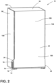
- reference numeral 10 generally designates an appliance.
- the appliance 10 includes a base 14 and a wrapper 18 coupled to the base 14.
- the wrapper 18 has a rear planar surface 22 and a curved surface 26.
- a machine compartment 30 is defined by the base 14 and the curved surface 26 of the wrapper 18.
- An attachment feature 34 is operably coupled to the curved surface 26 of the wrapper 18.
- a side access panel 38 is operably coupled to the attachment feature 34.
- the side access panel 38 includes a brim 42 that extends toward the machine compartment 30 and a base edge 46 proximate to the base 14.
- the side access panel 38 also includes an arcuate portion 50 that defines apertures 54.
- the arcuate portion 50 is operably coupled to the attachment feature 34.
- a central body 58 of the side access panel 38 has an interior surface 62 and an exterior surface 66.
- the interior surface 62 defines support ribs 70.
- a controller 74 is operably coupled to the interior surface 62 of the side access panel 38.
- the appliance 10 is illustrated as a refrigerating appliance, but it is also contemplated that the side access panel 38 described herein may be used with a variety of appliances.
- the appliance 10 is illustrated as a French door style refrigerator with a bottom-mounted drawer 80.
- the appliance 10 includes first and second doors 82, 86 hingedly coupled to a body 88 of the appliance 10.
- the term body 88 may include similar features as the wrapper 18, such as the rear planar surface 22 and the curved surface 26.
- the body 88 can be defined by a cabinet 90 which is covered by an outer casing 94, which includes first and second side panels 98, 102, a rear panel 106, and a top panel 110.
- Each panel 98, 102, 106, 110 may be formed from a metallic material, plastic material, or other materials typically used to form the outer casing 94 of an appliance 10.
- the outer casing 94 covers an insulated structure 114, which includes the wrapper 18 and a liner 118 to which the wrapper 18 is coupled.
- the insulated structure 114 is defined by the liner 118 and the wrapper 18.
- the liner 118 and the wrapper 18 are typically coupled to a trim breaker 122 to define an insulating cavity 126 therebetween in which
- one or more insulation materials 130 may be disposed. It is generally contemplated that the insulation materials 130 may be a glass type material, a carbon-based powder, silicone oxide-based materials, insulating gases, and other standard insulation materials 130 known in the art.
- the insulation materials 130 substantially fill the insulating cavity 126 to form a substantially continuous layer between the liner 118 and the wrapper 18.
- the insulating cavity 126 is evacuated by a vacuum to further define the insulated structure 114 as a vacuum insulated structure 114.
- the wrapper 18 and the liner 118 may be formed from metals, polymers, metal alloys, combinations thereof, and other substantially rigid materials that can be used for vacuum insulated structures within appliances. As illustrated, holes 140 are defined by the wrapper 18 and the liner 118 to allow electrical wiring and other typical appliance lines to pass through the holes 140.
- the wrapper 18 is described in detail; however, the liner 118 can be similarly constructed insofar as the liner 118 and the wrapper 18 generally have a similar shape to form the insulated structure 114.
- the wrapper 18 defines top and bottom surfaces 142, 146, the rear planar surface 22, and the curved surface 26 as well as first and second sidewalls 150, 154 of the appliance cabinet 90.
- the rear planar surface 22 corresponds to a rear wall 156 of the appliance cabinet 90.
- the curved surface 26 and a lower portion 158 of the rear panel 106 at least partially define the machine compartment 30, such that machine components can be positioned beneath the rear planar surface 22 and curved surface 26 of the wrapper 18 within the machine compartment 30.
- the insulated structure 114, and consequently the wrapper 18, is concealed by the outer casing 94 of the appliance 10. Accordingly, the rear planar surface 22 of the wrapper 18 generally corresponds to the rear panel 106 of the appliance cabinet 90.
- the wrapper 18 is positioned on and coupled to the base 14 to structurally support the appliance 10 ( FIG. 1 ).
- the outer casing 94 ( FIG. 1 ) of the appliance 10 ( FIG. 1 ) is typically coupled to the base 14 to cover the insulated structure 114.
- the base 14 may be formed from metal, plastic, or other materials known to provide structural, base support for the appliance 10 ( FIG. 1 ).
- the base 14 may be a single piece of material extending across the bottom surface 146 of the wrapper 18. Additionally or alternatively, the base 14 may be rails positioned proximate to the first and second sidewalls 150, 154 of the appliance cabinet 90 and coupled to the bottom surface 146 of the wrapper 18.
- the base 14 at least partially extends beyond the curved surface 26 of the wrapper 18 to lie substantially perpendicular with the rear planar surface 22 of the wrapper 18.
- the machine compartment 30 is further defined by the base 14.
- the base 14 includes a first rail 162a and a second rail 162b, which may be collectively referred to as base rails 162.
- a forward portion 166 of the base rails 162 includes a coupling extension 170 configured to couple to the outer casing 94 ( FIG. 1 ) of the cabinet 90 to cover the insulated structure 114.
- the rear portions 174 of the base rails 162 are generally disposed beneath the curved surface 26 of the wrapper 18, such that the rear portions 174 of the base rails 162 further define the machine compartment 30.
- a support plate 182 configured to support the machine components within the machine compartment 30 can be positioned over and coupled to the rear portion 174 of the base rails 162 to define a gap 186 therebetween.
- the gap 186 may provide passage for electrical wiring.
- the controller 74 is positioned within the machine compartment 30 and may contain electrical wiring that may extend through the gap 186 beneath the wrapper 18. Additionally or alternatively, when the appliance 10 is a refrigerator and/or freezer, water lines connected to the appliance 10 may pass through the gap 186 defined by the base rails 162 and the support plate 182.
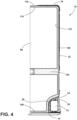
- a lip 190 of the support plate 182 extends upwardly toward the rear planar surface 22 of the wrapper 18, such that the lip 190 and the rear panel 106 of the outer casing 94 at least partially enclose the machine compartment 30.
- the at least partial closure of the machine compartment 30 by the lip 190 and the rear panel 106 ( FIG. 2 ) of the outer casing 94 ( FIG. 2 ) minimizes access to the machine components within the machine compartment 30.
- the machine compartment 30 is entirely covered by the rear panel 106 ( FIG. 2 ) and the lip 190. Accordingly, servicing of the machine components in conventional appliances results in the removal of the rear panel 106 ( FIG.
- the side access panel 38 is removably coupled to the appliance 10 at the attachment feature 34 to provide access into the machine compartment 30, discussed in further detail below.
- the attachment feature 34 is configured to removably couple the side access panel 38 to the curved surface 26, such that as the attachment feature 34 extends along the curved surface 26 of the wrapper 18 as does the side access panel 38.
- the curved surface 26 of the wrapper 18 defines projections 200 that outwardly extend toward the machine compartment 30.
- the attachment feature 34 is coupled to the wrapper 18 at the curved surface 26 by coupling features 202 which couple to the projections 200 defined by the curved surface 26.
- the coupling features 202 of the attachment feature 34 may snap-fit with the projections 200 so the attachment feature 34 may be removed from the curved surface 26.
- the attachment feature 34 may also be removed to provide additional access into the machine compartment 30. Additionally or alternatively, the attachment feature 34 may be welded to the wrapper 18 so that, while the side access panel 38 is removable, the attachment features 34 are securely coupled to the wrapper 18. In general, the attachment features 34 extend along and are disposed upon a peripheral edge 206 of the curved surface 26, such that the attachment feature 34 is operably coupled to the edge 206 of the curved surface 26.
- the attachment feature 34 is a bracket 210 that extends along the peripheral edge 206 of the curved surface 26. It is generally contemplated that the bracket 210 at least partially defines a substantially similar shape as the curved surface 26 of the wrapper 18, such that the bracket 210 has a generally arched shape that follows the curvature of the curved surface 26.
- the side access panel 38 is coupled to the attachment feature 34 at the arcuate portion 50 of the side access panel 38. The remainder of the side access panel 38 is coupled to the base 14 of the appliance 10.
- the side access panel 38 may be removed from the attachment feature 34 and the base 14 to provide selective access into the machine compartment 30.
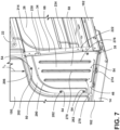
- the attachment feature 34 includes retention slots 214 defined along a perimeter 218 of the attachment feature 34, discussed in further detail below.
- the attachment feature 34 defines a frame 222 that extends along the curved surface 26 of the wrapper 18 and is adjacent to the lip 190 of the support plate 182 to generally define a D-frame construction. It is generally contemplated that the frame 222 defines flanges 226 that extend inward toward the machine compartment 30 in which the retention slots 214 may be defined.
- the side access panel 38 has retention tabs 230 that may inwardly extend from the central body 58 toward the machine compartment 30 and removably couple to the attachment features 34 via the retention slots 214.
- the retention slots 214 may be defined in a reinforcement segment 234 of the frame 222 so the side access panel 38 may couple to the retention slots 214 defined therein.
- the retention tabs 230 of the side access panel 38 are disposed along an outer edge 236 of the side access panel 38.
- the retention tabs 230 are configured to couple to the retention slots 214 defined within the reinforcement segment 234 of the attachment feature 34.
- the brim 42 may be defined as the retention tabs 230 that extend toward the machine compartment 30 from the outer edge 236 of the side access panel 38.
- the frame 222 can at least partially provide additional structural support for the wrapper 18.
- the reinforcement segment 234 of the frame 222 lies in a similar plane as the rear planar surface 22 of the wrapper 18, such that the reinforcement segment 234 of the frame 222 at least partially supports the wrapper 18 as an extension of the rear planar surface 22.
- the frame 222 is coupled to the base 14 and may generally brace against an upper portion 238 of the curved surface 26 to further support a rear section 242 of the wrapper 18.
- supports 246 may extend from a top 250 of the frame 222 to a bottom 254 of the frame 222.
- the supports 246 may also extend from an arcuate edge 258 of the frame 222 to the reinforcement segment 234 of the frame 222 to generally define a lattice structure 262 that has vertical and horizontal supports 246a, 246b.
- the vertical supports 246a of the frame 222 may alternatively define the retention slots 214, such that the side access panel 38 may couple to the retention slots 214 defined in the vertical supports 246a.
- the side access panel 38 may be coupled to the vertical supports 246a of the frame 222 of the attachment feature 34. As illustrated in FIG.
- the vertical supports 246a define the retention slots 214 along a length L 1 of the vertical supports 246a.
- the support ribs 70 defined by the central body 58 of the side access panel 38 may project inward toward the machine compartment 30 and can be coupled to the retention slots 214 defined by the vertical supports 246a of the attachment feature 34.
- the support ribs 70 can define the retention tabs 230 that extend through the retention slots 214 to removably couple the side access panel 38 to the attachment feature 34.
- a grasping portion 274 may be defined on the exterior surface 66 of the central body 58 by defined grooves 278 that correspond with the support ribs 70 on the interior surface 62 of the central body 58.
- the grooves 278 identify the support ribs 70 so a user can grasp the grooves 278 to remove the side access panel 38 from the attachment feature 34.
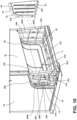
- the side access panel 38 may be coupled to the attachment feature 34 by the retention slots 214 and the retention tabs 230, the side access panel 38 may also be coupled to the attachment feature 34 via fasteners 282.
- the fasteners 282 extend through the apertures 54 defined by the side access panel 38 and coupled to the attachment feature 34 through openings 286.
- both the retention slots 214 and retention tabs 230 in addition to the fasteners 282, securely couples the side access panel 38 to the wrapper 18 while maintaining the removability of the side access panel 38 from the attachment feature 34 to provide access into the machine compartment 30.
- Additional apertures 54 may be defined by the central body 58 of the side access panel 38 so the controller 74 may be coupled to the interior surface 62 of the side access panel 38 by additional fasteners 282. Additionally or alternatively, the controller 74 may be coupled to the supports 246 of the frame 222.
- the side access panel 38 when the side access panel 38 is coupled to the attachment feature 34 via the retention tabs 230, the side access panel 38 may be easily removed from the attachment feature 34 such that the side access panel 38 provides selective access to the machine compartment 30 from the side of the appliance 10.
- the side access panel 38 Similar to the support provided by the frame 222 of the attachment feature 34, the side access panel 38 further includes an arcuate support rib 290 positioned between an edge of the arcuate portion 50 of the side access panel 38 and the central body 58.
- the arcuate support rib 290 may absorb and disperse a load L 2 that may be placed upon the side access panel 38 when coupled to the wrapper 18.
- the arcuate support rib 290 deflects a greater amount of the load L 2 placed upon the side access panel 38 from the wrapper 18 when the attachment feature 34 is in the bracket 210 ( FIG. 6 ) configuration. It is understood that while the side access panel 38 may provide load L 2 bearing support it is minimal with respect to other features described herein, such as the base 14.
- the side access panel 38 may include first and second side access panels 38a, 38b that are coupled to first and second attachment features 34a, 34b. Accordingly, the first attachment feature 34a removably couples the first side access panel 38a to the first sidewall 150, and the second attachment feature 34b removably couples the second side access panel 38b to the second sidewall 154. While described herein that the attachment feature 34 is coupled to the wrapper 18, it is also contemplated that the attachment feature 34 may be coupled to the at least one of the side panels 98, 102 of the outer casing 94.
- the curved surface 26 may be defined by the side panels 98, 102, such that the arcuate edge 258 of the attachment feature 34 is operably coupled to the curved surface 26 defined by the first and second side panels 98, 102 of the outer casing 94.
- the side access panel 38 provides selective access to machine compartment 30 through the sidewall of the appliance cabinet 90, it also provides a cost-effective way of forming the insulated structure 114, as the side access panel 38 is separate from the insulating structure 114 minimizing the overall cost of production of the appliance 10.
- the sides of the wrapper 18 extend from the top surface 142 to the bottom surface 146 to define a generally rectangular shape.
- conventional insulated structures utilize insulated materials in greater proportion than the insulated structure 114 described herein. Accordingly, by incorporating the side access panel 38, the cost of production is minimized as fewer insulation materials 130 are used in the side panels 98, 102 of the insulated structure 114. Therefore, the side access panel 38 provides both minimized cost in addition to selective access into the machine compartment 30.
Landscapes
- Engineering & Computer Science (AREA)
- Chemical & Material Sciences (AREA)
- Combustion & Propulsion (AREA)
- Physics & Mathematics (AREA)
- Mechanical Engineering (AREA)
- Thermal Sciences (AREA)
- General Engineering & Computer Science (AREA)
- Casings For Electric Apparatus (AREA)
- Refrigerator Housings (AREA)
Claims (14)
- Geräteschrank (90), umfassend:- erste und zweite Seitenwände (150, 154);- eine Rückwand (156), die zwischen der ersten und der zweiten Seitenwand (150, 154) angeordnet ist;- ein Maschinenfach (30), das durch einen unteren Abschnitt (158) der Rückwand (156) definiert ist;- ein Befestigungsmerkmal (34), das Öffnungen (286) definiert und mit mindestens einer der ersten und zweiten Seitenwände (150, 154) gekoppelt ist; und- eine seitliche Zugangsklappe (38), die selektiv mit mindestens einer der ersten und zweiten Seitenwände (150, 154) über Befestigungselemente (282) gekoppelt ist, die sich durch die Öffnungen (286) erstrecken, die durch das Befestigungsmerkmal (34) definiert sind,dadurch gekennzeichnet, dass eine Steuereinheit (74) mit einer Innenfläche (62) der seitlichen Zugangsklappe (38) gekoppelt ist.
- Geräteschrank (90) nach Anspruch 1, wobei die seitliche Zugangsklappe (38) weiter einen bogenförmigen Abschnitt (50) und einen Mittelteil (58) einschließt.
- Geräteschrank (90) nach Anspruch 2, wobei die seitliche Zugangsklappe (38) weiter eine bogenförmige Stützrippe (290) einschließt, die zwischen einer Kante des bogenförmigen Abschnitts (50) und dem Mittelteil (58) angeordnet ist.
- Geräteschrank (90) nach einem der Ansprüche 2 und 3, wobei eine Außenfläche (66) des Mittelteils (58) einen Greifabschnitt (274) der seitlichen Zugangsklappe (38) definiert.
- Geräteschrank (90) nach einem der Ansprüche 1-4, wobei das Befestigungsmerkmal (34) weiter ein erstes Befestigungsmerkmal (34a) und ein zweites Befestigungsmerkmal (34b) einschließt und wobei die seitliche Zugangsklappe (38) weiter eine erste seitliche Zugangsklappe (38a), die selektiv mit dem ersten Befestigungsmerkmal (34a) gekoppelt ist, und eine zweite seitliche Zugangsklappe (38b), die selektiv mit dem zweiten Befestigungsmerkmal (34b) gekoppelt ist, einschließt.
- Geräteschrank (90) nach Anspruch 5, wobei das erste Befestigungsmerkmal (34a) die erste seitliche Zugangsklappe (38a) lösbar mit der ersten Seitenwand (150) koppelt, und wobei das zweite Befestigungsmerkmal (34b) die zweite seitliche Zugangsklappe (38b) lösbar mit der zweiten Seitenwand (154) koppelt.
- Geräteschrank (90) nach einem der Ansprüche 1-6, wobei das Befestigungsmerkmal (34) ein Rahmen (222) ist, der eine bogenförmige Kante (258) und ein Verstärkungssegment (234) definiert, und wobei der Rahmen (222) Flansche (226) aufweist, die sich in Richtung des Maschinenfachs (30) erstrecken.
- Geräteschrank (90) nach Anspruch 7, wobei die bogenförmige Kante (258) des Befestigungsmerkmals (34) funktional mit einer gekrümmten Oberfläche (26) gekoppelt ist, die durch mindestens eine der ersten und zweiten Seitenwände (150, 154) definiert ist.
- Geräteschrank (90) nach einem der Ansprüche 7 oder 8, wobei das Befestigungsmerkmal (34) einen Halteschlitz (214) einschließt.
- Geräteschrank (90) nach Anspruch 9, wobei sich Stützen (246) von einer Oberseite (250) des Befestigungsmerkmals (34) zu einer Unterseite (254) des Befestigungsmerkmals (34) erstrecken und wobei der Halteschlitz (214 ) entlang jeder Stütze (246) definiert ist.
- Geräteschrank (90) nach Anspruch 10, wobei sich die Stützen (246) auch von der bogenförmigen Kante (258) zu dem Verstärkungssegment (234) erstrecken, um eine Gitterstruktur (262) zu definieren.
- Geräteschrank (90) nach einem der Ansprüche 7-11, wobei die seitliche Zugangsklappe (38) eine Haltelasche (230) einschließt, die lösbar mit dem Rahmen (222) gekoppelt ist, um selektiven Zugang zu dem Maschinenfach (30) bereitzustellen.
- Geräteschrank (90) nach einem der Ansprüche 8-12, weiter umfassend eine Basis (14), wobei der Rahmen (222) funktional mit der gekrümmten Oberfläche (26) und der Basis (14) gekoppelt ist.
- Geräteschrank (90) nach einem der Ansprüche 8-13, weiter umfassend Vorsprünge (200), die sich von der gekrümmten Oberfläche (26) nach außen in Richtung des Maschinenfachs (30) erstrecken, und wobei das Befestigungsmerkmal (34) Kopplungsmerkmale (202) einschließt, die sich mit den Vorsprüngen (200) koppeln.
Applications Claiming Priority (1)
| Application Number | Priority Date | Filing Date | Title |
|---|---|---|---|
| US16/729,832 US11156396B2 (en) | 2019-12-30 | 2019-12-30 | Side access panel for an appliance |
Publications (2)
| Publication Number | Publication Date |
|---|---|
| EP3845840A1 EP3845840A1 (de) | 2021-07-07 |
| EP3845840B1 true EP3845840B1 (de) | 2023-05-24 |
Family
ID=73789826
Family Applications (1)
| Application Number | Title | Priority Date | Filing Date |
|---|---|---|---|
| EP20212596.9A Active EP3845840B1 (de) | 2019-12-30 | 2020-12-08 | Seitliche zugangsplatte für ein gerät |
Country Status (3)
| Country | Link |
|---|---|
| US (4) | US11156396B2 (de) |
| EP (1) | EP3845840B1 (de) |
| CN (1) | CN113124624B (de) |
Families Citing this family (7)
| Publication number | Priority date | Publication date | Assignee | Title |
|---|---|---|---|---|
| US11156396B2 (en) | 2019-12-30 | 2021-10-26 | Whirlpool Corporation | Side access panel for an appliance |
| CN111121379A (zh) * | 2020-02-21 | 2020-05-08 | 青岛海尔电冰箱有限公司 | 冰箱 |
| TR202007983A2 (tr) * | 2020-05-22 | 2021-12-21 | Bsh Ev Aletleri San Ve Tic As | Yuva bağlanti düzeni̇ne sahi̇p bi̇r ev ci̇hazi |
| US11460235B1 (en) * | 2021-04-01 | 2022-10-04 | Whirlpool Corporation | Support assembly for an insulated structure |
| CN115247639B (zh) * | 2021-04-28 | 2026-01-09 | 青岛海尔电冰箱有限公司 | 制冷设备及制冷设备的生产方法 |
| KR20240001590A (ko) * | 2022-06-27 | 2024-01-03 | 엘지전자 주식회사 | 냉장고 |
| KR102900195B1 (ko) * | 2022-06-27 | 2025-12-15 | 엘지전자 주식회사 | 도어 업그레이드 키트 및 이를 포함하는 냉장고 |
Family Cites Families (23)
| Publication number | Priority date | Publication date | Assignee | Title |
|---|---|---|---|---|
| US2112599A (en) | 1932-07-11 | 1938-03-29 | Nash Kelvinator Corp | Refrigerating apparatus |
| US4151726A (en) * | 1978-01-09 | 1979-05-01 | Westinghouse Electric Corp. | Coil and cabinet assembly for air handler |
| JPH08200934A (ja) * | 1994-11-25 | 1996-08-09 | Sanyo Electric Co Ltd | 冷却装置 |
| US6629429B1 (en) * | 1999-03-12 | 2003-10-07 | Matsushita Refrigeration Company | Refrigerator |
| US20050213294A1 (en) * | 2004-03-25 | 2005-09-29 | Lambert Jeff A | Reconfigurable electronic device chassis and interchangeable access panels for use in same |
| JP2007017044A (ja) * | 2005-07-06 | 2007-01-25 | Matsushita Electric Ind Co Ltd | 冷蔵庫 |
| KR20090032733A (ko) | 2007-09-28 | 2009-04-01 | 엘지전자 주식회사 | 냉장고의 방열 장치 |
| CN102317722A (zh) * | 2009-02-12 | 2012-01-11 | 松下电器产业株式会社 | 冰箱 |
| DE102011004592A1 (de) * | 2011-02-23 | 2012-08-23 | BSH Bosch und Siemens Hausgeräte GmbH | Elektrisches Haushaltsgerät |
| WO2014121190A1 (en) | 2013-02-04 | 2014-08-07 | Metro Industries Inc. | Mobile refrigeration cabinet |
| JP6092719B2 (ja) | 2013-06-17 | 2017-03-08 | アクア株式会社 | 冷蔵庫 |
| KR102168586B1 (ko) | 2013-11-29 | 2020-10-22 | 삼성전자주식회사 | 냉장고 |
| KR20160086141A (ko) * | 2015-01-09 | 2016-07-19 | 엘지전자 주식회사 | 공기 조화기의 실외기 |
| US10126039B2 (en) | 2015-12-29 | 2018-11-13 | Whirlpool Corporation | Refrigeration appliance having side air intake vent with sound dampening |
| JP6448846B2 (ja) * | 2016-02-25 | 2019-01-09 | 三菱電機株式会社 | 冷蔵庫 |
| WO2018034665A1 (en) * | 2016-08-18 | 2018-02-22 | Whirlpool Corporation | Machine compartment for a vacuum insulated structure |
| WO2018164661A1 (en) | 2017-03-06 | 2018-09-13 | Whirlpool Corporation | Appliance machine compartment airflow system |
| CN207963280U (zh) * | 2017-11-27 | 2018-10-12 | 博西华电器(江苏)有限公司 | 冰箱 |
| US11185953B2 (en) * | 2017-12-15 | 2021-11-30 | Midea Group Co., Ltd. | Service panel for a cooking appliance |
| DE102018119587A1 (de) * | 2018-06-27 | 2020-01-02 | Liebherr-Hausgeräte Marica Gmbh | Kühl- und/oder Gefriergerät |
| KR102290768B1 (ko) * | 2018-11-01 | 2021-08-18 | 엘지전자 주식회사 | 냉장고 |
| CN109554898A (zh) * | 2018-12-06 | 2019-04-02 | 无锡小天鹅股份有限公司 | 顶开式滚筒洗衣机 |
| US11156396B2 (en) * | 2019-12-30 | 2021-10-26 | Whirlpool Corporation | Side access panel for an appliance |
-
2019
- 2019-12-30 US US16/729,832 patent/US11156396B2/en active Active
-
2020
- 2020-12-08 EP EP20212596.9A patent/EP3845840B1/de active Active
- 2020-12-22 CN CN202011530848.7A patent/CN113124624B/zh active Active
-
2021
- 2021-09-21 US US17/480,632 patent/US11578908B2/en active Active
-
2023
- 2023-02-13 US US18/108,930 patent/US11953258B2/en active Active
-
2024
- 2024-01-29 US US18/425,807 patent/US12264868B2/en active Active
Also Published As
| Publication number | Publication date |
|---|---|
| US11953258B2 (en) | 2024-04-09 |
| CN113124624A (zh) | 2021-07-16 |
| US20230194145A1 (en) | 2023-06-22 |
| US20220003485A1 (en) | 2022-01-06 |
| CN113124624B (zh) | 2024-09-10 |
| US11578908B2 (en) | 2023-02-14 |
| US11156396B2 (en) | 2021-10-26 |
| EP3845840A1 (de) | 2021-07-07 |
| US20210199366A1 (en) | 2021-07-01 |
| US20240167753A1 (en) | 2024-05-23 |
| US12264868B2 (en) | 2025-04-01 |
Similar Documents
| Publication | Publication Date | Title |
|---|---|---|
| EP3845840B1 (de) | Seitliche zugangsplatte für ein gerät | |
| KR20040019855A (ko) | 냉장고 | |
| EP3929509B1 (de) | Kühlschrank mit einer trennwand im maschinenraum | |
| EP4023973A1 (de) | Gesims und trennwand für einen maschinenraum | |
| JP2020051654A (ja) | 冷蔵庫および断熱仕切装置 | |
| JP2001174125A (ja) | 冷蔵庫 | |
| US4033806A (en) | Method of making refrigeration apparatus enclosure structure | |
| EP4249836B1 (de) | Kühlschrank | |
| JP2024086242A (ja) | 冷蔵庫及び冷蔵庫の製造方法 | |
| JP2003130526A (ja) | 冷蔵庫 | |
| KR100945070B1 (ko) | 전선 유도 장치 및 이를 구비한 공기조화기의 실내기 | |
| JP2003222463A (ja) | 前面扉における扉キャップ | |
| JP2006220386A (ja) | 冷蔵庫 | |
| CN217402958U (zh) | 用于制冷器具的抽屉组件和制冷器具 | |
| JP7481163B2 (ja) | 冷蔵庫 | |
| JP7550535B2 (ja) | 冷蔵庫 | |
| JP7481162B2 (ja) | 冷蔵庫 | |
| JP7576001B2 (ja) | 冷蔵庫 | |
| JP7455657B2 (ja) | 冷蔵庫 | |
| KR100534123B1 (ko) | 김치냉장고 | |
| JP2019007652A (ja) | 冷却貯蔵庫 | |
| JPH0448464Y2 (de) | ||
| JP2001174126A (ja) | 冷蔵庫 | |
| WO2024041798A1 (en) | A cooling device having a handle groove | |
| KR19990057127A (ko) | 냉장고 |
Legal Events
| Date | Code | Title | Description |
|---|---|---|---|
| PUAI | Public reference made under article 153(3) epc to a published international application that has entered the european phase |
Free format text: ORIGINAL CODE: 0009012 |
|
| STAA | Information on the status of an ep patent application or granted ep patent |
Free format text: STATUS: THE APPLICATION HAS BEEN PUBLISHED |
|
| AK | Designated contracting states |
Kind code of ref document: A1 Designated state(s): AL AT BE BG CH CY CZ DE DK EE ES FI FR GB GR HR HU IE IS IT LI LT LU LV MC MK MT NL NO PL PT RO RS SE SI SK SM TR |
|
| STAA | Information on the status of an ep patent application or granted ep patent |
Free format text: STATUS: REQUEST FOR EXAMINATION WAS MADE |
|
| 17P | Request for examination filed |
Effective date: 20220107 |
|
| RBV | Designated contracting states (corrected) |
Designated state(s): AL AT BE BG CH CY CZ DE DK EE ES FI FR GB GR HR HU IE IS IT LI LT LU LV MC MK MT NL NO PL PT RO RS SE SI SK SM TR |
|
| GRAP | Despatch of communication of intention to grant a patent |
Free format text: ORIGINAL CODE: EPIDOSNIGR1 |
|
| STAA | Information on the status of an ep patent application or granted ep patent |
Free format text: STATUS: GRANT OF PATENT IS INTENDED |
|
| INTG | Intention to grant announced |
Effective date: 20230221 |
|
| GRAS | Grant fee paid |
Free format text: ORIGINAL CODE: EPIDOSNIGR3 |
|
| GRAA | (expected) grant |
Free format text: ORIGINAL CODE: 0009210 |
|
| STAA | Information on the status of an ep patent application or granted ep patent |
Free format text: STATUS: THE PATENT HAS BEEN GRANTED |
|
| AK | Designated contracting states |
Kind code of ref document: B1 Designated state(s): AL AT BE BG CH CY CZ DE DK EE ES FI FR GB GR HR HU IE IS IT LI LT LU LV MC MK MT NL NO PL PT RO RS SE SI SK SM TR |
|
| REG | Reference to a national code |
Ref country code: GB Ref legal event code: FG4D |
|
| REG | Reference to a national code |
Ref country code: CH Ref legal event code: EP |
|
| REG | Reference to a national code |
Ref country code: DE Ref legal event code: R096 Ref document number: 602020011077 Country of ref document: DE |
|
| REG | Reference to a national code |
Ref country code: AT Ref legal event code: REF Ref document number: 1569728 Country of ref document: AT Kind code of ref document: T Effective date: 20230615 |
|
| REG | Reference to a national code |
Ref country code: IE Ref legal event code: FG4D |
|
| P01 | Opt-out of the competence of the unified patent court (upc) registered |
Effective date: 20230530 |
|
| REG | Reference to a national code |
Ref country code: LT Ref legal event code: MG9D |
|
| REG | Reference to a national code |
Ref country code: NL Ref legal event code: MP Effective date: 20230524 |
|
| REG | Reference to a national code |
Ref country code: AT Ref legal event code: MK05 Ref document number: 1569728 Country of ref document: AT Kind code of ref document: T Effective date: 20230524 |
|
| PG25 | Lapsed in a contracting state [announced via postgrant information from national office to epo] |
Ref country code: SE Free format text: LAPSE BECAUSE OF FAILURE TO SUBMIT A TRANSLATION OF THE DESCRIPTION OR TO PAY THE FEE WITHIN THE PRESCRIBED TIME-LIMIT Effective date: 20230524 Ref country code: PT Free format text: LAPSE BECAUSE OF FAILURE TO SUBMIT A TRANSLATION OF THE DESCRIPTION OR TO PAY THE FEE WITHIN THE PRESCRIBED TIME-LIMIT Effective date: 20230925 Ref country code: NO Free format text: LAPSE BECAUSE OF FAILURE TO SUBMIT A TRANSLATION OF THE DESCRIPTION OR TO PAY THE FEE WITHIN THE PRESCRIBED TIME-LIMIT Effective date: 20230824 Ref country code: NL Free format text: LAPSE BECAUSE OF FAILURE TO SUBMIT A TRANSLATION OF THE DESCRIPTION OR TO PAY THE FEE WITHIN THE PRESCRIBED TIME-LIMIT Effective date: 20230524 Ref country code: ES Free format text: LAPSE BECAUSE OF FAILURE TO SUBMIT A TRANSLATION OF THE DESCRIPTION OR TO PAY THE FEE WITHIN THE PRESCRIBED TIME-LIMIT Effective date: 20230524 Ref country code: AT Free format text: LAPSE BECAUSE OF FAILURE TO SUBMIT A TRANSLATION OF THE DESCRIPTION OR TO PAY THE FEE WITHIN THE PRESCRIBED TIME-LIMIT Effective date: 20230524 |
|
| PG25 | Lapsed in a contracting state [announced via postgrant information from national office to epo] |
Ref country code: RS Free format text: LAPSE BECAUSE OF FAILURE TO SUBMIT A TRANSLATION OF THE DESCRIPTION OR TO PAY THE FEE WITHIN THE PRESCRIBED TIME-LIMIT Effective date: 20230524 Ref country code: PL Free format text: LAPSE BECAUSE OF FAILURE TO SUBMIT A TRANSLATION OF THE DESCRIPTION OR TO PAY THE FEE WITHIN THE PRESCRIBED TIME-LIMIT Effective date: 20230524 Ref country code: LV Free format text: LAPSE BECAUSE OF FAILURE TO SUBMIT A TRANSLATION OF THE DESCRIPTION OR TO PAY THE FEE WITHIN THE PRESCRIBED TIME-LIMIT Effective date: 20230524 Ref country code: LT Free format text: LAPSE BECAUSE OF FAILURE TO SUBMIT A TRANSLATION OF THE DESCRIPTION OR TO PAY THE FEE WITHIN THE PRESCRIBED TIME-LIMIT Effective date: 20230524 Ref country code: IS Free format text: LAPSE BECAUSE OF FAILURE TO SUBMIT A TRANSLATION OF THE DESCRIPTION OR TO PAY THE FEE WITHIN THE PRESCRIBED TIME-LIMIT Effective date: 20230924 Ref country code: HR Free format text: LAPSE BECAUSE OF FAILURE TO SUBMIT A TRANSLATION OF THE DESCRIPTION OR TO PAY THE FEE WITHIN THE PRESCRIBED TIME-LIMIT Effective date: 20230524 Ref country code: GR Free format text: LAPSE BECAUSE OF FAILURE TO SUBMIT A TRANSLATION OF THE DESCRIPTION OR TO PAY THE FEE WITHIN THE PRESCRIBED TIME-LIMIT Effective date: 20230825 |
|
| PG25 | Lapsed in a contracting state [announced via postgrant information from national office to epo] |
Ref country code: FI Free format text: LAPSE BECAUSE OF FAILURE TO SUBMIT A TRANSLATION OF THE DESCRIPTION OR TO PAY THE FEE WITHIN THE PRESCRIBED TIME-LIMIT Effective date: 20230524 |
|
| PG25 | Lapsed in a contracting state [announced via postgrant information from national office to epo] |
Ref country code: SK Free format text: LAPSE BECAUSE OF FAILURE TO SUBMIT A TRANSLATION OF THE DESCRIPTION OR TO PAY THE FEE WITHIN THE PRESCRIBED TIME-LIMIT Effective date: 20230524 |
|
| PG25 | Lapsed in a contracting state [announced via postgrant information from national office to epo] |
Ref country code: SM Free format text: LAPSE BECAUSE OF FAILURE TO SUBMIT A TRANSLATION OF THE DESCRIPTION OR TO PAY THE FEE WITHIN THE PRESCRIBED TIME-LIMIT Effective date: 20230524 Ref country code: SK Free format text: LAPSE BECAUSE OF FAILURE TO SUBMIT A TRANSLATION OF THE DESCRIPTION OR TO PAY THE FEE WITHIN THE PRESCRIBED TIME-LIMIT Effective date: 20230524 Ref country code: RO Free format text: LAPSE BECAUSE OF FAILURE TO SUBMIT A TRANSLATION OF THE DESCRIPTION OR TO PAY THE FEE WITHIN THE PRESCRIBED TIME-LIMIT Effective date: 20230524 Ref country code: EE Free format text: LAPSE BECAUSE OF FAILURE TO SUBMIT A TRANSLATION OF THE DESCRIPTION OR TO PAY THE FEE WITHIN THE PRESCRIBED TIME-LIMIT Effective date: 20230524 Ref country code: DK Free format text: LAPSE BECAUSE OF FAILURE TO SUBMIT A TRANSLATION OF THE DESCRIPTION OR TO PAY THE FEE WITHIN THE PRESCRIBED TIME-LIMIT Effective date: 20230524 Ref country code: CZ Free format text: LAPSE BECAUSE OF FAILURE TO SUBMIT A TRANSLATION OF THE DESCRIPTION OR TO PAY THE FEE WITHIN THE PRESCRIBED TIME-LIMIT Effective date: 20230524 |
|
| REG | Reference to a national code |
Ref country code: DE Ref legal event code: R097 Ref document number: 602020011077 Country of ref document: DE |
|
| PLBE | No opposition filed within time limit |
Free format text: ORIGINAL CODE: 0009261 |
|
| STAA | Information on the status of an ep patent application or granted ep patent |
Free format text: STATUS: NO OPPOSITION FILED WITHIN TIME LIMIT |
|
| 26N | No opposition filed |
Effective date: 20240227 |
|
| PG25 | Lapsed in a contracting state [announced via postgrant information from national office to epo] |
Ref country code: SI Free format text: LAPSE BECAUSE OF FAILURE TO SUBMIT A TRANSLATION OF THE DESCRIPTION OR TO PAY THE FEE WITHIN THE PRESCRIBED TIME-LIMIT Effective date: 20230524 |
|
| PG25 | Lapsed in a contracting state [announced via postgrant information from national office to epo] |
Ref country code: SI Free format text: LAPSE BECAUSE OF FAILURE TO SUBMIT A TRANSLATION OF THE DESCRIPTION OR TO PAY THE FEE WITHIN THE PRESCRIBED TIME-LIMIT Effective date: 20230524 |
|
| PGFP | Annual fee paid to national office [announced via postgrant information from national office to epo] |
Ref country code: IT Payment date: 20240102 Year of fee payment: 4 |
|
| REG | Reference to a national code |
Ref country code: CH Ref legal event code: PL |
|
| PG25 | Lapsed in a contracting state [announced via postgrant information from national office to epo] |
Ref country code: LU Free format text: LAPSE BECAUSE OF NON-PAYMENT OF DUE FEES Effective date: 20231208 |
|
| PG25 | Lapsed in a contracting state [announced via postgrant information from national office to epo] |
Ref country code: MC Free format text: LAPSE BECAUSE OF FAILURE TO SUBMIT A TRANSLATION OF THE DESCRIPTION OR TO PAY THE FEE WITHIN THE PRESCRIBED TIME-LIMIT Effective date: 20230524 |
|
| REG | Reference to a national code |
Ref country code: BE Ref legal event code: MM Effective date: 20231231 |
|
| PG25 | Lapsed in a contracting state [announced via postgrant information from national office to epo] |
Ref country code: MC Free format text: LAPSE BECAUSE OF FAILURE TO SUBMIT A TRANSLATION OF THE DESCRIPTION OR TO PAY THE FEE WITHIN THE PRESCRIBED TIME-LIMIT Effective date: 20230524 Ref country code: LU Free format text: LAPSE BECAUSE OF NON-PAYMENT OF DUE FEES Effective date: 20231208 |
|
| REG | Reference to a national code |
Ref country code: IE Ref legal event code: MM4A |
|
| PG25 | Lapsed in a contracting state [announced via postgrant information from national office to epo] |
Ref country code: IE Free format text: LAPSE BECAUSE OF NON-PAYMENT OF DUE FEES Effective date: 20231208 |
|
| PG25 | Lapsed in a contracting state [announced via postgrant information from national office to epo] |
Ref country code: BE Free format text: LAPSE BECAUSE OF NON-PAYMENT OF DUE FEES Effective date: 20231231 |
|
| PG25 | Lapsed in a contracting state [announced via postgrant information from national office to epo] |
Ref country code: CH Free format text: LAPSE BECAUSE OF NON-PAYMENT OF DUE FEES Effective date: 20231231 |
|
| PG25 | Lapsed in a contracting state [announced via postgrant information from national office to epo] |
Ref country code: IE Free format text: LAPSE BECAUSE OF NON-PAYMENT OF DUE FEES Effective date: 20231208 Ref country code: CH Free format text: LAPSE BECAUSE OF NON-PAYMENT OF DUE FEES Effective date: 20231231 Ref country code: BE Free format text: LAPSE BECAUSE OF NON-PAYMENT OF DUE FEES Effective date: 20231231 |
|
| PG25 | Lapsed in a contracting state [announced via postgrant information from national office to epo] |
Ref country code: BG Free format text: LAPSE BECAUSE OF FAILURE TO SUBMIT A TRANSLATION OF THE DESCRIPTION OR TO PAY THE FEE WITHIN THE PRESCRIBED TIME-LIMIT Effective date: 20230524 |
|
| PG25 | Lapsed in a contracting state [announced via postgrant information from national office to epo] |
Ref country code: BG Free format text: LAPSE BECAUSE OF FAILURE TO SUBMIT A TRANSLATION OF THE DESCRIPTION OR TO PAY THE FEE WITHIN THE PRESCRIBED TIME-LIMIT Effective date: 20230524 |
|
| PGFP | Annual fee paid to national office [announced via postgrant information from national office to epo] |
Ref country code: GB Payment date: 20241217 Year of fee payment: 5 |
|
| PGFP | Annual fee paid to national office [announced via postgrant information from national office to epo] |
Ref country code: FR Payment date: 20241227 Year of fee payment: 5 |
|
| PGFP | Annual fee paid to national office [announced via postgrant information from national office to epo] |
Ref country code: DE Payment date: 20241227 Year of fee payment: 5 |
|
| PG25 | Lapsed in a contracting state [announced via postgrant information from national office to epo] |
Ref country code: CY Free format text: LAPSE BECAUSE OF FAILURE TO SUBMIT A TRANSLATION OF THE DESCRIPTION OR TO PAY THE FEE WITHIN THE PRESCRIBED TIME-LIMIT; INVALID AB INITIO Effective date: 20201208 |
|
| PG25 | Lapsed in a contracting state [announced via postgrant information from national office to epo] |
Ref country code: HU Free format text: LAPSE BECAUSE OF FAILURE TO SUBMIT A TRANSLATION OF THE DESCRIPTION OR TO PAY THE FEE WITHIN THE PRESCRIBED TIME-LIMIT; INVALID AB INITIO Effective date: 20201208 |
|
| PG25 | Lapsed in a contracting state [announced via postgrant information from national office to epo] |
Ref country code: IT Free format text: LAPSE BECAUSE OF NON-PAYMENT OF DUE FEES Effective date: 20241208 |
|
| PG25 | Lapsed in a contracting state [announced via postgrant information from national office to epo] |
Ref country code: TR Free format text: LAPSE BECAUSE OF FAILURE TO SUBMIT A TRANSLATION OF THE DESCRIPTION OR TO PAY THE FEE WITHIN THE PRESCRIBED TIME-LIMIT Effective date: 20230524 |