EP3845739B1 - Auswuchtungssystem und verfahren für einen motor eines flugzeugs - Google Patents
Auswuchtungssystem und verfahren für einen motor eines flugzeugs Download PDFInfo
- Publication number
- EP3845739B1 EP3845739B1 EP20203568.9A EP20203568A EP3845739B1 EP 3845739 B1 EP3845739 B1 EP 3845739B1 EP 20203568 A EP20203568 A EP 20203568A EP 3845739 B1 EP3845739 B1 EP 3845739B1
- Authority
- EP
- European Patent Office
- Prior art keywords
- fan blades
- electromagnets
- engine
- housing
- balancing
- Prior art date
- Legal status (The legal status is an assumption and is not a legal conclusion. Google has not performed a legal analysis and makes no representation as to the accuracy of the status listed.)
- Active
Links
Images

Classifications
-
- F—MECHANICAL ENGINEERING; LIGHTING; HEATING; WEAPONS; BLASTING
- F01—MACHINES OR ENGINES IN GENERAL; ENGINE PLANTS IN GENERAL; STEAM ENGINES
- F01D—NON-POSITIVE DISPLACEMENT MACHINES OR ENGINES, e.g. STEAM TURBINES
- F01D5/00—Blades; Blade-carrying members; Heating, heat-insulating, cooling or antivibration means on the blades or the members
- F01D5/12—Blades
- F01D5/26—Antivibration means not restricted to blade form or construction or to blade-to-blade connections or to the use of particular materials
-
- F—MECHANICAL ENGINEERING; LIGHTING; HEATING; WEAPONS; BLASTING
- F01—MACHINES OR ENGINES IN GENERAL; ENGINE PLANTS IN GENERAL; STEAM ENGINES
- F01D—NON-POSITIVE DISPLACEMENT MACHINES OR ENGINES, e.g. STEAM TURBINES
- F01D5/00—Blades; Blade-carrying members; Heating, heat-insulating, cooling or antivibration means on the blades or the members
- F01D5/02—Blade-carrying members, e.g. rotors
- F01D5/027—Arrangements for balancing
-
- F—MECHANICAL ENGINEERING; LIGHTING; HEATING; WEAPONS; BLASTING
- F02—COMBUSTION ENGINES; HOT-GAS OR COMBUSTION-PRODUCT ENGINE PLANTS
- F02C—GAS-TURBINE PLANTS; AIR INTAKES FOR JET-PROPULSION PLANTS; CONTROLLING FUEL SUPPLY IN AIR-BREATHING JET-PROPULSION PLANTS
- F02C3/00—Gas-turbine plants characterised by the use of combustion products as the working fluid
- F02C3/04—Gas-turbine plants characterised by the use of combustion products as the working fluid having a turbine driving a compressor
-
- B—PERFORMING OPERATIONS; TRANSPORTING
- B64—AIRCRAFT; AVIATION; COSMONAUTICS
- B64D—EQUIPMENT FOR FITTING IN OR TO AIRCRAFT; FLIGHT SUITS; PARACHUTES; ARRANGEMENT OR MOUNTING OF POWER PLANTS OR PROPULSION TRANSMISSIONS IN AIRCRAFT
- B64D27/00—Arrangement or mounting of power plants in aircraft; Aircraft characterised by the type or position of power plants
- B64D27/02—Aircraft characterised by the type or position of power plants
-
- B—PERFORMING OPERATIONS; TRANSPORTING
- B64—AIRCRAFT; AVIATION; COSMONAUTICS
- B64D—EQUIPMENT FOR FITTING IN OR TO AIRCRAFT; FLIGHT SUITS; PARACHUTES; ARRANGEMENT OR MOUNTING OF POWER PLANTS OR PROPULSION TRANSMISSIONS IN AIRCRAFT
- B64D31/00—Power plant control systems; Arrangement of power plant control systems in aircraft
-
- F—MECHANICAL ENGINEERING; LIGHTING; HEATING; WEAPONS; BLASTING
- F01—MACHINES OR ENGINES IN GENERAL; ENGINE PLANTS IN GENERAL; STEAM ENGINES
- F01D—NON-POSITIVE DISPLACEMENT MACHINES OR ENGINES, e.g. STEAM TURBINES
- F01D21/00—Shutting-down of machines or engines, e.g. in emergency; Regulating, controlling, or safety means not otherwise provided for
- F01D21/003—Arrangements for testing or measuring
-
- F—MECHANICAL ENGINEERING; LIGHTING; HEATING; WEAPONS; BLASTING
- F01—MACHINES OR ENGINES IN GENERAL; ENGINE PLANTS IN GENERAL; STEAM ENGINES
- F01D—NON-POSITIVE DISPLACEMENT MACHINES OR ENGINES, e.g. STEAM TURBINES
- F01D21/00—Shutting-down of machines or engines, e.g. in emergency; Regulating, controlling, or safety means not otherwise provided for
- F01D21/04—Shutting-down of machines or engines, e.g. in emergency; Regulating, controlling, or safety means not otherwise provided for responsive to undesired position of rotor relative to stator or to breaking-off of a part of the rotor, e.g. indicating such position
- F01D21/045—Shutting-down of machines or engines, e.g. in emergency; Regulating, controlling, or safety means not otherwise provided for responsive to undesired position of rotor relative to stator or to breaking-off of a part of the rotor, e.g. indicating such position special arrangements in stators or in rotors dealing with breaking-off of part of rotor
-
- F—MECHANICAL ENGINEERING; LIGHTING; HEATING; WEAPONS; BLASTING
- F01—MACHINES OR ENGINES IN GENERAL; ENGINE PLANTS IN GENERAL; STEAM ENGINES
- F01D—NON-POSITIVE DISPLACEMENT MACHINES OR ENGINES, e.g. STEAM TURBINES
- F01D25/00—Component parts, details, or accessories, not provided for in, or of interest apart from, other groups
- F01D25/04—Antivibration arrangements
- F01D25/06—Antivibration arrangements for preventing blade vibration
-
- F—MECHANICAL ENGINEERING; LIGHTING; HEATING; WEAPONS; BLASTING
- F02—COMBUSTION ENGINES; HOT-GAS OR COMBUSTION-PRODUCT ENGINE PLANTS
- F02C—GAS-TURBINE PLANTS; AIR INTAKES FOR JET-PROPULSION PLANTS; CONTROLLING FUEL SUPPLY IN AIR-BREATHING JET-PROPULSION PLANTS
- F02C7/00—Features, components parts, details or accessories, not provided for in, or of interest apart form groups F02C1/00 - F02C6/00; Air intakes for jet-propulsion plants
-
- F—MECHANICAL ENGINEERING; LIGHTING; HEATING; WEAPONS; BLASTING
- F05—INDEXING SCHEMES RELATING TO ENGINES OR PUMPS IN VARIOUS SUBCLASSES OF CLASSES F01-F04
- F05D—INDEXING SCHEME FOR ASPECTS RELATING TO NON-POSITIVE-DISPLACEMENT MACHINES OR ENGINES, GAS-TURBINES OR JET-PROPULSION PLANTS
- F05D2220/00—Application
- F05D2220/30—Application in turbines
- F05D2220/36—Application in turbines specially adapted for the fan of turbofan engines
-
- F—MECHANICAL ENGINEERING; LIGHTING; HEATING; WEAPONS; BLASTING
- F05—INDEXING SCHEMES RELATING TO ENGINES OR PUMPS IN VARIOUS SUBCLASSES OF CLASSES F01-F04
- F05D—INDEXING SCHEME FOR ASPECTS RELATING TO NON-POSITIVE-DISPLACEMENT MACHINES OR ENGINES, GAS-TURBINES OR JET-PROPULSION PLANTS
- F05D2240/00—Components
- F05D2240/20—Rotors
- F05D2240/24—Rotors for turbines
- F05D2240/242—Rotors for turbines of reaction type
-
- Y—GENERAL TAGGING OF NEW TECHNOLOGICAL DEVELOPMENTS; GENERAL TAGGING OF CROSS-SECTIONAL TECHNOLOGIES SPANNING OVER SEVERAL SECTIONS OF THE IPC; TECHNICAL SUBJECTS COVERED BY FORMER USPC CROSS-REFERENCE ART COLLECTIONS [XRACs] AND DIGESTS
- Y02—TECHNOLOGIES OR APPLICATIONS FOR MITIGATION OR ADAPTATION AGAINST CLIMATE CHANGE
- Y02T—CLIMATE CHANGE MITIGATION TECHNOLOGIES RELATED TO TRANSPORTATION
- Y02T50/00—Aeronautics or air transport
- Y02T50/60—Efficient propulsion technologies, e.g. for aircraft
Definitions
- Embodiments of the present disclosure generally relate to systems and methods for mitigating engine imbalance, such as within an engine of an aircraft.
- Various aircraft include propulsion systems, such as two or more engines.
- the engines are turbofan engines that include a plurality of fan blades coupled to an engine core.
- the engines typically include gas turbine engine fan blade containment (GTEFBC) systems.
- GTEFBC gas turbine engine fan blade containment
- a fan blade may dislodge or otherwise break (that is, a fan blade out event).
- a GTEFBC system prevents a portion of the fan blade from being ejected through the fan casing of the engine.
- the engine may become imbalanced.
- a fragmented portion of a fan blade may cause a mass imbalance within the engine, as the mass of the fragmented portion may no longer be present within the engine, and/or may not be located where intended.
- the engine may oscillate or vibrate due to the mass imbalance.
- the oscillation or vibration of the engine may, in turn, be translated to other portions of the aircraft, such as a wing to which the engine is secured.
- a controllable magneto-rheological device includes an annular cylinder formed by inner and outer walls connected at first and second opposing ends and forming an inner shaft configured to receive an operational component of an engine, generator or other device including one or more rotating structures.
- a magneto-rheological fluid is provided to fill a volume between the inner and outer walls of the annular cylinder.
- a plurality of electro-magnetic coils are positioned around the outer wall of the annular cylinder.
- One or more current controllers are coupled to the plurality of electro-magnetic coils for introducing a current through each of the electro-magnetic coils and corresponding magnetic flux through the magneto-rheological fluid.
- a level of current provided to each of the plurality of electro-magnetic coils directly affects the viscosity of the magneto-rheological fluid and tints the stiffness and damping levels of the controllable magneto-rheological device.
- a balancing system for an engine of an aircraft, the balancing system comprising a housing retaining a magnetorheological fluid including magnetic particles within a carrier fluid; electromagnets coupled to the housing, wherein the electromagnets are associated with fan blades of the engine, wherein the housing is configured to rotate at the same angular velocity as the fan blades so that a radial alignment between the fan blades and the electromagnets is maintained; and a balancing control unit in communication with the electromagnets and sensors of the fan blades, wherein the balancing control unit is configured to receive presence signals from the sensors of the fan blades, maintain the electromagnets in deactivated states when the presence signals from the sensors of all the fan blades are detected, and activate one or more of the electromagnets when one or more of the presence signals are not detected, wherein the one or more electromagnets that are activated attract the magnetic particles to compensate for missing mass of at least one of the fan blades, thereby maintaining balance of mass within the engine.
- a balancing method for an engine of an aircraft comprising retaining, within a housing, a magnetorheological fluid including magnetic particles within a carrier fluid; coupling electromagnets to the housing; associating the electromagnets with fan blades of the engine; and communicatively coupling a balancing control unit with the electromagnets and sensors of the fan blades; the method further comprising receiving, by the balancing control unit, presence signals from the sensors of the fan blades; maintaining the electromagnets in deactivated states when the presence signals from the sensors of all the fan blades are detected; activating one or more of the electromagnets when one or more of the presence signals are not detected; and attracting, by the one or more electromagnets that are activated, the magnetic particles to compensate for missing mass of at least one of the fan blades thereby maintaining balance of mass within the engine; the method further comprising wherein the housing is configured to rotate at the same angular velocity as the fan blades so that a radi
- Certain embodiments of the present disclosure provide a balancing system for an engine of an aircraft.
- the balancing system is configured to compensate for an engine imbalance that occurs when a fan blade out event occurs.
- the balancing system includes a housing, such as formed as a torus that contains a magnetorheological fluid.
- a fan blade out event occurs, an electromagnet proximate the missing fan blade is activated (such as through electrical activation), thereby causing magnetic particles within the fluid to be drawn to the radial location of the missing fan blade.
- Certain embodiments of the present disclosure provide a system for mitigating an engine imbalance.
- the system includes a housing formed as a torus that retains a magnetorheological fluid.
- a plurality of electromagnets are coupled to an external surface of the housing.
- a balancing control unit is in communication with the electromagnets.
- the balancing control unit is configured to identify a fan blade out event (such as via sensors coupled to the fan blades), and activate at least one of the electromagnets disposed adjacent to the identified blade out event, thereby attracting magnetic particles within the fluid to compensate for the mass of the missing fan blade.
- the engine includes a fan.
- Rotation of the housing of the proposed device is coupled to rotation of the fan.
- the fan and the housing are configured to rotate at the same rotational speed.
- the fan includes n blades and the housing include n electromagnets that correspond to the n blades.
- a mass of the magnetic particles within the magnetorheological fluid is equal to a mass of a single fan blade.
- the system also includes a plurality of sensors.
- Each fan blade includes at least one of the plurality of sensors.
- the balancing control unit is configured to receive an input from each of the plurality of sensors, and identify the fan blade out event based upon the received inputs.
- a shaft is coupled between the engine and the housing.
- the shaft is configured to rotate the housing at the same rotational speed as the engine.
- the system includes a motor that rotates the housing at the same rotational speed as the engine fan. The viscosity of the magnetorheological fluid inside the device housing assures that the magnetic particles rotate inside the housing at the same radial velocity as the fan blades.
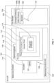
- FIG. 1 is a schematic block diagram of a balancing system 100 for an engine 102 of an aircraft 104, according to an embodiment of the present disclosure.
- the aircraft 104 may include more than one engine 102.
- the engine 102 includes a plurality of fan blades 106.
- each fan 106 includes a dovetail portion 106a that is formed unitarily with an airfoil portion 106b.
- sensors 108 are coupled to the fan blades 106.
- each fan blade 106 may include a sensor 108.
- a sensor 108 may be embedded within an airfoil portion 106b of a fan blade 106.
- a sensor is 108 secured to an outer surface of an airfoil portion 106b of a fan blade 106.
- the sensor 108 is a current-sensing wire.
- the sensor 108 is a voltage-sensing wire. The sensors 108 output presence signals that indicate the presence of the fan blades within the engine 102.
- a sensor 108 of the fan blade 106 detects a current or voltage and outputs a corresponding signal that indicates the presence of the fan blade 106 within the engine 102. In the event of a fan blade out event, the sensor 108 no longer detects a current or voltage, and therefore no longer outputs a presence signal.
- the balancing system 100 includes a housing 110, which may be formed of a torus.
- the housing 110 retains a magnetorheological fluid 112.
- the magnetorheological fluid 112 includes a carrier fluid 114, such as an oil, and magnetic particles 116 within the carrier fluid 114.
- the magnetic particles 116 may be spheres, ellipsoids, or the like that are suspended within the carrier fluid 114.
- the mass of the magnetic particles 116 is equal to a mass of an airfoil portion 106b of one fan blade 106.
- the magnetic particles 116 are drawn to the location of a missing fan blade 106 (such as a missing airfoil portion 106b of the fan blade 106), thereby compensating for the lost mass of the airfoil portion 106b of the fan blade 106 and maintaining balance of mass within the engine 102.
- the mass of the magnetic particles 116 is equal to the mass of one and a half airfoil portions 106b. It has been found through testing that when one fan blade 106 fragments from the engine 102, a half of another fan blade 106 may also fragment from the engine 102. In at least one other embodiment, the mass of the magnetic particles 116 may be greater or less than one airfoil portion 106b, or one and a half airfoil portions 106.
- Electromagnets 118 are coupled to an exterior of the housing 110.
- the electromagnets 118 correspond to the number of fan blades 106 of the engine 102.
- the electromagnets 118 are configured to be selectively deactivated (such as through no electrical current flowing thereto), and activated (such as through electrical current flowing thereto).
- the electromagnets 118 are radially aligned with the fan blades 106. That is, each electromagnet 118 is radially aligned with an associated fan blade 106.
- the housing 110 is configured to rotate at the same angular velocity as the fan blades 106 so that the radial alignment between the fan blades 106 and the electromagnets 118 is maintained.
- an actuator 120 is operatively coupled to the housing 110.
- the actuator 120 is a motor or engine that rotates the housing 110 along with the engine 102 to maintain the radial alignment between the electromagnets 118 and the associated fan blades 106.
- the actuator 120 is an electric motor. It has been found that an electric motor provides a relatively light actuator as compared to mechanical linkages. As such, the electric motor may add less weight to the aircraft 104 than complex mechanical linkages, thereby increasing fuel economy of the aircraft 104.
- the actuator 120 is a linkage that mechanically links the rotation of the fan blades 106 to the rotation of the housing 110.
- the linkage may be or include a shaft that is coupled between the engine 102 and the housing 110, such as through an accessory gearbox, connecting brackets, spars, ribs, fasteners, and/or the like, such that rotation of the engine 102 also results in rotation of the housing 110.
- the balancing system 100 also includes a balancing control unit 122, which may be onboard the aircraft 104.
- the balancing control unit 122 may be coupled to the engine 102 or proximate to the engine 102.
- the balancing control unit 122 may be within a flight deck of the aircraft 104.
- the balancing control unit 122 is in communication with the electromagnets 118 and the sensors 108, such as through wireless connections.
- housing 110 is rotated along with the fan blades 106 via the actuator 120 so that the electromagnets 118 maintain radial alignment with associated fan blades 106.
- the balancing control unit 122 receives the presence signals 124 from the sensors 108 of the fan blades 106.
- the balancing control unit 122 detects the presence of all the fan blades 106 through the presence signals 124. If the balancing control unit 122 detects all the presence signals 124 from all the sensors 108 of the fan blades 106, the balancing control unit 122 refrains from activating any of the electromagnets 118. That is, the balancing control unit 122 maintains the electromagnets 118 in a deactivated state.
- the balancing control unit 122 determines the absence of at least one presence signal 124 (thereby indicating loss of communication with a sensor 108 that is configured to output the presence signal)
- the balancing control unit 122 determines that the fan blade 106 (or portion thereof, such as the airfoil portion 106b) associated with the sensor 108 that is configured to output the presence signal 124 is no longer present (that is, a fan blade out event). Accordingly, the balancing control unit 122 outputs the activation signal 126 to the electromagnet 118 associated with the missing fan blade 106 (or portion thereof, such as the airfoil portion 106b).
- the activation signal 126 activates the electromagnet 118 associated with the missing fan blade 106 (or portion thereof, such as the airfoil portion 106b). Upon activation, the electromagnet 118 attracts the magnetic particles 116 to the radial location of the activated electromagnet 118. As such, the magnetic particles 116 are drawn to the radial location of the activated electromagnet 118.
- the mass of the magnetic particles 116 equals the mass of the missing fan blade 106 (or portion thereof, such as the airfoil portion 106b) associated with the activated electromagnet 118, the mass of the magnetic particles 116 replaces the missing mass of the fan blade 106 (or portion thereof, such as the airfoil portion 106b), thereby maintaining balance of mass within the engine 102.
- the mass of the magnetic particles 116 may be greater than a mass of one fan blade 106, or portion thereof, such as the airfoil portion 106b.
- the balancing control unit 122 outputs the activation signals 126, which controls current to the electromagnets 118 to control magnetic attraction of the magnetic particles 116.
- masses of the magnetic particles 116 may be controlled to be drawn to the locations of the missing airfoil portions 106b and/or portions thereof.
- the balancing system 100 for the engine 102 of the aircraft 104 includes the housing 110 retaining the magnetorheological fluid 112 including the magnetic particles 116 within the carrier fluid 114.
- the electromagnets 118 are coupled to the housing 110 (such as exterior portion thereof).
- the electromagnets 118 are associated with the fan blades 106 of the engine 102.
- each electromagnet 118 is radially aligned with an associated fan blade 106.
- the radial alignment is maintained by the housing 110 rotating along with the fan blades 106.
- the balancing control unit 122 is in communication with the electromagnets 118 and the sensors 108 of the fan blades 106, such as via wireless coupling.
- the balancing control unit 122 is configured to receive the presence signals 124 from the sensors 108 of the fan blades 106, maintain the electromagnets 118 in deactivated states when the presence signals 124 from the sensors 108 of all the fan blades 106 are detected and accounted for, activate one or more of the electromagnets 118 when one or more of the presence signals 124 are not detected. Accordingly, the electromagnet(s) 118 attract(s) the magnetic particles 116 to compensate for missing mass of at least one of the airfoil portions 106b of the fan blades 106.
- control unit central processing unit
- unit unit
- CPU central processing unit
- ASIC application specific integrated circuits
- balancing control unit 122 may be or include one or more processors that are configured to control operation thereof, as described herein.
- the balancing control unit 122 is configured to execute a set of instructions that are stored in one or more data storage units or elements (such as one or more memories), in order to process data.
- the balancing control unit 122 may include or be coupled to one or more memories.
- the data storage units may also store data or other information as desired or needed.
- the data storage units may be in the form of an information source or a physical memory element within a processing machine.
- the set of instructions may include various commands that instruct the balancing control unit 122 as a processing machine to perform specific operations such as the methods and processes of the various embodiments of the subject matter described herein.
- the set of instructions may be in the form of a software program.
- the software may be in various forms such as system software or application software. Further, the software may be in the form of a collection of separate programs, a program subset within a larger program or a portion of a program.
- the software may also include modular programming in the form of object-oriented programming.
- the processing of input data by the processing machine may be in response to user commands, or in response to results of previous processing, or in response to a request made by another processing machine.
- the diagrams of embodiments herein may illustrate one or more control or processing units, such as the balancing control unit 122.
- the processing or control units may represent circuits, circuitry, or portions thereof that may be implemented as hardware with associated instructions (e.g., software stored on a tangible and non-transitory computer readable storage medium, such as a computer hard drive, ROM, RAM, or the like) that perform the operations described herein.
- the hardware may include state machine circuitry hardwired to perform the functions described herein.
- the hardware may include electronic circuits that include and/or are connected to one or more logic-based devices, such as microprocessors, processors, controllers, or the like.
- the balancing control unit 122 may represent processing circuitry such as one or more of a field programmable gate array (FPGA), application specific integrated circuit (ASIC), microprocessor(s), and/or the like.
- the circuits in various embodiments may be configured to execute one or more algorithms to perform functions described herein.
- the one or more algorithms may include aspects of embodiments disclosed herein, whether or not expressly identified in a flowchart or a method.
- the terms "software” and “firmware” are interchangeable, and include any computer program stored in a data storage unit (for example, one or more memories) for execution by a computer, including RAM memory, ROM memory, EPROM memory, EEPROM memory, and non-volatile RAM (NVRAM) memory.
- a data storage unit for example, one or more memories
- NVRAM non-volatile RAM
- the above data storage unit types are exemplary only, and are thus not limiting as to the types of memory usable for storage of a computer program.
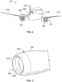
- FIG. 2 illustrates a front perspective view of the aircraft 104, according to an exemplary embodiment of the present disclosure.
- the aircraft 104 includes a propulsion system 212 that includes two engines 102, for example.
- the propulsion system 212 may include more engines 102 than shown.
- the engines 102 are carried by wings 216 of the aircraft 104.
- the engines 102 are carried by a fuselage 218 and/or an empennage 220.
- the empennage 220 may also support horizontal stabilizers 222 and a vertical stabilizer 224.
- the fuselage 218 of the aircraft 104 defines an internal cabin, including a flight deck.
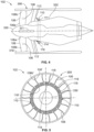
- Figure 3 illustrates a lateral perspective view of an engine 102, according to an embodiment of the present disclosure.
- the engine 102 is a gas turbine engine having a case 300 that includes an engine inlet 314.
- the engine inlet 314 may include a leading edge 316 and an inner barrel section 320 located aft of the leading edge 316 of the engine inlet 314.
- the inner barrel section 320 may provide a boundary surface or wall for directing airflow (not shown) entering the engine inlet 314 and passing through the engine 102.
- the inner barrel section 320 may be located in relatively close proximity to one or more fan blades (not shown in Figure 3 ).
- the inner barrel section 320 may also be configured to serve as an acoustic structure having a plurality of perforations in an inner face sheet of the inner barrel section 320 for absorbing noise generated by the rotating fan blades and/or noise generated by the airflow entering the engine inlet 314 and passing through the engine 102.
- FIG. 4 illustrates a transverse cross-sectional view of the engine 102, according to an embodiment of the present disclosure.
- the engine 102 includes the fan blades 106 coupled to an engine core 330.
- Each fan blade 106 includes a dovetail 106a and an airfoil 106b that is formed unitarily with the dovetail portion 106a.
- Each fan blade 106 further includes a sensor 108, that in the exemplary embodiment, is coupled to, or embedded within, the airfoil 106b.
- a shroud or inner wall 332 is positioned around the engine core 330.
- the housing 110 is secured around the exterior of the inner wall 332. This particular location allows for a low weight compact device design, while protecting the device from the ejected fan blade airfoil. However, it should be realized that this is an exemplary embodiment, and that the device can be placed anywhere on the engine, as long as the device has same rotational axis as the fan blades.
- the housing 110 is formed as a torus 111 that defines an interior tubular chamber 113 that retains the magnetorheological fluid 112. As described with respect to Figure 1 , the housing 110 rotates at the same angular velocity as the fan blades 106, such as via the actuator 120 (shown in Figure 1 ).
- the actuator 120 includes a separate and distinct electric motor 121 operatively coupled to the housing 110.
- the actuator 120 may be the engine core 330, which may be coupled to the housing 110 through, for example, a drive shaft coupled to the accessory gearbox using one or more connecting linkages.
- the actuator 120 may be one or more linkages that connect the housing 110 to the fan rotor shaft 331.
- FIG. 5 illustrates a rear view of the engine 102, according to an embodiment of the present disclosure.
- the electromagnets 118 include coils 119 wrapped around an outer portion of the housing 110. Each electromagnet 118 is radially aligned with and corresponds to an associated fan blade 106.
- the balancing control unit 122 in the event the balancing control unit 122 no longer detects a presence signal 124 from a sensor 108 of the fan blade 106', the balancing control unit 122 outputs an activation signal 126 to the electromagnet 118' associated with the fan blade 106' (determined as missing).
- the activation signal 126 activates the electromagnet 118, such as through electric current.
- the electromagnet 118 is activated, the magnetic particles 116 of the magnetorheological fluid 112 are attracted and drawn to the electromagnet 118, thereby providing mass equal to the missing airfoil portion 106b' of a fan blade 106' at the radial position of the missing fan blade 106'. In this manner, the balancing system 100 ensures mass balance within the engine 102.
- FIG. 6 is a flow chart of a balancing method for an engine of an aircraft, according to an embodiment of the present disclosure.
- the balancing control unit 122 receives the presence signals 124 from the sensors 108 of the fan blades 106.
- the balancing control unit 122 determines if all the fan blades 106 are detected. For example, if presence signals 124 are received from all of the sensors 108 of the fan blades 106, the balancing control unit 122 determines that all the fan blades 106 are detected, and are therefore present within the engine 102. If all the fan blades 106 are detected at 402, the method proceeds to 404, in which the balancing control unit 122 maintains the electromagnets 118 in a deactivated state.
- the method proceeds to 406, at which the balancing control unit 122 activates the electromagnet(s) 118 associated with the missing fan blade(s) 106. Consequently, at 408, the magnetic particles 116 of the magnetorheological fluid 112 within the housing 110 are drawn to the activated electromagnet(s) 118, thereby compensating, at 410, for the missing mass of the fan blade(s) 106.
- embodiments of the present disclosure provide systems and methods for maintaining mass balance within an engine of an aircraft. Further, embodiments of the present disclosure provide systems and methods for maintaining engine balance in the event a fan blade fragments during operation of the engine.
- a structure, limitation, or element that is "configured to” perform a task or operation is particularly structurally formed, constructed, or adapted in a manner corresponding to the task or operation.
- an object that is merely capable of being modified to perform the task or operation is not “configured to” perform the task or operation as used herein.
Landscapes
- Engineering & Computer Science (AREA)
- Mechanical Engineering (AREA)
- General Engineering & Computer Science (AREA)
- Chemical & Material Sciences (AREA)
- Combustion & Propulsion (AREA)
- Aviation & Aerospace Engineering (AREA)
- Structures Of Non-Positive Displacement Pumps (AREA)
Claims (13)
- Auswuchtsystem (100) für einen Motor (102) eines Luftfahrzeugs (104), das Auswuchtsystem (100) aufweisend:ein Gehäuse (110), das eine magnetorheologische Flüssigkeit (112) hält, die magnetische Partikel innerhalb einer Trägerflüssigkeit (114) aufweist;Elektromagnete (118), die an dem Gehäuse (110) gekoppelt sind, wobei die Elektromagnete (118) mit den Fanblättern (106) des Motors (102) verbunden sind, wobei das Gehäuse (110) so konfiguriert ist, dass es mit derselben Winkelgeschwindigkeit wie die Fanblätter (106) rotiert, so dass eine radiale Ausrichtung zwischen den Fanblättern (106) und den Elektromagneten (118) aufrechterhalten wird; undeine Auswuchtsteuereinheit (122), die mit den Elektromagneten (118) und Sensoren (108) der Fanblätter (106) kommuniziert, wobei die Auswuchtsteuereinheit (122) konfiguriert ist, um:Präsenzsignale (124) von den Sensoren (108) der Fanblätter (106) zu empfangen,die Elektromagnete (118) in deaktivierten Zuständen zu halten, wenn die Präsenzsignale (124) von den Sensoren (108) aller Fanblätter (106) erkannt werden, undeinen oder mehrere der Elektromagnete (118) zu aktivieren, wenn eines oder mehrere der Präsenzsignale (124) nicht erkannt werden, wobei die aktivierten Elektromagnete (118) die magnetischen Partikel anziehen, um die fehlende Masse von mindestens einem der Fanblätter (106) auszugleichen und dadurch die Massenbalance innerhalb des Motors (102) aufrechtzuerhalten.
- Auswuchtsystem (100) nach Anspruch 1, wobei das Gehäuse (110) als Torus (111) ausgebildet ist, der eine innere Röhrenkammer (113) definiert, die die magnetorheologische Flüssigkeit (112) hält.
- Auswuchtsystem (100) nach Anspruch 1 oder 2, wobei die Masse der magnetischen Partikel gleich der Masse von mindestens einem der Fanblätter (106) ist.
- Auswuchtsystem (100) nach einem der Ansprüche 1 bis 3, wobei die Anzahl der Elektromagnete (118) der Anzahl der Fanblätter (106) entspricht.
- Auswuchtsystem (100) nach einem der Ansprüche 1 bis 4, wobei die Elektromagnete (118) radial mit den Fanblättern (106) ausgerichtet sind, und wobei jeder der Elektromagnete (118) radial mit einem jeweiligen der Fanblätter (106) ausgerichtet ist.
- Auswuchtsystem (100) nach einem der Ansprüche 1 bis 5, des Weiteren aufweisend einen Aktuator, der betriebsmäßig mit dem Gehäuse (110) gekoppelt ist, wobei der Aktuator das Gehäuse (110) rotiert.
- Auswuchtsystem (100) nach Anspruch 6, wobei der Aktuator einen Elektromotor (121) aufweist.
- Luftfahrzeug (104) aufweisend das Auswuchtsystem (100) nach einem der Ansprüche 1 bis 7.
- Auswuchtverfahren für einen Motor (102) eines Luftfahrzeugs (104), das Auswuchtverfahren aufweisend:Halten einer magnetorheologischen Flüssigkeit (112), die magnetische Partikel innerhalb einer Trägerflüssigkeit (114) enthält, in einem Gehäuse (110);Koppeln von Elektromagneten (118) an das Gehäuse (110);Zuordnen der Elektromagnete (118) zu den Fanblättern (106) des Motors (102); und kommunikatives Koppeln einer Auswuchtsteuereinheit (122) mit den Elektromagneten (118) und Sensoren (108) der Fanblätter (106);das Verfahren des Weiteren aufweisend:Empfangen von Präsenzsignalen durch die Auswuchtsteuereinheit (122) von den Sensoren (108) der Fanblätter (106);Halten der Elektromagnete (118) in deaktivierten Zuständen, wenn die Präsenzsignale von den Sensoren (108) aller Fanblätter (106) erkannt werden;Aktivieren von einem oder mehreren der Elektromagnete (118), wenn eines oder mehrere der Präsenzsignale nicht erkannt werden; undAnziehen der magnetischen Partikel (116) durch die aktivierten Elektromagnete (118), um die fehlende Masse von mindestens einem der Fanblätter (106) auszugleichen und dadurch die Massenbalance innerhalb des Motors aufrechtzuerhalten;das Verfahren des Weiteren aufweisend:Rotieren des Gehäuses (110) mit derselben Winkelgeschwindigkeit wie die Fanblätter (106), so dass eine radiale Ausrichtung zwischen den Fanblättern (106) und den Elektromagneten (118) aufrechterhalten wird.
- Auswuchtverfahren nach Anspruch 9, des Weiteren aufweisend das Ausbilden des Gehäuses (110) als Torus (111), der eine innere Röhrenkammer (113) definiert, die die magnetorheologische Flüssigkeit (112) hält.
- Auswuchtverfahren nach Anspruch 9 oder 10, wobei die Masse der magnetischen Partikel (116) gleich der Masse von mindestens einem der Fanblätter (106) ist.
- Auswuchtverfahren nach einem der Ansprüche 9 bis 11, wobei das Zuordnen das radiale Ausrichten der Elektromagnete (118) mit den Fanblättern (106) aufweist, und wobei jeder der Elektromagnete (118) radial mit einem jeweiligen der Fanblätter (106) ausgerichtet ist.
- Auswuchtverfahren nach einem der Ansprüche 9 bis 12, des Weiteren aufweisend das betriebsmäßige Koppeln eines Aktuators an das Gehäuse (110), wobei das Rotieren durch den Aktuator erfolgt.
Applications Claiming Priority (1)
| Application Number | Priority Date | Filing Date | Title |
|---|---|---|---|
| US16/732,580 US11261740B2 (en) | 2020-01-02 | 2020-01-02 | Balancing systems and methods for an engine of an aircraft |
Publications (2)
| Publication Number | Publication Date |
|---|---|
| EP3845739A1 EP3845739A1 (de) | 2021-07-07 |
| EP3845739B1 true EP3845739B1 (de) | 2024-08-07 |
Family
ID=73014297
Family Applications (1)
| Application Number | Title | Priority Date | Filing Date |
|---|---|---|---|
| EP20203568.9A Active EP3845739B1 (de) | 2020-01-02 | 2020-10-23 | Auswuchtungssystem und verfahren für einen motor eines flugzeugs |
Country Status (3)
| Country | Link |
|---|---|
| US (1) | US11261740B2 (de) |
| EP (1) | EP3845739B1 (de) |
| CN (1) | CN113062797B (de) |
Families Citing this family (1)
| Publication number | Priority date | Publication date | Assignee | Title |
|---|---|---|---|---|
| US12297748B2 (en) * | 2023-03-20 | 2025-05-13 | Pratt & Whitney Canada Corp. | System and method of performing fan trim balancing |
Family Cites Families (11)
| Publication number | Priority date | Publication date | Assignee | Title |
|---|---|---|---|---|
| US5082421A (en) * | 1986-04-28 | 1992-01-21 | Rolls-Royce Plc | Active control of unsteady motion phenomena in turbomachinery |
| GB2319812A (en) * | 1996-10-15 | 1998-06-03 | Balfan Corp | In-flight balancing of fan on turbofan jet engine |
| FR2817912B1 (fr) * | 2000-12-07 | 2003-01-17 | Hispano Suiza Sa | Reducteur reprenant les efforts axiaux generes par la soufflante d'un turboreacteur |
| US10119412B2 (en) | 2013-03-13 | 2018-11-06 | United Technologies Corporation | Turbine engine adaptive low leakage air seal |
| FR3004748B1 (fr) * | 2013-04-19 | 2015-04-10 | Snecma | Aube ou pale de moteur d'aeronef et procede et systeme de controle de defauts dans des composites par des particules ayant des proprietes ferromagnetiques |
| US10465557B2 (en) | 2015-09-01 | 2019-11-05 | Rolls-Royce North American Technologies, Inc. | Magnetic squeeze film damper system for a gas turbine engine |
| US10240909B2 (en) * | 2016-10-17 | 2019-03-26 | The Boeing Company | Three-dimensional gap measurement systems and methods |
| US11002335B2 (en) * | 2016-11-08 | 2021-05-11 | General Electric Company | Controllable magneto-rheological device for gas turbine engine |
| US10822965B2 (en) * | 2018-03-26 | 2020-11-03 | General Electric Company | Active airfoil vibration control |
| CN209398455U (zh) | 2018-12-05 | 2019-09-17 | 中国航发商用航空发动机有限责任公司 | 一种航空发动机及其叶片 |
| US10954932B2 (en) * | 2019-03-05 | 2021-03-23 | Tung Thanh NGUYEN | Electromagnetic cooling fan |
-
2020
- 2020-01-02 US US16/732,580 patent/US11261740B2/en active Active
- 2020-10-23 EP EP20203568.9A patent/EP3845739B1/de active Active
- 2020-11-09 CN CN202011242056.XA patent/CN113062797B/zh active Active
Also Published As
| Publication number | Publication date |
|---|---|
| US20210207485A1 (en) | 2021-07-08 |
| EP3845739A1 (de) | 2021-07-07 |
| CN113062797A (zh) | 2021-07-02 |
| CN113062797B (zh) | 2025-01-24 |
| US11261740B2 (en) | 2022-03-01 |
Similar Documents
| Publication | Publication Date | Title |
|---|---|---|
| US6195982B1 (en) | Apparatus and method of active flutter control | |
| US8075249B2 (en) | System and a method for dynamically balancing a blade | |
| EP3093440A1 (de) | Gebläseschaufelschwingungsüberwachungs- und -steuerungssystem und -verfahren | |
| CN105986907A (zh) | 燃气涡轮发动机健康确定 | |
| EP3845739B1 (de) | Auswuchtungssystem und verfahren für einen motor eines flugzeugs | |
| WO2016054171A1 (en) | Rotor speed management | |
| US5230603A (en) | Control of flow instabilities in turbomachines | |
| EP3001560A2 (de) | System und verfahren zur geräuschverminderung in einem luftbewegungssystem | |
| EP3333082A1 (de) | Schubmessvorrichtung für ein antriebssystem | |
| EP2873813A1 (de) | System und Verfahren zur aktiven Regelung des Schaufelspitzenspiels von Gasturbinenmotorturbinen | |
| EP3293385A1 (de) | Gasturbinentriebwerk mit progressiver strömungsabrisswiederherstellung | |
| EP2728126A1 (de) | System zur Verringerung der Überdrehzahl eines Gasturbinentriebwerks | |
| CN110821571A (zh) | 用于阻尼轴振动的阻尼装置 | |
| US10822965B2 (en) | Active airfoil vibration control | |
| US12421864B2 (en) | Controlling excitation loads associated with open rotor aeronautical engines | |
| US12491988B2 (en) | Controlling excitation loads associated with open rotor aeronautical engines | |
| CN114909216A (zh) | 主动式压缩机失速恢复 | |
| EP3241987B1 (de) | Rotorauswuchtung | |
| US20140260323A1 (en) | Gas turbine engine and active balancing system | |
| CN113418709A (zh) | 一种机匣包容试验装置及其设计方法 | |
| EP3889035B1 (de) | Motorintegrierte fluidmaschine und vertikal startendes und landendes flugzeug | |
| US20250179964A1 (en) | Variable bleed valve assemblies | |
| EP3090952B1 (de) | Triebwerksgondel | |
| CN107531321B (zh) | 用于飞机的消音设备 | |
| CN111985046A (zh) | 模态成形的部件 |
Legal Events
| Date | Code | Title | Description |
|---|---|---|---|
| PUAI | Public reference made under article 153(3) epc to a published international application that has entered the european phase |
Free format text: ORIGINAL CODE: 0009012 |
|
| STAA | Information on the status of an ep patent application or granted ep patent |
Free format text: STATUS: THE APPLICATION HAS BEEN PUBLISHED |
|
| AK | Designated contracting states |
Kind code of ref document: A1 Designated state(s): AL AT BE BG CH CY CZ DE DK EE ES FI FR GB GR HR HU IE IS IT LI LT LU LV MC MK MT NL NO PL PT RO RS SE SI SK SM TR |
|
| STAA | Information on the status of an ep patent application or granted ep patent |
Free format text: STATUS: REQUEST FOR EXAMINATION WAS MADE |
|
| 17P | Request for examination filed |
Effective date: 20211118 |
|
| RBV | Designated contracting states (corrected) |
Designated state(s): AL AT BE BG CH CY CZ DE DK EE ES FI FR GB GR HR HU IE IS IT LI LT LU LV MC MK MT NL NO PL PT RO RS SE SI SK SM TR |
|
| RAP3 | Party data changed (applicant data changed or rights of an application transferred) |
Owner name: THE BOEING COMPANY |
|
| STAA | Information on the status of an ep patent application or granted ep patent |
Free format text: STATUS: EXAMINATION IS IN PROGRESS |
|
| 17Q | First examination report despatched |
Effective date: 20230619 |
|
| GRAP | Despatch of communication of intention to grant a patent |
Free format text: ORIGINAL CODE: EPIDOSNIGR1 |
|
| STAA | Information on the status of an ep patent application or granted ep patent |
Free format text: STATUS: GRANT OF PATENT IS INTENDED |
|
| INTG | Intention to grant announced |
Effective date: 20240322 |
|
| GRAS | Grant fee paid |
Free format text: ORIGINAL CODE: EPIDOSNIGR3 |
|
| GRAA | (expected) grant |
Free format text: ORIGINAL CODE: 0009210 |
|
| STAA | Information on the status of an ep patent application or granted ep patent |
Free format text: STATUS: THE PATENT HAS BEEN GRANTED |
|
| P01 | Opt-out of the competence of the unified patent court (upc) registered |
Free format text: CASE NUMBER: APP_33065/2024 Effective date: 20240603 |
|
| AK | Designated contracting states |
Kind code of ref document: B1 Designated state(s): AL AT BE BG CH CY CZ DE DK EE ES FI FR GB GR HR HU IE IS IT LI LT LU LV MC MK MT NL NO PL PT RO RS SE SI SK SM TR |
|
| REG | Reference to a national code |
Ref country code: GB Ref legal event code: FG4D |
|
| REG | Reference to a national code |
Ref country code: CH Ref legal event code: EP |
|
| REG | Reference to a national code |
Ref country code: IE Ref legal event code: FG4D |
|
| REG | Reference to a national code |
Ref country code: DE Ref legal event code: R096 Ref document number: 602020035210 Country of ref document: DE |
|
| REG | Reference to a national code |
Ref country code: LT Ref legal event code: MG9D |
|
| REG | Reference to a national code |
Ref country code: NL Ref legal event code: MP Effective date: 20240807 |
|
| PG25 | Lapsed in a contracting state [announced via postgrant information from national office to epo] |
Ref country code: NO Free format text: LAPSE BECAUSE OF FAILURE TO SUBMIT A TRANSLATION OF THE DESCRIPTION OR TO PAY THE FEE WITHIN THE PRESCRIBED TIME-LIMIT Effective date: 20241107 |
|
| REG | Reference to a national code |
Ref country code: AT Ref legal event code: MK05 Ref document number: 1711146 Country of ref document: AT Kind code of ref document: T Effective date: 20240807 |
|
| PG25 | Lapsed in a contracting state [announced via postgrant information from national office to epo] |
Ref country code: GR Free format text: LAPSE BECAUSE OF FAILURE TO SUBMIT A TRANSLATION OF THE DESCRIPTION OR TO PAY THE FEE WITHIN THE PRESCRIBED TIME-LIMIT Effective date: 20241108 Ref country code: FI Free format text: LAPSE BECAUSE OF FAILURE TO SUBMIT A TRANSLATION OF THE DESCRIPTION OR TO PAY THE FEE WITHIN THE PRESCRIBED TIME-LIMIT Effective date: 20240807 Ref country code: NL Free format text: LAPSE BECAUSE OF FAILURE TO SUBMIT A TRANSLATION OF THE DESCRIPTION OR TO PAY THE FEE WITHIN THE PRESCRIBED TIME-LIMIT Effective date: 20240807 Ref country code: PT Free format text: LAPSE BECAUSE OF FAILURE TO SUBMIT A TRANSLATION OF THE DESCRIPTION OR TO PAY THE FEE WITHIN THE PRESCRIBED TIME-LIMIT Effective date: 20241209 Ref country code: PL Free format text: LAPSE BECAUSE OF FAILURE TO SUBMIT A TRANSLATION OF THE DESCRIPTION OR TO PAY THE FEE WITHIN THE PRESCRIBED TIME-LIMIT Effective date: 20240807 |
|
| PG25 | Lapsed in a contracting state [announced via postgrant information from national office to epo] |
Ref country code: BG Free format text: LAPSE BECAUSE OF FAILURE TO SUBMIT A TRANSLATION OF THE DESCRIPTION OR TO PAY THE FEE WITHIN THE PRESCRIBED TIME-LIMIT Effective date: 20240807 |
|
| PG25 | Lapsed in a contracting state [announced via postgrant information from national office to epo] |
Ref country code: LV Free format text: LAPSE BECAUSE OF FAILURE TO SUBMIT A TRANSLATION OF THE DESCRIPTION OR TO PAY THE FEE WITHIN THE PRESCRIBED TIME-LIMIT Effective date: 20240807 |
|
| PG25 | Lapsed in a contracting state [announced via postgrant information from national office to epo] |
Ref country code: IS Free format text: LAPSE BECAUSE OF FAILURE TO SUBMIT A TRANSLATION OF THE DESCRIPTION OR TO PAY THE FEE WITHIN THE PRESCRIBED TIME-LIMIT Effective date: 20241207 Ref country code: AT Free format text: LAPSE BECAUSE OF FAILURE TO SUBMIT A TRANSLATION OF THE DESCRIPTION OR TO PAY THE FEE WITHIN THE PRESCRIBED TIME-LIMIT Effective date: 20240807 |
|
| PG25 | Lapsed in a contracting state [announced via postgrant information from national office to epo] |
Ref country code: HR Free format text: LAPSE BECAUSE OF FAILURE TO SUBMIT A TRANSLATION OF THE DESCRIPTION OR TO PAY THE FEE WITHIN THE PRESCRIBED TIME-LIMIT Effective date: 20240807 |
|
| PG25 | Lapsed in a contracting state [announced via postgrant information from national office to epo] |
Ref country code: RS Free format text: LAPSE BECAUSE OF FAILURE TO SUBMIT A TRANSLATION OF THE DESCRIPTION OR TO PAY THE FEE WITHIN THE PRESCRIBED TIME-LIMIT Effective date: 20241107 Ref country code: ES Free format text: LAPSE BECAUSE OF FAILURE TO SUBMIT A TRANSLATION OF THE DESCRIPTION OR TO PAY THE FEE WITHIN THE PRESCRIBED TIME-LIMIT Effective date: 20240807 |
|
| PG25 | Lapsed in a contracting state [announced via postgrant information from national office to epo] |
Ref country code: RS Free format text: LAPSE BECAUSE OF FAILURE TO SUBMIT A TRANSLATION OF THE DESCRIPTION OR TO PAY THE FEE WITHIN THE PRESCRIBED TIME-LIMIT Effective date: 20241107 Ref country code: PT Free format text: LAPSE BECAUSE OF FAILURE TO SUBMIT A TRANSLATION OF THE DESCRIPTION OR TO PAY THE FEE WITHIN THE PRESCRIBED TIME-LIMIT Effective date: 20241209 Ref country code: PL Free format text: LAPSE BECAUSE OF FAILURE TO SUBMIT A TRANSLATION OF THE DESCRIPTION OR TO PAY THE FEE WITHIN THE PRESCRIBED TIME-LIMIT Effective date: 20240807 Ref country code: NO Free format text: LAPSE BECAUSE OF FAILURE TO SUBMIT A TRANSLATION OF THE DESCRIPTION OR TO PAY THE FEE WITHIN THE PRESCRIBED TIME-LIMIT Effective date: 20241107 Ref country code: NL Free format text: LAPSE BECAUSE OF FAILURE TO SUBMIT A TRANSLATION OF THE DESCRIPTION OR TO PAY THE FEE WITHIN THE PRESCRIBED TIME-LIMIT Effective date: 20240807 Ref country code: LV Free format text: LAPSE BECAUSE OF FAILURE TO SUBMIT A TRANSLATION OF THE DESCRIPTION OR TO PAY THE FEE WITHIN THE PRESCRIBED TIME-LIMIT Effective date: 20240807 Ref country code: IS Free format text: LAPSE BECAUSE OF FAILURE TO SUBMIT A TRANSLATION OF THE DESCRIPTION OR TO PAY THE FEE WITHIN THE PRESCRIBED TIME-LIMIT Effective date: 20241207 Ref country code: HR Free format text: LAPSE BECAUSE OF FAILURE TO SUBMIT A TRANSLATION OF THE DESCRIPTION OR TO PAY THE FEE WITHIN THE PRESCRIBED TIME-LIMIT Effective date: 20240807 Ref country code: GR Free format text: LAPSE BECAUSE OF FAILURE TO SUBMIT A TRANSLATION OF THE DESCRIPTION OR TO PAY THE FEE WITHIN THE PRESCRIBED TIME-LIMIT Effective date: 20241108 Ref country code: FI Free format text: LAPSE BECAUSE OF FAILURE TO SUBMIT A TRANSLATION OF THE DESCRIPTION OR TO PAY THE FEE WITHIN THE PRESCRIBED TIME-LIMIT Effective date: 20240807 Ref country code: ES Free format text: LAPSE BECAUSE OF FAILURE TO SUBMIT A TRANSLATION OF THE DESCRIPTION OR TO PAY THE FEE WITHIN THE PRESCRIBED TIME-LIMIT Effective date: 20240807 Ref country code: BG Free format text: LAPSE BECAUSE OF FAILURE TO SUBMIT A TRANSLATION OF THE DESCRIPTION OR TO PAY THE FEE WITHIN THE PRESCRIBED TIME-LIMIT Effective date: 20240807 Ref country code: AT Free format text: LAPSE BECAUSE OF FAILURE TO SUBMIT A TRANSLATION OF THE DESCRIPTION OR TO PAY THE FEE WITHIN THE PRESCRIBED TIME-LIMIT Effective date: 20240807 |
|
| PG25 | Lapsed in a contracting state [announced via postgrant information from national office to epo] |
Ref country code: SM Free format text: LAPSE BECAUSE OF FAILURE TO SUBMIT A TRANSLATION OF THE DESCRIPTION OR TO PAY THE FEE WITHIN THE PRESCRIBED TIME-LIMIT Effective date: 20240807 Ref country code: DK Free format text: LAPSE BECAUSE OF FAILURE TO SUBMIT A TRANSLATION OF THE DESCRIPTION OR TO PAY THE FEE WITHIN THE PRESCRIBED TIME-LIMIT Effective date: 20240807 |
|
| PG25 | Lapsed in a contracting state [announced via postgrant information from national office to epo] |
Ref country code: EE Free format text: LAPSE BECAUSE OF FAILURE TO SUBMIT A TRANSLATION OF THE DESCRIPTION OR TO PAY THE FEE WITHIN THE PRESCRIBED TIME-LIMIT Effective date: 20240807 |
|
| PG25 | Lapsed in a contracting state [announced via postgrant information from national office to epo] |
Ref country code: CZ Free format text: LAPSE BECAUSE OF FAILURE TO SUBMIT A TRANSLATION OF THE DESCRIPTION OR TO PAY THE FEE WITHIN THE PRESCRIBED TIME-LIMIT Effective date: 20240807 |
|
| PG25 | Lapsed in a contracting state [announced via postgrant information from national office to epo] |
Ref country code: SK Free format text: LAPSE BECAUSE OF FAILURE TO SUBMIT A TRANSLATION OF THE DESCRIPTION OR TO PAY THE FEE WITHIN THE PRESCRIBED TIME-LIMIT Effective date: 20240807 |
|
| REG | Reference to a national code |
Ref country code: DE Ref legal event code: R119 Ref document number: 602020035210 Country of ref document: DE |
|
| REG | Reference to a national code |
Ref country code: CH Ref legal event code: PL |
|
| PLBE | No opposition filed within time limit |
Free format text: ORIGINAL CODE: 0009261 |
|
| STAA | Information on the status of an ep patent application or granted ep patent |
Free format text: STATUS: NO OPPOSITION FILED WITHIN TIME LIMIT |
|
| PG25 | Lapsed in a contracting state [announced via postgrant information from national office to epo] |
Ref country code: MC Free format text: LAPSE BECAUSE OF FAILURE TO SUBMIT A TRANSLATION OF THE DESCRIPTION OR TO PAY THE FEE WITHIN THE PRESCRIBED TIME-LIMIT Effective date: 20240807 |
|
| PG25 | Lapsed in a contracting state [announced via postgrant information from national office to epo] |
Ref country code: DE Free format text: LAPSE BECAUSE OF NON-PAYMENT OF DUE FEES Effective date: 20250501 |
|
| PG25 | Lapsed in a contracting state [announced via postgrant information from national office to epo] |
Ref country code: LU Free format text: LAPSE BECAUSE OF NON-PAYMENT OF DUE FEES Effective date: 20241023 Ref country code: BE Free format text: LAPSE BECAUSE OF NON-PAYMENT OF DUE FEES Effective date: 20241031 |
|
| 26N | No opposition filed |
Effective date: 20250508 |
|
| PG25 | Lapsed in a contracting state [announced via postgrant information from national office to epo] |
Ref country code: FR Free format text: LAPSE BECAUSE OF NON-PAYMENT OF DUE FEES Effective date: 20241031 |
|
| GBPC | Gb: european patent ceased through non-payment of renewal fee |
Effective date: 20241107 |
|
| PG25 | Lapsed in a contracting state [announced via postgrant information from national office to epo] |
Ref country code: CH Free format text: LAPSE BECAUSE OF NON-PAYMENT OF DUE FEES Effective date: 20241031 |
|
| REG | Reference to a national code |
Ref country code: BE Ref legal event code: MM Effective date: 20241031 |
|
| PG25 | Lapsed in a contracting state [announced via postgrant information from national office to epo] |
Ref country code: SE Free format text: LAPSE BECAUSE OF FAILURE TO SUBMIT A TRANSLATION OF THE DESCRIPTION OR TO PAY THE FEE WITHIN THE PRESCRIBED TIME-LIMIT Effective date: 20240807 |
|
| PG25 | Lapsed in a contracting state [announced via postgrant information from national office to epo] |
Ref country code: GB Free format text: LAPSE BECAUSE OF NON-PAYMENT OF DUE FEES Effective date: 20241107 |
|
| PG25 | Lapsed in a contracting state [announced via postgrant information from national office to epo] |
Ref country code: IE Free format text: LAPSE BECAUSE OF NON-PAYMENT OF DUE FEES Effective date: 20241023 |
|
| PG25 | Lapsed in a contracting state [announced via postgrant information from national office to epo] |
Ref country code: RO Free format text: LAPSE BECAUSE OF FAILURE TO SUBMIT A TRANSLATION OF THE DESCRIPTION OR TO PAY THE FEE WITHIN THE PRESCRIBED TIME-LIMIT Effective date: 20240807 |
|
| PG25 | Lapsed in a contracting state [announced via postgrant information from national office to epo] |
Ref country code: CY Free format text: LAPSE BECAUSE OF FAILURE TO SUBMIT A TRANSLATION OF THE DESCRIPTION OR TO PAY THE FEE WITHIN THE PRESCRIBED TIME-LIMIT; INVALID AB INITIO Effective date: 20201023 Ref country code: IT Free format text: LAPSE BECAUSE OF FAILURE TO SUBMIT A TRANSLATION OF THE DESCRIPTION OR TO PAY THE FEE WITHIN THE PRESCRIBED TIME-LIMIT Effective date: 20240807 |
|
| PG25 | Lapsed in a contracting state [announced via postgrant information from national office to epo] |
Ref country code: HU Free format text: LAPSE BECAUSE OF FAILURE TO SUBMIT A TRANSLATION OF THE DESCRIPTION OR TO PAY THE FEE WITHIN THE PRESCRIBED TIME-LIMIT; INVALID AB INITIO Effective date: 20201023 |