EP2728126A1 - System zur Verringerung der Überdrehzahl eines Gasturbinentriebwerks - Google Patents
System zur Verringerung der Überdrehzahl eines Gasturbinentriebwerks Download PDFInfo
- Publication number
- EP2728126A1 EP2728126A1 EP12198693.9A EP12198693A EP2728126A1 EP 2728126 A1 EP2728126 A1 EP 2728126A1 EP 12198693 A EP12198693 A EP 12198693A EP 2728126 A1 EP2728126 A1 EP 2728126A1
- Authority
- EP
- European Patent Office
- Prior art keywords
- gas generator
- engine
- delta
- valve
- turbine
- Prior art date
- Legal status (The legal status is an assumption and is not a legal conclusion. Google has not performed a legal analysis and makes no representation as to the accuracy of the status listed.)
- Granted
Links
Images


Classifications
-
- F—MECHANICAL ENGINEERING; LIGHTING; HEATING; WEAPONS; BLASTING
- F01—MACHINES OR ENGINES IN GENERAL; ENGINE PLANTS IN GENERAL; STEAM ENGINES
- F01D—NON-POSITIVE DISPLACEMENT MACHINES OR ENGINES, e.g. STEAM TURBINES
- F01D17/00—Regulating or controlling by varying flow
- F01D17/02—Arrangement of sensing elements
- F01D17/06—Arrangement of sensing elements responsive to speed
-
- F—MECHANICAL ENGINEERING; LIGHTING; HEATING; WEAPONS; BLASTING
- F01—MACHINES OR ENGINES IN GENERAL; ENGINE PLANTS IN GENERAL; STEAM ENGINES
- F01D—NON-POSITIVE DISPLACEMENT MACHINES OR ENGINES, e.g. STEAM TURBINES
- F01D21/00—Shutting-down of machines or engines, e.g. in emergency; Regulating, controlling, or safety means not otherwise provided for
- F01D21/02—Shutting-down responsive to overspeed
-
- F—MECHANICAL ENGINEERING; LIGHTING; HEATING; WEAPONS; BLASTING
- F02—COMBUSTION ENGINES; HOT-GAS OR COMBUSTION-PRODUCT ENGINE PLANTS
- F02C—GAS-TURBINE PLANTS; AIR INTAKES FOR JET-PROPULSION PLANTS; CONTROLLING FUEL SUPPLY IN AIR-BREATHING JET-PROPULSION PLANTS
- F02C9/00—Controlling gas-turbine plants; Controlling fuel supply in air- breathing jet-propulsion plants
- F02C9/26—Control of fuel supply
- F02C9/28—Regulating systems responsive to plant or ambient parameters, e.g. temperature, pressure, rotor speed
-
- F—MECHANICAL ENGINEERING; LIGHTING; HEATING; WEAPONS; BLASTING
- F02—COMBUSTION ENGINES; HOT-GAS OR COMBUSTION-PRODUCT ENGINE PLANTS
- F02C—GAS-TURBINE PLANTS; AIR INTAKES FOR JET-PROPULSION PLANTS; CONTROLLING FUEL SUPPLY IN AIR-BREATHING JET-PROPULSION PLANTS
- F02C9/00—Controlling gas-turbine plants; Controlling fuel supply in air- breathing jet-propulsion plants
- F02C9/26—Control of fuel supply
- F02C9/46—Emergency fuel control
-
- F—MECHANICAL ENGINEERING; LIGHTING; HEATING; WEAPONS; BLASTING
- F05—INDEXING SCHEMES RELATING TO ENGINES OR PUMPS IN VARIOUS SUBCLASSES OF CLASSES F01-F04
- F05D—INDEXING SCHEME FOR ASPECTS RELATING TO NON-POSITIVE-DISPLACEMENT MACHINES OR ENGINES, GAS-TURBINES OR JET-PROPULSION PLANTS
- F05D2270/00—Control
- F05D2270/01—Purpose of the control system
- F05D2270/02—Purpose of the control system to control rotational speed (n)
- F05D2270/021—Purpose of the control system to control rotational speed (n) to prevent overspeed
Definitions
- the present disclosure relates to a system and method for protecting an engine and other aircraft components from damage that may otherwise occur from a fuel control unit failure.
- the system and method of the present disclosure are configured to protect aircraft components from an engine overspeeding condition that may result from a fuel control unit failure.
- a failure mode of a fuel control unit malfunction can include an oversupply of fuel to the turbine engine, thereby causing an overspeeding condition in the engine.
- the overspeeding condition can result in damage to aircraft components, such as the engine, generator, gearbox, rotor system, hydraulic pump, and electrical system, to name a few examples.
- an overspeeding condition can result in an unintended aircraft takeoff, particularly when the aircraft is a tiltrotor aircraft that may have a high amount of built-in twist in the rotor blades.
- the system and method of the present disclosure are configured to mitigate the negative impacts of an overspeeding condition on the engine.
- Rotorcraft 101 has a rotor system 103 with a plurality of rotor blades 105. The pitch of each rotor blade 105 can be managed in order to selectively control direction, thrust, and lift of rotorcraft 101.
- Rotorcraft 101 further includes a fuselage 107, anti-torque system 109, and an empennage 111. Torque is supplied to rotor system 103 and anti-torque system 109 with at least one engine 113.
- a main rotor gearbox 115 is operably associated with the engine main output driveshaft and the main rotor mast. Further, a reduction speed gearbox 139 and an intermediate gearbox 117 can be operably associated with a tail rotor drive shaft 119 and a tail rotor drive shaft 121.
- Tilt rotor aircraft 201 can include nacelles 203a and 203b, a wing 205, a fuselage 207, and a tail member 209.
- Each nacelle 203a and 203b can include an engine and gearbox for driving rotor systems 211a and 211b, respectively.
- Nacelles 203a and 203b are each configured to rotate between a helicopter mode, in which the nacelles 203a and 203b are approximately vertical, and an airplane mode, in which the nacelles 203a and 203b are approximately horizontal.
- Rotorcraft 101 and tilt rotor aircraft 201 are merely illustrative of the wide variety of aircraft and vehicles that are particularly well suited to take advantage of the method and system of the present disclosure. It should be appreciated that other vehicles having a turbine engine can implement the system and method of the present disclosure.
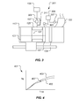
- Engine 113 can include a compressor 123, a combustion chamber 125, a gas generator turbine 127, and a power turbine 129.
- a combination of compressor 123 and gas generator turbine 127 can be referred to as a gas generator.
- a drive shaft 131 can provide torque transfer between compressor 123 and gas generator turbine 127.
- An exhaust duct 133 provides for the discharge of hot exhaust gas from engine 113.
- a fuel supply 135 is configured to provide fuel flow to combustion chamber 125 via a fuel control unit 137.
- Fuel control unit 137 can be selectively controlled by a pilot and/or engine system controls for selectively controlling the output power of engine 113. It should be appreciated that system 301 can be implemented in conjunction with each engine located in the aircraft. For example, an aircraft having two engines can have two systems 301.
- System 301 is configured to protect aircraft components from an engine overspeeding condition that may result from a failure of fuel control unit 137.
- a failure mode of a malfunction of fuel control unit 137 can include an oversupply of fuel to engine 113, thereby causing an overspeeding condition in the engine 113.
- System 301 is also configured to prevent an unintended takeoff that may otherwise occur from a failure of fuel control unit 137 while the aircraft is on the ground.
- System 301 can include a sensor 303 configured for measuring an actual gas generator turbine speed (Ng).
- Sensor 303 can be any variety of suitable sensors capable of measuring rotational speed of gas generator turbine 127, such as a magnetic pickup sensor for example.
- Sensor 303 is in data communication with a processor 305.
- Processor 305 is configured for actively comparing a measured gas generator turbine speed (Ng) with a predicted gas generator turbine speed, the predicted gas generator turbine speed being a function of the commanded amount of fuel flow to fuel control unit 137.
- a graph 401 graphically illustrates a delta 407 between the predicted gas generator turbine speed 405 and the measured gas generator turbine speed 403.
- delta 407 is greater than a predetermined threshold value, then a malfunction of fuel control unit 137 can be identified.
- a threshold value is surpassed when the measured gas generator turbine speed 403 is 113% of the predicted gas generator turbine speed 405; however, it should be appreciated that the exact threshold value is implementation specific. Further, several different threshold values can be used depending on the operational situation of the aircraft, as discussed further herein with regard to method 501.
- processor 305 uses a filter in the analysis of comparing delta 407 between the predicted gas generator turbine speed 405 and the measured gas generator turbine speed 403 to the threshold value so that steady state error between the predicted gas generator turbine speed 405 and the measured gas generator turbine speed 403 is removed.
- the filter can be operable to remove steady state error that may result from mechanical and electrical tolerances in the fuel control interfaces that can impact the accuracy of the calculation of delta 407.
- System 301 can also include a sensor 307 configured for measuring exhaust temperature (MgT) as a redundancy to the comparison between delta 407 and the predetermined threshold value. For example, before a downstream command is made that can cause a reduction or termination of fuel flow to engine 113, processor 305 can be configured to confirm malfunction of fuel control unit 137 by a comparable increase in exhaust temperature (MgT).
- MgT exhaust temperature
- system 301 is configured such that once a malfunction of fuel control unit 137 is determined, a command is sent to a valve 309 so that fuel is redirected from fuel control unit 137 to a fluid path having an inline restrictor valve 311.
- Restrictor valve 311 is configured to restrict fuel flow to a rate that prevents an overspeeding of engine 113 while still providing enough fuel for engine 113 to operate. It should be appreciated that restrictor valve 311 is merely illustrative of an implementation specific device for limiting fuel flow to combustion chamber 125 of engine 113.
- valve 309 is configured to completely terminate fuel flow to engine combustion chamber 125 of engine 113 instead of redirecting fuel through restrictor valve 311.
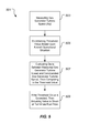
- a method 501 is configured to protect aircraft components from an engine overspeeding condition that may result from a failure of fuel control unit 137.
- Method 501 is also configured to prevent an unintended takeoff that may otherwise occur from a failure of fuel control unit 137 while the aircraft is on the ground.
- Method 501 can include a step of measuring the speed of gas generator turbine 127, thereby deriving a gas generator turbine speed (Ng). Step 503 can be implemented by using sensor 303 described further herein with regard to system 301.
- Method 501 can also include a step 505 for establishing a threshold value based upon the operational situation of the aircraft.
- a lower threshold value can be used so that the fuel flow to the engine is reduced or terminated in a shorter amount of time as compared to the use of a higher threshold value.
- an on the ground threshold value can be surpassed when the measured gas generator turbine speed (illustrated as 403 in Figure 4 ) is approximately 105% of the predicted gas generator turbine speed (illustrated as 405 in Figure 4 ), whereas an in-flight threshold value can be surpassed when the measured gas generator turbine speed is approximately 113% of the predicted gas generator turbine speed; however, it should be appreciated that the exact ground threshold values and in-flight threshold values are implementation specific.
- Method 501 can also include a step 507 for evaluating how the delta (illustrated as 407 in Figure 4 ) between the measured gas generator turbine speed and the predicted gas generator turbine speed compares to the threshold value. If the delta does not exceed the threshold value, then no action is taken. On the other hand, if the delta does exceed the threshold value, then a step 509 can be implemented.
- step 507 can also include confirming a malfunction of the fuel control unit 137 by verifying that an increase in gas generator turbine 127 speed is also resulting in a equivalent increase in exhaust temperature (MgT).
- Step 509 can include actuating valve 309 so that fuel flow is diverted through restrictor valve 311.
- actuating valve 309 causes fuel flow to be terminated, as discussed further herein with regard to system 301.
- System 601 is schematically illustrated.
- System 601 is configured for performing one or more functions with regard to the operation of system 301 and method 501, further disclosed herein. Further, any processing and analysis can be partly or fully performed by computer system 601. Computer system 601 can be partly or fully integrated with other aircraft computer systems.
- the system 601 can include an input/output (I/O) interface 603, an analysis engine 605, and a database 607. Alternative embodiments can combine or distribute the input/output (I/O) interface 603, analysis engine 605, and database 607, as desired.
- Embodiments of the system 601 can include one or more computers that include one or more processors and memories configured for performing tasks described herein. This can include, for example, a computer having a central processing unit (CPU) and non-volatile memory that stores software instructions for instructing the CPU to perform at least some of the tasks described herein.
- CPU central processing unit
- This can also include, for example, two or more computers that are in communication via a computer network, where one or more of the computers include a CPU and non-volatile memory, and one or more of the computer's non-volatile memory stores software instructions for instructing any of the CPU(s) to perform any of the tasks described herein.
- the exemplary embodiment is described in terms of a discrete machine, it should be appreciated that this description is non-limiting, and that the present description applies equally to numerous other arrangements involving one or more machines performing tasks distributed in any way among the one or more machines. It should also be appreciated that such machines need not be dedicated to performing tasks described herein, but instead can be multi-purpose machines, for example computer workstations, that are suitable for also performing other tasks.
- the I/O interface 603 can provide a communication link between external users, systems, and data sources and components of the system 601.
- the I/O interface 603 can be configured for allowing one or more users to input information to the system 601 via any known input device. Examples can include a keyboard, mouse, touch screen, and/or any other desired input device.
- the I/O interface 603 can be configured for allowing one or more users to receive information output from the system 601 via any known output device. Examples can include a display monitor, a printer, cockpit display, and/or any other desired output device.
- the I/O interface 603 can be configured for allowing other systems to communicate with the system 601.
- the I/O interface 603 can allow one or more remote computer(s) to access information, input information, and/or remotely instruct the system 601 to perform one or more of the tasks described herein.
- the I/O interface 603 can be configured for allowing communication with one or more remote data sources.
- the I/O interface 603 can allow one or more remote data source(s) to access information, input information, and/or remotely instruct the system 601 to perform one or more of the tasks described herein.
- the database 607 provides persistent data storage for system 601. While the term "database" is primarily used, a memory or other suitable data storage arrangement may provide the functionality of the database 607. In alternative embodiments, the database 607 can be integral to or separate from the system 601 and can operate on one or more computers. The database 607 preferably provides non-volatile data storage for any information suitable to support the operation of system 301 and method 501, including various types of data discussed further herein.
- the analysis engine 605 can be configured for comparing the delta between the measured gas generator turbine speed and the commanded gas generator turbine speed, then comparing the delta to the threshold value. Further, analysis engine can be in lieu of processor 305, or integrated therewith.
- the analysis engine 605 can include various combinations of one or more processors, memories, and software components.
- System 301 and method 501 provide significant advantages over conventional means of detecting and mitigating a fuel control unit failure that may result in an overspeeding condition in the engine. The amount of time that is required to detect and mitigate an overspeeding condition is very critical. For example, in one illustrative embodiment, approximately 1.0 seconds after the fuel control unit failure, the rotor system can reach the design maximum.
- the overspeeding condition may cause a failure of a power supply that may be operable with other flight critical systems.
- a complete inspection of the drive system may be required.
- a qualification limit can be reached for the aircraft generators.
- the system and method of the present disclosure achieve a speedy detection and mitigation by analyzing the gas generator turbine speed, whereas analyzing power turbine speed is slow and response can significantly lag that of the gas generator turbine speed. Further, the method and system of the present disclosure can effectively prevent an untended aircraft takeoff by using quicker response methodology compared to that of an in-flight aircraft.
Landscapes
- Engineering & Computer Science (AREA)
- Mechanical Engineering (AREA)
- General Engineering & Computer Science (AREA)
- Chemical & Material Sciences (AREA)
- Combustion & Propulsion (AREA)
- Control Of Turbines (AREA)
Applications Claiming Priority (1)
| Application Number | Priority Date | Filing Date | Title |
|---|---|---|---|
| US13/667,441 US8825342B2 (en) | 2012-11-02 | 2012-11-02 | System and method of protecting an engine and other aircraft components from damage that may otherwise occur from a fuel control unit failure |
Publications (2)
| Publication Number | Publication Date |
|---|---|
| EP2728126A1 true EP2728126A1 (de) | 2014-05-07 |
| EP2728126B1 EP2728126B1 (de) | 2015-09-16 |
Family
ID=47522329
Family Applications (1)
| Application Number | Title | Priority Date | Filing Date |
|---|---|---|---|
| EP12198693.9A Active EP2728126B1 (de) | 2012-11-02 | 2012-12-20 | System zur Abschwächung der Überdrehzahl eines Gasturbinentriebwerks |
Country Status (3)
| Country | Link |
|---|---|
| US (1) | US8825342B2 (de) |
| EP (1) | EP2728126B1 (de) |
| CA (1) | CA2832076C (de) |
Cited By (1)
| Publication number | Priority date | Publication date | Assignee | Title |
|---|---|---|---|---|
| CN109229395A (zh) * | 2017-07-11 | 2019-01-18 | 通用电气公司 | 用于飞行器的推进系统及用于操作其的方法 |
Families Citing this family (10)
| Publication number | Priority date | Publication date | Assignee | Title |
|---|---|---|---|---|
| US10962448B2 (en) * | 2016-06-17 | 2021-03-30 | Airbus Operations Sas | Method for monitoring the engines of an aircraft |
| DE102016215125B4 (de) * | 2016-08-12 | 2019-02-07 | Mtu Friedrichshafen Gmbh | Verfahren zur Steuerung einer Notfalleinrichtung, Klappensteuergerät und Steuereinrichtung für eine Brennkraftmaschine sowie Brennkraftmaschine |
| US10989063B2 (en) | 2016-08-16 | 2021-04-27 | Honeywell International Inc. | Turbofan gas turbine engine shaft break detection system and method |
| US10513982B2 (en) * | 2017-02-22 | 2019-12-24 | Textron Innovations Inc. | Rotorcraft having increased altitude density ceiling |
| US10800536B2 (en) | 2017-06-09 | 2020-10-13 | General Electric Company | Propulsion system for an aircraft |
| US11047313B2 (en) | 2018-12-10 | 2021-06-29 | Bell Helicopter Textron Inc. | System and method for selectively modulating the flow of bleed air used for high pressure turbine stage cooling in a power turbine engine |
| US11280358B2 (en) | 2019-03-07 | 2022-03-22 | Jihostroj A.S. | Method for monitoring the condition of the hydraulic system |
| US11396848B2 (en) | 2019-07-10 | 2022-07-26 | General Electric Company | Modulating fuel for a turbine engine |
| US20220243668A1 (en) * | 2021-02-01 | 2022-08-04 | Pratt & Whitney Canada Corp. | Fault detection of a fuel control unit |
| US12480449B2 (en) | 2022-08-22 | 2025-11-25 | General Electric Company | Propulsion system including an electric machine for starting a gas turbine engine |
Citations (5)
| Publication number | Priority date | Publication date | Assignee | Title |
|---|---|---|---|---|
| GB2214331A (en) * | 1987-12-24 | 1989-08-31 | Rolls Royce Plc | Overspeed limiter for gas turbine aeroengine |
| GB2307950A (en) * | 1995-12-09 | 1997-06-11 | Mtu Muenchen Gmbh | Fuel control for turbojet engine |
| EP1205654A2 (de) * | 2000-11-08 | 2002-05-15 | Rolls-Royce Plc | System, um ein Turbotriebwerk vor Schubüberschuss zu schützen |
| EP1355054A2 (de) * | 2002-04-16 | 2003-10-22 | Goodrich Control Systems Limited | Kraftstoffregelsystem für Gasturbinen mit Schubüberschussverhinderung |
| FR2942499A1 (fr) * | 2009-02-25 | 2010-08-27 | Snecma | Systeme de protection contre sur-poussee et sur-vitesse pour une turbine a gaz. |
Family Cites Families (3)
| Publication number | Priority date | Publication date | Assignee | Title |
|---|---|---|---|---|
| US4466526A (en) * | 1982-04-16 | 1984-08-21 | Chandler Evans Inc. | Helicopter engine control with rotor speed decay anticipator |
| JP2001107750A (ja) * | 1999-10-05 | 2001-04-17 | Honda Motor Co Ltd | 航空機用ガスタービン・エンジンの制御装置 |
| FR2942272B1 (fr) * | 2009-02-16 | 2011-05-06 | Snecma | Procede et systeme de regulation de turbine a gaz et turbine a gaz munie d'un tel systeme |
-
2012
- 2012-11-02 US US13/667,441 patent/US8825342B2/en active Active
- 2012-12-20 EP EP12198693.9A patent/EP2728126B1/de active Active
-
2013
- 2013-10-30 CA CA2832076A patent/CA2832076C/en active Active
Patent Citations (5)
| Publication number | Priority date | Publication date | Assignee | Title |
|---|---|---|---|---|
| GB2214331A (en) * | 1987-12-24 | 1989-08-31 | Rolls Royce Plc | Overspeed limiter for gas turbine aeroengine |
| GB2307950A (en) * | 1995-12-09 | 1997-06-11 | Mtu Muenchen Gmbh | Fuel control for turbojet engine |
| EP1205654A2 (de) * | 2000-11-08 | 2002-05-15 | Rolls-Royce Plc | System, um ein Turbotriebwerk vor Schubüberschuss zu schützen |
| EP1355054A2 (de) * | 2002-04-16 | 2003-10-22 | Goodrich Control Systems Limited | Kraftstoffregelsystem für Gasturbinen mit Schubüberschussverhinderung |
| FR2942499A1 (fr) * | 2009-02-25 | 2010-08-27 | Snecma | Systeme de protection contre sur-poussee et sur-vitesse pour une turbine a gaz. |
Cited By (1)
| Publication number | Priority date | Publication date | Assignee | Title |
|---|---|---|---|---|
| CN109229395A (zh) * | 2017-07-11 | 2019-01-18 | 通用电气公司 | 用于飞行器的推进系统及用于操作其的方法 |
Also Published As
| Publication number | Publication date |
|---|---|
| US20140129111A1 (en) | 2014-05-08 |
| CA2832076A1 (en) | 2014-05-02 |
| CA2832076C (en) | 2015-12-22 |
| EP2728126B1 (de) | 2015-09-16 |
| US8825342B2 (en) | 2014-09-02 |
Similar Documents
| Publication | Publication Date | Title |
|---|---|---|
| US8825342B2 (en) | System and method of protecting an engine and other aircraft components from damage that may otherwise occur from a fuel control unit failure | |
| US10392105B2 (en) | System and method for assisting in rotor speed control | |
| US9051055B2 (en) | System and method of adaptively governing rotor speed for optimal performance | |
| CA2807019C (en) | System and method for automation of rotorcraft entry into autorotation and maintenance of stabilized autorotation | |
| EP2356327B1 (de) | Adaptives system mit integrierter sicherheit für fadec-gesteuerte gasturbinentriebwerke | |
| US9567091B2 (en) | System and method for maximizing aircraft safe landing capability during one engine inoperative operation | |
| US10766631B2 (en) | Multiple power assurance check procedure for aircraft with an engine inlet barrier filter installed | |
| US11047313B2 (en) | System and method for selectively modulating the flow of bleed air used for high pressure turbine stage cooling in a power turbine engine | |
| CN104271923B (zh) | 包括具有用于执行涡轮机保护功能的模块的监视系统的涡轮机和监视方法 | |
| US20180065738A1 (en) | Autorotation initiation system | |
| US11203414B2 (en) | Controlling an aircraft based on detecting and mitigating fatiguing conditions and aircraft damage conditions | |
| US9856017B2 (en) | Torque based method of limiting vertical axis augmentation | |
| US20150006057A1 (en) | Method and a device for protecting an overspeeding rotorcraft engine | |
| EP3889779B1 (de) | Verfahren zur handhabung eines gleichzeitigen ausfalls aller kanäle eines mehrkanal-motorreglers für eine gasturbine | |
| US9352831B2 (en) | Variable lower limit collective governor to improve recovery | |
| CN102114912A (zh) | 飞行器 |
Legal Events
| Date | Code | Title | Description |
|---|---|---|---|
| PUAI | Public reference made under article 153(3) epc to a published international application that has entered the european phase |
Free format text: ORIGINAL CODE: 0009012 |
|
| 17P | Request for examination filed |
Effective date: 20121220 |
|
| AK | Designated contracting states |
Kind code of ref document: A1 Designated state(s): AL AT BE BG CH CY CZ DE DK EE ES FI FR GB GR HR HU IE IS IT LI LT LU LV MC MK MT NL NO PL PT RO RS SE SI SK SM TR |
|
| AX | Request for extension of the european patent |
Extension state: BA ME |
|
| 17Q | First examination report despatched |
Effective date: 20141030 |
|
| GRAP | Despatch of communication of intention to grant a patent |
Free format text: ORIGINAL CODE: EPIDOSNIGR1 |
|
| INTG | Intention to grant announced |
Effective date: 20150624 |
|
| GRAS | Grant fee paid |
Free format text: ORIGINAL CODE: EPIDOSNIGR3 |
|
| GRAA | (expected) grant |
Free format text: ORIGINAL CODE: 0009210 |
|
| AK | Designated contracting states |
Kind code of ref document: B1 Designated state(s): AL AT BE BG CH CY CZ DE DK EE ES FI FR GB GR HR HU IE IS IT LI LT LU LV MC MK MT NL NO PL PT RO RS SE SI SK SM TR |
|
| REG | Reference to a national code |
Ref country code: GB Ref legal event code: FG4D |
|
| REG | Reference to a national code |
Ref country code: CH Ref legal event code: EP |
|
| REG | Reference to a national code |
Ref country code: IE Ref legal event code: FG4D |
|
| REG | Reference to a national code |
Ref country code: AT Ref legal event code: REF Ref document number: 749999 Country of ref document: AT Kind code of ref document: T Effective date: 20151015 |
|
| REG | Reference to a national code |
Ref country code: DE Ref legal event code: R096 Ref document number: 602012010609 Country of ref document: DE |
|
| REG | Reference to a national code |
Ref country code: FR Ref legal event code: PLFP Year of fee payment: 4 |
|
| REG | Reference to a national code |
Ref country code: NL Ref legal event code: MP Effective date: 20150916 |
|
| PG25 | Lapsed in a contracting state [announced via postgrant information from national office to epo] |
Ref country code: GR Free format text: LAPSE BECAUSE OF FAILURE TO SUBMIT A TRANSLATION OF THE DESCRIPTION OR TO PAY THE FEE WITHIN THE PRESCRIBED TIME-LIMIT Effective date: 20151217 Ref country code: LT Free format text: LAPSE BECAUSE OF FAILURE TO SUBMIT A TRANSLATION OF THE DESCRIPTION OR TO PAY THE FEE WITHIN THE PRESCRIBED TIME-LIMIT Effective date: 20150916 Ref country code: NO Free format text: LAPSE BECAUSE OF FAILURE TO SUBMIT A TRANSLATION OF THE DESCRIPTION OR TO PAY THE FEE WITHIN THE PRESCRIBED TIME-LIMIT Effective date: 20151216 Ref country code: FI Free format text: LAPSE BECAUSE OF FAILURE TO SUBMIT A TRANSLATION OF THE DESCRIPTION OR TO PAY THE FEE WITHIN THE PRESCRIBED TIME-LIMIT Effective date: 20150916 Ref country code: LV Free format text: LAPSE BECAUSE OF FAILURE TO SUBMIT A TRANSLATION OF THE DESCRIPTION OR TO PAY THE FEE WITHIN THE PRESCRIBED TIME-LIMIT Effective date: 20150916 |
|
| REG | Reference to a national code |
Ref country code: LT Ref legal event code: MG4D |
|
| REG | Reference to a national code |
Ref country code: AT Ref legal event code: MK05 Ref document number: 749999 Country of ref document: AT Kind code of ref document: T Effective date: 20150916 |
|
| PG25 | Lapsed in a contracting state [announced via postgrant information from national office to epo] |
Ref country code: RS Free format text: LAPSE BECAUSE OF FAILURE TO SUBMIT A TRANSLATION OF THE DESCRIPTION OR TO PAY THE FEE WITHIN THE PRESCRIBED TIME-LIMIT Effective date: 20150916 Ref country code: HR Free format text: LAPSE BECAUSE OF FAILURE TO SUBMIT A TRANSLATION OF THE DESCRIPTION OR TO PAY THE FEE WITHIN THE PRESCRIBED TIME-LIMIT Effective date: 20150916 Ref country code: SE Free format text: LAPSE BECAUSE OF FAILURE TO SUBMIT A TRANSLATION OF THE DESCRIPTION OR TO PAY THE FEE WITHIN THE PRESCRIBED TIME-LIMIT Effective date: 20150916 |
|
| PG25 | Lapsed in a contracting state [announced via postgrant information from national office to epo] |
Ref country code: NL Free format text: LAPSE BECAUSE OF FAILURE TO SUBMIT A TRANSLATION OF THE DESCRIPTION OR TO PAY THE FEE WITHIN THE PRESCRIBED TIME-LIMIT Effective date: 20150916 |
|
| PG25 | Lapsed in a contracting state [announced via postgrant information from national office to epo] |
Ref country code: IS Free format text: LAPSE BECAUSE OF FAILURE TO SUBMIT A TRANSLATION OF THE DESCRIPTION OR TO PAY THE FEE WITHIN THE PRESCRIBED TIME-LIMIT Effective date: 20160116 Ref country code: EE Free format text: LAPSE BECAUSE OF FAILURE TO SUBMIT A TRANSLATION OF THE DESCRIPTION OR TO PAY THE FEE WITHIN THE PRESCRIBED TIME-LIMIT Effective date: 20150916 Ref country code: ES Free format text: LAPSE BECAUSE OF FAILURE TO SUBMIT A TRANSLATION OF THE DESCRIPTION OR TO PAY THE FEE WITHIN THE PRESCRIBED TIME-LIMIT Effective date: 20150916 Ref country code: SK Free format text: LAPSE BECAUSE OF FAILURE TO SUBMIT A TRANSLATION OF THE DESCRIPTION OR TO PAY THE FEE WITHIN THE PRESCRIBED TIME-LIMIT Effective date: 20150916 Ref country code: CZ Free format text: LAPSE BECAUSE OF FAILURE TO SUBMIT A TRANSLATION OF THE DESCRIPTION OR TO PAY THE FEE WITHIN THE PRESCRIBED TIME-LIMIT Effective date: 20150916 |
|
| PG25 | Lapsed in a contracting state [announced via postgrant information from national office to epo] |
Ref country code: BE Free format text: LAPSE BECAUSE OF NON-PAYMENT OF DUE FEES Effective date: 20151231 Ref country code: PT Free format text: LAPSE BECAUSE OF FAILURE TO SUBMIT A TRANSLATION OF THE DESCRIPTION OR TO PAY THE FEE WITHIN THE PRESCRIBED TIME-LIMIT Effective date: 20160118 Ref country code: PL Free format text: LAPSE BECAUSE OF FAILURE TO SUBMIT A TRANSLATION OF THE DESCRIPTION OR TO PAY THE FEE WITHIN THE PRESCRIBED TIME-LIMIT Effective date: 20150916 Ref country code: RO Free format text: LAPSE BECAUSE OF FAILURE TO SUBMIT A TRANSLATION OF THE DESCRIPTION OR TO PAY THE FEE WITHIN THE PRESCRIBED TIME-LIMIT Effective date: 20150916 Ref country code: AT Free format text: LAPSE BECAUSE OF FAILURE TO SUBMIT A TRANSLATION OF THE DESCRIPTION OR TO PAY THE FEE WITHIN THE PRESCRIBED TIME-LIMIT Effective date: 20150916 |
|
| REG | Reference to a national code |
Ref country code: DE Ref legal event code: R097 Ref document number: 602012010609 Country of ref document: DE |
|
| PLBE | No opposition filed within time limit |
Free format text: ORIGINAL CODE: 0009261 |
|
| STAA | Information on the status of an ep patent application or granted ep patent |
Free format text: STATUS: NO OPPOSITION FILED WITHIN TIME LIMIT |
|
| PG25 | Lapsed in a contracting state [announced via postgrant information from national office to epo] |
Ref country code: LU Free format text: LAPSE BECAUSE OF FAILURE TO SUBMIT A TRANSLATION OF THE DESCRIPTION OR TO PAY THE FEE WITHIN THE PRESCRIBED TIME-LIMIT Effective date: 20151220 Ref country code: MC Free format text: LAPSE BECAUSE OF FAILURE TO SUBMIT A TRANSLATION OF THE DESCRIPTION OR TO PAY THE FEE WITHIN THE PRESCRIBED TIME-LIMIT Effective date: 20150916 |
|
| REG | Reference to a national code |
Ref country code: CH Ref legal event code: PL |
|
| 26N | No opposition filed |
Effective date: 20160617 |
|
| PG25 | Lapsed in a contracting state [announced via postgrant information from national office to epo] |
Ref country code: DK Free format text: LAPSE BECAUSE OF FAILURE TO SUBMIT A TRANSLATION OF THE DESCRIPTION OR TO PAY THE FEE WITHIN THE PRESCRIBED TIME-LIMIT Effective date: 20150916 |
|
| REG | Reference to a national code |
Ref country code: IE Ref legal event code: MM4A |
|
| PG25 | Lapsed in a contracting state [announced via postgrant information from national office to epo] |
Ref country code: LI Free format text: LAPSE BECAUSE OF NON-PAYMENT OF DUE FEES Effective date: 20151231 Ref country code: CH Free format text: LAPSE BECAUSE OF NON-PAYMENT OF DUE FEES Effective date: 20151231 Ref country code: IE Free format text: LAPSE BECAUSE OF NON-PAYMENT OF DUE FEES Effective date: 20151220 |
|
| PG25 | Lapsed in a contracting state [announced via postgrant information from national office to epo] |
Ref country code: SI Free format text: LAPSE BECAUSE OF FAILURE TO SUBMIT A TRANSLATION OF THE DESCRIPTION OR TO PAY THE FEE WITHIN THE PRESCRIBED TIME-LIMIT Effective date: 20150916 |
|
| REG | Reference to a national code |
Ref country code: FR Ref legal event code: PLFP Year of fee payment: 5 |
|
| PG25 | Lapsed in a contracting state [announced via postgrant information from national office to epo] |
Ref country code: BE Free format text: LAPSE BECAUSE OF FAILURE TO SUBMIT A TRANSLATION OF THE DESCRIPTION OR TO PAY THE FEE WITHIN THE PRESCRIBED TIME-LIMIT Effective date: 20150916 |
|
| PG25 | Lapsed in a contracting state [announced via postgrant information from national office to epo] |
Ref country code: BG Free format text: LAPSE BECAUSE OF FAILURE TO SUBMIT A TRANSLATION OF THE DESCRIPTION OR TO PAY THE FEE WITHIN THE PRESCRIBED TIME-LIMIT Effective date: 20150916 Ref country code: HU Free format text: LAPSE BECAUSE OF FAILURE TO SUBMIT A TRANSLATION OF THE DESCRIPTION OR TO PAY THE FEE WITHIN THE PRESCRIBED TIME-LIMIT; INVALID AB INITIO Effective date: 20121220 Ref country code: SM Free format text: LAPSE BECAUSE OF FAILURE TO SUBMIT A TRANSLATION OF THE DESCRIPTION OR TO PAY THE FEE WITHIN THE PRESCRIBED TIME-LIMIT Effective date: 20150916 |
|
| PG25 | Lapsed in a contracting state [announced via postgrant information from national office to epo] |
Ref country code: CY Free format text: LAPSE BECAUSE OF FAILURE TO SUBMIT A TRANSLATION OF THE DESCRIPTION OR TO PAY THE FEE WITHIN THE PRESCRIBED TIME-LIMIT Effective date: 20150916 |
|
| PG25 | Lapsed in a contracting state [announced via postgrant information from national office to epo] |
Ref country code: MT Free format text: LAPSE BECAUSE OF FAILURE TO SUBMIT A TRANSLATION OF THE DESCRIPTION OR TO PAY THE FEE WITHIN THE PRESCRIBED TIME-LIMIT Effective date: 20150916 |
|
| REG | Reference to a national code |
Ref country code: FR Ref legal event code: PLFP Year of fee payment: 6 |
|
| PG25 | Lapsed in a contracting state [announced via postgrant information from national office to epo] |
Ref country code: MK Free format text: LAPSE BECAUSE OF FAILURE TO SUBMIT A TRANSLATION OF THE DESCRIPTION OR TO PAY THE FEE WITHIN THE PRESCRIBED TIME-LIMIT Effective date: 20150916 |
|
| PG25 | Lapsed in a contracting state [announced via postgrant information from national office to epo] |
Ref country code: AL Free format text: LAPSE BECAUSE OF FAILURE TO SUBMIT A TRANSLATION OF THE DESCRIPTION OR TO PAY THE FEE WITHIN THE PRESCRIBED TIME-LIMIT Effective date: 20150916 Ref country code: TR Free format text: LAPSE BECAUSE OF FAILURE TO SUBMIT A TRANSLATION OF THE DESCRIPTION OR TO PAY THE FEE WITHIN THE PRESCRIBED TIME-LIMIT Effective date: 20150916 |
|
| P01 | Opt-out of the competence of the unified patent court (upc) registered |
Effective date: 20230602 |
|
| PGFP | Annual fee paid to national office [announced via postgrant information from national office to epo] |
Ref country code: GB Payment date: 20251229 Year of fee payment: 14 |
|
| PGFP | Annual fee paid to national office [announced via postgrant information from national office to epo] |
Ref country code: IT Payment date: 20251219 Year of fee payment: 14 |
|
| PGFP | Annual fee paid to national office [announced via postgrant information from national office to epo] |
Ref country code: FR Payment date: 20251226 Year of fee payment: 14 |
|
| PGFP | Annual fee paid to national office [announced via postgrant information from national office to epo] |
Ref country code: DE Payment date: 20251229 Year of fee payment: 14 |