EP3845499B1 - Ionenentfernungssystem - Google Patents
Ionenentfernungssystem Download PDFInfo
- Publication number
- EP3845499B1 EP3845499B1 EP19853836.5A EP19853836A EP3845499B1 EP 3845499 B1 EP3845499 B1 EP 3845499B1 EP 19853836 A EP19853836 A EP 19853836A EP 3845499 B1 EP3845499 B1 EP 3845499B1
- Authority
- EP
- European Patent Office
- Prior art keywords
- hard water
- water
- primary
- flow path
- ion removing
- Prior art date
- Legal status (The legal status is an assumption and is not a legal conclusion. Google has not performed a legal analysis and makes no representation as to the accuracy of the status listed.)
- Active
Links
Images


Classifications
-
- C—CHEMISTRY; METALLURGY
- C02—TREATMENT OF WATER, WASTE WATER, SEWAGE, OR SLUDGE
- C02F—TREATMENT OF WATER, WASTE WATER, SEWAGE, OR SLUDGE
- C02F9/00—Multistage treatment of water, waste water or sewage
-
- C—CHEMISTRY; METALLURGY
- C02—TREATMENT OF WATER, WASTE WATER, SEWAGE, OR SLUDGE
- C02F—TREATMENT OF WATER, WASTE WATER, SEWAGE, OR SLUDGE
- C02F1/00—Treatment of water, waste water, or sewage
- C02F1/20—Treatment of water, waste water, or sewage by degassing, i.e. liberation of dissolved gases
-
- C—CHEMISTRY; METALLURGY
- C02—TREATMENT OF WATER, WASTE WATER, SEWAGE, OR SLUDGE
- C02F—TREATMENT OF WATER, WASTE WATER, SEWAGE, OR SLUDGE
- C02F1/00—Treatment of water, waste water, or sewage
- C02F1/38—Treatment of water, waste water, or sewage by centrifugal separation
-
- C—CHEMISTRY; METALLURGY
- C02—TREATMENT OF WATER, WASTE WATER, SEWAGE, OR SLUDGE
- C02F—TREATMENT OF WATER, WASTE WATER, SEWAGE, OR SLUDGE
- C02F1/00—Treatment of water, waste water, or sewage
- C02F1/46—Treatment of water, waste water, or sewage by electrochemical methods
- C02F1/461—Treatment of water, waste water, or sewage by electrochemical methods by electrolysis
- C02F1/46104—Devices therefor; Their operating or servicing
- C02F1/4618—Devices therefor; Their operating or servicing for producing "ionised" acidic or basic water
-
- C—CHEMISTRY; METALLURGY
- C02—TREATMENT OF WATER, WASTE WATER, SEWAGE, OR SLUDGE
- C02F—TREATMENT OF WATER, WASTE WATER, SEWAGE, OR SLUDGE
- C02F1/00—Treatment of water, waste water, or sewage
- C02F1/66—Treatment of water, waste water, or sewage by neutralisation; pH adjustment
-
- C—CHEMISTRY; METALLURGY
- C02—TREATMENT OF WATER, WASTE WATER, SEWAGE, OR SLUDGE
- C02F—TREATMENT OF WATER, WASTE WATER, SEWAGE, OR SLUDGE
- C02F2101/00—Nature of the contaminant
- C02F2101/10—Inorganic compounds
-
- C—CHEMISTRY; METALLURGY
- C02—TREATMENT OF WATER, WASTE WATER, SEWAGE, OR SLUDGE
- C02F—TREATMENT OF WATER, WASTE WATER, SEWAGE, OR SLUDGE
- C02F2303/00—Specific treatment goals
- C02F2303/26—Reducing the size of particles, liquid droplets or bubbles, e.g. by crushing, grinding, spraying, creation of microbubbles or nanobubbles
-
- C—CHEMISTRY; METALLURGY
- C02—TREATMENT OF WATER, WASTE WATER, SEWAGE, OR SLUDGE
- C02F—TREATMENT OF WATER, WASTE WATER, SEWAGE, OR SLUDGE
- C02F5/00—Softening water; Preventing scale; Adding scale preventatives or scale removers to water, e.g. adding sequestering agents
- C02F5/02—Softening water by precipitation of the hardness
Definitions
- the present disclosure relates to an ion removing system.
- Patent Document 1 removes metal ions (calcium ions and magnesium ions) in hard water with an ion exchange resin. Specifically, by allowing hard water to flow into a treatment tank including an ion exchange resin having sodium ions attached to a surface, the metal ions in the hard water are replaced with the sodium ions to remove the metal ions from the hard water. As a result, the hardness of the hard water is reduced to generate soft water. The metal ions present in the hard water are captured on the surface of the ion exchange resin.
- Patent Document 2 describes a method and apparatus for separating cationic metal or cationic compound.
- Non-Patent Document 1 describes the natural water softening processes by waterfall effects in karst areas.
- Non-Patent Document 1 Zhang D D et al., DESALINATION, 2000, vol. 129, p. 247 to 259
- the ion removing system of Patent Document 1 requires a large amount of salt water for regenerating the ion exchange resin having captured the metal ions and has a problem of troublesome maintenance. Moreover, a regeneration treatment generates wastewater containing a large amount of salt water, causing problems of soil pollution and an increased load on sewage treatment. Furthermore, treated water softened by an ion removing apparatus has a high concentration of sodium ions and may not be recommended as drinking water in some regions.
- the ion removing system using an ion exchange resin has room for improvement from the viewpoints of maintainability and environmental properties.
- an object of the present disclosure is to solve the problems and to provide an ion removing system excellent in maintainability and environmental properties.
- the ion removing system comprises:
- the present disclosure can provide the ion removing system having excellent maintainability and environmental properties.
- An ion removing system comprises:
- the first and second metal ions are removed from the hard water by using the fine bubbles, the need for a large amount of salt water required for regenerating the ion exchange resin can be eliminated.
- This can simplify a regeneration treatment to make the maintenance easier.
- regeneration wastewater containing salt water is not generated, soil pollution and a load on sewage treatment can be suppressed to improve environmental properties.
- concentration of sodium ions is not increased in treated water, so that the generated treated water can be used as drinking water.
- the first metal ions e.g., calcium ions
- the negative charges present on the surfaces of the fine bubbles decrease, and the pH of the hard water is reduced.
- the power of adsorption of the second metal ions by the fine bubbles decreases, which makes it difficult to remove the second metal ions.
- the pH of the hard water with the first metal ions removed is increased by the secondary-side pH adjustment apparatus to increase the power of adsorption of the second metal ions (e.g., magnesium ions) by the fine bubbles, so that the removal efficiency of the second metal ions can be improved.
- the second metal ions e.g., magnesium ions
- the secondary-side pH adjustment apparatus may include a secondary-side degassing apparatus removing carbon dioxide contained in the hard water from which the first metal ions are removed by the primary-side ion removing apparatus. According to the configuration, the pH of the hard water can be increased by removing carbon dioxide contained in the hard water.
- the secondary-side pH adjustment apparatus may include a secondary-side electrolysis apparatus electrolyzing the hard water from which the first metal ions are removed by the primary-side ion removing apparatus, to generate acidic water and alkaline water, and may be configured to supply the alkaline water as hard water having the increased pH to the secondary-side hard water storage part. According to this configuration, the pH of the hard water can be increased by separating the acidic water from the hard water while leaving the alkaline water.
- a primary-side pH adjustment apparatus increasing the pH of the hard water contained in the primary-side hard water storage part may further be included. According to this configuration, the negative charges present on the surfaces of the fine bubbles are increased to increase the power of adsorption of the first metal ions by the fine bubbles, so that the removal efficiency of the first metal ions can be improved.
- the primary-side pH adjustment apparatus may include a primary-side degassing apparatus removing carbon dioxide contained in the hard water. According to the configuration, the pH of the hard water can be increased by removing carbon dioxide contained in the hard water.
- the primary-side pH adjustment apparatus may include a primary-side electrolysis apparatus electrolyzing the hard water to generate acidic water and alkaline water and may be configured to supply the alkaline water as the hard water to the primary-side hard water storage part. According to this configuration, the pH of the hard water can be increased by separating the acidic water from the hard water while leaving the alkaline water.
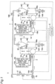
- Fig. 1 is a diagram showing a schematic configuration of an ion removing system 1 according to a first embodiment.
- the ion removing system 1 includes a primary-side flow path 2, a primary-side ion removing apparatus 3, a primary-side separating apparatus 4, a secondary-side ion removing apparatus 5, and a secondary-side separating apparatus 6, and a secondary-side flow path 7.
- the primary-side flow path 2 is connected to the primary-side ion removing apparatus 3.
- the primary-side flow path 2 is a flow path for supplying hard water to the primary-side ion removing apparatus 3.
- a pump P1 is disposed in a connecting portion between the primary-side flow path 2 and the primary-side ion removing apparatus 3.
- the pump P functions to cause the hard water flowing through the primary-side flow path 2 to flow through the primary-side ion removing apparatus 3 to the primary-side separating apparatus 4.
- the drive of the pump P1 is controlled by a controller 8.
- the primary-side ion removing apparatus 3 includes a primary-side hard water storage part 3A storing hard water, and a primary-side fine bubble generating part 3B generating and supplying fine bubbles to the primary-side hard water storage part 3A.
- the primary-side ion removing apparatus 3 is an apparatus causing fine bubbles to adsorb first metal ions in hard water in the primary-side hard water storage part 3A and thereby removing the first metal ions from the hard water.
- the primary-side fine bubble generating part 3B is disposed downstream of the pump P1 in the flow direction of the hard water so as to prevent gas from entering the pump P1.
- the metal ions are calcium ions (Ca 2+ ).
- the fine bubbles are bubbles having a diameter of 100 ⁇ m or less in a proportion of 90 % or more.
- the fine bubbles include microbubbles (e.g., having a diameter of 1 ⁇ m to 100 ⁇ m) and nanobubbles (e.g., having a diameter of less than 1 ⁇ m).
- the microbubbles may be bubbles recognizable as those having a bubble diameter on the order of micrometers by those skilled in the field of water treatment.
- the nanobubbles may be bubbles recognizable as those having a bubble diameter on the order of nanometers by those skilled in the field of water treatment.
- the fine bubbles have properties different from ordinary bubbles, such as long retention time in water, each of bubbles hardly increasing in diameter and less likely to combine with other bubbles, and a large contact area facilitating a chemical reaction.
- the fine bubbles may include bubbles having a diameter of 100 ⁇ m or more (such as milli-bubbles) in a small proportion. Bubbles having a diameter of 100 ⁇ m or less in a proportion of 90 % or more are defined as the fine bubbles. Additionally, conditions such as having a diameter of 60 ⁇ m or less in a proportion of 50 % or more and having a diameter of 20 ⁇ m or less in a proportion of 5 % or more may be added.
- the diameter of bubbles bubble diameter
- hard water containing fine bubbles may directly be photographed by a high-speed camera, and the bubble diameter may be calculated by a three-point method through image processing or may be measured by any other method.
- the timing of measuring the bubble diameter may be any timing as long as the fine bubbles are retained at the time. Examples of conditions of the measuring method using a high-speed camera described above are as follows.
- a first metal ion removal gas supply part 9A and a first metal solubilizer supply part 10A are connected via a primary-side gas switching mechanism 11A to the primary-side fine bubble generating part 3B.
- the first metal ion removal gas supply part 9A is configured to supply a first metal ion removal gas for removing the first metal ions in hard water to the primary-side fine bubble generating part 3B.
- the first metal ion removal gas supply part 9A is configured to supply "air" as the first metal ion removal gas to the primary-side fine bubble generating part 3B.
- the first metal ion removal gas supply part 9A may include a tank filled with the first metal ion removal gas, for example.
- the first metal ion removal gas supply part 9A may be an apparatus generating the first metal ion removal gas.
- the first metal ion removal gas supply part 9A may be an apparatus connected to a first metal ion removal gas supply source.
- the first metal solubilizer supply part 10A is configured to supply a first metal dissolution gas, which is an example of a first metal solubilizer dissolving crystals of a metal component deposited by crystallizing the first metal ions removed from the hard water, to the primary-side fine bubble generating part 3B.
- the first metal solubilizer supply part 10A is configured to supply "carbon dioxide (CO2)" as the first metal dissolution gas to the primary-side fine bubble generating part 3B.
- the first metal solubilizer supply part 10A is disposed upstream of the primary-side separating apparatus 4 in the flow direction of the hard water so that the first metal solubilizer can be supplied to the primary-side separating apparatus 4.
- the first metal solubilizer supply part 10A may include a tank filled with the first metal solubilizer, for example.
- the first metal solubilizer supply part 10A may be an apparatus generating the first metal solubilizer.
- the first metal solubilizer supply part 10A may be an apparatus connected to a first metal solubilizer supply source.
- the primary-side gas switching mechanism 11A is a mechanism switched to supply either the first metal ion removal gas or the first metal dissolution gas to the primary-side fine bubble generating part 3B. By switching the primary-side gas switching mechanism 11A, a softening treatment with the first metal ion removal gas and a regeneration treatment with the first metal dissolution gas can selectively be performed.
- the primary-side gas switching mechanism 11A is made up of one or more valves, for example. The switching operation of the primary-side gas switching mechanism 11A is controlled by the controller 8.
- the primary-side fine bubble generating part 3B When the primary-side gas switching mechanism 11A is switched to supply the first metal ion removal gas, the primary-side fine bubble generating part 3B generates the fine bubbles containing the first metal ion removal gas.
- the fine bubbles remove the first metal ions from the hard water and separate the crystals of the metal component, and the hard water is thereby subjected to the softening treatment.
- the principle of the softening treatment will be described in detail later.
- the primary-side fine bubble generating part 3B when the primary-side gas switching mechanism 11A is switched to supply the first metal dissolution gas, the primary-side fine bubble generating part 3B generates the fine bubbles containing the first metal dissolution gas.
- the fine bubbles can dissolve the crystals of the metal component adhering to the primary-side separating apparatus 4 to perform the regeneration treatment as described later. The principle of the regeneration treatment will be described in detail later.
- the primary-side separating apparatus 4 is connected to the primary-side ion removing apparatus 3 via a connection flow path 3C disposed on an upper outer circumferential portion of the primary-side hard water storage part 3A.
- the primary-side separating apparatus 4 is an apparatus separating the crystals of the metal component deposited by crystallizing the first metal ions removed from the hard water by the primary-side ion removing apparatus 3.
- the primary-side ion removing apparatus 3 and the primary-side separating apparatus 4 can reduce the concentration (hardness) of the first metal ions in the hard water to a predetermined concentration or less.
- the primary-side separating apparatus 4 is a cyclone-type centrifugal separating apparatus having a tapered inner circumferential surface 4Aa with a diameter decreasing downward and causing hard water to spirally flow downward along the inner circumferential surface 4Aa so that the crystals of the metal component are separated.
- the primary-side separating apparatus 4 includes a separating part 4A having the inner circumferential surface 4Aa and a crystal storage part 4B storing crystals of a metal component.
- connection flow path 3C is connected to the separating part 4A such that water having passed through the primary-side ion removing apparatus 3 is discharged in a direction eccentric from a central axis of the separating part 4A.
- Such an eccentric arrangement allows the water discharged into the separating part 4A to flow spirally downward along the inner circumferential surface 4Aa.
- the first metal ions having a large specific gravity removed from the hard water move toward the inner circumferential surface 4Aa due to centrifugal separation and are deposited as the crystals of the metal component in the vicinity of the inner circumferential surface 4Aa. A portion of the crystals adheres to the inner circumferential surface 4Aa.
- the crystal storage part 4B is disposed below the separating part 4A.
- the crystal storage part 4B includes a discharge flow path 4Ba for discharging water containing the crystals of the metal component.
- the discharge flow path 4Ba is provided with an opening/closing valve 12A capable of opening and closing the discharge flow path 4Ba.
- the opening/closing operation of the opening/closing valve 12A is controlled by the controller 8.
- a discharge-side backflow prevention mechanism 13A is disposed on the discharge flow path 4Ba downstream of the opening/closing valve 12A in a discharge direction.
- the discharge-side backflow prevention mechanism 13A is a mechanism preventing the crystals of the metal component from flowing back into the separating apparatus 4.
- the discharge-side backflow prevention mechanism 13A can prevent the crystals of the metal component from mixing again into treated water (soft water) obtained by separating the crystal of the metal component from hard water.
- the discharge-side backflow prevention mechanism 13A is made up of one or more check valves, for example.
- the discharge-side backflow prevention mechanism 13A may be made up of a vacuum breaker, for example.
- the discharge-side backflow prevention mechanism 13A may be configured to prevent backflow by a spout space disposed at an outlet of the discharge flow path 4Ba.
- the separating part 4A of the primary-side separating apparatus 4 is connected to the secondary-side ion removing apparatus 5 via a connection flow path 14.
- the connection flow path 14 is a flow path for taking out from the primary-side separating apparatus 4 the treated water obtained by separating the crystals of the metal component.
- the primary-side separating apparatus 4 is a cyclone-type centrifugal separating apparatus, the crystals of the metal component can be concentrated in the vicinity of the inner circumferential surface 4Aa.
- the connection flow path 14 is connected to an upper central portion of the separating part 4A at a position distant from the inner circumferential surface 4Aa.
- the connection flow path 14 is provided with a secondary-side pH adjustment apparatus 15B increasing the pH of the hard water from which the first metal ions are removed by the primary-side ion removing apparatus 3.
- the secondary-side pH adjustment apparatus 15B includes a secondary-side degassing apparatus removing carbon dioxide contained in the hard water from which the first metal ions are removed by the primary-side ion removing apparatus 3.
- the secondary-side pH adjustment apparatus 15B is configured to remove carbon dioxide contained in the hard water by spraying the hard water in a mist form in the air. The principle of increase in pH of hard water due to removal of carbon dioxide will be described later in detail.
- the drive of the secondary-side pH adjustment apparatus 15B is controlled by the controller 8.
- connection flow path 14 is connected to the secondary-side ion removing apparatus 5.
- the connection flow path 14 is a flow path for supplying the secondary-side ion removing apparatus 5 with the hard water from which the first metal ions are removed.
- a pump P2 is disposed in a connecting portion between the connection flow path 14 and the secondary-side ion removing apparatus 5.
- the pump P2 functions to cause the hard water flowing through the connection flow path 14 to flow through the secondary-side ion removing apparatus 5 to the secondary-side separating apparatus 6.
- the drive of the pump P2 is controlled by the controller 8.
- the secondary-side ion removing apparatus 5 includes a secondary-side hard water storage part 5A storing the hard water having the pH increased by the secondary-side pH adjustment apparatus 15B and a secondary-side fine bubble generating part 5B generating and supplying fine bubbles to the secondary-side hard water storage part 5A.
- the secondary-side ion removing apparatus 5 is an apparatus causing fine bubbles to adsorb second metal ions in the hard water in the secondary-side hard water storage part 5A and thereby removing the second metal ions from the hard water.
- the secondary-side fine bubble generating part 5B is disposed downstream of the pump P2 in the flow direction of the hard water so as to prevent gas from entering the pump P2.
- the second metal ions are magnesium ions (Mg 2+ ).
- a second metal ion removal gas supply part 9B and a second metal solubilizer supply part 10B are connected via a secondary-side gas switching mechanism 11B to the secondary-side fine bubble generating part 5B.
- the second metal ion removal gas supply part 9B is configured to supply a second metal ion removal gas for removing the second metal ions in the hard water to the secondary-side fine bubble generating part 5B.
- the second metal ion removal gas supply part 9B is configured to supply "air" as the second metal ion removal gas to the secondary-side fine bubble generating part 5B.
- the second metal ion removal gas supply part 9B may include a tank filled with the second metal ion removal gas, for example.
- the second metal ion removal gas supply part 9B may be an apparatus generating the second metal ion removal gas.
- the second metal ion removal gas supply part 9B may be an apparatus connected to a second metal ion removal gas supply source.
- the second metal solubilizer supply part 10B is configured to supply a second metal dissolution gas, which is an example of a second metal solubilizer dissolving crystals of a metal component deposited by crystallizing the second metal ions removed from the hard water, to the secondary-side fine bubble generating part 5B.
- the second metal solubilizer supply part 10B is configured to supply "carbon dioxide (CO 2 )" as the second metal dissolution gas to the secondary-side fine bubble generating part 5B.
- the second metal solubilizer supply part 10B is arranged upstream of the secondary-side separating apparatus 6 in the flow direction of the hard water so that the second metal solubilizer can be supplied to the secondary-side separating apparatus 6.
- the second metal solubilizer supply part 10B may include a tank filled with the second metal solubilizer, for example.
- the second metal solubilizer supply part 10B may be an apparatus generating the second metal solubilizer.
- the second metal solubilizer supply part 10B may be an apparatus connected to a second metal solubilizer supply source.
- the secondary-side gas switching mechanism 11B is a mechanism switched to supply either the second metal ion removal gas or the second metal dissolution gas to the secondary-side fine bubble generating part 5B. By switching the secondary-side gas switching mechanism 11B, a softening treatment with the second metal ion removal gas and a regeneration treatment with the second metal dissolution gas can selectively be performed.
- the secondary-side gas switching mechanism 11B is made up of one or more valves, for example. The switching operation of the secondary-side gas switching mechanism 11B is controlled by the controller 8.
- the secondary-side fine bubble generating part 5B When the secondary-side gas switching mechanism 11B is switched to supply the second metal ion removal gas, the secondary-side fine bubble generating part 5B generates the fine bubbles containing the second metal ion removal gas. The fine bubbles remove the second metal ions from the hard water and separate the crystals of the metal component, and the hard water is thereby subjected to the softening treatment.
- the secondary-side fine bubble generating part 5B when the secondary-side gas switching mechanism 11B is switched to supply the second metal dissolution gas, the secondary-side fine bubble generating part 5B generates the fine bubbles containing the second metal dissolution gas.
- the fine bubbles can dissolve the crystals of the metal component adhering to the secondary-side separating apparatus 6 to perform the regeneration treatment as described later.
- the secondary-side separating apparatus 6 is connected to the secondary-side ion removing apparatus 5 via a connection flow path 5C disposed on an upper outer circumferential portion of the secondary-side hard water storage part 5A.
- the secondary-side separating apparatus 6 is an apparatus separating the crystals of the metal component deposited by crystallizing the second metal ions removed from the hard water by the secondary-side ion removing apparatus 5.
- the secondary-side ion removing apparatus 5 and the secondary-side separating apparatus 6 can reduce the concentration (hardness) of the second metal ions in the hard water to a predetermined concentration or less to produce soft water.
- the definition of hard water and soft water for example, the definition of WHO may be used.
- the soft water may be defined as water having a hardness of less than 120 mg/L
- the hard water may be defined as water having a hardness of 120 mg/L or more.
- the secondary-side separating apparatus 6 is a cyclone-type centrifugal separating apparatus having a tapered inner circumferential surface 6Aa with a diameter decreasing downward and causing hard water to spirally flow downward along the inner circumferential surface 6Aa so that the crystals of the metal component are separated.
- the secondary-side separating apparatus 6 includes a separating part 6A having the inner circumferential surface 6Aa and a crystal storage part 6B storing crystals of a metal component.
- connection flow path 5C is connected to the separating part 6A such that water having passed through the secondary-side ion removing apparatus 5 is discharged in a direction eccentric from a central axis of the separating part 6A.
- Such an eccentric arrangement allows the water discharged into the separating part 6A to flow spirally downward along the inner circumferential surface 6Aa.
- the second metal ions having a large specific gravity removed from the hard water move toward the inner circumferential surface 6Aa due to centrifugal separation and are deposited as the crystals of the metal component in the vicinity of the inner circumferential surface 6Aa. A portion of the crystals adheres to the inner circumferential surface 6Aa.
- the crystal storage part 6B is disposed below the separating part 6A.
- the crystal storage part 6B includes a discharge flow path 6Ba for discharging water containing the crystals of the metal component.
- the discharge flow path 6Ba is provided with an opening/closing valve 12B capable of opening and closing the discharge flow path 6Ba.
- the opening/closing operation of the opening/closing valve 12B is controlled by the controller 8.
- a discharge-side backflow prevention mechanism 13B is disposed on the discharge flow path 6Ba downstream of the opening/closing valve 12B in a discharge direction.
- the discharge-side backflow prevention mechanism 13B is a mechanism preventing the crystals of the metal component from flowing back into the secondary-side separating apparatus 6.
- the discharge-side backflow prevention mechanism 13B can prevent the crystals of the metal component from mixing again into treated water (soft water) obtained by separating the crystal of the metal component from hard water.
- the discharge-side backflow prevention mechanism 13B is made up of one or more check valves, for example.
- the discharge-side backflow prevention mechanism 13B may be made up of a vacuum breaker, for example.
- the discharge-side backflow prevention mechanism 13B may be configured to prevent backflow by a spout space disposed at an outlet of the discharge flow path 6Ba.
- the secondary-side flow path 7 is connected to the secondary-side separating apparatus 6.
- the secondary-side flow path 7 is a flow path for taking out from the secondary-side separating apparatus 6 the treated water obtained by separating the crystals of the metal component.
- the secondary-side separating apparatus 6 is a cyclone-type centrifugal separating apparatus, the crystals of the metal component can be concentrated in the vicinity of the inner circumferential surface 6Aa.
- the secondary-side connection flow path 7 is connected to an upper central portion of the separating part 6A at a position distant from the inner circumferential surface 6Aa.
- the primary-side flow path 2 is provided with a supply-side backflow prevention mechanism 16.
- the supply-side backflow prevention mechanism 16 is a mechanism preventing the fine bubbles and the treated water from flowing back to the hard water supply side.
- the supply-side backflow prevention mechanism 16 is made up of one or more check valves, for example.
- the ion removing system 1 includes a flow switching mechanism switching the flow direction of the hard water flowing through the primary-side flow path 2 to either the primary-side ion removing apparatus 3 or the bypass flow path 17. Since the flow switching mechanism can be switched to cause the hard water flowing through the primary-side flow path 2 to flow through the bypass flow path 17 to the secondary-side flow path 7, the hard water can be used even during maintenance. Even not during maintenance, the flow switching mechanism can be switched to selectively use the hard water and the treated water (soft water).
- the flow switching mechanism includes a first valve 18A capable of opening and closing the primary-side flow path 2, a second valve 18B capable of opening and closing the secondary-side flow path 7, and a third valve 18C capable of opening and closing the bypass flow path 17.
- the opening/closing operations of the first valve 18A, the second valve 18B, and the third valve 18C are controlled by the controller 8.
- the controller 8 is configured to selectively provide a first control of opening the first valve 18A and the second valve 18B and closing the third valve 18C, and a second control of closing the first valve 18A and the second valve 18B and opening the third valve 18C.
- the controller 8 provides the first control, the hard water flowing through the primary-side flow path 2 flows to the primary-side ion removing apparatus 3, the connection flow path 14, and the secondary-side ion removing apparatus 5 and is subjected to the softening treatment before flowing into the secondary-side flow path 7.
- the treated water soft water
- the controller 8 When the controller 8 provides the second control, the hard water flowing through the primary-side flow path 2 flows through the bypass flow path 17 into the secondary-side flow path 7. As a result, the hard water is discharged to the outlet of the secondary-side flow path 7. Therefore, the controller 8 can provide the first control or the second control to selectively discharge the hard water or the treated water (soft water) from the outlet of the secondary-side flow path 7.
- hard water contains at least H + (hydrogen ions), OH - (hydroxide ions), CO 2 (carbon dioxide), H 2 CO 3 (hydrogen carbonate), HCO 3 - (hydrogen carbonate ions), and H 2 O (water).
- H + hydrogen ions
- OH - hydrogen ions
- CO 2 carbon dioxide
- H 2 CO 3 hydrogen carbonate
- HCO 3 - hydrogen carbonate ions
- H 2 O water
- H 2 CO 3 in the hard water changes into CO 2 and H 2 O due to a buffering action.
- H 2 CO 3 in the hard water is reduced. This is represented by a specific chemical formula as in Formula 1 below. (Formula 1) H 2 CO 3 ⁇ CO 2 +H 2 O
- HCO 3 - in the hard water binds to H + due to a buffering action and changes into H 2 CO 3 .
- This is represented by a specific chemical formula as in Formula 2 below. (Formula 2) HCO 3 - +H + ⁇ H 2 CO 3
- first and second metal ions in the hard water can be adsorbed to the fine bubbles and that the adsorbed first and second metal ions can be crystallized to remove crystals of metal components from the hard water. More specifically, the principle will be described as follows. It is noted that the present disclosure is not bound to the specific principles described in the following sections (1), (2), (3), and (4).
- H + hydrogen ions
- OH - hydrogen ions
- the hard water has Ca 2+ and Mg 2+ present as the positively charged first and second metal ions.
- Ca 2+ has a positive charge and a higher ionization tendency than Mg 2+ and is therefore adsorbed in preference to Mg 2+ by OH - present on the surfaces of the fine bubbles due to an action of an intermolecular force (interionic interaction). Ca 2+ can be adsorbed to the fine bubbles in this way.
- H + repelling Ca 2+ is present on the surfaces of the fine bubbles, it is probable that OH - acts in preference to H + and adsorbs Ca 2+ .
- the adsorption of Ca 2+ is mainly performed in the primary-side ion removing apparatus 3.
- a reaction shown in Fig. 4 is promoted by supplying the fine bubbles containing air into the hard water.
- the fine bubbles supplied into the hard water hardly float to the surface, dissolve into the hard water, and therefore gradually shrink as shown in Fig. 4 due to an increase in surface tension.
- Ca 2+ is adsorbed on the surfaces of the fine bubbles. More specifically, Ca 2+ is present as calcium ions of soluble Ca(HCO 3 ) 2 (calcium hydrogencarbonate). As the fine bubbles gradually shrink, the dissolved concentration of Ca 2+ on the surfaces of the fine bubbles increases.
- CaCO 3 (calcium carbonate) is insoluble (water-insoluble) and is therefore deposited as crystals of a metal component. As a result, those dissolved as Ca 2+ of Ca(HCO 3 ) 2 are deposited as crystals of the metal component. By promoting such a reaction, CaCO 3 deposited by crystallizing Ca 2+ can be separated from the hard water. The crystallization of Ca 2+ is mainly performed in the separating part 4A of the primary-side separating apparatus 4.
- the separating apparatus 4 is a cyclone-type centrifugal separating apparatus
- the crystals of the metal component are deposited in the vicinity of the inner circumferential surface 4Aa of the separating part 4A and stored in the crystal storage part 4B.
- the crystals of the metal component stored in the crystal storage part 4B are discharged through the discharge flow path 4Ba by opening the opening/closing valve 12A.
- the pH of the hard water with Ca 2+ removed is increased by the secondary-side pH adjustment apparatus 15B.
- Positively charged Mg 2+ is present in the hard water with Ca 2+ removed.
- negatively charged OH - present on the surfaces of the fine bubbles increases.
- positively charged Mg 2+ is more easily adsorbed to the fine bubbles. Consequently, an amount of Mg 2+ adsorbed to the fine bubbles can be increased, and the crystallization of the metal ions can be promoted as described later.
- H + repelling Mg 2+ is present on the surfaces of the fine bubbles, it is probable that OH - acts in preference to H + and adsorbs Mg 2+ .
- the adsorption of Mg 2+ is mainly performed in the secondary-side ion removing apparatus 5.
- Mg 2+ is adsorbed on the surfaces of the fine bubbles. More specifically, Mg 2+ is present as magnesium ions of soluble Mg(HCO 3 ) 2 (magnesium hydrogen carbonate). As the fine bubbles gradually shrink, the dissolved concentration of Mg 2+ on the surfaces of the fine bubbles increases. The increase in the dissolved concentration results in a supersaturation state at a certain point, and Mg 2+ is crystallized and deposited. This is represented by a specific chemical formula as in Formula 4 below. (Formula 4) Mg(HCO 3 ) 2 ⁇ MgCO 3 +CO 2 +H 2 O
- MgCO 3 magnesium carbonate
- Mg(HCO 3 ) 2 a metal component that dissolved as Mg 2+ of Mg(HCO 3 ) 2 are deposited as crystals of the metal component.
- MgCO 3 deposited by crystallizing the second metal ions Mg 2+ can be separated from the hard water.
- the crystallization of Mg 2+ is mainly performed in the separating part 6A of the secondary-side separating apparatus 6.
- the softening treatment By performing the softening treatment, a portion of CaCO 3 deposited by crystallizing the first metal ions adheres to the inner circumferential surface 4Aa of the separating part 4A.
- the regeneration treatment is performed as a treatment for returning CaCO 3 to Ca(HCO 3 ) 2 .
- the primary-side fine bubble generating part 3B generates fine bubbles containing carbon dioxide, which is a gas different from that used during the softening treatment.
- the reaction generates soluble (water-soluble) Ca(HCO 3 ) 2 from insoluble CaCO 3 .
- Ca(HCO 3 ) 2 dissolves into water and moves to the crystal storage part 4B.
- the Ca(HCO 3 ) 2 having moved to the crystal storage part 4B is discharged through the discharge flow path 4Ba by opening the opening/closing valve 12A.
- the insoluble CaCO 3 adhering to the inner circumferential surface 4Aa of the separating part 4A can be discharged to the outside to restore the original state. Subsequently, the softening treatment described above can be performed again.
- the softening treatment By performing the softening treatment, a portion of MgCO 3 deposited by crystallizing the second metal ions adheres to the inner circumferential surface 6Aa of the separating part 6A.
- the regeneration treatment is performed as a treatment for returning MgCO 3 to Mg(HCO 3 ) 2 .
- the secondary-side fine bubble generating part 5B generates fine bubbles containing carbon dioxide, which is a gas different from that used during the softening treatment.
- the reaction generates soluble (water-soluble) Mg(HCO 3 ) 2 from insoluble MgCO 3 .
- Mg(HCO 3 ) 2 dissolves into water and moves to the crystal storage part 6B.
- the Mg(HCO 3 ) 2 having moved to the crystal storage part 6B is discharged through the discharge flow path 6Ba by opening the opening/closing valve 12B.
- the insoluble MgCO 3 adhering to the inner circumferential surface 6Aa of the separating part 6A can be discharged to the outside to restore the original state. Subsequently, the softening treatment described above can be performed again.
- the ion removing system 1 of the first embodiment removes the first and second metal ions from the hard water by using the fine bubbles and therefore can eliminate the need for a large amount of salt water required for regenerating the ion exchange resin. This can simplify the regeneration treatment to make the maintenance easier. Additionally, since regeneration wastewater containing salt water is not generated, soil pollution and a load on sewage treatment can be suppressed to improve environmental properties. Furthermore, concentration of sodium ions is not increased in treated water, so that the generated treated water can be used as drinking water.
- Fig. 6 is a graph schematically showing changes in pH and hardness of hard water flowing through the ion removing system 1 according to the first embodiment.
- the primary-side ion removing apparatus 3 removes the first metal ions from the hard water
- the hardness of the hard water decreases, and the pH also decreases.
- the pH of the hard water is increased (subjected to a pH treatment) by the secondary-side PH adjustment apparatus 15B.
- the hardness of the hard water slightly decreases due to an increase in the pH of the hard water.
- the secondary-side ion removing apparatus 5 removes the second metal ions from the hard water having the increased pH, the hardness of the hard water further decreases, and the pH of the hard water also decreases.
- the pH of the hard water with the first metal ions removed is increased by the secondary-side pH adjustment apparatus 15B to increase the power of adsorption of the second metal ions (e.g., magnesium ions) by the fine bubbles, so that the removal efficiency of the second metal ions can be improved.
- the second metal ions e.g., magnesium ions
- the pH may be increased to a level required for removing the second metal ions. This can prevent the pH of the hard water from having a value unsuitable for drinking water.
- the second metal ions are removed after the first metal ions are completely removed; however, in reality, when the first metal ions are removed, the second metal ions may also be removed. Additionally, the first metal ions may remain when the second metal ions are removed, so that both the first metal ions and the second metal ions may be removed.
- removing the first metal ions means “mainly removing the first metal ions”
- removing the second metal ions means “mainly removing the second metal ions”.
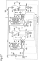
- Fig. 7 is a diagram showing a schematic configuration of an apparatus 90 used in Experimental Example 1.
- the apparatus 90 includes a water tank 91, a first piping 92, a pump 93, a second piping 94, and a mist nozzle 95.
- the water tank 91 is a water tank storing a hard water 96.
- the water tank 91 is connected to the pump 93 via the first piping 92.
- the pump 93 is connected to the mist nozzle 95 via the second piping 94.
- the mist nozzle 95 is disposed at a position separated upward from a sample 97 by a mist distance H1.
- the pump 93 is a pump pumping the hard water 96 to the mist nozzle 95.
- the mist nozzle 95 is a nozzle spraying the hard water supplied via the second piping 94 toward the sample 97 in a mist form. Remaining water remaining in the water tank 91 is drained to the outside by opening an opening/closing valve 98 disposed in the first piping 92.
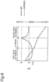
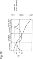
- Fig. 8 is a graph showing results of Experimental Example 1.
- the nozzle 1 is a nozzle spraying a mist having a mist diameter of 290 ⁇ m at an instantaneous flow rate of 1.3 L/min.
- the nozzle 2 is a nozzle spraying a mist having a mist diameter of 760 ⁇ m at an instantaneous flow rate of 4.2 L/min.
- the nozzle 3 is a nozzle spraying a mist having a mist diameter of 2500 ⁇ m at an instantaneous flow rate of 0.2 L/min.
- the horizontal axis represents the mist distance H1 (mm), and the vertical axis represents the pH of the hard water 96.
- the mist diameter becomes smaller, i.e., as the specific surface area becomes larger, the pH of the hard water 96 is more increased.
- the pH of the hard water 96 is basically increased since the contact time of the hard water 96 with the air becomes longer.
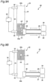
- Figs. 9A and 9B are diagrams showing a schematic configuration of the apparatus 20 used in Experimental Example 2.
- Fig. 9A shows a state after a predetermined time has elapsed (specifically, after 15 seconds have elapsed) from generation of fine bubbles
- Fig. 9B shows a state after a predetermined time has further elapsed (specifically, after 45 seconds have elapsed) from the state shown in Fig. 9A
- the state of Fig. 9A corresponds to a state when the elapsed time from the generation of fine bubbles is 15 seconds in Fig. 10
- the state of Fig. 9B corresponds to a state when the elapsed time from the generation of fine bubbles is 60 seconds in Fig. 10 .
- the apparatus 20 shown in Figs. 9A and 9B is an experimental apparatus capable of supplying fine bubbles 23 from the bottom surface side in a water tank 22 (hard water storage part) storing a hard water 21.
- the concentration of metal ions in the hard water 21 can be measured at two positions on the bottom surface side and the water surface side.
- the apparatus 20 includes the water tank 22, a gas supply part 24, a first piping 25, a fine bubble generating part 26, a second piping 27, a pump 28, a first water intake part 30, a second water intake part 32, and a metal ion concentration detector 34.
- the water tank 22 is a water tank storing the hard water 21.
- the water tank 22 is configured as a tank elongated in a vertical direction.
- the gas supply part 24 is a member supplying a gas to the fine bubble generating part 26 via the first piping 25.
- the fine bubble generating part 26 is an apparatus generating the fine bubbles 23 from the gas supplied from the gas supply part 24.
- the fine bubble generating part 26 corresponds to the primary-side fine bubble generating part 3B and the secondary-side fine bubble generating part 5B described above.
- the gas is supplied from the gas supply part 24 to the fine bubble generating part 26 due to an action of negative pressure from the pump 28 via the second piping 27.
- the first water intake part 30 is a member taking sample water of the hard water 21 from near a bottom surface 22a of the water tank 22.
- the second water intake part 32 is a member taking sample water from near a water surface 22b of the water tank 22.
- the height positions of the first water intake part 30 and the second water intake part 32 may be set to any positions, and a distance D1 from the first water intake part 30 to the second water intake part 32 can be adjusted to a desired value.
- the height position of the first water intake part 30 is set to substantially the same position as the height position where the fine bubble generating part 26 generates the fine bubbles 23.
- the metal ion concentration detector 34 is a member detecting the concentration of metal ions in the sample water taken from the first water intake part 30 and the second water intake part 32.
- the gas is sent from the gas supply part 24 via the first piping 25 to the fine bubble generating part 26 due to the action of negative pressure from the pump 28 via the second piping 27.
- the fine bubble generating part 26 uses this gas as a raw material to generate and supply the fine bubbles 23 to the water tank 22 (arrow A1 of Fig. 9A ).
- the fine bubble generating part 26 and the pump 28 are operated for a predetermined period (15 seconds in Experimental Example 2) to continuously generate the fine bubble 23.
- the sample water was extracted from the first water intake part 30 and the second water intake part 32 at a predetermined timing during the operation to measure the metal ion concentration with the metal ion concentration detector 34, and the results are shown in Fig. 6 .
- the horizontal axis represents an elapsed time (seconds) from the generation of fine bubbles
- the vertical axis represents a concentration transition (%) of metal ions (Ca 2+ ) detected by the metal ion concentration detector 34.
- the concentration transition of the metal ions represents the transition of the metal ion concentration when the metal ion concentration measured at the start of operation is 100 %.
- the concentration in the sample water extracted from the first water intake part 30 near the bottom surface 22a of the water tank 22 increases to about 108 % when 15 seconds have elapsed. During the subsequent resting period, the concentration gradually decreases and finally decreases to about 97 %.
- the concentration in the sample water extracted from the second water intake part 32 near the water surface 22b of the water tank 22 is maintained at nearly 100 % until 15 seconds have elapsed, then gradually increases during the resting period, and finally increases to about 115 %.
- the metal ion concentration is increased in the sample water of the first water intake part 30 in which the fine bubbles 23 are retained.
- the metal ion concentration is almost not changed in the sample water of the second water intake part 32 in which the fine bubbles 23 are not retained.
- the metal ion concentration is reduced to a little less than 100 % in the sample water of the first water intake part 30 in which the fine bubbles 23 are not retained.
- the metal ion concentration is significantly increased in the sample water of the second water intake part 32 in which the fine bubbles 23 are retained.
- the second embodiment is different from the first embodiment in that nitrogen is used instead of air as the gas of the fine bubbles in the softening treatment.
- the number of H + ions is reduced relative to the number of OH - ions by promoting the reaction of Formula 7.
- a negative charge becomes strong in terms of the fine bubbles, so that Ca 2+ or Mg 2+ having a positive charge is easily adsorbed.
- the reaction of Formula 7 can be promoted as compared to when air is used as in the first embodiment, so that the adsorption of the first and second metal ions is further promoted. As a result, the first and second metal ions can be separated and removed in larger amount from hard water.
- the principle is presumed to be applicable not only to nitrogen but also to any gas that can react with H + ions to reduce the number of H + ions relative to the number of OH - ions.
- nitrogen is an inert gas different from air
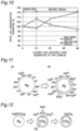
- balance of partial pressure is lost in the gas contained in the hard water. This promotes a reaction as shown in Fig. 12 .
- reaction occurs such that insoluble CaCO 3 is generated from soluble Ca(HCO 3 ) 2 .
- a reaction also occurs such that insoluble MgCO 3 is generated from soluble Mg(HCO 3 ) 2 .
- CO 2 and H 2 O are generated.
- CaCO 3 and MgCO 3 are insoluble and are thereof deposited as crystals of metal components.
- the first metal ions contained as Ca 2+ of Ca(HCO 3 ) 2 and the second metal ions contained as Mg 2+ of Mg(HCO 3 ) 2 in the hard water can be crystallized and deposited by the reactions. As a result, the crystals of the metal components can be removed from the hard water.
- the principle is presumed to be applicable not only to nitrogen but also to any gas other than air that can break the balance of partial pressure of the gas dissolved in hard water.
- the reactions described in the sections (5) and (6) can be promoted as compared to when air is used. This can improve the accuracy of removal of the first and second metal ions from the hard water.
- the secondary-side pH adjustment apparatus 15B is configured to remove carbon dioxide contained in the hard water by spraying the hard water in a mist form in the air; however, the present disclosure is not limited thereto.
- the secondary-side pH adjustment apparatus 15B may be configured to remove carbon dioxide contained in the hard water by spraying the hard water in a mist form in a nitrogen atmosphere.
- carbon dioxide in the hard water acts to replace nitrogen, so that carbon dioxide is easily released from the hard water. This can improve the carbon dioxide removal efficiency.
- the secondary-side pH adjustment apparatus 15B may be configured to remove carbon dioxide contained in the hard water, for example, by supplying a gas into the hard water for bubbling.
- a gas having a low carbon dioxide concentration for example, air.
- a gas containing no carbon dioxide for example, nitrogen, as the gas.
- nitrogen in bubbles generated by bubbling in the hard water acts to replace nitrogen, so that carbon dioxide is easily released from the hard water. This can improve the carbon dioxide removal efficiency.
- the bubbles generated in the hard water by bubbling may have a larger average outer diameter than the fine bubbles generated by the primary-side fine bubble generating part 3B and the secondary-side fine bubble generating part 5B.
- the bubbles generated in the hard water by bubbling may be milli-bubbles (having a diameter of 1 mm or more and 10 mm or less).
- the milli-bubbles may be bubbles recognizable as those having a bubble diameter on the order of millimeters by those skilled in the field of water treatment.
- a ratio of bubbles in hard water can be increased (e.g., from several % to 50 %) to increase the specific surface area of the bubbles, and the effect of removing carbon dioxide contained in the hard water can be improved.
- Examples of a method for removing carbon dioxide contained in hard water include a membrane degassing method, a vacuum degassing method, and a heating degassing method, in addition to the stripping method of spraying a mist and the bubbling method described above.
- Carbon dioxide contained in hard water may be removed by using an apparatus using these degassing methods.
- the apparatus using the stripping or bubbling method described above can remove carbon dioxide contained in hard water with a relatively simple structure.
- a method for removing metal ions by an ion removing system according to a third embodiment of the present disclosure will be described.
- differences from the first and second embodiments will mainly be described, and the description overlapping with the first and second embodiments will not be made.
- the third embodiment is different from the first and second embodiments in that fine bubbles containing a mixed gas obtained by mixing multiple types of gases are generated.
- the mixed gas used for generating the fine bubbles in the third embodiment is a gas obtained by mixing two types of gases, i.e., a first gas that is a basic gas and a second gas that is a gas having a property of slower dissolution rate than the first gas. Therefore, the first metal ion removal gas supply part 9A shown in Fig. 1 supplies the mixed gas obtained by mixing the first gas and the second gas, as the first metal ion removal gas to the primary-side fine bubble generating part 3B.
- the second metal ion removal gas supply part 9B shown in Fig. 1 supplies the mixed gas obtained by mixing the first gas and the second gas, as the second metal ion removal gas to the secondary-side fine bubble generating part 5B.
- the first gas contained in the mixed gas is a basic gas receiving H + in an acid-base reaction.
- the first gas dissolves in water to generate OH - .
- the reaction of Formula 9-1 occurs.
- the first gas is represented by Chemical Formula X.
- the reaction of Formula 9-1 occurs, as shown in Fig. 14 , the proportion of OH - present around fine bubbles 40 increases as compared to the proportion of H + (H + is not shown in Fig. 14 ).
- a potential of a solid-liquid interface strongly depends on pH in water quality since H + and OH- in water are potential-determining ions, and a positive charge becomes stronger as H + increases while a negative charge becomes stronger as OH - increases.
- a negative charge becomes strong in terms of the fine bubbles 40, so that Ca 2+ or Mg 2+ having a positive charge is easily adsorbed. In this way, the first and second metal ion adsorption effect of the fine bubbles 40 can be improved.
- the basic gas of ammonia is used as the first gas.
- Formula 9-1 is specifically described as in Formula 10. (Formula 10) NH 3 +H 2 O ⁇ NH 4 + +OH -
- the generation cost of the fine bubbles 40 can be reduced while the first and second metal ion adsorption effect described above is improved.
- the principle is presumed to be applicable not only to ammonia but also to any basic gas.
- a basic gas include methylamine, ethylamine, propylamine, isopropylamine, butylamine, hexylamine, cyclohexylamine, dimethylamine, diethylamine, diisopropylamine, dipropylamine, di-n-butylamine, ethanolamine, diethylethanolamine, dimethylethanolamine, ethylenediamine, dimethylaminopropylamine, N,N-dimethylethylamine, trimethylamine, triethylamine, tetramethylenediamine, diethylenetriamine, propyleneimine, pentamethylenediamine, hexamethylenediamine, morpholine, N-methylmorpholine, and N-ethylmorpholine.
- X is not limited to a basic gas, and it is probable that the same effect is produced as long as X is a "hydroxyl ion donating gas" reacting with water (H 2 O) to donate a hydroxyl ion (OH - ).
- the hydroxyl ion donating gas include a soluble ozone gas (O 3 ).
- O 3 soluble ozone gas
- the first gas is the basic gas contained in the mixed gas and dissolves in water to increase the proportion of OH- on the surfaces of the fine bubbles 40.
- Such a first gas is mixed with the second gas that is a gas having a property of slower dissolution rate than the first gas.
- the fine bubbles 40 are prevented from being entirely dissolved in water even when the first gas is dissolved in water, so that the state of the fine bubbles 40 can be maintained.
- the adsorption effect on Ca 2+ or Mg 2+ ions attributable to the fine bubbles described in the first and second embodiments can be maintained.
- nitrogen is used as the second gas.
- nitrogen which is a versatile gas harmless to the human body, the generation cost of the fine bubbles 40 can be reduced while safety is secured.
- nitrogen is a non-water-soluble gas (non-soluble gas), the effect of maintaining the state of the fine bubbles 40 can more effectively be exerted.
- a gas to be selected may be a gas having a rate of dissolution (solubility) into water slower (lower) than the first gas under the same conditions including temperature and pressure conditions.
- a second gas include nitrogen, hydrogen, carbon monoxide, butane, oxygen, methane, propane, ethane, nitric oxide, ethylene, propene, acetylene, and carbon dioxide in ascending order of solubility.
- a non-water-soluble gas such as nitric oxide, oxygen, or hydrogen is used, the effect of maintaining the state of the fine bubbles 40 can more effectively be exerted.
- the fine bubble generating part of the third embodiment generates the fine bubbles 40 from a mixed gas obtained by mixing the first gas reacting with water to donate hydroxyl ions and the second gas having a property of slower dissolution rate than the first gas.
- the first gas is a hydroxyl ion donating gas and reacts with water to increase the proportion of OH - on the surfaces of the fine bubbles 40. This can increase the effect of adsorbing metal ions such as Ca 2+ to the fine bubbles 40.
- the second gas having a property of slower dissolution rate than the first gas the fine bubbles 40 can be prevented from being completely dissolved in water to maintain the state of the fine bubbles 40.
- the first gas is a soluble basic gas (ammonia). Since the first gas is a basic gas and is first dissolved in water, and the second gas having a property of slower dissolution rate than the basic gas is negatively charged, the effect can be achieved by utilizing a difference in dissolution rate between the two gases.
- Mixing proportions of ammonia and nitrogen in the fine bubbles 40 may be set to any value or may be set, for example, such that the mixing proportion of nitrogen to ammonia becomes larger (e.g., ammonia:nitrogen is 1:99 in an amount of substance (volume ratio)).
- the increase in OH - due to the dissolution of ammonia is limited only in a region near the surfaces of the fine bubbles 40, and the proportion of OH - hardly changes at a position distant from the fine bubbles 40. This can keep the water quality of the entire water unchanged while causing a change only in the vicinity of the surfaces of the fine bubbles 40.
- the proportion of nitrogen the state of the fine bubbles 40 can be maintained longer.
- the effect described above can be produced by setting the amount of substance of the second gas, which has a slower dissolution rate than the basic gas, larger than the amount of substance of the first gas, which is the basic gas, in the mixed gas. Since the amount of substance and the volume are proportional to each other under the conditions of the same temperature and the same pressure, the mixing proportions of the first gas and the second gas may be set by using either the amount of substance or the volume.
- the mixing proportions may be set such that the mixing proportion of ammonia to nitrogen becomes larger With such a setting, the first and second metal ions contained in hard water can further be crystallized and removed.
- the principle of promotion of crystallization as described above will be described in Experimental Examples 3 to 5.
- the fine bubbles 40 of the mixed gas obtained by mixing ammonia and nitrogen are supplied to hard water.
- Such a supply form can prevent ammonia from being dissolved alone at a position distant from the fine bubbles 40, so that the function of increasing OH - only in the vicinity of the surfaces of the fine bubbles 40 can sufficiently be exerted.
- the concentration of OH- on the surfaces of the fine bubbles 40 is maximized. Specifically, the pH on the surfaces of the fine bubbles 40 is maximized, and the zeta potential of the fine bubbles 40 is maximized (large local pH, large zeta potential).
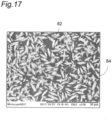
- crystallization of Ca 2+ or Mg 2+ adsorbed to the surfaces of the fine bubbles 40 starts. Specifically, Ca 2+ or Mg 2+ is crystallized and deposited as crystals 42. Additionally, as the crystals 42 are deposited, the fine bubbles 40 starts disappearing (disappearance).
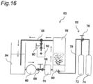
- Fig. 16 is a diagram showing a schematic configuration of the apparatus 50 used in Experimental Examples 3 to 5.
- the apparatus 50 shown in Fig. 16 includes a mixed gas supply part 52, a treatment tank 54, a first piping 56, a second piping 58, a water sampling valve 60, a water sampler 62, a water storage tank 64, a pump 66, a flow rate adjustment valve 68, and a flowmeter 70.
- the mixed gas supply part 52 is a member supplying the mixed gas to the treatment tank 54.
- the mixed gas supply part 52 includes an ammonia supply source 72, a nitrogen supply source 74, a mixing ratio adjustment valve 76, a supply piping 78, and a fine bubble generating part 80.
- the mixed gas supply part 52 uses the ammonia supply source 72 and the nitrogen supply source 74 to generate the mixed gas obtained by mixing ammonia (the first gas) and nitrogen (the second gas).
- the mixing proportions of ammonia and nitrogen can be set to any ratio by the mixing ratio adjustment valve 76.
- the mixed gas is supplied through the supply piping 78 to the fine bubble generating part 80 disposed in a bottom portion of the treatment tank 54.
- the fine bubble generating part 80 is a member forming fine bubbles of the mixed gas.
- the treatment tank 54 is a tank (hard water storage part) storing hard water as treated water to be treated.
- the metal component is removed, or particularly, crystallized, from the hard water, in accordance with the principle described in the third embodiment.
- the treated water after treatment is sent to the first piping 56.
- the water sampling valve 60 is disposed in the middle of the first piping 56. By opening and closing the water sampling valve 60, the treated water passing through the first piping 56 is sampled. The sampled treated water is put into the water sampler 62.
- the first piping 56 is connected to the water storage tank 64.
- the water storage tank 64 is a tank storing the treated water.
- the treated water stored in the water storage tank 64 is returned through the second piping 58 to the treatment tank 54. As a result, the treated water is circulated.
- the pump 66, the flow rate adjustment valve 68, and the flowmeter 70 are attached to the second piping 58.
- the pump 66 is a member generating a propulsive force causing the treated water in the water storage tank 64 to flow through the second piping 58.
- the flow rate adjustment valve 68 is a valve adjusting the flow rate of the treated water passing through the second piping 58.
- the flowmeter 70 is a device measuring the flow rate of the treated water flowing through the second piping 58.
- the apparatus 50 as described above was used for performing a treatment of removing the metal component in the hard water in the treatment tank 54 while continuously operating the pump 66 and for collecting the treated water after the treatment from the water sampler 62 to measure various parameters.
- a rate of crystallization of the metal component contained in the treated water was examined.
- the crystallization rate in this specification is not limited to a substance composed of atoms and molecules periodically arranged with regularity and means a rate of a substance simply deposited as a solid.
- the crystallization rate may be referred to as "deposition rate".
- Experimental Example 3 the apparatus 50 described above was used for collecting the treated water after the elapse of a predetermined time as sample water with the water sampler 62 while operating the pump 66 to cause the hard water to flow into the treatment tank 54.
- the mixing proportions of ammonia and nitrogen in the mixed gas were changed to examine differences in the crystallization rate at respective mixing proportions. Specific experimental conditions of Experimental Example 3 are listed below.
- the treated water supplied from the treatment tank 54 to the first piping 56 was discarded except the water collected with the water sampler 62 and was not supplied to the water storage tank 64.
- the crystallization rate increases as the mixing percentage of ammonia becomes higher. Particularly, when the mixing percentage of ammonia is 70 % or more, the crystallization rate dramatically increases.
- Figs. 18A and 18B it can be seen that when the mixing percentage of ammonia is higher, the pH is increased. It is noted that although the pH is increased, the maximum value is between 8.5 and 9.
- the pH reference value for tap water defined by the Ministry of Health, Labor and Welfare is in the range of 5.8 to 8.6, and it can be seen that even if the mixing percentage of ammonia is high, the pH varies to a value close to the range.
- the desirable drinkable range of alkali ion water prescribed in Pharmaceutical Affairs Law is pH 9 to 10. Since the pH value can be kept lower than this range, it can be seen that the water is suitable as drinking water.
- the factor preventing the pH from excessively increasing even at a high mixing percentage of ammonia is probably that the pH is mainly locally increased around the fine bubbles 40 as described above with reference to Fig. 15 , rather than increasing the pH of the entire treated water.
- Experimental Example 4 as in Experimental Example 3, the apparatus 50 described above was used for collecting the treated water after the elapse of a predetermined time as sample water with the water sampler 62 while operating the pump 66 to cause the hard water to flow into the treatment tank 54.
- Experimental Example 4 only two patterns of 70 % and 100 % were used for the mixing percentage of ammonia in the mixed gas.
- the sample water was collected at predetermined intervals from the start of operation of the pump 66 to measure various parameters.
- the treated water supplied from the treatment tank 54 to the first piping 56 was all returned to the water storage tank 64 to circulate the treated water except the water collected with the water sampler 62. Specific experimental conditions of Experimental Example 4 are listed below.
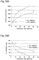
- the horizontal axis represents the operating time (minutes) of the pump 66, and the vertical axis represents the crystallization rate (%) of the sample water.
- the horizontal axis represents the operating time (minutes) of the pump 66, and the vertical axis represents the Ca hardness (mg/L) of the sample water.
- the horizontal axis represents the operating time (minutes) of the pump 66, and the vertical axis represents the pH of the sample water.
- the crystallization rate increases as the operating time elapses, regardless of whether the ammonia mixing percentage is 70 % or 100 %.
- the Ca hardness decreases as the operating time elapses. This reveals that the metal component Ca 2+ dissolved in the hard water is crystallized as CaCO 3 due to introduction of the fine bubbles using the mixed gas.
- the increase speed of the crystallization rate and the decrease speed of the Ca hardness are faster when the mixing percentage of ammonia is 100 % than when the mixing percentage is 70 %. This reveals that ammonia significantly contributes to the crystallization of Ca 2+ into CaCOs.
- the pH gradually increases as the operating time elapses, regardless of whether the mixing percentage of ammonia is 70 % or 100 %. No significant difference is observed in pH value between when the mixing percentage of ammonia is 70 % and when the mixing percentage is 100 %. Even when the operating time of 50 minutes has elapsed, the pH is between 9 and 10 and is not excessively increased.
- the factor moderating the increase speed of the pH in this way is probably that the pH is mainly locally increased around the fine bubbles 40 as described above with reference to Fig. 15 , rather than increasing the pH of the entire treated water.
- Experimental Example 5 as in Experimental Examples 3 and 4, the apparatus 50 described above was used for collecting the treated water after the elapse of a predetermined time as sample water with the water sampler 62 while operating the pump 66 to cause the hard water to flow into the treatment tank 54.
- the sample water was collected at predetermined intervals from the start of operation of the pump 66 to measure various parameters.
- the treated water supplied from the treatment tank 54 to the first piping 56 was all returned to the water storage tank 64 to circulate the treated water except the water collected with the water sampler 62.
- only one pattern of 70 % was used for the mixing percentage of ammonia in the mixed gas.
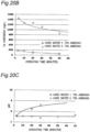
- the horizontal axis represents the operating time (minutes) of the pump 66, and the vertical axis represents the crystallization rate (%) of the sample water.
- the horizontal axis represents the operating time (minutes) of the pump 66, and the vertical axis represents the Ca hardness (mg/L) of the sample water.
- the horizontal axis represents the operating time (minutes) of the pump 66, and the vertical axis represents the pH of the sample water.
- Fig. 20D is a graph of Fig. 20B in which the total carbonic acid concentration (mg/L) is added to the vertical axis.
- Figs. 20A and 20C it can be seen that the increase speed of the crystallization rate and the increase speed of the pH are significantly different between the hard water 1 and the hard water 2. Specifically, it can be seen that the increase speed of the crystallization rate and the increase speed of the pH are higher in the hard water 1 than the hard water 2.
- the present inventors focused attention on "total carbonic acid concentration" and conducted a study based on data shown in Fig. 20D .
- the total carbonic acid concentration of the hard water 1 has a value of 150 to 200 mg/L when the operating time is 50 minutes. Therefore, the hard water 1 contains large amounts of HCO 3 - and CO 3 2- .
- the crystallization rate of the hard water 1 has reached 70 to 80 % as shown in Fig. 20A .
- the total carbonic acid concentration of the hard water 2 has value of about 20 mg/L when the operating time is 70 minutes.
- the crystallization rate of the hard water 2 is expected to be about 40 % when the operating time is 70 minutes.
- HCO 3 - and CO 3 2- function as components for crystallizing Ca 2+ as CaCOs. It is probable that the increase speed of the crystallization rate is higher in the hard water 1 than the hard water 2 since HCO 3 - and CO 3 2- are contained in larger amounts.
- Table 1 shows contents of metal components contained in the hard waters 1, 2 and the total carbonic acid concentration.
- the contents of Ca, Mg, and CO 3 2- per unit volume contained in the hard water 1, i.e., Evian (registered trademark), are 80, 26, and 357 mg/L, respectively.
- the contents of Ca, Mg, and CO 3 2- per unit volume contained in the hard water 2, i.e., Contrex (registered trademark), are 468, 74.8, and 372 mg/L. Therefore, the contents of CO 3 2- per unit volume contained in the hard water 1 and the hard water 2 are 357 mg/L and 372 mg/L, which are substantially the same.
- the amount of CO 3 2- required for dissolution of Ca and Mg relative to the contents of Ca and Mg contained in hard water is about 184 mg/L for the hard water 1 and about 887 mg/L for the hard water 2. Therefore, the hard water 1 has surplus of about 173 mg/L of the actually contained amount of CO 3 2- relative to the amount of CO 3 2- required for dissolution of Ca and Mg. This means that CO 3 2- for crystallizing Ca 2+ is abundantly present when the fine bubbles of the mixed gas are introduced.
- the hard water 2 is about 515 mg/L short of the actually contained amount of CO 3 2- relative to the amount of CO 3 2- required for dissolution of Ca and Mg. As a result, when the fine bubbles of the mixed gas are introduced, crystallization is probably not promoted due to short of CO 3 2- for crystallizing Ca 2+ .
- a carbonic acid gas may be introduced into the hard water before introducing the fine bubbles.
- a carbonic acid gas generating part generating a carbonic acid gas may further be included.
- a carbonic acid gas may be generated by the carbonic acid gas generating part and supplied into the hard water. This can probably promote the crystallization of the metal component in the hard water.
- the crystallization of the metal component can be promoted by setting the amount of substance of ammonia larger than the amount of substance of nitrogen in the mixed gas. Furthermore, by setting the mixing percentage of ammonia in the mixed gas to 70 % or more, the crystallization of the metal component can significantly be promoted.
- Experimental example 6 is a sensory evaluation experiment for evaluating "foaming" for the sample water (soft water) treated by using the apparatus 50 described above.
- the foaming is related to a foaming power according to height and size of foam generated from a water surface. It is generally considered that when an amount of hardness components is smaller, the foaming is larger, which is advantageous in that a washing effect is increased when the water is used for the purpose of washing, for example.
- the experimental method of Experimental Example 6 is based on the standard of "foaming": SHASE-S 218 of the Society of Heating, Air-Conditioning and Sanitary Engineers of Japan. Specifically, diluted water was prepared by diluting 1.5 g of pure soap with 200 ml of water, and 1 mL of the diluted water and 9 mL of treated water of interest were mixed and put into a measuring cylinder as 10 mL of evaluation water. COW BRAND Soap Red Box a1 (Cow Brand Soap Kyoshinsha Co.,Ltd.) was used for the pure soap, and distilled water of Autostill WG221 (Yamato Scientific Co., Ltd.) was used for 200 ml of water. The measuring cylinder was shaken 50 times, and a height of the foam from the water surface was measured after 1 minute.
- COW BRAND Soap Red Box a1 (Cow Brand Soap Kyoshinsha Co.,Ltd.) was used for the pure
- the "sample water” treated by using the apparatus 50 is improved in terms of foaming as compared to the hard water before treatment and achieves the foaming close to the "tap water” and the "pure water”.
- Experimental Example 7 the treated water (hard water) is treated by using the same apparatus 50 ( Fig. 16 ) as in Experimental Examples 3 to 5 to compare the crystallization rate of the treated sample water.
- Type of treated water (common): hard water 1
- the horizontal axis represents the time (minutes), and the vertical axis represents the crystallization rate (%) of the Ca hardness.
- the horizontal axis represents the time (minutes), and the vertical axis represents the crystallization rate (%) of the total hardness.
- the micro-bubbles achieve higher crystallization rates than the milli-bubbles for both the Ca hardness and the total hardness. Therefore, the crystallization rate is higher in the case of using the micro-bubbles, which are the fine bubbles, as compared to the case of using the milli-bubbles, which are not the fine bubbles, and this demonstrates the metal ion crystallization effect of the fine bubbles.
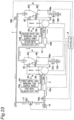
- Fig. 23 is a schematic of the ion removing system according to the fourth embodiment.
- the fourth embodiment is different from the first embodiment in that the primary-side flow path 2 is provided with a primary-side pH adjustment apparatus 15A.
- the primary-side pH adjustment apparatus 15A is an apparatus increasing the pH of the hard water contained in the primary-side hard water storage part 3A.
- the primary-side pH adjustment apparatus 15A includes a secondary-side degassing apparatus removing carbon dioxide contained in the hard water.
- the drive of the primary-side pH adjustment apparatus 15A is controlled by the controller 8.
- the primary-side pH adjustment apparatus 15A removes carbon dioxide from the hard water
- the pH of the hard water increases. Since the pH of the hard water increases, the hardness of the hard water slightly decreases.
- the primary-side ion removing apparatus 3 removes the first metal ions from the hard water
- the hardness of the hard water decreases, and the pH also decreases.
- the pH of the hard water is increased by the secondary-side pH adjustment apparatus 15B removing carbon dioxide from the hard water.
- the secondary-side ion removing apparatus 5 removes the second metal ions from the hard water having the increased pH, the hardness of the hard water further decreases, and the pH of the hard water decreases again.
- the pH of the hard water is increased by the primary-side pH adjustment apparatus 15A to increase a power of adsorption of the first metal ions by the fine bubbles, so that the removal efficiency of the first metal ions can be improved.
- the pH of the hard water with the first metal ions removed is increased by the secondary-side pH adjustment apparatus 15B to increase a power of adsorption of the second metal ions by the fine bubbles, so that the removal efficiency of the second metal ions can be improved.
- the pH of the hard water can be increased to 9 or more.
- the primary-side pH adjustment apparatus 15C may be an alkali ion water purifier having a known structure, for example.
- the drive of the primary-side pH adjustment apparatus 15C is controlled by the controller 8.
- the discharge flow path 15Ca is provided with an opening/closing valve 12C capable of opening and closing the discharge flow path 15Ca.
- the opening/closing operation of the opening/closing valve 12C is controlled by the controller 8.
- a discharge-side backflow prevention mechanism 13C is disposed on the discharge flow path 15Ca downstream of the opening/closing valve 12C in the discharge direction.
- the discharge-side backflow prevention mechanism 13C is a mechanism preventing the acidic water from flowing back into the primary-side pH adjustment apparatus 15C.
- the discharge-side backflow prevention mechanism 13C can prevent the acidic water from mixing again into the alkaline water separated from the hard water.
- the discharge-side backflow prevention mechanism 13C is made up of one or more check valves, for example.
- the secondary-side pH adjustment apparatus 15D is an apparatus increasing the pH of the hard water from which the first metal ions are removed by the primary-side ion removing apparatus 3.
- the secondary-side pH adjustment apparatus 15D includes a secondary-side electrolysis apparatus electrolyzing the hard water from which the first metal ions are removed by the primary-side ion removing apparatus 3, to generate acidic water and alkaline water.
- the secondary-side pH adjustment apparatus 15D is configured to supply the alkaline water as hard water having the increased pH to the secondary-side hard water storage part 5A.
- the secondary-side pH adjustment apparatus 15D includes a discharge flow path 15Da for discharging the acidic water electrolyzed from the hard water.
- the discharge flow path 15Da is provided with an opening/closing valve 12D capable of opening and closing the discharge flow path 15Da.
- the opening/closing operation of the opening/closing valve 12D is controlled by the controller 8.
- a discharge-side backflow prevention mechanism 13D is disposed on the discharge flow path 15Da downstream of the opening/closing valve 12D in the discharge direction.
- Fig. 26 is a graph schematically showing changes in pH and hardness of hard water flowing through the ion removing system according to the fifth embodiment.
- the primary-side pH adjustment apparatus 15C separates the acidic water from the hard water while leaving the alkaline water
- the pH of the hard water increases. Since the PH of the hard water increases, the hardness of the hard water slightly decreases.
- the first metal ions are removed from the hard water by the primary-side ion removing apparatus 3
- the hardness of the hard water decreases, and the pH also decreases.
- the pH of the hard water is increased by the secondary-side pH adjustment apparatus 15D separating the acidic water from the hard water while leaving the alkaline water.
- the secondary-side ion removing apparatus 5 removes the second metal ions from the hard water having the increased pH, the hardness of the hard water further decreases, and the pH of the hard water decreases again.
- the pH of the hard water can further be increased by the primary-side pH adjustment apparatus 15C separating the acidic water from the hard water while leaving the alkaline water.
- the power of adsorption of the first metal ions by the fine bubbles can further be increased to further improve the removal efficiency of the first metal ions.
- the secondary-side pH adjustment apparatus 15D can further increase the pH of the hard water by separating the acidic water from the hard water from which the first metal ions are removed, while leaving the alkaline water.
- the power of adsorption of the second metal ions by the fine bubbles can further be increased to further improve the removal efficiency of the second metal ions.
- Fig. 27 is a schematic of the ion removing system according to the sixth embodiment.
- the sixth embodiment is different from the fifth embodiment in that the primary-side pH adjustment apparatus 15A described above in the fourth embodiment is disposed instead of the primary-side pH adjustment apparatus 15C.
- Fig. 28 is a graph schematically showing changes in pH and hardness of hard water flowing through the ion removing system according to the sixth embodiment.
- the primary-side pH adjustment apparatus 15A removes carbon dioxide from the hard water
- the pH of the hard water increases. Since the pH of the hard water increases, the hardness of the hard water slightly decreases.
- the primary-side ion removing apparatus 3 removes the first metal ions from the hard water
- the hardness of the hard water decreases, and the pH also decreases.
- the pH of the hard water is increased by the secondary-side pH adjustment apparatus 15D removing separating the acidic water from the hard water while leaving the alkaline water.
- the secondary-side ion removing apparatus 5 removes the second metal ions from the hard water having the increased pH, the hardness of the hard water further decreases, and the pH of the hard water decreases again.
- the first metal ions in the hard water can be removed even at lower pH than the second metal ions. Therefore, by using the primary-side PH adjustment apparatus 15A instead of the primary-side pH adjustment apparatus 15C, the need for disposing the discharge flow path 15Ca, the opening/closing valve 12C, and the discharge-side backflow prevention mechanism 13C can be eliminated.
- the primary-side pH adjustment apparatus 15A is disposed on the primary-side flow path 2; however, the primary-side pH adjustment apparatuses 15A, 15C may not be disposed on the primary-side flow path 2.
- air or nitrogen is used as the ion removal gas in the softening treatment; however, the present disclosure is not limited thereto.
- a gas other than air or nitrogen may be used as the ion removal gas.
- the dissolution gas may be hydrogen sulfide (H 2 S ⁇ H + +HS - ) or hydrogen chloride (HCL ⁇ H + +CL - ), which is a gas producing hydrogen ions when dissolved in water.
- the present disclosure is not limited thereto.
- another gas may be supplied in addition to the fine bubbles containing the ion removal gas into the hard water.
- the other gas may be supplied as fine bubbles into the hard water or may be supplied as ordinary bubbles into the hard water.
- the opening/closing operations of the first valve 18A, the second valve 18B, and the third valve 18C are automatically controlled by the controller 8; however, the present disclosure is not limited thereto.
- the opening/closing operations of the first valve 18A, the second valve 18B, and the third valve 18C may manually be performed.
- the fine bubbles used are obtained by mixing the two types of gases, i.e., the first gas that is a basic gas and the second gas that is a gas having a property of slower dissolution rate than the first gas; however, another gas may be mixed in addition to these two types of gases. Therefore, the fine bubbles of a mixed gas obtained by mixing two or more types of gases including the first gas and the second gas may be used.
- the first and second metal ions in the hard water are removed; however, the present disclosure is not limited thereto.
- the hard water contains three or more types of metal ions
- the corresponding numbers of ion removing apparatuses, separating apparatuses, etc. may be disposed to remove the three or more types of metal ions in the hard water.
- the ion removing system according to the present disclosure is excellent in maintainability and environmental properties and is therefore useful for both a household ion removing system and an industrial ion removing system.
Landscapes
- Life Sciences & Earth Sciences (AREA)
- Hydrology & Water Resources (AREA)
- Engineering & Computer Science (AREA)
- Environmental & Geological Engineering (AREA)
- Water Supply & Treatment (AREA)
- Chemical & Material Sciences (AREA)
- Organic Chemistry (AREA)
- Removal Of Specific Substances (AREA)
- Physical Water Treatments (AREA)
- Treatment Of Water By Ion Exchange (AREA)
- Water Treatment By Electricity Or Magnetism (AREA)
Claims (6)
- lonenentfernungssystem (1), umfassend:eine primärseitige lonenentfernungsvorrichtung (3), die einen primärseitigen Hartwasseraufbewahrungsteil (3A), der hartes Wasser aufbewahrt, und einen primärseitigen Feinblasenerzeugungsteil (3B), der feine Blasen erzeugt und dem primärseitigen Hartwasseraufbewahrungsteil zuführt, umfasst und die bewirkt, dass die feinen Blasen erste Metallionen in dem harten Wasser in dem primärseitigen Hartwasseraufbewahrungsteil adsorbieren, um die ersten Metallionen aus dem harten Wasser zu entfernen;einen ersten Metalllöserteil (10A), der mit dem primärseitigen Feinblasenerzeugungsteil (3B) verbunden ist;einen primärseitigen Strömungsweg (2), der mit der primärseitigen lonenentfernungsvorrichtung (3) verbunden ist und ein Strömungsweg zum Zuführen von hartem Wasser zu der primärseitigen lonenentfernungsvorrichtung (3) ist;eine sekundärseitige pH-Einstellvorrichtung (15B, 15D), die den pH-Wert des harten Wassers, aus dem die ersten Metallionen durch die primärseitige lonenentfernungsvorrichtung entfernt wurden, erhöht;eine primärseitige zyklonartige Zentrifugaltrennvorrichtung (4) mit einer sich verjüngenden inneren Umfangsfläche (4Aa), die zwischen der primärseitigen lonenentfernungsvorrichtung (3) und der sekundärseitigen pH-Einstellvorrichtung (15B, 15D) angeordnet ist und Kristalle einer ersten Metallkomponente abscheidet, die durch Kristallisieren der ersten Metallionen, die durch die primärseitige lonenentfernungsvorrichtung (3) aus dem harten Wasser entfernt wurden, abgeschieden werden, wobei die primärseitige Trennvorrichtung einen Trennteil (4A) und einen Kristallaufbewahrungsteil (4B) beinhaltet, der Kristalle einer Metallkomponente aufbewahrt, wobei der Kristallaufbewahrungsteil unterhalb des Trennteils angeordnet ist und einen Auslassströmungsweg (4Ba) zum Auslassen von Wasser, das die Kristalle der Metallkomponente enthält, beinhaltet, wobei der Auslassströmungsweg mit einem Öffnungs-/Schließventil (12A) versehen ist, das den Auslassströmungsweg öffnen und schließen kann;eine sekundärseitige lonenentfernungsvorrichtung (5), die einen sekundärseitigen Hartwasseraufbewahrungsteil (5A), der hartes Wasser mit einem durch die sekundärseitige pH-Einstellvorrichtung (15B, 15D), die zur Entfernung von Kohlendioxid konfiguriert ist, erhöhten pH-Wert aufbewahrt, und einen sekundärseitigen Feinblasenerzeugungsteil (5B), der feine Blasen erzeugt und dem sekundärseitigen Hartwasseraufbewahrungsteil (5A) zuführt, umfasst und die bewirkt, dass die feinen Blasen zweite Metallionen in dem harten Wasser in dem sekundärseitigen Hartwasseraufbewahrungsteil adsorbieren, um die zweiten Metallionen aus dem harten Wasser zu entfernen;einen zweiten Metalllöserteil (10B), der mit dem sekundärseitigen Feinblasenerzeugungsteil (5B) verbunden ist;eine sekundärseitige zyklonartige Zentrifugaltrennvorrichtung (6) mit einer sich verjüngenden inneren Umfangsfläche (6Aa), die stromabwärts der sekundärseitigen lonenentfernungsvorrichtung angeordnet ist und Kristalle einer zweiten Metallkomponente abtrennt, die durch Kristallisieren der zweiten Metallionen, die durch die sekundärseitige lonenentfernungsvorrichtung aus dem harten Wasser entfernt wurden, abgeschieden werden, wobei die sekundärseitige Trennvorrichtung einen Trennteil (6A) und einen Kristallaufbewahrungsteil (6B) beinhaltet, der Kristalle einer Metallkomponente aufbewahrt, wobei der Kristallaufbewahrungsteil unterhalb des Trennteils angeordnet ist und einen Auslassströmungsweg (6Ba) zum Auslassen von Wasser, das die Kristalle der Metallkomponente enthält, beinhaltet, wobei der Auslassströmungsweg mit einem Öffnungs-/Schließventil (12B) versehen ist, das den Auslassströmungsweg öffnen und schließen kann;einen sekundärseitigen Strömungsweg (7), der mit der sekundärseitigen Trennvorrichtung (6) verbunden ist und ein Strömungsweg ist, um das behandelte Wasser, das durch Trennen der Kristalle der Metallkomponente erhalten wurde, aus der sekundärseitigen Trennvorrichtung (6) zu entnehmen;einen Bypass-Strömungsweg (17), der den primärseitigen Strömungsweg (2) und den sekundärseitigen Strömungsweg (7) verbindet;einen Strömungsschaltmechanismus der ein erstes Ventil (18A), das den primärseitigen Strömungsweg (2) öffnen und schließen kann, ein zweites Ventil (18B), das den sekundärseitigen Strömungsweg (7) öffnen und schließen kann, und ein drittes Ventil (18C), das den Bypass-Strömungsweg (17) öffnen und schließen kann, beinhaltet; undeine Steuerung (8), die den Antrieb der sekundärseitigen pH-Einstellvorrichtung steuert und die Öffnungs- und Schließvorgänge des ersten Ventils (18A), des zweiten Ventils (18B) und des dritten Ventils (18C) steuert, wobeidie feinen Blasen, die von dem primärseitigen Feinblasenerzeugungsteil (3B) und dem sekundärseitigen Feinblasenerzeugungsteil (5B) erzeugt werden, einen Durchmesser von 100 µm oder weniger in einem Anteil von 90 % oder mehr aufweisen,die primärseitige lonenentfernungsvorrichtung (3) und die sekundärseitige lonenentfernungsvorrichtung (5) sich an verschiedenen Stellen des lonenentfernungssystems befinden, unddie primärseitige lonenentfernungsvorrichtung (3), die sekundärseitige pH-Einstellvorrichtung (15B, 15D) und die sekundärseitige lonenentfernungsvorrichtung (5) in Reihe angeordnet sind.
- lonenentfernungssystem nach Anspruch 1, wobei die sekundärseitige pH-Einstellvorrichtung (15B) eine sekundärseitige Entgasungsvorrichtung umfasst, die Kohlendioxid entfernt, das in dem harten Wasser enthalten ist, aus dem die ersten Metallionen durch die primärseitige lonenentfernungsvorrichtung entfernt wurden.
- lonenentfernungssystem nach Anspruch 1, wobei die sekundärseitige pH-Einstellvorrichtung (15D) eine sekundärseitige Elektrolysevorrichtung umfasst, die das harte Wasser, aus dem die ersten Metallionen durch die primärseitige lonenentfernungsvorrichtung entfernt wurden, elektrolysiert, um saures Wasser und alkalisches Wasser zu erzeugen, und die sekundärseitige pH-Einstellvorrichtung so konfiguriert ist, dass sie das alkalische Wasser als hartes Wasser mit dem erhöhten pH-Wert an den sekundärseitigen Hartwasseraufbewahrungsteil liefert.
- lonenentfernungssystem nach einem der Ansprüche 1 bis 3, weiter umfassend eine primärseitige pH-Einstellvorrichtung (15A, 15C), die den pH-Wert des in dem primärseitigen Hartwasseraufbewahrungsteil enthaltenen harten Wassers erhöht.
- lonenentfernungssystem nach Anspruch 4, wobei die primärseitige pH-Einstellvorrichtung (15A) eine primärseitige Entgasungsvorrichtung umfasst, die Kohlendioxid entfernt, das in dem harten Wasser enthalten ist.
- lonenentfernungssystem nach Anspruch 4, wobei die primärseitige pH-Einstellvorrichtung (15C) eine primärseitige Elektrolysevorrichtung umfasst, die das harte Wasser elektrolysiert, um saures Wasser und alkalisches Wasser zu erzeugen, und die primärseitige pH-Einstellvorrichtung so konfiguriert ist, dass sie das alkalische Wasser als das harte Wasser zu dem primärseitigen Hartwasseraufbewahrungsteil liefert.
Applications Claiming Priority (2)
| Application Number | Priority Date | Filing Date | Title |
|---|---|---|---|
| JP2018158749A JP7182124B2 (ja) | 2018-08-27 | 2018-08-27 | イオン除去システム |
| PCT/JP2019/021700 WO2020044694A1 (ja) | 2018-08-27 | 2019-05-31 | イオン除去システム |
Publications (4)
| Publication Number | Publication Date |
|---|---|
| EP3845499A1 EP3845499A1 (de) | 2021-07-07 |
| EP3845499A4 EP3845499A4 (de) | 2021-10-06 |
| EP3845499C0 EP3845499C0 (de) | 2025-01-22 |
| EP3845499B1 true EP3845499B1 (de) | 2025-01-22 |
Family
ID=69644164
Family Applications (1)
| Application Number | Title | Priority Date | Filing Date |
|---|---|---|---|
| EP19853836.5A Active EP3845499B1 (de) | 2018-08-27 | 2019-05-31 | Ionenentfernungssystem |
Country Status (6)
| Country | Link |
|---|---|
| US (1) | US11339072B2 (de) |
| EP (1) | EP3845499B1 (de) |
| JP (1) | JP7182124B2 (de) |
| CN (1) | CN112218830A (de) |
| ES (1) | ES3013167T3 (de) |
| WO (1) | WO2020044694A1 (de) |
Families Citing this family (4)
| Publication number | Priority date | Publication date | Assignee | Title |
|---|---|---|---|---|
| JP7365617B2 (ja) * | 2019-03-27 | 2023-10-20 | パナソニックIpマネジメント株式会社 | イオン除去システム |
| ES3027761T3 (en) | 2019-03-27 | 2025-06-17 | Panasonic Ip Man Co Ltd | Ion removal system |
| JP7496522B2 (ja) | 2020-05-22 | 2024-06-07 | パナソニックIpマネジメント株式会社 | 軟水化装置 |
| JP2022067201A (ja) * | 2020-10-20 | 2022-05-06 | 横河電機株式会社 | 水の処理方法及び水処理装置 |
Family Cites Families (12)
| Publication number | Priority date | Publication date | Assignee | Title |
|---|---|---|---|---|
| JP2000140840A (ja) | 1998-11-06 | 2000-05-23 | Minoura Yoshimi | イオン交換樹脂軟水器の食塩再生器 |
| US20020185005A1 (en) * | 2001-04-25 | 2002-12-12 | Shuguang Deng | Air separation process |
| JP2004016996A (ja) * | 2002-06-19 | 2004-01-22 | Kurita Water Ind Ltd | 硫酸イオン及びカルシウムイオン含有水の処理方法及び処理装置 |
| JP4743627B2 (ja) | 2006-06-30 | 2011-08-10 | 水ing株式会社 | 液中イオンを含む水又は汚泥の処理装置 |
| JP5466361B2 (ja) * | 2007-11-28 | 2014-04-09 | 学校法人慶應義塾 | 晶析方法及び晶析装置 |
| JP2010078239A (ja) | 2008-09-26 | 2010-04-08 | Tokyo Electric Power Co Inc:The | 給湯装置およびスケール析出防止方法 |
| JP2010091125A (ja) | 2008-10-03 | 2010-04-22 | Panasonic Corp | 給湯機 |
| JP2011056345A (ja) | 2009-09-07 | 2011-03-24 | Toshiba Corp | 淡水化システム |
| JP5527525B2 (ja) | 2010-02-15 | 2014-06-18 | パナソニック環境エンジニアリング株式会社 | 陽イオン金属または陽イオン化合物の分離方法と装置 |
| JP6465753B2 (ja) * | 2014-12-18 | 2019-02-06 | 三菱電機株式会社 | スケール除去装置及び給湯器 |
| US11242273B2 (en) * | 2017-02-28 | 2022-02-08 | Panasonic Intellectual Property Management Co., Ltd. | Ion removal device |
| ES2969133T3 (es) * | 2018-02-28 | 2024-05-16 | Panasonic Ip Man Co Ltd | Sistema de remoción de ion |
-
2018
- 2018-08-27 JP JP2018158749A patent/JP7182124B2/ja active Active
-
2019
- 2019-05-31 ES ES19853836T patent/ES3013167T3/es active Active
- 2019-05-31 CN CN201980036430.XA patent/CN112218830A/zh active Pending
- 2019-05-31 WO PCT/JP2019/021700 patent/WO2020044694A1/ja not_active Ceased
- 2019-05-31 US US17/043,523 patent/US11339072B2/en active Active
- 2019-05-31 EP EP19853836.5A patent/EP3845499B1/de active Active
Also Published As
| Publication number | Publication date |
|---|---|
| EP3845499C0 (de) | 2025-01-22 |
| JP7182124B2 (ja) | 2022-12-02 |
| EP3845499A4 (de) | 2021-10-06 |
| ES3013167T3 (en) | 2025-04-11 |
| CN112218830A (zh) | 2021-01-12 |
| US11339072B2 (en) | 2022-05-24 |
| WO2020044694A1 (ja) | 2020-03-05 |
| US20210122654A1 (en) | 2021-04-29 |
| EP3845499A1 (de) | 2021-07-07 |
| JP2020032322A (ja) | 2020-03-05 |
Similar Documents
| Publication | Publication Date | Title |
|---|---|---|
| EP3845499B1 (de) | Ionenentfernungssystem | |
| EP3590894B1 (de) | Ionenentfernungsverfahren | |
| EP3845500B1 (de) | Ionenentfernungssystem | |
| EP3760588B1 (de) | Ionenentfernungssystem | |
| JP7157951B2 (ja) | イオン除去システム | |
| WO2020044695A1 (ja) | イオン除去システム | |
| EP3786117B1 (de) | Ionenentfernungssystem | |
| JP7126113B2 (ja) | イオン除去システム | |
| US12552696B2 (en) | Ion removal system | |
| JP2019147127A (ja) | イオン除去システム | |
| JP2019147126A (ja) | イオン除去システム | |
| JP2019147128A (ja) | イオン除去システム | |
| JP7126118B2 (ja) | イオン除去システム | |
| EP3842145A1 (de) | Ionenaustauschharzregenerationssystem |
Legal Events
| Date | Code | Title | Description |
|---|---|---|---|
| STAA | Information on the status of an ep patent application or granted ep patent |
Free format text: STATUS: THE INTERNATIONAL PUBLICATION HAS BEEN MADE |
|
| STAA | Information on the status of an ep patent application or granted ep patent |
Free format text: STATUS: REQUEST FOR EXAMINATION WAS MADE |
|
| PUAI | Public reference made under article 153(3) epc to a published international application that has entered the european phase |
Free format text: ORIGINAL CODE: 0009012 |
|
| 17P | Request for examination filed |
Effective date: 20201022 |
|
| AK | Designated contracting states |
Kind code of ref document: A1 Designated state(s): AL AT BE BG CH CY CZ DE DK EE ES FI FR GB GR HR HU IE IS IT LI LT LU LV MC MK MT NL NO PL PT RO RS SE SI SK SM TR |
|
| A4 | Supplementary search report drawn up and despatched |
Effective date: 20210903 |
|
| RIC1 | Information provided on ipc code assigned before grant |
Ipc: C02F 1/38 20060101ALN20210830BHEP Ipc: C02F 1/461 20060101ALI20210830BHEP Ipc: C02F 1/20 20060101ALI20210830BHEP Ipc: C02F 1/58 20060101AFI20210830BHEP |
|
| DAV | Request for validation of the european patent (deleted) | ||
| DAX | Request for extension of the european patent (deleted) | ||
| STAA | Information on the status of an ep patent application or granted ep patent |
Free format text: STATUS: EXAMINATION IS IN PROGRESS |
|
| 17Q | First examination report despatched |
Effective date: 20221213 |
|
| RIC1 | Information provided on ipc code assigned before grant |
Ipc: C02F 1/38 20060101ALN20240611BHEP Ipc: C02F 1/461 20060101ALI20240611BHEP Ipc: C02F 1/20 20060101ALI20240611BHEP Ipc: C02F 1/58 20060101AFI20240611BHEP |
|
| RIC1 | Information provided on ipc code assigned before grant |
Ipc: C02F 1/38 20060101ALN20240704BHEP Ipc: C02F 1/461 20060101ALI20240704BHEP Ipc: C02F 1/20 20060101ALI20240704BHEP Ipc: C02F 1/58 20060101AFI20240704BHEP |
|
| GRAP | Despatch of communication of intention to grant a patent |
Free format text: ORIGINAL CODE: EPIDOSNIGR1 |
|
| STAA | Information on the status of an ep patent application or granted ep patent |
Free format text: STATUS: GRANT OF PATENT IS INTENDED |
|
| INTG | Intention to grant announced |
Effective date: 20240902 |
|
| GRAS | Grant fee paid |
Free format text: ORIGINAL CODE: EPIDOSNIGR3 |
|
| GRAA | (expected) grant |
Free format text: ORIGINAL CODE: 0009210 |
|
| STAA | Information on the status of an ep patent application or granted ep patent |
Free format text: STATUS: THE PATENT HAS BEEN GRANTED |
|
| RIN1 | Information on inventor provided before grant (corrected) |
Inventor name: AKITA, TOMOHIRO Inventor name: MAEDA, YASUNARI Inventor name: TAKEHISA, AYANE |
|
| AK | Designated contracting states |
Kind code of ref document: B1 Designated state(s): AL AT BE BG CH CY CZ DE DK EE ES FI FR GB GR HR HU IE IS IT LI LT LU LV MC MK MT NL NO PL PT RO RS SE SI SK SM TR |
|
| REG | Reference to a national code |
Ref country code: GB Ref legal event code: FG4D |
|
| REG | Reference to a national code |
Ref country code: CH Ref legal event code: EP |
|
| REG | Reference to a national code |
Ref country code: IE Ref legal event code: FG4D |
|
| REG | Reference to a national code |
Ref country code: DE Ref legal event code: R096 Ref document number: 602019065210 Country of ref document: DE |
|
| U01 | Request for unitary effect filed |
Effective date: 20250221 |
|
| U07 | Unitary effect registered |
Designated state(s): AT BE BG DE DK EE FI FR IT LT LU LV MT NL PT RO SE SI Effective date: 20250227 |
|
| REG | Reference to a national code |
Ref country code: ES Ref legal event code: FG2A Ref document number: 3013167 Country of ref document: ES Kind code of ref document: T3 Effective date: 20250411 |
|
| U20 | Renewal fee for the european patent with unitary effect paid |
Year of fee payment: 7 Effective date: 20250528 |
|
| PG25 | Lapsed in a contracting state [announced via postgrant information from national office to epo] |
Ref country code: RS Free format text: LAPSE BECAUSE OF FAILURE TO SUBMIT A TRANSLATION OF THE DESCRIPTION OR TO PAY THE FEE WITHIN THE PRESCRIBED TIME-LIMIT Effective date: 20250422 |
|
| PG25 | Lapsed in a contracting state [announced via postgrant information from national office to epo] |
Ref country code: PL Free format text: LAPSE BECAUSE OF FAILURE TO SUBMIT A TRANSLATION OF THE DESCRIPTION OR TO PAY THE FEE WITHIN THE PRESCRIBED TIME-LIMIT Effective date: 20250122 |
|
| PG25 | Lapsed in a contracting state [announced via postgrant information from national office to epo] |
Ref country code: IS Free format text: LAPSE BECAUSE OF FAILURE TO SUBMIT A TRANSLATION OF THE DESCRIPTION OR TO PAY THE FEE WITHIN THE PRESCRIBED TIME-LIMIT Effective date: 20250522 Ref country code: NO Free format text: LAPSE BECAUSE OF FAILURE TO SUBMIT A TRANSLATION OF THE DESCRIPTION OR TO PAY THE FEE WITHIN THE PRESCRIBED TIME-LIMIT Effective date: 20250422 |
|
| PG25 | Lapsed in a contracting state [announced via postgrant information from national office to epo] |
Ref country code: HR Free format text: LAPSE BECAUSE OF FAILURE TO SUBMIT A TRANSLATION OF THE DESCRIPTION OR TO PAY THE FEE WITHIN THE PRESCRIBED TIME-LIMIT Effective date: 20250122 |
|
| PG25 | Lapsed in a contracting state [announced via postgrant information from national office to epo] |
Ref country code: GR Free format text: LAPSE BECAUSE OF FAILURE TO SUBMIT A TRANSLATION OF THE DESCRIPTION OR TO PAY THE FEE WITHIN THE PRESCRIBED TIME-LIMIT Effective date: 20250423 |
|
| PGFP | Annual fee paid to national office [announced via postgrant information from national office to epo] |
Ref country code: CH Payment date: 20250601 Year of fee payment: 7 |
|
| PG25 | Lapsed in a contracting state [announced via postgrant information from national office to epo] |
Ref country code: SM Free format text: LAPSE BECAUSE OF FAILURE TO SUBMIT A TRANSLATION OF THE DESCRIPTION OR TO PAY THE FEE WITHIN THE PRESCRIBED TIME-LIMIT Effective date: 20250122 |
|
| PGFP | Annual fee paid to national office [announced via postgrant information from national office to epo] |
Ref country code: ES Payment date: 20250630 Year of fee payment: 7 |
|
| PG25 | Lapsed in a contracting state [announced via postgrant information from national office to epo] |
Ref country code: CZ Free format text: LAPSE BECAUSE OF FAILURE TO SUBMIT A TRANSLATION OF THE DESCRIPTION OR TO PAY THE FEE WITHIN THE PRESCRIBED TIME-LIMIT Effective date: 20250122 |
|
| PG25 | Lapsed in a contracting state [announced via postgrant information from national office to epo] |
Ref country code: SK Free format text: LAPSE BECAUSE OF FAILURE TO SUBMIT A TRANSLATION OF THE DESCRIPTION OR TO PAY THE FEE WITHIN THE PRESCRIBED TIME-LIMIT Effective date: 20250122 |
|
| PLBE | No opposition filed within time limit |
Free format text: ORIGINAL CODE: 0009261 |
|
| STAA | Information on the status of an ep patent application or granted ep patent |
Free format text: STATUS: NO OPPOSITION FILED WITHIN TIME LIMIT |
|
| 26N | No opposition filed |
Effective date: 20251023 |
|
| GBPC | Gb: european patent ceased through non-payment of renewal fee |
Effective date: 20250531 |
|
| PG25 | Lapsed in a contracting state [announced via postgrant information from national office to epo] |
Ref country code: MC Free format text: LAPSE BECAUSE OF FAILURE TO SUBMIT A TRANSLATION OF THE DESCRIPTION OR TO PAY THE FEE WITHIN THE PRESCRIBED TIME-LIMIT Effective date: 20250122 |