EP3845478A2 - Aufzuggeschwindigkeitsüberwachung - Google Patents
Aufzuggeschwindigkeitsüberwachung Download PDFInfo
- Publication number
- EP3845478A2 EP3845478A2 EP21153283.3A EP21153283A EP3845478A2 EP 3845478 A2 EP3845478 A2 EP 3845478A2 EP 21153283 A EP21153283 A EP 21153283A EP 3845478 A2 EP3845478 A2 EP 3845478A2
- Authority
- EP
- European Patent Office
- Prior art keywords
- elevator
- motor
- speed
- current
- voltage
- Prior art date
- Legal status (The legal status is an assumption and is not a legal conclusion. Google has not performed a legal analysis and makes no representation as to the accuracy of the status listed.)
- Granted
Links
Images

Classifications
-
- B—PERFORMING OPERATIONS; TRANSPORTING
- B66—HOISTING; LIFTING; HAULING
- B66B—ELEVATORS; ESCALATORS OR MOVING WALKWAYS
- B66B1/00—Control systems of elevators in general
- B66B1/24—Control systems with regulation, i.e. with retroactive action, for influencing travelling speed, acceleration, or deceleration
- B66B1/28—Control systems with regulation, i.e. with retroactive action, for influencing travelling speed, acceleration, or deceleration electrical
- B66B1/30—Control systems with regulation, i.e. with retroactive action, for influencing travelling speed, acceleration, or deceleration electrical effective on driving gear, e.g. acting on power electronics, on inverter or rectifier controlled motor
-
- B—PERFORMING OPERATIONS; TRANSPORTING
- B66—HOISTING; LIFTING; HAULING
- B66B—ELEVATORS; ESCALATORS OR MOVING WALKWAYS
- B66B1/00—Control systems of elevators in general
- B66B1/24—Control systems with regulation, i.e. with retroactive action, for influencing travelling speed, acceleration, or deceleration
- B66B1/28—Control systems with regulation, i.e. with retroactive action, for influencing travelling speed, acceleration, or deceleration electrical
- B66B1/30—Control systems with regulation, i.e. with retroactive action, for influencing travelling speed, acceleration, or deceleration electrical effective on driving gear, e.g. acting on power electronics, on inverter or rectifier controlled motor
- B66B1/308—Control systems with regulation, i.e. with retroactive action, for influencing travelling speed, acceleration, or deceleration electrical effective on driving gear, e.g. acting on power electronics, on inverter or rectifier controlled motor with AC powered elevator drive
-
- B—PERFORMING OPERATIONS; TRANSPORTING
- B66—HOISTING; LIFTING; HAULING
- B66B—ELEVATORS; ESCALATORS OR MOVING WALKWAYS
- B66B5/00—Applications of checking, fault-correcting, or safety devices in elevators
- B66B5/02—Applications of checking, fault-correcting, or safety devices in elevators responsive to abnormal operating conditions
- B66B5/14—Applications of checking, fault-correcting, or safety devices in elevators responsive to abnormal operating conditions in case of excessive loads
- B66B5/145—Applications of checking, fault-correcting, or safety devices in elevators responsive to abnormal operating conditions in case of excessive loads electrical
Definitions
- the speed of the elevator may need to be controlled.
- the elevator's speed may be regulated (e.g., limited) based on a capability or capacity of an associated motor drive.
- current sensors have been used in connection with feedback control, wherein a rotation speed of a motor may be monitored so that the rotation speed corresponds to a rated speed.
- the elevator may be slowed down for, e.g., a full load, or speeded-up for, e.g., an empty elevator car.
- An embodiment of the disclosure is directed to a method comprising: examining a feeder current obtained via a converter current sensor of a regenerative drive during a peak power condition, and regulating a speed of an elevator based on the feeder current.
- the method further may comprise comparing the feeder current to a nominal peak current threshold for a given AC line voltage; and reducing the speed of the elevator when the feeder current exceeds the threshold without increasing a motor current associated with a motor of the elevator.
- a further embodiment of the disclosure is directed to a method comprising: measuring, during a constant acceleration of an elevator, two voltages associated with a motor at two different speeds of the elevator, forming a linear equation between motor voltage and elevator speed, the linear equation comprising a slope and an offset, calculating the slope and the offset based on the two voltages and two different speeds, and calculating a base speed for the elevator based on the slope, the offset, and a maximum output of a drive associated with the elevator.
- the method further may comprise calculating a maximum speed for the elevator based on the base speed and a parameter associated with a percentage of the motor's full speed.
- Each of the embodiments of this disclosure further may comprise: calculating a current associated with the motor of the elevator based on an output of a speed regulator, and controlling the elevator based on the current.
- the method further may comprise: comparing the current to a limit associated with at least one of a drive and the motor, wherein controlling the elevator comprises finishing an elevator run when the comparison indicates that the current is less than the limit, and wherein controlling the elevator comprises at least one of (i) halting the elevator, (ii) slowly bringing the elevator to a stop and running the elevator back to an initial position, and (iii) reducing a speed reference and having the elevator proceed to an initial landing, when the comparison indicates that the current is greater than the limit.
- a motor power associated with the motor may be calculated. Further, a bus voltage may be measured. The current may be calculated based on the motor power and the bus voltage.
- the motor power may be based on a motor torque constant associated with the motor and an encoder speed calculation.
- the current may be calculated based on a power factor parameter and an efficiency parameter associated with the motor.
- the current may be calculated based on current references associated with the motor.
- a further embodiment of the disclosure is directed to a system comprising: a speed regulator configured to receive a speed feedback and a speed reference and generate a torque current reference; a controller configured to control an elevator's operation based on the torque current reference.
- the controller may be configured to control the elevator's operation based on a comparison of the torque current reference to two different thresholds, wherein a first of the thresholds is associated with holding a car of the elevator, and wherein a second of the thresholds is associated with an acceleration of the car.
- the controller may be configured to control the elevator's operation based on a calculated motor power associated with a motor of the elevator and a measured bus voltage.
- the measured bus voltage may be associated with a battery voltage in a battery-based drive.
- the calculated motor power may be based on a motor torque constant associated with the motor and an encoder speed calculation, and wherein the controller is configured to calculate a current associated with the motor based on the calculated motor power and a power factor parameter and an efficiency parameter associated with the motor.
- the controller may be configured to control the elevator's operation based on a summation of a maximum torque per ampere current and a motor voltage regulator output current.
- the speed of an elevator, or a motor associated with the elevator may be regulated based on a motor current.
- the motor current may be determined or inferred based on one or more techniques. For example, a current command, a drive input current, and/or a motor voltage may be examined to determine the motor current. In this manner, a current sensor might not be used.
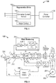
- FIG. 1 illustrates a regenerative drive system 100 in an exemplary embodiment.
- the regenerative drive system 100 may be included as a part of an elevator or elevator system.
- the regenerative drive system 100 may be used to capture energy that would otherwise be expended in operating the elevator, thereby improving the efficiency of the elevator.
- the regenerative drive system 100 may include a regenerative drive 102.
- the regenerative drive 102 may include a converter current sensor 104.
- the converter current sensor 104 may be used to sense so-called "R", “S”, and “T” currents, as those currents are known to those of skill in the art.
- the sensed currents which may be associated with one or more power supplies, may be provided to a controller (not shown in FIG. 1 ) to regulate operation of a power converter 106.
- the power converter 106 may be configured to control a bus voltage (e.g., a DC bus voltage) and maintain it at a selected level by controlling active power/current flow into the regenerative drive 102 from input lines connected to the "R", "S", and “T” input terminals.
- a bus voltage e.g., a DC bus voltage
- a feeder current via the converter current sensor 104 may be used during, e.g., a peak power condition.
- the feeder current may be compared to a threshold, such as a nominal peak current threshold for a given AC line voltage.
- a threshold such as a nominal peak current threshold for a given AC line voltage.
- the speed of the elevator may be controlled via the profile associated with the feeder current without increasing the motor current, which could be a result of overload in an elevator car or excessive field weakening.
- Output power may be obtained by examining the input to a converter (e.g., converter 106).
- the input power to the converter may correspond to the power associated with an inverter, since the power might have nowhere else to go.
- the regenerative drive 102 may include a motor control 108.
- a more detailed view of the motor control 108 is provided in FIG. 2 .
- the functionality and structure associated with some of the components and devices shown in FIG. 2 are known to those of skill in the art. As such, and for the sake of brevity, a complete description of those components/devices is omitted herein.
- the motor control 108 may include an encoder 202.
- the encoder 202 may be configured to provide a position of a machine or motor 204 as it rotates.
- the encoder 202 may be configured to provide speed of the motor 204. For example, delta positioning techniques, potentially as a function of time, may be used to obtain the speed of the motor 204.
- the motor control 108 may include a field orientation device 206.
- the field orientation device 206 may be configured to rotate or manipulate AC currents into a frame where the currents appear as if they are DC currents. Such manipulation may be used to enhance control and resolution.
- the field orientation device 206 may be configured to generate a speed feedback ( ⁇ r ).
- the speed feedback ⁇ r may be provided to a speed controller or PI regulator 208.
- the PI regulator 208 may receive as an input a speed reference ( ⁇ r *).
- the PI regulator 208 may compare the speed feedback ⁇ r to the speed reference ⁇ r * and may generate an output signal 210 based on the comparison.
- the signal 210 may correspond to a torque reference that may be used by a torque controller 212. Based on the torque reference, the torque controller 212 may attempt to operate the motor 204 at a specified torque to obtain a particular speed. In this way, the speed of the motor 204 may be controlled or regulated.
- the motor 204 may run out of or be starved of voltage.
- a field weakening 214 may be used to inject additional current (which may be included in i d *) to compensate for the sag in the voltage.
- motor current references may be used to calculate total motor current, where a q-axis reference (i q *) may come from the regulator 208 output as described above, and a d-axis reference (i d *) may correspond to a summation of the maximum torque per ampere current (i d **) and the motor voltage regulator output current (e.g., the output of the field weakening 214, which may be referred to as i d fwref).
- the total motor current may be equal to sqrt[(i d *) ⁇ 2 + (i q *) ⁇ 2], where sqrt is the square root function applied to the argument.
- FIG. 3 illustrates a method that may be used in connection with one or more devices or systems, such as those described herein.
- the method of FIG. 3 may be used to regulate a speed of an elevator or motor based on a speed regulator (e.g., the regulator 208) output as described further below.
- a speed regulator e.g., the regulator 208
- a load associated with the elevator may be determined.
- the load may be expressed in accordance with one or more terms, such as a weight.
- the weight may be expressed as a fraction or percentage of a rated weight that the motor is capable of supporting.
- the determined load of block 302 may be compared to a threshold.
- the determined load e.g., weight
- the threshold e.g., the "Yes" path is taken out of block 304
- an overload condition may be declared in block 306.
- the elevator may remain at its current location or floor, and flow may proceed back to block 302 to determine the load in order to check for when the excess load has been removed or eliminated.
- the determined load does not exceed the threshold (e.g., the "No" path is taken out of block 304)
- flow may proceed to block 308.
- elevator motion may be enabled. From there, flow may proceed to block 310.
- an output of the speed regulator may be checked or examined.
- the speed regulator output may be checked in connection with a number of events. For example, the speed regulator output may be checked right after pre-torque, when holding the elevator car. The speed regulator output may be checked during an acceleration phase to determine a running speed of the elevator.
- the speed regulator output may be used as a torque current reference (e.g., i q *) for the current regulators where it is indicative of the torque current. From block 310, flow may proceed to block 312.
- the speed regulator output or torque current reference may be used to infer or calculate the motor current.
- the speed regulator output may be compared to one or more thresholds. For example, a first threshold may be used when holding the car and a second threshold, which may be different from the first threshold, may be used during acceleration.
- a determination may be made whether the motor current is within the capacity or limit of the drive and/or motor. If the motor current is within the capacity/limit (e.g., the "Yes" path is taken out of block 312), flow may proceed to block 314 where the current elevator operation or run may be finished. On the other hand, if the motor current is not within the capacity/limit (e.g., the "No" path is taken out of block 312), flow may proceed to block 316.
- one or more actions may be taken in response to the motor current exceeding the capacity/limit.
- the elevator may be forced to stop or halt.
- the elevator may be gracefully or slowly brought to a stop and may run back to an initial position.
- a speed reference e.g., ⁇ r *
- the elevator may proceed to an initial landing.
- FIG. 4 illustrates a method that may be used in connection with one or more devices or systems, such as those described herein.
- the method of FIG. 4 may be used to regulate a speed of an elevator or motor based on a speed regulator (e.g., the regulator 208) output, potentially in combination with an encoder (e.g., encoder 202) output and a bus voltage, as described further below.
- a speed regulator e.g., the regulator 208
- an encoder e.g., encoder 202
- the speed regulator output may be obtained.
- the speed regulator output may correspond to i q * and may be obtained in a manner similar to block 310 described above.
- the encoder speed calculation ( ⁇ encoder ) may be obtained.
- Kt a motor torque value
- motor power may be calculated based on blocks 402-406.
- V bus may be measured.
- V bus may correspond to a drive DC bus voltage, which could be a battery voltage in a battery-based drive.
- an efficiency parameter ( ⁇ ) and a power factor parameter (PF) for the motor may be obtained.
- ⁇ and PF may be (approximately) constant for a given motor.
- ⁇ and PF, and potentially Kt may be stored in a memory or table, potentially in connection with one or more software programs when the motor or elevator is installed.
- the motor current (I motor ) may be calculated based on blocks 402-412.
- motor voltage may be used to determine a speed (e.g., a maximum speed) for an elevator run or operation.
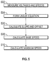
- FIG. 5 illustrates a method for determining a maximum speed for a run based on a motor voltage. The method of FIG. 5 may be used in connection with one or more devices or systems, such as those described herein.
- voltage measurements or readings may be conducted. For example, during a constant acceleration two voltage readings (V 1 and V 2 ) may be taken at two different speeds (w 1 and w 2 ). The voltage readings may be commanded or sensed.
- a linear equation may be formed between the voltage (V) and the speed (w).
- the base speed (w base ) may be indicative of the speed at which the elevator begins to "jerk" into constant velocity.
- the maximum speed (w max ) may correspond to a maximum constant speed an elevator can achieve for a given load condition provided that the floor to floor distance and acceleration and jerk rates allow this maximum speed to be achieved.
- motor voltage may be maintained at the maximum level at full speed using a motor voltage regulator.
- FIGS. 3-5 are illustrative. In some embodiments, one or more of the blocks or operations (or portions thereof) may be optional. In some embodiments, the operations may execute in an order or sequence different from what is shown. In some embodiments, additional operations not shown may be included.
- Embodiments of the disclosure may maximize elevator performance. For example, such maximization may be determined in accordance with one or more of an acceleration, velocity, or speed. Embodiments of the disclosure may serve to minimize current or power consumption by an elevator.
- an elevator speed governor may regulate the operation of an elevator.
- the governor may be configured to deal with or handle power and propulsion limitations associated with the elevator or the elevator's motor.
- Embodiments of the disclosure may determine a load associated with an elevator and select a speed for the elevator based on the load.
- a current e.g., a total current
- operation of an elevator may be based on one or more of a current command (produced by a velocity control unit), a drive input current, and a motor voltage.
- various functions or acts may take place at a given location and/or in connection with the operation of one or more apparatuses, systems, or devices. For example, in some embodiments, a portion of a given function or act may be performed at a first device or location, and the remainder of the function or act may be performed at one or more additional devices or locations.
- an apparatus or system may include one or more processors, and memory storing instructions that, when executed by the one or more processors, cause the apparatus or system to perform one or more methodological acts as described herein.
- one or more input/output (I/O) interfaces may be coupled to one or more processors and may be used to provide a user with an interface to an elevator system.
- I/O input/output
- Various mechanical components known to those of skill in the art may be used in some embodiments.
- Embodiments may be implemented as one or more apparatuses, systems, and/or methods.
- instructions may be stored on one or more computer-readable media, such as a transitory and/or non-transitory computer-readable medium.
- the instructions when executed, may cause an entity (e.g., an apparatus or system) to perform one or more methodological acts as described herein.
- Embodiments may be tied to one or more particular machines.
- one or more architectures or controllers may be configured to control or regulate the speed of an elevator.
- the speed of the elevator may be based on a motor current that may be calculated or computed without the use of a current sensor.
- the motor current may be determined based on one or more of a speed regulator output, a motor torque value, an encoder speed, a bus voltage, and a summation of motor current references.
- a drive or converter input current or a motor voltage may be used to determine or regulate motor current and/or elevator speed.
Landscapes
- Engineering & Computer Science (AREA)
- Automation & Control Theory (AREA)
- Elevator Control (AREA)
- Control Of Ac Motors In General (AREA)
- Control Of Linear Motors (AREA)
Priority Applications (1)
| Application Number | Priority Date | Filing Date | Title |
|---|---|---|---|
| EP21153283.3A EP3845478B1 (de) | 2012-12-13 | 2012-12-13 | Aufzuggeschwindigkeitsüberwachung |
Applications Claiming Priority (3)
| Application Number | Priority Date | Filing Date | Title |
|---|---|---|---|
| EP21153283.3A EP3845478B1 (de) | 2012-12-13 | 2012-12-13 | Aufzuggeschwindigkeitsüberwachung |
| PCT/US2012/069425 WO2014092707A1 (en) | 2012-12-13 | 2012-12-13 | Elevator speed control |
| EP12889747.7A EP2931639B1 (de) | 2012-12-13 | 2012-12-13 | Aufzuggeschwindigkeitsüberwachung |
Related Parent Applications (1)
| Application Number | Title | Priority Date | Filing Date |
|---|---|---|---|
| EP12889747.7A Division EP2931639B1 (de) | 2012-12-13 | 2012-12-13 | Aufzuggeschwindigkeitsüberwachung |
Publications (3)
| Publication Number | Publication Date |
|---|---|
| EP3845478A2 true EP3845478A2 (de) | 2021-07-07 |
| EP3845478A3 EP3845478A3 (de) | 2021-10-27 |
| EP3845478B1 EP3845478B1 (de) | 2024-05-01 |
Family
ID=50934779
Family Applications (2)
| Application Number | Title | Priority Date | Filing Date |
|---|---|---|---|
| EP12889747.7A Active EP2931639B1 (de) | 2012-12-13 | 2012-12-13 | Aufzuggeschwindigkeitsüberwachung |
| EP21153283.3A Active EP3845478B1 (de) | 2012-12-13 | 2012-12-13 | Aufzuggeschwindigkeitsüberwachung |
Family Applications Before (1)
| Application Number | Title | Priority Date | Filing Date |
|---|---|---|---|
| EP12889747.7A Active EP2931639B1 (de) | 2012-12-13 | 2012-12-13 | Aufzuggeschwindigkeitsüberwachung |
Country Status (4)
| Country | Link |
|---|---|
| US (1) | US9957131B2 (de) |
| EP (2) | EP2931639B1 (de) |
| CN (1) | CN104854009B (de) |
| WO (1) | WO2014092707A1 (de) |
Families Citing this family (8)
| Publication number | Priority date | Publication date | Assignee | Title |
|---|---|---|---|---|
| EP2931639B1 (de) * | 2012-12-13 | 2021-01-27 | Otis Elevator Company | Aufzuggeschwindigkeitsüberwachung |
| CN105980284B (zh) * | 2014-02-06 | 2019-10-22 | 奥的斯电梯公司 | 电梯中的制动器操作管理 |
| JP6309847B2 (ja) * | 2014-07-14 | 2018-04-11 | ファナック株式会社 | 定格ワークパラメータを超えるワークを搬送可能なロボット制御装置 |
| US10211763B2 (en) | 2016-02-29 | 2019-02-19 | Linestream Technologies | Method for automatically identifying speed operation range in a mechanical system driven by PMSM or induction motors under friction and load condition |
| US10184917B2 (en) | 2016-09-08 | 2019-01-22 | Linestream Technologies | Method for automatically identifying resonance |
| US10604378B2 (en) * | 2017-06-14 | 2020-03-31 | Otis Elevator Company | Emergency elevator power management |
| JP7157772B2 (ja) * | 2020-01-10 | 2022-10-20 | 株式会社日立製作所 | エレベーター制御装置及びエレベーター制御方法 |
| CN116639565A (zh) * | 2023-05-25 | 2023-08-25 | 上海三菱电梯有限公司 | 可变速电梯异常分级保护系统 |
Family Cites Families (22)
| Publication number | Priority date | Publication date | Assignee | Title |
|---|---|---|---|---|
| NL7009672A (de) * | 1969-06-30 | 1971-01-04 | ||
| JPS51131045A (en) * | 1975-05-07 | 1976-11-15 | Hitachi Ltd | Elevator speed pattern producing device |
| JPS51131044A (en) * | 1975-05-09 | 1976-11-15 | Hitachi Ltd | Ac elevator controlling device |
| FI79209C (fi) * | 1986-03-19 | 1989-11-10 | Kone Oy | Anordning foer styrning av en trefasig inverter som matar vaexelstroemmotorn vid en hiss. |
| JPS63220947A (ja) * | 1987-03-06 | 1988-09-14 | Sintokogio Ltd | 生砂中子の造型方法及びその装置 |
| US5325036A (en) * | 1992-06-15 | 1994-06-28 | Otis Elevator Company | Elevator speed sensorless variable voltage variable frequency induction motor drive |
| JPH11299290A (ja) * | 1998-04-17 | 1999-10-29 | Hitachi Ltd | 交流電動機駆動システム |
| MXPA04007458A (es) * | 2002-01-31 | 2005-07-13 | Inventio Ag | Elevador, particularmente para transportar pasajeros. |
| EP1460022A1 (de) * | 2003-03-20 | 2004-09-22 | Inventio Ag | Antriebseinheit für einen aufzug |
| JP4098182B2 (ja) * | 2003-08-07 | 2008-06-11 | 株式会社日立製作所 | モータ駆動システム及びエレベータ駆動システム |
| US7268514B2 (en) * | 2004-11-30 | 2007-09-11 | Rockwell Automation Technologies, Inc. | Motor control for stopping a load and detecting mechanical brake slippage |
| JP5036147B2 (ja) * | 2005-07-11 | 2012-09-26 | 東芝エレベータ株式会社 | エレベータの速度制御装置、速度制御方法、および速度制御プログラム |
| US7327111B2 (en) * | 2005-08-12 | 2008-02-05 | Siemens Energy & Automation, Inc. | System and method for parallel control of variable frequency drives |
| FI119792B (fi) * | 2007-01-24 | 2009-03-13 | Kone Corp | Menetelmä ja laitteisto moottorin ohjaamiseksi |
| ES2689089T3 (es) | 2007-02-13 | 2018-11-08 | Otis Elevator Company | Operación automática de rescate para un sistema de variador regenerativo |
| FI120193B (fi) * | 2008-01-09 | 2009-07-31 | Kone Corp | Hissijärjestelmän liikkeenohjaus |
| JP2010168139A (ja) * | 2009-01-21 | 2010-08-05 | Hitachi Ltd | エレベーター制御装置 |
| IT1393876B1 (it) * | 2009-04-29 | 2012-05-11 | Brea Impianti S U R L | Sistema di controllo per un impianto elevatore oleodinamico |
| FI122183B (fi) * | 2010-03-15 | 2011-09-30 | Kone Corp | Menetelmä ja laite hissin sähkökäytön käyntiinajamiseksi |
| FI122125B (fi) * | 2010-04-07 | 2011-08-31 | Kone Corp | Säätölaite ja hissin sähkökäyttö |
| FI122598B (fi) * | 2011-04-01 | 2012-04-13 | Kone Corp | Menetelmä hissijärjestelmän toimintakunnon valvomiseksi |
| EP2931639B1 (de) * | 2012-12-13 | 2021-01-27 | Otis Elevator Company | Aufzuggeschwindigkeitsüberwachung |
-
2012
- 2012-12-13 EP EP12889747.7A patent/EP2931639B1/de active Active
- 2012-12-13 WO PCT/US2012/069425 patent/WO2014092707A1/en not_active Ceased
- 2012-12-13 US US14/651,284 patent/US9957131B2/en active Active
- 2012-12-13 CN CN201280077664.7A patent/CN104854009B/zh active Active
- 2012-12-13 EP EP21153283.3A patent/EP3845478B1/de active Active
Also Published As
| Publication number | Publication date |
|---|---|
| US20150329317A1 (en) | 2015-11-19 |
| EP3845478A3 (de) | 2021-10-27 |
| US9957131B2 (en) | 2018-05-01 |
| EP2931639A1 (de) | 2015-10-21 |
| EP3845478B1 (de) | 2024-05-01 |
| EP2931639A4 (de) | 2016-08-10 |
| WO2014092707A1 (en) | 2014-06-19 |
| CN104854009A (zh) | 2015-08-19 |
| CN104854009B (zh) | 2020-06-16 |
| EP2931639B1 (de) | 2021-01-27 |
Similar Documents
| Publication | Publication Date | Title |
|---|---|---|
| EP2931639B1 (de) | Aufzuggeschwindigkeitsüberwachung | |
| KR101236621B1 (ko) | 인버터 제어장치 | |
| JP4343381B2 (ja) | エレベーターの制御装置 | |
| US8348020B2 (en) | Elevator control device with carrier frequency switch circuit | |
| JP2009142115A (ja) | モータ制御装置とその故障検出方法 | |
| ES2900245T3 (es) | Inversor | |
| EP2597062B1 (de) | Aufzugssteuerungsverfahren, Aufzugssteuerungsvorrichtung und Aufzugsvorrichtung damit | |
| JP7142719B2 (ja) | モータ制御装置 | |
| CN107074114A (zh) | 用于引航电动摩托车等中的电动马达的系统 | |
| US10882407B2 (en) | Low engine speed electric accessory load regulation on moving vehicles | |
| EP3358729B1 (de) | Vorrichtung zur steuerung eines motors | |
| EP2336068A1 (de) | Energieverwaltungsverfahren und -system für einen elektrischen Motor | |
| CN100398426C (zh) | 电梯控制装置 | |
| JP7732582B2 (ja) | エレベータードアの制御装置 | |
| JP2008306901A (ja) | インバータ装置 | |
| JP5726929B2 (ja) | 建設機械及び建設機械の制御方法 | |
| US20140035507A1 (en) | Motor deceleration method and motor driving apparatus applying the motor deceleration method | |
| CN108736790B (zh) | 伺服电动机的控制装置及方法 | |
| KR102534296B1 (ko) | 전동기 제어 방법 및 이를 이용하는 전동기 제어 장치 | |
| JP3832325B2 (ja) | エレベータの制御装置 | |
| JP6156019B2 (ja) | 倒立型移動体の制御方法 | |
| JP2009294102A (ja) | 蓄電器の内部抵抗の測定方法及び内部抵抗測定装置 | |
| WO2013105248A1 (ja) | 電気車制御装置 | |
| JP2009294188A (ja) | 充電電圧の測定方法及び充電電圧測定装置 | |
| CN108934185B (zh) | 逆变器装置及电动机的轻负荷判定方法 |
Legal Events
| Date | Code | Title | Description |
|---|---|---|---|
| PUAI | Public reference made under article 153(3) epc to a published international application that has entered the european phase |
Free format text: ORIGINAL CODE: 0009012 |
|
| STAA | Information on the status of an ep patent application or granted ep patent |
Free format text: STATUS: THE APPLICATION HAS BEEN PUBLISHED |
|
| AC | Divisional application: reference to earlier application |
Ref document number: 2931639 Country of ref document: EP Kind code of ref document: P |
|
| AK | Designated contracting states |
Kind code of ref document: A2 Designated state(s): AL AT BE BG CH CY CZ DE DK EE ES FI FR GB GR HR HU IE IS IT LI LT LU LV MC MK MT NL NO PL PT RO RS SE SI SK SM TR |
|
| PUAL | Search report despatched |
Free format text: ORIGINAL CODE: 0009013 |
|
| AK | Designated contracting states |
Kind code of ref document: A3 Designated state(s): AL AT BE BG CH CY CZ DE DK EE ES FI FR GB GR HR HU IE IS IT LI LT LU LV MC MK MT NL NO PL PT RO RS SE SI SK SM TR |
|
| RIC1 | Information provided on ipc code assigned before grant |
Ipc: B66B 1/30 20060101AFI20210921BHEP |
|
| STAA | Information on the status of an ep patent application or granted ep patent |
Free format text: STATUS: REQUEST FOR EXAMINATION WAS MADE |
|
| 17P | Request for examination filed |
Effective date: 20220425 |
|
| RBV | Designated contracting states (corrected) |
Designated state(s): AL AT BE BG CH CY CZ DE DK EE ES FI FR GB GR HR HU IE IS IT LI LT LU LV MC MK MT NL NO PL PT RO RS SE SI SK SM TR |
|
| GRAP | Despatch of communication of intention to grant a patent |
Free format text: ORIGINAL CODE: EPIDOSNIGR1 |
|
| STAA | Information on the status of an ep patent application or granted ep patent |
Free format text: STATUS: GRANT OF PATENT IS INTENDED |
|
| INTG | Intention to grant announced |
Effective date: 20231218 |
|
| GRAS | Grant fee paid |
Free format text: ORIGINAL CODE: EPIDOSNIGR3 |
|
| GRAA | (expected) grant |
Free format text: ORIGINAL CODE: 0009210 |
|
| STAA | Information on the status of an ep patent application or granted ep patent |
Free format text: STATUS: THE PATENT HAS BEEN GRANTED |
|
| AC | Divisional application: reference to earlier application |
Ref document number: 2931639 Country of ref document: EP Kind code of ref document: P |
|
| AK | Designated contracting states |
Kind code of ref document: B1 Designated state(s): AL AT BE BG CH CY CZ DE DK EE ES FI FR GB GR HR HU IE IS IT LI LT LU LV MC MK MT NL NO PL PT RO RS SE SI SK SM TR |
|
| REG | Reference to a national code |
Ref country code: GB Ref legal event code: FG4D |
|
| REG | Reference to a national code |
Ref country code: CH Ref legal event code: EP |
|
| REG | Reference to a national code |
Ref country code: IE Ref legal event code: FG4D |
|
| REG | Reference to a national code |
Ref country code: DE Ref legal event code: R096 Ref document number: 602012080769 Country of ref document: DE |
|
| REG | Reference to a national code |
Ref country code: LT Ref legal event code: MG9D |
|
| REG | Reference to a national code |
Ref country code: NL Ref legal event code: MP Effective date: 20240501 |
|
| PG25 | Lapsed in a contracting state [announced via postgrant information from national office to epo] |
Ref country code: IS Free format text: LAPSE BECAUSE OF FAILURE TO SUBMIT A TRANSLATION OF THE DESCRIPTION OR TO PAY THE FEE WITHIN THE PRESCRIBED TIME-LIMIT Effective date: 20240901 |
|
| PG25 | Lapsed in a contracting state [announced via postgrant information from national office to epo] |
Ref country code: BG Free format text: LAPSE BECAUSE OF FAILURE TO SUBMIT A TRANSLATION OF THE DESCRIPTION OR TO PAY THE FEE WITHIN THE PRESCRIBED TIME-LIMIT Effective date: 20240501 |
|
| PG25 | Lapsed in a contracting state [announced via postgrant information from national office to epo] |
Ref country code: FI Free format text: LAPSE BECAUSE OF FAILURE TO SUBMIT A TRANSLATION OF THE DESCRIPTION OR TO PAY THE FEE WITHIN THE PRESCRIBED TIME-LIMIT Effective date: 20240501 Ref country code: HR Free format text: LAPSE BECAUSE OF FAILURE TO SUBMIT A TRANSLATION OF THE DESCRIPTION OR TO PAY THE FEE WITHIN THE PRESCRIBED TIME-LIMIT Effective date: 20240501 |
|
| PG25 | Lapsed in a contracting state [announced via postgrant information from national office to epo] |
Ref country code: GR Free format text: LAPSE BECAUSE OF FAILURE TO SUBMIT A TRANSLATION OF THE DESCRIPTION OR TO PAY THE FEE WITHIN THE PRESCRIBED TIME-LIMIT Effective date: 20240802 |
|
| PG25 | Lapsed in a contracting state [announced via postgrant information from national office to epo] |
Ref country code: PT Free format text: LAPSE BECAUSE OF FAILURE TO SUBMIT A TRANSLATION OF THE DESCRIPTION OR TO PAY THE FEE WITHIN THE PRESCRIBED TIME-LIMIT Effective date: 20240902 |
|
| REG | Reference to a national code |
Ref country code: AT Ref legal event code: MK05 Ref document number: 1682119 Country of ref document: AT Kind code of ref document: T Effective date: 20240501 |
|
| PG25 | Lapsed in a contracting state [announced via postgrant information from national office to epo] |
Ref country code: NL Free format text: LAPSE BECAUSE OF FAILURE TO SUBMIT A TRANSLATION OF THE DESCRIPTION OR TO PAY THE FEE WITHIN THE PRESCRIBED TIME-LIMIT Effective date: 20240501 |
|
| PG25 | Lapsed in a contracting state [announced via postgrant information from national office to epo] |
Ref country code: ES Free format text: LAPSE BECAUSE OF FAILURE TO SUBMIT A TRANSLATION OF THE DESCRIPTION OR TO PAY THE FEE WITHIN THE PRESCRIBED TIME-LIMIT Effective date: 20240501 |
|
| PG25 | Lapsed in a contracting state [announced via postgrant information from national office to epo] |
Ref country code: AT Free format text: LAPSE BECAUSE OF FAILURE TO SUBMIT A TRANSLATION OF THE DESCRIPTION OR TO PAY THE FEE WITHIN THE PRESCRIBED TIME-LIMIT Effective date: 20240501 |
|
| PG25 | Lapsed in a contracting state [announced via postgrant information from national office to epo] |
Ref country code: PL Free format text: LAPSE BECAUSE OF FAILURE TO SUBMIT A TRANSLATION OF THE DESCRIPTION OR TO PAY THE FEE WITHIN THE PRESCRIBED TIME-LIMIT Effective date: 20240501 |
|
| PG25 | Lapsed in a contracting state [announced via postgrant information from national office to epo] |
Ref country code: LV Free format text: LAPSE BECAUSE OF FAILURE TO SUBMIT A TRANSLATION OF THE DESCRIPTION OR TO PAY THE FEE WITHIN THE PRESCRIBED TIME-LIMIT Effective date: 20240501 |
|
| PG25 | Lapsed in a contracting state [announced via postgrant information from national office to epo] |
Ref country code: PT Free format text: LAPSE BECAUSE OF FAILURE TO SUBMIT A TRANSLATION OF THE DESCRIPTION OR TO PAY THE FEE WITHIN THE PRESCRIBED TIME-LIMIT Effective date: 20240902 Ref country code: PL Free format text: LAPSE BECAUSE OF FAILURE TO SUBMIT A TRANSLATION OF THE DESCRIPTION OR TO PAY THE FEE WITHIN THE PRESCRIBED TIME-LIMIT Effective date: 20240501 Ref country code: NO Free format text: LAPSE BECAUSE OF FAILURE TO SUBMIT A TRANSLATION OF THE DESCRIPTION OR TO PAY THE FEE WITHIN THE PRESCRIBED TIME-LIMIT Effective date: 20240801 Ref country code: NL Free format text: LAPSE BECAUSE OF FAILURE TO SUBMIT A TRANSLATION OF THE DESCRIPTION OR TO PAY THE FEE WITHIN THE PRESCRIBED TIME-LIMIT Effective date: 20240501 Ref country code: LV Free format text: LAPSE BECAUSE OF FAILURE TO SUBMIT A TRANSLATION OF THE DESCRIPTION OR TO PAY THE FEE WITHIN THE PRESCRIBED TIME-LIMIT Effective date: 20240501 Ref country code: IS Free format text: LAPSE BECAUSE OF FAILURE TO SUBMIT A TRANSLATION OF THE DESCRIPTION OR TO PAY THE FEE WITHIN THE PRESCRIBED TIME-LIMIT Effective date: 20240901 Ref country code: HR Free format text: LAPSE BECAUSE OF FAILURE TO SUBMIT A TRANSLATION OF THE DESCRIPTION OR TO PAY THE FEE WITHIN THE PRESCRIBED TIME-LIMIT Effective date: 20240501 Ref country code: GR Free format text: LAPSE BECAUSE OF FAILURE TO SUBMIT A TRANSLATION OF THE DESCRIPTION OR TO PAY THE FEE WITHIN THE PRESCRIBED TIME-LIMIT Effective date: 20240802 Ref country code: FI Free format text: LAPSE BECAUSE OF FAILURE TO SUBMIT A TRANSLATION OF THE DESCRIPTION OR TO PAY THE FEE WITHIN THE PRESCRIBED TIME-LIMIT Effective date: 20240501 Ref country code: ES Free format text: LAPSE BECAUSE OF FAILURE TO SUBMIT A TRANSLATION OF THE DESCRIPTION OR TO PAY THE FEE WITHIN THE PRESCRIBED TIME-LIMIT Effective date: 20240501 Ref country code: BG Free format text: LAPSE BECAUSE OF FAILURE TO SUBMIT A TRANSLATION OF THE DESCRIPTION OR TO PAY THE FEE WITHIN THE PRESCRIBED TIME-LIMIT Effective date: 20240501 Ref country code: AT Free format text: LAPSE BECAUSE OF FAILURE TO SUBMIT A TRANSLATION OF THE DESCRIPTION OR TO PAY THE FEE WITHIN THE PRESCRIBED TIME-LIMIT Effective date: 20240501 Ref country code: RS Free format text: LAPSE BECAUSE OF FAILURE TO SUBMIT A TRANSLATION OF THE DESCRIPTION OR TO PAY THE FEE WITHIN THE PRESCRIBED TIME-LIMIT Effective date: 20240801 |
|
| PG25 | Lapsed in a contracting state [announced via postgrant information from national office to epo] |
Ref country code: DK Free format text: LAPSE BECAUSE OF FAILURE TO SUBMIT A TRANSLATION OF THE DESCRIPTION OR TO PAY THE FEE WITHIN THE PRESCRIBED TIME-LIMIT Effective date: 20240501 |
|
| PG25 | Lapsed in a contracting state [announced via postgrant information from national office to epo] |
Ref country code: EE Free format text: LAPSE BECAUSE OF FAILURE TO SUBMIT A TRANSLATION OF THE DESCRIPTION OR TO PAY THE FEE WITHIN THE PRESCRIBED TIME-LIMIT Effective date: 20240501 |
|
| PG25 | Lapsed in a contracting state [announced via postgrant information from national office to epo] |
Ref country code: CZ Free format text: LAPSE BECAUSE OF FAILURE TO SUBMIT A TRANSLATION OF THE DESCRIPTION OR TO PAY THE FEE WITHIN THE PRESCRIBED TIME-LIMIT Effective date: 20240501 |
|
| PG25 | Lapsed in a contracting state [announced via postgrant information from national office to epo] |
Ref country code: SK Free format text: LAPSE BECAUSE OF FAILURE TO SUBMIT A TRANSLATION OF THE DESCRIPTION OR TO PAY THE FEE WITHIN THE PRESCRIBED TIME-LIMIT Effective date: 20240501 Ref country code: RO Free format text: LAPSE BECAUSE OF FAILURE TO SUBMIT A TRANSLATION OF THE DESCRIPTION OR TO PAY THE FEE WITHIN THE PRESCRIBED TIME-LIMIT Effective date: 20240501 |
|
| PG25 | Lapsed in a contracting state [announced via postgrant information from national office to epo] |
Ref country code: SM Free format text: LAPSE BECAUSE OF FAILURE TO SUBMIT A TRANSLATION OF THE DESCRIPTION OR TO PAY THE FEE WITHIN THE PRESCRIBED TIME-LIMIT Effective date: 20240501 |
|
| PG25 | Lapsed in a contracting state [announced via postgrant information from national office to epo] |
Ref country code: SM Free format text: LAPSE BECAUSE OF FAILURE TO SUBMIT A TRANSLATION OF THE DESCRIPTION OR TO PAY THE FEE WITHIN THE PRESCRIBED TIME-LIMIT Effective date: 20240501 Ref country code: SK Free format text: LAPSE BECAUSE OF FAILURE TO SUBMIT A TRANSLATION OF THE DESCRIPTION OR TO PAY THE FEE WITHIN THE PRESCRIBED TIME-LIMIT Effective date: 20240501 Ref country code: RO Free format text: LAPSE BECAUSE OF FAILURE TO SUBMIT A TRANSLATION OF THE DESCRIPTION OR TO PAY THE FEE WITHIN THE PRESCRIBED TIME-LIMIT Effective date: 20240501 Ref country code: EE Free format text: LAPSE BECAUSE OF FAILURE TO SUBMIT A TRANSLATION OF THE DESCRIPTION OR TO PAY THE FEE WITHIN THE PRESCRIBED TIME-LIMIT Effective date: 20240501 Ref country code: DK Free format text: LAPSE BECAUSE OF FAILURE TO SUBMIT A TRANSLATION OF THE DESCRIPTION OR TO PAY THE FEE WITHIN THE PRESCRIBED TIME-LIMIT Effective date: 20240501 Ref country code: CZ Free format text: LAPSE BECAUSE OF FAILURE TO SUBMIT A TRANSLATION OF THE DESCRIPTION OR TO PAY THE FEE WITHIN THE PRESCRIBED TIME-LIMIT Effective date: 20240501 |
|
| REG | Reference to a national code |
Ref country code: DE Ref legal event code: R097 Ref document number: 602012080769 Country of ref document: DE |
|
| PG25 | Lapsed in a contracting state [announced via postgrant information from national office to epo] |
Ref country code: IT Free format text: LAPSE BECAUSE OF FAILURE TO SUBMIT A TRANSLATION OF THE DESCRIPTION OR TO PAY THE FEE WITHIN THE PRESCRIBED TIME-LIMIT Effective date: 20240501 |
|
| PLBE | No opposition filed within time limit |
Free format text: ORIGINAL CODE: 0009261 |
|
| STAA | Information on the status of an ep patent application or granted ep patent |
Free format text: STATUS: NO OPPOSITION FILED WITHIN TIME LIMIT |
|
| 26N | No opposition filed |
Effective date: 20250204 |
|
| PG25 | Lapsed in a contracting state [announced via postgrant information from national office to epo] |
Ref country code: SI Free format text: LAPSE BECAUSE OF FAILURE TO SUBMIT A TRANSLATION OF THE DESCRIPTION OR TO PAY THE FEE WITHIN THE PRESCRIBED TIME-LIMIT Effective date: 20240501 |
|
| PG25 | Lapsed in a contracting state [announced via postgrant information from national office to epo] |
Ref country code: MC Free format text: LAPSE BECAUSE OF FAILURE TO SUBMIT A TRANSLATION OF THE DESCRIPTION OR TO PAY THE FEE WITHIN THE PRESCRIBED TIME-LIMIT Effective date: 20240501 |
|
| REG | Reference to a national code |
Ref country code: CH Ref legal event code: PL |
|
| PG25 | Lapsed in a contracting state [announced via postgrant information from national office to epo] |
Ref country code: LU Free format text: LAPSE BECAUSE OF NON-PAYMENT OF DUE FEES Effective date: 20241213 |
|
| PG25 | Lapsed in a contracting state [announced via postgrant information from national office to epo] |
Ref country code: SE Free format text: LAPSE BECAUSE OF FAILURE TO SUBMIT A TRANSLATION OF THE DESCRIPTION OR TO PAY THE FEE WITHIN THE PRESCRIBED TIME-LIMIT Effective date: 20240501 |
|
| REG | Reference to a national code |
Ref country code: BE Ref legal event code: MM Effective date: 20241231 |
|
| PG25 | Lapsed in a contracting state [announced via postgrant information from national office to epo] |
Ref country code: BE Free format text: LAPSE BECAUSE OF NON-PAYMENT OF DUE FEES Effective date: 20241231 |
|
| PG25 | Lapsed in a contracting state [announced via postgrant information from national office to epo] |
Ref country code: CH Free format text: LAPSE BECAUSE OF NON-PAYMENT OF DUE FEES Effective date: 20241231 |
|
| PG25 | Lapsed in a contracting state [announced via postgrant information from national office to epo] |
Ref country code: IE Free format text: LAPSE BECAUSE OF NON-PAYMENT OF DUE FEES Effective date: 20241213 |
|
| PGFP | Annual fee paid to national office [announced via postgrant information from national office to epo] |
Ref country code: DE Payment date: 20251126 Year of fee payment: 14 |
|
| PGFP | Annual fee paid to national office [announced via postgrant information from national office to epo] |
Ref country code: GB Payment date: 20251120 Year of fee payment: 14 |
|
| PGFP | Annual fee paid to national office [announced via postgrant information from national office to epo] |
Ref country code: FR Payment date: 20251120 Year of fee payment: 14 |