EP3845469A1 - Tube container - Google Patents
Tube container Download PDFInfo
- Publication number
- EP3845469A1 EP3845469A1 EP19855198.8A EP19855198A EP3845469A1 EP 3845469 A1 EP3845469 A1 EP 3845469A1 EP 19855198 A EP19855198 A EP 19855198A EP 3845469 A1 EP3845469 A1 EP 3845469A1
- Authority
- EP
- European Patent Office
- Prior art keywords
- layer
- polyethylene
- resin layer
- reinforcing tape
- thickness
- Prior art date
- Legal status (The legal status is an assumption and is not a legal conclusion. Google has not performed a legal analysis and makes no representation as to the accuracy of the status listed.)
- Pending
Links
- 239000010410 layer Substances 0.000 claims abstract description 217
- 230000003014 reinforcing effect Effects 0.000 claims abstract description 97
- 229920005678 polyethylene based resin Polymers 0.000 claims abstract description 57
- 239000011241 protective layer Substances 0.000 claims abstract description 52
- 239000011888 foil Substances 0.000 claims description 37
- -1 polyethylene terephthalate Polymers 0.000 claims description 30
- 230000004888 barrier function Effects 0.000 claims description 22
- 239000000463 material Substances 0.000 claims description 21
- 229920000139 polyethylene terephthalate Polymers 0.000 claims description 20
- 239000005020 polyethylene terephthalate Substances 0.000 claims description 20
- 229910052751 metal Inorganic materials 0.000 claims description 12
- 239000002184 metal Substances 0.000 claims description 12
- 239000000470 constituent Substances 0.000 claims description 4
- 229920005989 resin Polymers 0.000 abstract description 42
- 239000011347 resin Substances 0.000 abstract description 42
- 229910052782 aluminium Inorganic materials 0.000 description 49
- XAGFODPZIPBFFR-UHFFFAOYSA-N aluminium Chemical compound [Al] XAGFODPZIPBFFR-UHFFFAOYSA-N 0.000 description 49
- 239000004698 Polyethylene Substances 0.000 description 25
- 229920000573 polyethylene Polymers 0.000 description 25
- 239000012790 adhesive layer Substances 0.000 description 24
- 238000005304 joining Methods 0.000 description 16
- 229920002799 BoPET Polymers 0.000 description 13
- 229920005672 polyolefin resin Polymers 0.000 description 13
- 239000000203 mixture Substances 0.000 description 12
- 238000007646 gravure printing Methods 0.000 description 10
- 239000004700 high-density polyethylene Substances 0.000 description 10
- 229920001684 low density polyethylene Polymers 0.000 description 10
- 239000004702 low-density polyethylene Substances 0.000 description 10
- 229920001903 high density polyethylene Polymers 0.000 description 9
- 238000007789 sealing Methods 0.000 description 8
- 238000012360 testing method Methods 0.000 description 8
- XLYOFNOQVPJJNP-UHFFFAOYSA-N water Chemical compound O XLYOFNOQVPJJNP-UHFFFAOYSA-N 0.000 description 7
- 238000003466 welding Methods 0.000 description 7
- QVGXLLKOCUKJST-UHFFFAOYSA-N atomic oxygen Chemical compound [O] QVGXLLKOCUKJST-UHFFFAOYSA-N 0.000 description 6
- 238000005034 decoration Methods 0.000 description 6
- 239000001301 oxygen Substances 0.000 description 6
- 229910052760 oxygen Inorganic materials 0.000 description 6
- 229920010126 Linear Low Density Polyethylene (LLDPE) Polymers 0.000 description 5
- 230000000052 comparative effect Effects 0.000 description 5
- 229920000092 linear low density polyethylene Polymers 0.000 description 5
- 239000004707 linear low-density polyethylene Substances 0.000 description 5
- 230000003746 surface roughness Effects 0.000 description 5
- 239000000853 adhesive Substances 0.000 description 4
- 230000007547 defect Effects 0.000 description 4
- 238000002844 melting Methods 0.000 description 4
- 230000008018 melting Effects 0.000 description 4
- BASFCYQUMIYNBI-UHFFFAOYSA-N platinum Chemical compound [Pt] BASFCYQUMIYNBI-UHFFFAOYSA-N 0.000 description 4
- BQCADISMDOOEFD-UHFFFAOYSA-N Silver Chemical compound [Ag] BQCADISMDOOEFD-UHFFFAOYSA-N 0.000 description 3
- 230000006866 deterioration Effects 0.000 description 3
- PCHJSUWPFVWCPO-UHFFFAOYSA-N gold Chemical compound [Au] PCHJSUWPFVWCPO-UHFFFAOYSA-N 0.000 description 3
- 238000000034 method Methods 0.000 description 3
- 230000002787 reinforcement Effects 0.000 description 3
- RYGMFSIKBFXOCR-UHFFFAOYSA-N Copper Chemical compound [Cu] RYGMFSIKBFXOCR-UHFFFAOYSA-N 0.000 description 2
- PXHVJJICTQNCMI-UHFFFAOYSA-N Nickel Chemical compound [Ni] PXHVJJICTQNCMI-UHFFFAOYSA-N 0.000 description 2
- ATJFFYVFTNAWJD-UHFFFAOYSA-N Tin Chemical compound [Sn] ATJFFYVFTNAWJD-UHFFFAOYSA-N 0.000 description 2
- RTAQQCXQSZGOHL-UHFFFAOYSA-N Titanium Chemical compound [Ti] RTAQQCXQSZGOHL-UHFFFAOYSA-N 0.000 description 2
- 230000001070 adhesive effect Effects 0.000 description 2
- 230000015572 biosynthetic process Effects 0.000 description 2
- 230000015556 catabolic process Effects 0.000 description 2
- 230000008859 change Effects 0.000 description 2
- 239000011889 copper foil Substances 0.000 description 2
- 238000006731 degradation reaction Methods 0.000 description 2
- 238000002845 discoloration Methods 0.000 description 2
- 239000007789 gas Substances 0.000 description 2
- 238000007542 hardness measurement Methods 0.000 description 2
- 230000001965 increasing effect Effects 0.000 description 2
- 238000004519 manufacturing process Methods 0.000 description 2
- 238000005259 measurement Methods 0.000 description 2
- 238000012986 modification Methods 0.000 description 2
- 230000004048 modification Effects 0.000 description 2
- 239000004743 Polypropylene Substances 0.000 description 1
- HCHKCACWOHOZIP-UHFFFAOYSA-N Zinc Chemical compound [Zn] HCHKCACWOHOZIP-UHFFFAOYSA-N 0.000 description 1
- 238000000748 compression moulding Methods 0.000 description 1
- 239000002537 cosmetic Substances 0.000 description 1
- 230000000694 effects Effects 0.000 description 1
- 230000002708 enhancing effect Effects 0.000 description 1
- 238000011156 evaluation Methods 0.000 description 1
- 235000011194 food seasoning agent Nutrition 0.000 description 1
- 229910052737 gold Inorganic materials 0.000 description 1
- 239000010931 gold Substances 0.000 description 1
- 230000006872 improvement Effects 0.000 description 1
- 238000003475 lamination Methods 0.000 description 1
- 229920004889 linear high-density polyethylene Polymers 0.000 description 1
- 238000000465 moulding Methods 0.000 description 1
- 229910052759 nickel Inorganic materials 0.000 description 1
- 239000003960 organic solvent Substances 0.000 description 1
- 239000008177 pharmaceutical agent Substances 0.000 description 1
- 229910052697 platinum Inorganic materials 0.000 description 1
- 229920013716 polyethylene resin Polymers 0.000 description 1
- 229920001155 polypropylene Polymers 0.000 description 1
- 238000007639 printing Methods 0.000 description 1
- 239000000047 product Substances 0.000 description 1
- 238000005096 rolling process Methods 0.000 description 1
- 229910052709 silver Inorganic materials 0.000 description 1
- 239000004332 silver Substances 0.000 description 1
- 239000000606 toothpaste Substances 0.000 description 1
- 229940034610 toothpaste Drugs 0.000 description 1
- 229910052725 zinc Inorganic materials 0.000 description 1
- 239000011701 zinc Substances 0.000 description 1
Images



Classifications
-
- B—PERFORMING OPERATIONS; TRANSPORTING
- B65—CONVEYING; PACKING; STORING; HANDLING THIN OR FILAMENTARY MATERIAL
- B65D—CONTAINERS FOR STORAGE OR TRANSPORT OF ARTICLES OR MATERIALS, e.g. BAGS, BARRELS, BOTTLES, BOXES, CANS, CARTONS, CRATES, DRUMS, JARS, TANKS, HOPPERS, FORWARDING CONTAINERS; ACCESSORIES, CLOSURES, OR FITTINGS THEREFOR; PACKAGING ELEMENTS; PACKAGES
- B65D35/00—Pliable tubular containers adapted to be permanently or temporarily deformed to expel contents, e.g. collapsible tubes for toothpaste or other plastic or semi-liquid material; Holders therefor
- B65D35/02—Body construction
- B65D35/10—Body construction made by uniting or interconnecting two or more components
-
- B—PERFORMING OPERATIONS; TRANSPORTING
- B65—CONVEYING; PACKING; STORING; HANDLING THIN OR FILAMENTARY MATERIAL
- B65D—CONTAINERS FOR STORAGE OR TRANSPORT OF ARTICLES OR MATERIALS, e.g. BAGS, BARRELS, BOTTLES, BOXES, CANS, CARTONS, CRATES, DRUMS, JARS, TANKS, HOPPERS, FORWARDING CONTAINERS; ACCESSORIES, CLOSURES, OR FITTINGS THEREFOR; PACKAGING ELEMENTS; PACKAGES
- B65D35/00—Pliable tubular containers adapted to be permanently or temporarily deformed to expel contents, e.g. collapsible tubes for toothpaste or other plastic or semi-liquid material; Holders therefor
- B65D35/02—Body construction
- B65D35/04—Body construction made in one piece
- B65D35/08—Body construction made in one piece from plastics material
-
- B—PERFORMING OPERATIONS; TRANSPORTING
- B32—LAYERED PRODUCTS
- B32B—LAYERED PRODUCTS, i.e. PRODUCTS BUILT-UP OF STRATA OF FLAT OR NON-FLAT, e.g. CELLULAR OR HONEYCOMB, FORM
- B32B1/00—Layered products having a non-planar shape
- B32B1/08—Tubular products
-
- B—PERFORMING OPERATIONS; TRANSPORTING
- B32—LAYERED PRODUCTS
- B32B—LAYERED PRODUCTS, i.e. PRODUCTS BUILT-UP OF STRATA OF FLAT OR NON-FLAT, e.g. CELLULAR OR HONEYCOMB, FORM
- B32B15/00—Layered products comprising a layer of metal
- B32B15/04—Layered products comprising a layer of metal comprising metal as the main or only constituent of a layer, which is next to another layer of the same or of a different material
- B32B15/08—Layered products comprising a layer of metal comprising metal as the main or only constituent of a layer, which is next to another layer of the same or of a different material of synthetic resin
- B32B15/085—Layered products comprising a layer of metal comprising metal as the main or only constituent of a layer, which is next to another layer of the same or of a different material of synthetic resin comprising polyolefins
-
- B—PERFORMING OPERATIONS; TRANSPORTING
- B32—LAYERED PRODUCTS
- B32B—LAYERED PRODUCTS, i.e. PRODUCTS BUILT-UP OF STRATA OF FLAT OR NON-FLAT, e.g. CELLULAR OR HONEYCOMB, FORM
- B32B15/00—Layered products comprising a layer of metal
- B32B15/04—Layered products comprising a layer of metal comprising metal as the main or only constituent of a layer, which is next to another layer of the same or of a different material
- B32B15/08—Layered products comprising a layer of metal comprising metal as the main or only constituent of a layer, which is next to another layer of the same or of a different material of synthetic resin
- B32B15/09—Layered products comprising a layer of metal comprising metal as the main or only constituent of a layer, which is next to another layer of the same or of a different material of synthetic resin comprising polyesters
-
- B—PERFORMING OPERATIONS; TRANSPORTING
- B32—LAYERED PRODUCTS
- B32B—LAYERED PRODUCTS, i.e. PRODUCTS BUILT-UP OF STRATA OF FLAT OR NON-FLAT, e.g. CELLULAR OR HONEYCOMB, FORM
- B32B15/00—Layered products comprising a layer of metal
- B32B15/20—Layered products comprising a layer of metal comprising aluminium or copper
-
- B—PERFORMING OPERATIONS; TRANSPORTING
- B32—LAYERED PRODUCTS
- B32B—LAYERED PRODUCTS, i.e. PRODUCTS BUILT-UP OF STRATA OF FLAT OR NON-FLAT, e.g. CELLULAR OR HONEYCOMB, FORM
- B32B27/00—Layered products comprising a layer of synthetic resin
- B32B27/06—Layered products comprising a layer of synthetic resin as the main or only constituent of a layer, which is next to another layer of the same or of a different material
- B32B27/08—Layered products comprising a layer of synthetic resin as the main or only constituent of a layer, which is next to another layer of the same or of a different material of synthetic resin
-
- B—PERFORMING OPERATIONS; TRANSPORTING
- B32—LAYERED PRODUCTS
- B32B—LAYERED PRODUCTS, i.e. PRODUCTS BUILT-UP OF STRATA OF FLAT OR NON-FLAT, e.g. CELLULAR OR HONEYCOMB, FORM
- B32B27/00—Layered products comprising a layer of synthetic resin
- B32B27/32—Layered products comprising a layer of synthetic resin comprising polyolefins
-
- B—PERFORMING OPERATIONS; TRANSPORTING
- B32—LAYERED PRODUCTS
- B32B—LAYERED PRODUCTS, i.e. PRODUCTS BUILT-UP OF STRATA OF FLAT OR NON-FLAT, e.g. CELLULAR OR HONEYCOMB, FORM
- B32B27/00—Layered products comprising a layer of synthetic resin
- B32B27/36—Layered products comprising a layer of synthetic resin comprising polyesters
-
- B—PERFORMING OPERATIONS; TRANSPORTING
- B32—LAYERED PRODUCTS
- B32B—LAYERED PRODUCTS, i.e. PRODUCTS BUILT-UP OF STRATA OF FLAT OR NON-FLAT, e.g. CELLULAR OR HONEYCOMB, FORM
- B32B3/00—Layered products comprising a layer with external or internal discontinuities or unevennesses, or a layer of non-planar shape; Layered products comprising a layer having particular features of form
- B32B3/02—Layered products comprising a layer with external or internal discontinuities or unevennesses, or a layer of non-planar shape; Layered products comprising a layer having particular features of form characterised by features of form at particular places, e.g. in edge regions
- B32B3/08—Layered products comprising a layer with external or internal discontinuities or unevennesses, or a layer of non-planar shape; Layered products comprising a layer having particular features of form characterised by features of form at particular places, e.g. in edge regions characterised by added members at particular parts
-
- B—PERFORMING OPERATIONS; TRANSPORTING
- B32—LAYERED PRODUCTS
- B32B—LAYERED PRODUCTS, i.e. PRODUCTS BUILT-UP OF STRATA OF FLAT OR NON-FLAT, e.g. CELLULAR OR HONEYCOMB, FORM
- B32B7/00—Layered products characterised by the relation between layers; Layered products characterised by the relative orientation of features between layers, or by the relative values of a measurable parameter between layers, i.e. products comprising layers having different physical, chemical or physicochemical properties; Layered products characterised by the interconnection of layers
- B32B7/02—Physical, chemical or physicochemical properties
-
- B—PERFORMING OPERATIONS; TRANSPORTING
- B32—LAYERED PRODUCTS
- B32B—LAYERED PRODUCTS, i.e. PRODUCTS BUILT-UP OF STRATA OF FLAT OR NON-FLAT, e.g. CELLULAR OR HONEYCOMB, FORM
- B32B7/00—Layered products characterised by the relation between layers; Layered products characterised by the relative orientation of features between layers, or by the relative values of a measurable parameter between layers, i.e. products comprising layers having different physical, chemical or physicochemical properties; Layered products characterised by the interconnection of layers
- B32B7/02—Physical, chemical or physicochemical properties
- B32B7/023—Optical properties
-
- B—PERFORMING OPERATIONS; TRANSPORTING
- B32—LAYERED PRODUCTS
- B32B—LAYERED PRODUCTS, i.e. PRODUCTS BUILT-UP OF STRATA OF FLAT OR NON-FLAT, e.g. CELLULAR OR HONEYCOMB, FORM
- B32B7/00—Layered products characterised by the relation between layers; Layered products characterised by the relative orientation of features between layers, or by the relative values of a measurable parameter between layers, i.e. products comprising layers having different physical, chemical or physicochemical properties; Layered products characterised by the interconnection of layers
- B32B7/04—Interconnection of layers
-
- B—PERFORMING OPERATIONS; TRANSPORTING
- B32—LAYERED PRODUCTS
- B32B—LAYERED PRODUCTS, i.e. PRODUCTS BUILT-UP OF STRATA OF FLAT OR NON-FLAT, e.g. CELLULAR OR HONEYCOMB, FORM
- B32B7/00—Layered products characterised by the relation between layers; Layered products characterised by the relative orientation of features between layers, or by the relative values of a measurable parameter between layers, i.e. products comprising layers having different physical, chemical or physicochemical properties; Layered products characterised by the interconnection of layers
- B32B7/04—Interconnection of layers
- B32B7/12—Interconnection of layers using interposed adhesives or interposed materials with bonding properties
-
- B—PERFORMING OPERATIONS; TRANSPORTING
- B65—CONVEYING; PACKING; STORING; HANDLING THIN OR FILAMENTARY MATERIAL
- B65D—CONTAINERS FOR STORAGE OR TRANSPORT OF ARTICLES OR MATERIALS, e.g. BAGS, BARRELS, BOTTLES, BOXES, CANS, CARTONS, CRATES, DRUMS, JARS, TANKS, HOPPERS, FORWARDING CONTAINERS; ACCESSORIES, CLOSURES, OR FITTINGS THEREFOR; PACKAGING ELEMENTS; PACKAGES
- B65D35/00—Pliable tubular containers adapted to be permanently or temporarily deformed to expel contents, e.g. collapsible tubes for toothpaste or other plastic or semi-liquid material; Holders therefor
- B65D35/14—Pliable tubular containers adapted to be permanently or temporarily deformed to expel contents, e.g. collapsible tubes for toothpaste or other plastic or semi-liquid material; Holders therefor with linings or inserts
-
- B—PERFORMING OPERATIONS; TRANSPORTING
- B32—LAYERED PRODUCTS
- B32B—LAYERED PRODUCTS, i.e. PRODUCTS BUILT-UP OF STRATA OF FLAT OR NON-FLAT, e.g. CELLULAR OR HONEYCOMB, FORM
- B32B2250/00—Layers arrangement
- B32B2250/44—Number of layers variable across the laminate
-
- B—PERFORMING OPERATIONS; TRANSPORTING
- B32—LAYERED PRODUCTS
- B32B—LAYERED PRODUCTS, i.e. PRODUCTS BUILT-UP OF STRATA OF FLAT OR NON-FLAT, e.g. CELLULAR OR HONEYCOMB, FORM
- B32B2255/00—Coating on the layer surface
- B32B2255/06—Coating on the layer surface on metal layer
-
- B—PERFORMING OPERATIONS; TRANSPORTING
- B32—LAYERED PRODUCTS
- B32B—LAYERED PRODUCTS, i.e. PRODUCTS BUILT-UP OF STRATA OF FLAT OR NON-FLAT, e.g. CELLULAR OR HONEYCOMB, FORM
- B32B2255/00—Coating on the layer surface
- B32B2255/10—Coating on the layer surface on synthetic resin layer or on natural or synthetic rubber layer
-
- B—PERFORMING OPERATIONS; TRANSPORTING
- B32—LAYERED PRODUCTS
- B32B—LAYERED PRODUCTS, i.e. PRODUCTS BUILT-UP OF STRATA OF FLAT OR NON-FLAT, e.g. CELLULAR OR HONEYCOMB, FORM
- B32B2255/00—Coating on the layer surface
- B32B2255/20—Inorganic coating
- B32B2255/205—Metallic coating
-
- B—PERFORMING OPERATIONS; TRANSPORTING
- B32—LAYERED PRODUCTS
- B32B—LAYERED PRODUCTS, i.e. PRODUCTS BUILT-UP OF STRATA OF FLAT OR NON-FLAT, e.g. CELLULAR OR HONEYCOMB, FORM
- B32B2307/00—Properties of the layers or laminate
- B32B2307/40—Properties of the layers or laminate having particular optical properties
- B32B2307/402—Coloured
-
- B—PERFORMING OPERATIONS; TRANSPORTING
- B32—LAYERED PRODUCTS
- B32B—LAYERED PRODUCTS, i.e. PRODUCTS BUILT-UP OF STRATA OF FLAT OR NON-FLAT, e.g. CELLULAR OR HONEYCOMB, FORM
- B32B2307/00—Properties of the layers or laminate
- B32B2307/40—Properties of the layers or laminate having particular optical properties
- B32B2307/406—Bright, glossy, shiny surface
-
- B—PERFORMING OPERATIONS; TRANSPORTING
- B32—LAYERED PRODUCTS
- B32B—LAYERED PRODUCTS, i.e. PRODUCTS BUILT-UP OF STRATA OF FLAT OR NON-FLAT, e.g. CELLULAR OR HONEYCOMB, FORM
- B32B2307/00—Properties of the layers or laminate
- B32B2307/40—Properties of the layers or laminate having particular optical properties
- B32B2307/412—Transparent
-
- B—PERFORMING OPERATIONS; TRANSPORTING
- B32—LAYERED PRODUCTS
- B32B—LAYERED PRODUCTS, i.e. PRODUCTS BUILT-UP OF STRATA OF FLAT OR NON-FLAT, e.g. CELLULAR OR HONEYCOMB, FORM
- B32B2307/00—Properties of the layers or laminate
- B32B2307/40—Properties of the layers or laminate having particular optical properties
- B32B2307/416—Reflective
-
- B—PERFORMING OPERATIONS; TRANSPORTING
- B32—LAYERED PRODUCTS
- B32B—LAYERED PRODUCTS, i.e. PRODUCTS BUILT-UP OF STRATA OF FLAT OR NON-FLAT, e.g. CELLULAR OR HONEYCOMB, FORM
- B32B2307/00—Properties of the layers or laminate
- B32B2307/50—Properties of the layers or laminate having particular mechanical properties
- B32B2307/536—Hardness
-
- B—PERFORMING OPERATIONS; TRANSPORTING
- B32—LAYERED PRODUCTS
- B32B—LAYERED PRODUCTS, i.e. PRODUCTS BUILT-UP OF STRATA OF FLAT OR NON-FLAT, e.g. CELLULAR OR HONEYCOMB, FORM
- B32B2307/00—Properties of the layers or laminate
- B32B2307/50—Properties of the layers or laminate having particular mechanical properties
- B32B2307/538—Roughness
-
- B—PERFORMING OPERATIONS; TRANSPORTING
- B32—LAYERED PRODUCTS
- B32B—LAYERED PRODUCTS, i.e. PRODUCTS BUILT-UP OF STRATA OF FLAT OR NON-FLAT, e.g. CELLULAR OR HONEYCOMB, FORM
- B32B2307/00—Properties of the layers or laminate
- B32B2307/50—Properties of the layers or laminate having particular mechanical properties
- B32B2307/546—Flexural strength; Flexion stiffness
-
- B—PERFORMING OPERATIONS; TRANSPORTING
- B32—LAYERED PRODUCTS
- B32B—LAYERED PRODUCTS, i.e. PRODUCTS BUILT-UP OF STRATA OF FLAT OR NON-FLAT, e.g. CELLULAR OR HONEYCOMB, FORM
- B32B2307/00—Properties of the layers or laminate
- B32B2307/50—Properties of the layers or laminate having particular mechanical properties
- B32B2307/584—Scratch resistance
-
- B—PERFORMING OPERATIONS; TRANSPORTING
- B32—LAYERED PRODUCTS
- B32B—LAYERED PRODUCTS, i.e. PRODUCTS BUILT-UP OF STRATA OF FLAT OR NON-FLAT, e.g. CELLULAR OR HONEYCOMB, FORM
- B32B2307/00—Properties of the layers or laminate
- B32B2307/70—Other properties
- B32B2307/71—Resistive to light or to UV
-
- B—PERFORMING OPERATIONS; TRANSPORTING
- B32—LAYERED PRODUCTS
- B32B—LAYERED PRODUCTS, i.e. PRODUCTS BUILT-UP OF STRATA OF FLAT OR NON-FLAT, e.g. CELLULAR OR HONEYCOMB, FORM
- B32B2307/00—Properties of the layers or laminate
- B32B2307/70—Other properties
- B32B2307/724—Permeability to gases, adsorption
- B32B2307/7242—Non-permeable
- B32B2307/7244—Oxygen barrier
-
- B—PERFORMING OPERATIONS; TRANSPORTING
- B32—LAYERED PRODUCTS
- B32B—LAYERED PRODUCTS, i.e. PRODUCTS BUILT-UP OF STRATA OF FLAT OR NON-FLAT, e.g. CELLULAR OR HONEYCOMB, FORM
- B32B2307/00—Properties of the layers or laminate
- B32B2307/70—Other properties
- B32B2307/724—Permeability to gases, adsorption
- B32B2307/7242—Non-permeable
- B32B2307/7246—Water vapor barrier
-
- B—PERFORMING OPERATIONS; TRANSPORTING
- B32—LAYERED PRODUCTS
- B32B—LAYERED PRODUCTS, i.e. PRODUCTS BUILT-UP OF STRATA OF FLAT OR NON-FLAT, e.g. CELLULAR OR HONEYCOMB, FORM
- B32B2307/00—Properties of the layers or laminate
- B32B2307/70—Other properties
- B32B2307/732—Dimensional properties
-
- B—PERFORMING OPERATIONS; TRANSPORTING
- B32—LAYERED PRODUCTS
- B32B—LAYERED PRODUCTS, i.e. PRODUCTS BUILT-UP OF STRATA OF FLAT OR NON-FLAT, e.g. CELLULAR OR HONEYCOMB, FORM
- B32B2307/00—Properties of the layers or laminate
- B32B2307/70—Other properties
- B32B2307/75—Printability
-
- B—PERFORMING OPERATIONS; TRANSPORTING
- B32—LAYERED PRODUCTS
- B32B—LAYERED PRODUCTS, i.e. PRODUCTS BUILT-UP OF STRATA OF FLAT OR NON-FLAT, e.g. CELLULAR OR HONEYCOMB, FORM
- B32B2439/00—Containers; Receptacles
- B32B2439/40—Closed containers
Definitions
- the present disclosure relates to a tube container that can dispense contents when being pressed on a trunk.
- Tube containers in which cosmetic products, toothpaste, pharmaceutical agents, seasoning, or the like can be filled as contents and which can dispense the contents when being pressed on trunks of the containers are desired to have good light-shielding properties and good gas barrier properties so as to prevent deterioration of the contents, while still enjoying enhanced aesthetic appearances of the containers.
- Patent Literature 1 describes a tube container that includes a metal vapor-deposited layer and a barrier layer and that is designed to have glossy properties, in addition to light-shielding properties and gas barrier properties.
- a tube container includes a tube body that defines a container space for contents and that has a laminated structure of a plurality of materials, wherein the tube body includes:
- the high hardness protective layer contains polyethylene terephthalate.
- the outer polyethylene-based resin layer has a thickness greater than a thickness of the high hardness protective layer.
- the outer polyethylene-based resin layer has a thickness of 30 ⁇ m or more, and the high hardness protective layer has a thickness of 16 ⁇ m or less.
- the outermost layer and an innermost layer of the reinforcing tape portion each have a thickness greater than a thickness of any other intermediate layer of the reinforcing tape portion.
- the outermost layer of the reinforcing tape portion has a color different from a color of other constituent layers of the reinforcing tape portion.
- the laminated sheet and the reinforcing tape portion each includes a barrier layer having a metal foil.
- the present disclosure provides a tube container in which generation of scratches on the surface of the container can be prevented.
- FIG. 1 is a front view illustrating a configuration of a tube container 100 that is an embodiment of the present disclosure.
- the tube container 100 includes a container main body 1 that defines a container space S (refer to FIG. 2 ) for contents, a dispensing cap 2 that is fitted to a mouth 42 (refer to FIG. 2 ) of the container main body 1, and a lid 3 that closes a dispensing orifice of the dispensing cap 2.
- a side on which the lid 3 is located is defined as an upward direction (an upper side in FIG. 1 )
- a side on which the container main body 1 is located is defined as a downward direction (a lower side in FIG. 1 ).
- a side on which the container space S is located is defined as an inner side
- a side on which an outer circumferential surface of the container main body 1 is located is defined as an outer side.
- the container main body 1 defines the container space S (refer to FIG. 2 ) for the contents, and includes a trunk 1a that, when being pressed, causes the contents to be dispensed, and a bottom 1b that closes a lower end of the trunk 1a.
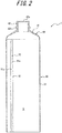
- a method for manufacturing the container main body 1 for example, a tube body 30, in which the container space S for the contents is defined, and a head 40 may be assembled for formation of the container main body 1, as illustrated in FIG. 2 .
- the head 40 is provided with the mouth 42 which opens upward and to which the dispensing cap 2 can be mounted.
- the tube body 30 can be formed in a substantially cylindrical shape by, for example, rolling a laminated sheet 31, which has been molded into a band shape and which has a laminated structure, in a manner such that both edges 31a, 31b thereof are butted together in a butted portion 32 and by performing welding at the butted portion 32 by means, such as high-frequency seals or heat seals.
- the tube body 30 has a substantially cylindrical shape
- the tube body 30 may have any shape that is substantially tubular, such as a substantially elliptic cylindrical shape.
- the tube body 30 has an inner surface that is provided, along the butted portion 32, with a reinforcing tape 35.
- the head 40 includes a shoulder 41 formed in a truncated cone shape.
- the head 40 can be provided integrally and contiguously with the tube body 30, for example, with an outer circumferential edge of the shoulder 41 being welded to an inner circumferential surface at an upper end of the tube body 30 over an entire circumference thereof.
- the head 40 may also be integrally formed with the tube body 30 by placing the aforementioned tube body 30, along with a material for the head 40, in a mold and performing compression molding.
- the shoulder 41 has a central portion that is provided with the cylindrical mouth 42 protruding upward.
- the mouth 42 at a tip thereof, has an opening 42a that communicates with the container space S for the contents.
- the mouth 42 has an outer circumferential surface that is provided with an annular projection 42b for fitting the dispensing cap 2 to the mouth 42.
- the open end is closed by means, such as high-frequency seals or heat seals, so as to form the bottom 1b.
- the container main body 1 is formed.
- the laminated sheet 31 for the tube body 30 that constitutes the trunk 1a of the container main body 1 has a layer composition as illustrated in FIG. 4 . That is, the laminate sheet 31 for the container main body 1 includes, in order from the inner side which is the side closer to the container space S, an inner polyethylene-based resin layer 11, a dry laminate (DL) adhesive layer 23, a polyethylene terephthalate (PET) film layer 13, an extruded polyethylene (PE) layer 14, a polyolefin resin layer 15 made of a polyethylene (PE) film, an extruded polyethylene (PE) layer 16, an aluminum (AL) foil 17 as a barrier layer, a dry laminate (DL) adhesive layer 25, a high reflection layer 19 in which gravure printing is performed on an outer side of a PET film and aluminum is vapor-deposited on an inner side of the PET film, a dry laminate adhesive layer 27, an outer polyethylene-based resin layer 21, a dry laminate adhesive layer 29, and a high hardness protective layer 18. Additionally, other portions of the container main body
- the aluminum foil 17 functions as the barrier layer having light-shielding properties, oxygen barrier properties, and water vapor barrier properties. From the perspective of guaranteeing flexibility, restorability, or the like of the trunk 1a while guaranteeing required light-shielding properties, oxygen barrier properties, and water vapor barrier properties, the aluminum foil 17 preferably has a thickness in the range of 7 ⁇ m to 20 ⁇ m. In the present embodiment, the aluminum foil 17 has a thickness of approximately 12 ⁇ m. Additionally, as the barrier layer, a metal foil other than an aluminum foil (e.g., a gold foil, silver foil, platinum foil, copper foil, titanium foil, tin foil, etc.) may be also used.
- a metal foil other than an aluminum foil e.g., a gold foil, silver foil, platinum foil, copper foil, titanium foil, tin foil, etc.
- the high reflection layer 19 includes a base material made of the polyethylene terephthalate (PET) film, which has one side (i.e., an inner surface) on which an aluminum vapor-deposited film is formed and has another side (i.e., an outer surface) on which gravure printing is performed for decoration.
- PET polyethylene terephthalate
- the aluminum vapor-deposited film is formed on one side of the base material having a small surface roughness and therefore, has a similarly small surface roughness and cause a low degree of scattering of incident light; the aluminum vapor-deposited film can therefore provide a high light reflectance (glossiness) despite its small thickness.
- the base material has a thickness of approximately 12 ⁇ m
- the aluminum vapor-deposited film has a thickness of approximately 100 nm.
- the thickness of the aluminum vapor-deposited film is preferably 50 nm or greater so as to achieve a high reflectance (glossiness).
- any of other metal vapor-deposited films of gold, silver, platinum, zinc, nickel, or the like may be formed instead of the aluminum vapor-deposited film.
- the container main body 1 is allowed to have both decorativeness and glossy and shiny properties.
- the present applicant has conducted earnest studies and found that, when gravure printing is additionally performed on the aluminum vapor-deposited film, the aluminum vapor-deposited film can be deteriorated due to an organic solvent used in the gravure printing, thus sometimes resulting in a failure to achieve a desired reflectance. It is therefore necessary to form the aluminum vapor-deposited film and the decoration by gravure printing on different sides of the base material.
- the high reflection layer 19 is configured such that the decoration is provided by gravure printing on the outer side of the base material and that the aluminum vapor-deposited film is formed on the inner side of the base material.
- any of a variety of resin films other than the polyethylene terephthalate (PET) film may be used as the base material, in which the surface roughness of the metal vapor-deposited film only needs to be reduced.
- the surface roughness of the metal vapor-deposited film is preferably less than the surface roughness of the metal foil.
- the high reflection layer 19 is adhered to an outer surface of the aluminum foil 17 via the dry laminate (DL) adhesive layer 25.
- the dry laminate adhesive layer 25 is an adhesive layer used to bond, after an adhesive agent is applied to one film before lamination and the adhesive agent is dried, the one film to another film by pressure bonding.
- the outer polyethylene-based resin layer 21 in the present embodiment is made of linear low-density polyethylene (LLDPE) having flexibility, transparency, and sealing properties. Any of a variety of polyethylene resins other than LLDPE, such as low-density polyethylene (LDPE) or high-density polyethylene resin (HDPE), can be used as polyethylene used for the outer polyethylene-based resin layer 21.
- LLDPE linear low-density polyethylene
- HDPE high-density polyethylene resin
- the outer polyethylene-based resin layer 21 has a thickness of approximately 60 ⁇ m. As described later, by making the thickness of the outer polyethylene-based resin layer 21 greater than the thickness of the high hardness protective layer 18, when the both edges 31a, 31b (refer to FIG.
- both edges of the outer polyethylene-based resin layer 21 can be welded with a predetermined degree of strength. Accordingly, even if both edges of the high hardness protective layer 18 cannot be sealed together with a sufficient degree of strength due to, for example, a high melting point of the high hardness protective layer 18, it is possible to guarantee welding strength at a portion corresponding to the outer polyethylene-based resin layer 21, whereby defects, such as flexure of the butted portion 32 caused when welding between the both edges 31a, 31b peels off at the butted portion 32, may be prevented. Additionally, the outer polyethylene-based resin layer 21 is adhered to an outer surface of the high reflection layer 19 via the dry laminate adhesive layer 27.
- the high hardness protective layer 18 in the present embodiment constitutes an outermost layer of the laminate sheet 31, and is formed of a polyethylene terephthalate (PET) film having high hardness so as to prevent scratches or the like from being generated on an outer surface of the container main body 1.
- PET polyethylene terephthalate
- the thickness of the high hardness protective layer 18 is approximately 12 ⁇ m
- the PET film used as the high hardness protective layer 18 in the present embodiment has a pencil hardness of "H" obtained by the scratch hardness (pencil method) measurement defined by JIS K 5600-5-4.
- the thickness of the high hardness protective layer 18 is preferably 16 ⁇ m or less, and the thickness of the outer polyethylene-based resin layer 21 is preferably 30 ⁇ m or more.
- the inner polyethylene-based resin layer 11 in the present embodiment constitutes an innermost layer of the laminate sheet 31, and is made of linear low-density polyethylene (LLDPE) having flexibility, transparency, and sealing properties in the same manner as the outer polyethylene-based resin layer 21.
- LLDPE linear low-density polyethylene
- the inner polyethylene-based resin layer 11 has a thickness of approximately 80 ⁇ m. In this way, since a polyethylene-based resin having a low melting point is used for the innermost layer of the laminate sheet 31, the open end at the lower portion of the tube body 30 can be easily closed by means, such as high-frequency seals or heat seals, so as to form a bottom 1b.
- any of a variety of polyethylene-based resins other than LLDPE such as low-density polyethylene (LDPE) or high-density polyethylene resin (HDPE), can be used for the inner polyethylene-based resin layer 11.
- LLDPE low-density polyethylene
- HDPE high-density polyethylene resin
- the PET film layer 13 is adhered to an outer surface of the inner polyethylene-based resin layer 11 via the dry laminate adhesive layer 23.
- the PET film layer 13 has a thickness of approximately 12 ⁇ m.
- An anchor coat (AC) layer 13a for enhancing adhesive strength is applied to an outer surface of the PET film layer 13, and a laminated body of the inner polyethylene-based resin layer 11 and the PET film layer 13 as described above is adhered to the polyolefin resin layer 15 via the extruded polyethylene layer 14 as an adhesive layer.
- the extruded polyethylene layer 14 has a thickness of approximately 30 ⁇ m.
- the polyolefin resin layer 15 in the present embodiment is a film member formed of polyethylene (PE).
- PE polyethylene
- Examples of polyethylene used for the polyolefin resin layer 15 may include low-density polyethylene (LDPE), linear low-density polyethylene (LLDPE), and high-density polyethylene resin (HDPE).
- LDPE low-density polyethylene
- LLDPE linear low-density polyethylene
- HDPE high-density polyethylene resin
- Excellent squeeze properties may be imparted to the trunk 1a of the container main body 1 especially when LLDPE is used.
- the polyolefin resin layer 15 preferably has a thickness in the range of 60 ⁇ m to 200 ⁇ m. In the present embodiment, the thickness of the polyolefin resin layer 15 is approximately 100 ⁇ m.
- the thickness of the polyolefin resin layer 15 is not limited to the above embodiment, and polypropylene, which is a polyolefin resin other than polyethylene, or the like may also be used. Further, any of a variety of resins other than a polyolefin resin may also be used.
- An AC layer 17a is applied to an inner surface of the aluminum foil 17 in a laminate body of the aluminum foil 17, the high reflection layer 19, the outer polyethylene-based resin layer 21, and the high hardness protective layer 18. Then, these are adhered to a laminate body of the inner polyethylene-based resin layer 11, the PET film layer 13, and the polyolefin resin layer 15 via the extruded polyethylene layer 16 as an adhesive layer.
- the extruded polyethylene layer 16 has a thickness of approximately 30 ⁇ m.
- the reinforcing tape 35 As illustrated in FIG. 2 and FIG. 3 , the reinforcing tape 35 is provided on the inner surface of the tube body 30 in a manner such that the reinforcing tape 35 extends along the butted portion 32 in a band shape in a vertical direction.
- the reinforcing tape 35 in the present embodiment has a layer composition as illustrated in FIG. 5 .
- the reinforcing tape 35 includes, in order from the inner side which is the side closer to the container space S, an inner reinforcing resin layer 51, a dry laminate (DL) adhesive layer 61, a polyethylene terephthalate (PET) film layer 53, a dry laminate (DL) adhesive layer 63, an aluminum (AL) foil 55, an extruded polyethylene (PE) layer 57, and an outer reinforcing resin layer 59.
- DL dry laminate
- PET polyethylene terephthalate
- DL dry laminate
- AL aluminum
- PE extruded polyethylene
- PE extruded polyethylene
- the inner reinforcing resin layer 51 in the present embodiment is made of linear low-density polyethylene (LLDPE). Any of a variety of polyethylene-based resins other than LLDPE, such as low-density polyethylene (LDPE) or high-density polyethylene resin (HDPE), can be used for the inner reinforcing resin layer 51.
- LLDPE linear low-density polyethylene
- HDPE high-density polyethylene resin
- the inner reinforcing resin layer 51 has a thickness of approximately 80 ⁇ m.
- a PET film layer 53 is adhered to an outer surface of the inner reinforcing resin layer 51 via a dry laminate adhesive layer 61. Since the PET film layer 53 is included in the reinforcing tape 35, strength of the reinforcing tape 35 can be increased, and it can be further ensured that joining between the both edges 31a, 31b at the butted portion 32 is reinforced. In the present embodiment, the PET film layer 53 has a thickness of approximately 12 ⁇ m.
- An aluminum (AL) foil 55 is adhered to an outer surface of the PET film layer 53 via a dry laminate adhesive layer 63.
- the aluminum foil 55 functions as a barrier layer having light shielding properties, oxygen barrier properties, and water vapor barrier properties. That is, even if joining between the both edges 31a, 31b at the butted portion 32 peels off, the contents contained in the container space S of the container main body 1 are prevented from undergoing deterioration and change in quality due to contact with light, oxygen, water vapor, or the like.
- the thickness of the aluminum foil 55 is preferably in the range of 7 ⁇ m to 20 ⁇ m from the perspective of properly maintaining flexibility of the trunk 1a while guaranteeing the necessary light-shielding, oxygen-barrier and water vapor-barrier properties.
- the aluminum foil 55 has a thickness of approximately 12 ⁇ m.
- a metal foil other than an aluminum foil e.g., a gold foil, silver foil, platinum foil, copper foil, titanium foil, tin foil, etc. may be also used.
- An anchor coat (AC) layer 65 for increasing adhesive strength is applied to an outer surface of the aluminum foil 55, and these are adhered to an outer reinforcing resin layer 59 via an extruded polyethylene layer 57 as an adhesive layer.
- the extruded polyethylene layer 57 has a thickness of approximately 30 ⁇ m.
- the outer reinforcing resin layer 59 in the present embodiment is made of linear low-density polyethylene (LLDPE). Any of a variety of polyethylene-based resins other than LLDPE, such as low-density polyethylene (LDPE) or high-density polyethylene resin (HDPE), can be used for the outer reinforcing resin layer 59.
- LLDPE linear low-density polyethylene
- HDPE high-density polyethylene resin
- the outer reinforcing resin layer 59 has a thickness of approximately 60 ⁇ m and is colored in white.
- the reinforcing tape 35 in the present embodiment extends along the butted portion 32 from one end of the tube body 30 that is connected to the head 40 of the tube body 30 to another end of the tube body 30 that is closed so as to form the bottom 1b.
- the reinforcing tape 35 is bonded to the inner surface of the tube body 30 over the entire range of the butted portion 32 in a longitudinal direction across the both edges 31a, 31b.
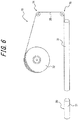
- the reinforcing tape 35 described above can be fed to the laminated sheet 31 using a feeding apparatus 70 for the reinforcing tape 35 as illustrated in FIG. 6 .
- the feeding apparatus 70 includes a roll 72 for feeding the reinforcing tape 35 that has the laminated structure illustrated in FIG. 5 in advance, and feeds the reinforcing tape 35 fed from the roll 72 toward an inward side of the laminated sheet 31 through a guide roller 74 and a guide roller 75.
- the reinforcing tape 35 After being fed onto the inner surface of the laminate sheet 31 using the aforementioned feeding apparatus 70, the reinforcing tape 35 is pressed against the inner surface of the laminate sheet 31 while being heated to a predetermined temperature by, for example, a molding apparatus which is not illustrated, so as to be welded to the butted portion 32 of the both edges 31a, 31b.
- the reinforcing tape 35 is formed so that the thickness of each of the outer reinforcing resin layer 59 and the inner reinforcing resin layer 51 is greater than the thickness of any other intermediate layer, part of the outer reinforcing resin layer 59 and part of the inner reinforcing resin layer 51 are pressed out laterally (i.e., in a circumferential direction in FIG.
- the pressed part of the outer reinforcing resin layer 59 and the pressed part of the inner reinforcing resin layer 51 weld to each other so as to cover end portions of the other intermediate layers in the circumferential direction and to be welded to the inner surface of the laminate sheet 31.
- the aluminum foil 55 and the like illustrated in FIG. 5 in the circumferential direction are covered by the outer reinforcing resin layer 59 and the inner reinforcing resin layer 51, the aluminum foil 55 and the like are isolated from the container space S. This can prevent direct contact of the contents in the container space S with the aluminum foil 55 and the like, thereby preventing degradation in quality due to discoloration or the like of the contents.
- the laminated sheet 31 to which the reinforcement tape 35 has been welded is cut in the longitudinal direction so as to form the tube body 30.
- the outer reinforcing resin layer 59 is colored in white so as to have a color different from color(s) of other layers (e.g., the inner reinforcing resin layer 51 and the aluminum foil 55). Due to the above configuration, the outer reinforcing resin layer 59 facing an inner circumferential surface of the laminate sheet 31 among the constituent layers of the reinforcing tape 35 may have a color different from color(s) of the other layers, including the inner reinforcing resin layer 51 and the aluminum foil 55.
- the dispensing cap 2 is provided with the dispensing orifice through which the contents in the container space S of the container main body 1 are dispensed to the outside, and is fitted to the annular projection 42b provided in the mouth 42 of the container main body 1 by undercut engagement. Further, the lid 3 is provided above the dispensing cap 2 so as to cover the dispensing orifice.
- the lid 3 is integrally formed with the dispensing cap 2 via a hinge which is not illustrated, and the dispensing orifice can be opened or can be closed by the lid 3 by rotating the lid 3 about the hinge.
- fitting of the dispensing cap 2 to the container main body 1 is not limited to the aforementioned undercut engagement, and the dispensing cap 2 may also be configured to be fitted to a male screw portion formed in the mouth 42 of the container main body 1 by screwing engagement.
- the lid 3 is rotated about the hinge so as to bring the dispensing orifice into an open state, and subsequently, the tube container 100 is repositioned so that the dispensing orifice faces an application area, and the trunk 1a is put under pressure (i.e., squeezed). By doing so, pressure in the container space S of the container main body 1 increases, and the contents are dispensed to the outside through the dispensing orifice.
- the laminate sheet 31 for the tube body 30 that constitutes the trunk 1a of the container main body 1 includes the aluminum foil 17 as the barrier layer and the polyolefin resin layer 15 whose thickness is greater than the thickness of the high reflection layer 19 provided to improve glossy and shiny properties. Accordingly, in conjunction with releasing of the pressure on the trunk 1a, the trunk 1a returns to the original shape, a shape before the pressure is put, due to excellent restorability against deformation that is attributed to its material properties.
- the tube container 100 includes the tube body 30 that defines the container space S for contents and that has the laminated structure of a plurality of materials, wherein the tube body 30 includes: the cylindrical laminated sheet 31 in which the both edges 31a, 31b of the sheet are butted together; and the reinforcing tape portion (reinforcing tape 35) provided on the inner surface of the laminated sheet 31 along the butted portion 32, and the laminate sheet 31 includes the high hardness protective layer 18 constituting the outermost layer, the outer polyethylene-based resin layer 21 formed on the inner side of the high hardness protective layer 18, and the inner polyethylene-based resin layer 11 constituting the innermost layer, the high hardness protective layer 18 having a pencil hardness of 3B or greater than 3B, and wherein the reinforcing tape portion (reinforcing tape 35) includes the polyethylene-based resin layer (outer reinforcing resin layer 59) as the outermost layer abutting against the inner surface of the
- the innermost layer of the laminate sheet 31 and the innermost layer of the reinforcing tape 35 are both polyethylene-based resin layers, when the open end at the lower portion of the tube body 30 is closed by means, such as high-frequency seals or heat seals, so as to form the bottom 1b, the open end including a portion corresponding to the reinforcing tape 35 is easily sealed.
- the outer circumferential edge of the shoulder 41 can be easily welded to the inner circumferential surface at the upper end of the tube body 30 over the entire circumference thereof.
- the high hardness protective layer 18 is configured to contain polyethylene terephthalate.
- polyethylene terephthalate having a predetermined hardness is used as the high hardness protective layer 18 constituting the outermost layer of the tube container 100, and generation of scratches on the surface of the tube container 100 can be effectively prevented.
- the outer polyethylene-based resin layer 21 is configured to have a thickness greater than a thickness of the high hardness protective layer 18.
- the outer polyethylene-based resin layer 21 is configured to have a thickness of 30 ⁇ m or more, and the high hardness protective layer 18 is configured to have a thickness of 16 ⁇ m or less.
- the outermost layer and the innermost layer of the reinforcing tape portion are each configured to have a thickness greater than a thickness of any other intermediate layer.
- the outermost layer of the reinforcing tape portion (reinforcing tape 35) is configured to have a color different from color(s) of other constituent layers of the reinforcing tape portion.
- the laminated sheet 31 and the reinforcing tape portion (reinforcing tape 35) are each configured to include a barrier layer having a metal foil.
- the metal foil (aluminum foil 55) included in the reinforcing tape 35 can prevent permeation of light, oxygen, water vapor, or the like, and the contents contained in the container space S of the container main body 1 are prevented from undergoing deterioration and change in quality due to contact with light, oxygen, water vapor, or the like.
- PET polyethylene terephthalate
- the present disclosure is not limited to this embodiment. Any film having a predetermined hardness other than a PET film may be used as the high hardness protective layer 18.
- the thickness of the outer polyethylene-based resin layer 21 is configured to be greater than the thickness of the high hardness protective layer 18, the present disclosure is not limited to this embodiment.
- the reinforcing tape 35 only needs to provide enough reinforcement to prevent leakage of the contents from the butted portion 32 of the laminate sheet 31.
- the outermost layer and the innermost layer of the reinforcing tape 35 are each configured to have a thickness greater than a thickness of any other intermediate layer, the present disclosure is not limited to this embodiment.
- Other means may also be used to configure each intermediate layer not to contact the contents, or alternatively, it is not necessarily needed to configure each intermediate layer not to contact the contents depending on the contents.
- the outer reinforcing resin layer 59 of the reinforcing tape 35 is configured to be colored in white
- the present disclosure is not limited to this embodiment.
- the outer reinforcing resin layer 59 may be colored in a color other than white that is different from other layers of the reinforcing tape 35.
- the outer reinforcing resin layer 59 does not necessarily need to be colored.
- the laminate sheet 31 and the reinforcing tape 35 are each configured to include the barrier layer having the aluminum foil 17, 55, the present disclosure is not limited to this embodiment. Only the laminate sheet 31 may be configured to include the barrier layer, or alternatively, it is not necessarily needed for either of the laminate sheet 31 and the reinforcing tape 35 to include the barrier layer depending on the contents.
- the high reflection layer 19 is configured in a manner such that the decoration is provided by gravure printing on the outer surface of the base material and that the aluminum vapor-deposited film is formed on the inner surface of the base material, the present disclosure is not limited to this embodiment.
- the decoration by printing does not necessarily need to be provided on the outer surface of the base material, in which case the aluminum vapor-deposited film may be formed on the outer surface of the base material. Further, the aluminum vapor-deposited film may be formed on both sides of the base material. Further, the laminated sheet 31 does not necessarily need to include the high reflection layer 19.
- gravure printing may be performed on the inner surface of the high hardness protective layer 18.
- Example 1 the layer composition illustrated in FIG. 4 (Example 1), and a layer composition (Comparative Example 1) obtained by excluding the outer high hardness protective layer 18 and the dry laminate (DL) adhesive layer 29 from FIG. 4 were prepared, and a pencil hardness measurement and a wear resistance test were conducted for each layer composition.
- Example 1 summarizes, for each of Example 1 and Comparative Example 1, respective results of the pencil hardness measurement and the wear resistance test.
- Pencil hardness was measured by the scratch hardness (pencil method) measurement defined by JIS K 5600-5-4. In wear resistance tests, reciprocating motion was made 100 times while a load of 1.8 kgf was applied between a filter paper and the outermost layer of each laminated sheet, and it was evaluated whether scratches beyond the standard occurred in the outermost layer of the laminated sheet.
- Example 1 Comparative Example 1 Pencil hardness H Less than 6B Wear resistance test Good Bad
- Example 1 Example 2
- Example 3 Thickness of high hardness protective layer 12 16 20 Thickness of outer polyethylene-based resin layer 60 60 60 Joining strength at butted portion Good Good Bad
- Example 1 and Example 2 the thickness (60 ⁇ m) of the outer polyethylene-based resin layer 21 is sufficiently greater than the thickness (12 ⁇ m or 16 ⁇ m) of the high hardness protective layer 18, joining strength at the entire butted portion 32 is maintained in a good condition due to joining at the portion corresponding to the outer polyethylene-based resin layer 21 even when joining strength at the high hardness protective layer 18 is not sufficient.
- Example 3 because a difference between the thickness (60 ⁇ m) of the outer polyethylene-based resin layer 21 and the thickness (20 ⁇ m) of the high hardness protective layer 18 is small, when joining strength at the high hardness protective layer 18 is not sufficient, it is considered that joining strength at the entire butted portion 32 cannot be maintained in a good condition by joining at the portion corresponding to the outer polyethylene-based resin layer 21. Additionally, it has been also turned out that the thickness of the outer polyethylene-based resin layer 21 is preferably 30 ⁇ m or more.
- the present disclosure enables proposal of the tube container 100 in which generation of scratches on the surface of the container can be prevented.
Landscapes
- Engineering & Computer Science (AREA)
- Mechanical Engineering (AREA)
- Tubes (AREA)
- Laminated Bodies (AREA)
Abstract
Description
- This application claims the priority to
Japanese Patent Application No. 2018-161743, filed on August 30, 2018 - The present disclosure relates to a tube container that can dispense contents when being pressed on a trunk.
- Tube containers in which cosmetic products, toothpaste, pharmaceutical agents, seasoning, or the like can be filled as contents and which can dispense the contents when being pressed on trunks of the containers are desired to have good light-shielding properties and good gas barrier properties so as to prevent deterioration of the contents, while still enjoying enhanced aesthetic appearances of the containers.
- For example, Patent Literature 1 (PTL1) describes a tube container that includes a metal vapor-deposited layer and a barrier layer and that is designed to have glossy properties, in addition to light-shielding properties and gas barrier properties.
- PTL 1:
JP 2017-114508 A - In the tube container described in
PTL 1, however, scratches are sometimes generated on a surface of the container during or after manufacturing of the container, although the glossy properties can be improved, and there is still room for improvement in terms of enhanced aesthetic appearance of the container. - It would be helpful to provide a tube container in which generation of scratches on the surface of the container can be prevented.
- A tube container according to an embodiment of the present disclosure includes a tube body that defines a container space for contents and that has a laminated structure of a plurality of materials, wherein
the tube body includes: - a cylindrical laminated sheet in which both edges of the sheet are butted together; and
- a reinforcing tape portion provided on an inner surface of the laminated sheet along a butted portion, and
- the laminate sheet includes a high hardness protective layer constituting an outermost layer, an outer polyethylene-based resin layer formed on an inner side of the high hardness protective layer, and an inner polyethylene-based resin layer constituting an innermost layer, the high hardness protective layer having a pencil hardness of 3B or greater than 3B, and wherein
- the reinforcing tape portion includes a polyethylene-based resin layer as an outermost layer abutting against the inner surface of the laminate sheet.
- In a preferred embodiment of the present tube container configured as above, the high hardness protective layer contains polyethylene terephthalate.
- In another preferred embodiment of the present tube container configured as above, the outer polyethylene-based resin layer has a thickness greater than a thickness of the high hardness protective layer.
- In still another preferred embodiment of the present tube container configured as above, the outer polyethylene-based resin layer has a thickness of 30 µm or more, and the high hardness protective layer has a thickness of 16 µm or less.
- In still another preferred embodiment of the present tube container configured as above, the outermost layer and an innermost layer of the reinforcing tape portion each have a thickness greater than a thickness of any other intermediate layer of the reinforcing tape portion.
- In still another preferred embodiment of the present tube container configured as above, the outermost layer of the reinforcing tape portion has a color different from a color of other constituent layers of the reinforcing tape portion.
- In still another preferred embodiment of the present tube container configured as above, the laminated sheet and the reinforcing tape portion each includes a barrier layer having a metal foil.
- The present disclosure provides a tube container in which generation of scratches on the surface of the container can be prevented.
- In the accompanying drawings:
-
FIG. 1 is a front view illustrating a tube container according to an embodiment of the present disclosure; -
FIG. 2 is a sectional front view illustrating a container body (having no seal on a bottom) that constitutes the tube container according to the embodiment of the present disclosure; -
FIG. 3 is an enlarged sectional plan view illustrating a butted portion and a reinforcing tape portion of the container body constituting the tube container according to the embodiment of the present disclosure; -
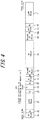
FIG. 4 illustrates a layer composition of a laminate sheet in the tube container according to the embodiment of the present disclosure; -
FIG. 5 illustrates a layer composition of a reinforcing tape in the tube container according to the embodiment of the present disclosure; and -
FIG. 6 schematically illustrates a feeding apparatus for feeding the reinforcing tape. - The present disclosure will be described in more detail below with reference to the drawings.
-
FIG. 1 is a front view illustrating a configuration of atube container 100 that is an embodiment of the present disclosure. Thetube container 100 includes a containermain body 1 that defines a container space S (refer toFIG. 2 ) for contents, a dispensingcap 2 that is fitted to a mouth 42 (refer toFIG. 2 ) of the containermain body 1, and alid 3 that closes a dispensing orifice of the dispensingcap 2. It should be noted that in the present specification, claims, abstract, and drawings, a side on which thelid 3 is located is defined as an upward direction (an upper side inFIG. 1 ), and a side on which the containermain body 1 is located is defined as a downward direction (a lower side inFIG. 1 ). Further, in descriptions regarding layer compositions for the containermain body 1, a side on which the container space S is located is defined as an inner side, and a side on which an outer circumferential surface of the containermain body 1 is located is defined as an outer side. - First, the container
main body 1 will be described. As illustrated inFIG. 1 , the containermain body 1 defines the container space S (refer toFIG. 2 ) for the contents, and includes atrunk 1a that, when being pressed, causes the contents to be dispensed, and abottom 1b that closes a lower end of thetrunk 1a. As a method for manufacturing the containermain body 1, for example, atube body 30, in which the container space S for the contents is defined, and ahead 40 may be assembled for formation of the containermain body 1, as illustrated inFIG. 2 . Thehead 40 is provided with themouth 42 which opens upward and to which the dispensingcap 2 can be mounted. - The
tube body 30 can be formed in a substantially cylindrical shape by, for example, rolling a laminatedsheet 31, which has been molded into a band shape and which has a laminated structure, in a manner such that bothedges portion 32 and by performing welding at the buttedportion 32 by means, such as high-frequency seals or heat seals. Although in the present embodiment thetube body 30 has a substantially cylindrical shape, thetube body 30 may have any shape that is substantially tubular, such as a substantially elliptic cylindrical shape. - Further, as illustrated in
FIG. 2 andFIG. 3 , to reinforce joining at the buttedportion 32 of the laminatedsheet 31, thetube body 30 has an inner surface that is provided, along the buttedportion 32, with a reinforcingtape 35. - In the present embodiment, the
head 40 includes ashoulder 41 formed in a truncated cone shape. Thehead 40 can be provided integrally and contiguously with thetube body 30, for example, with an outer circumferential edge of theshoulder 41 being welded to an inner circumferential surface at an upper end of thetube body 30 over an entire circumference thereof. Thehead 40 may also be integrally formed with thetube body 30 by placing theaforementioned tube body 30, along with a material for thehead 40, in a mold and performing compression molding. - The
shoulder 41 has a central portion that is provided with thecylindrical mouth 42 protruding upward. Themouth 42, at a tip thereof, has an opening 42a that communicates with the container space S for the contents. Themouth 42 has an outer circumferential surface that is provided with anannular projection 42b for fitting the dispensingcap 2 to themouth 42. - After filling the contents into the container space S through an open end at a lower portion of the
tube body 30 having such a substantially cylindrical shape, the open end is closed by means, such as high-frequency seals or heat seals, so as to form thebottom 1b. Thus, the containermain body 1 is formed. - In the present embodiment, the laminated
sheet 31 for thetube body 30 that constitutes thetrunk 1a of the containermain body 1 has a layer composition as illustrated inFIG. 4 . That is, thelaminate sheet 31 for the containermain body 1 includes, in order from the inner side which is the side closer to the container space S, an inner polyethylene-basedresin layer 11, a dry laminate (DL)adhesive layer 23, a polyethylene terephthalate (PET)film layer 13, an extruded polyethylene (PE)layer 14, apolyolefin resin layer 15 made of a polyethylene (PE) film, an extruded polyethylene (PE)layer 16, an aluminum (AL)foil 17 as a barrier layer, a dry laminate (DL)adhesive layer 25, ahigh reflection layer 19 in which gravure printing is performed on an outer side of a PET film and aluminum is vapor-deposited on an inner side of the PET film, a dry laminateadhesive layer 27, an outer polyethylene-basedresin layer 21, a dry laminateadhesive layer 29, and a high hardnessprotective layer 18. Additionally, other portions of the containermain body 1 than thetrunk 1a may have the same layer composition as thetrunk 1a, or may have a composition in which some layers are omitted or some layers are added. - The
aluminum foil 17 functions as the barrier layer having light-shielding properties, oxygen barrier properties, and water vapor barrier properties. From the perspective of guaranteeing flexibility, restorability, or the like of thetrunk 1a while guaranteeing required light-shielding properties, oxygen barrier properties, and water vapor barrier properties, thealuminum foil 17 preferably has a thickness in the range of 7 µm to 20 µm. In the present embodiment, thealuminum foil 17 has a thickness of approximately 12 µm. Additionally, as the barrier layer, a metal foil other than an aluminum foil (e.g., a gold foil, silver foil, platinum foil, copper foil, titanium foil, tin foil, etc.) may be also used. - The
high reflection layer 19 includes a base material made of the polyethylene terephthalate (PET) film, which has one side (i.e., an inner surface) on which an aluminum vapor-deposited film is formed and has another side (i.e., an outer surface) on which gravure printing is performed for decoration. In the present embodiment, the aluminum vapor-deposited film is formed on one side of the base material having a small surface roughness and therefore, has a similarly small surface roughness and cause a low degree of scattering of incident light; the aluminum vapor-deposited film can therefore provide a high light reflectance (glossiness) despite its small thickness. In the present embodiment, the base material has a thickness of approximately 12 µm, and the aluminum vapor-deposited film has a thickness of approximately 100 nm. The thickness of the aluminum vapor-deposited film is preferably 50 nm or greater so as to achieve a high reflectance (glossiness). Additionally, any of other metal vapor-deposited films of gold, silver, platinum, zinc, nickel, or the like may be formed instead of the aluminum vapor-deposited film. - In the present embodiment and by performing gravure printing on the outer surface of the base material and by forming the aluminum vapor-deposited film on the inner surface of the base material, the container
main body 1 is allowed to have both decorativeness and glossy and shiny properties. The present applicant has conducted earnest studies and found that, when gravure printing is additionally performed on the aluminum vapor-deposited film, the aluminum vapor-deposited film can be deteriorated due to an organic solvent used in the gravure printing, thus sometimes resulting in a failure to achieve a desired reflectance. It is therefore necessary to form the aluminum vapor-deposited film and the decoration by gravure printing on different sides of the base material. Further, formation of the aluminum vapor-deposited film on the outer side of the base material degrades visibility of the decoration formed by gravure printing on the inner side of the base material. For the above reasons, thehigh reflection layer 19 is configured such that the decoration is provided by gravure printing on the outer side of the base material and that the aluminum vapor-deposited film is formed on the inner side of the base material. Additionally, any of a variety of resin films other than the polyethylene terephthalate (PET) film may be used as the base material, in which the surface roughness of the metal vapor-deposited film only needs to be reduced. The surface roughness of the metal vapor-deposited film is preferably less than the surface roughness of the metal foil. - In the present embodiment, as illustrated in
FIG. 4 , thehigh reflection layer 19 is adhered to an outer surface of thealuminum foil 17 via the dry laminate (DL)adhesive layer 25. The dry laminateadhesive layer 25 is an adhesive layer used to bond, after an adhesive agent is applied to one film before lamination and the adhesive agent is dried, the one film to another film by pressure bonding. - The outer polyethylene-based
resin layer 21 in the present embodiment is made of linear low-density polyethylene (LLDPE) having flexibility, transparency, and sealing properties. Any of a variety of polyethylene resins other than LLDPE, such as low-density polyethylene (LDPE) or high-density polyethylene resin (HDPE), can be used as polyethylene used for the outer polyethylene-basedresin layer 21. In the present embodiment, the outer polyethylene-basedresin layer 21 has a thickness of approximately 60 µm. As described later, by making the thickness of the outer polyethylene-basedresin layer 21 greater than the thickness of the high hardnessprotective layer 18, when the bothedges FIG. 3 ) of thelaminate sheet 31 are butted together for high-frequency sealing or heat-sealing, both edges of the outer polyethylene-basedresin layer 21 can be welded with a predetermined degree of strength. Accordingly, even if both edges of the high hardnessprotective layer 18 cannot be sealed together with a sufficient degree of strength due to, for example, a high melting point of the high hardnessprotective layer 18, it is possible to guarantee welding strength at a portion corresponding to the outer polyethylene-basedresin layer 21, whereby defects, such as flexure of the buttedportion 32 caused when welding between the bothedges portion 32, may be prevented. Additionally, the outer polyethylene-basedresin layer 21 is adhered to an outer surface of thehigh reflection layer 19 via the dry laminateadhesive layer 27. - The high hardness
protective layer 18 in the present embodiment constitutes an outermost layer of thelaminate sheet 31, and is formed of a polyethylene terephthalate (PET) film having high hardness so as to prevent scratches or the like from being generated on an outer surface of the containermain body 1. In the present embodiment, the thickness of the high hardnessprotective layer 18 is approximately 12 µm, The PET film used as the high hardnessprotective layer 18 in the present embodiment has a pencil hardness of "H" obtained by the scratch hardness (pencil method) measurement defined by JIS K 5600-5-4. It should be noted that the applicant have conducted earnest studies and achieved the result that, when the pencil hardness of the high hardnessprotective layer 18 is "3B" or greater than "3B", scratches beyond the standard are not generated in later-described wear resistance tests. The high hardnessprotective layer 18 is adhered to an outer surface of the outer polyethylene-basedresin layer 21 via the dry laminateadhesive layer 29. - Additionally, to achieve optimal high frequency sealing or heat sealing by butting the both
edges aforementioned laminate sheet 31 together, the thickness of the high hardnessprotective layer 18 is preferably 16 µm or less, and the thickness of the outer polyethylene-basedresin layer 21 is preferably 30 µm or more. - The inner polyethylene-based
resin layer 11 in the present embodiment constitutes an innermost layer of thelaminate sheet 31, and is made of linear low-density polyethylene (LLDPE) having flexibility, transparency, and sealing properties in the same manner as the outer polyethylene-basedresin layer 21. In the present embodiment, the inner polyethylene-basedresin layer 11 has a thickness of approximately 80 µm. In this way, since a polyethylene-based resin having a low melting point is used for the innermost layer of thelaminate sheet 31, the open end at the lower portion of thetube body 30 can be easily closed by means, such as high-frequency seals or heat seals, so as to form a bottom 1b. Additionally, as is the case with the outer polyethylene-basedresin layer 21, any of a variety of polyethylene-based resins other than LLDPE, such as low-density polyethylene (LDPE) or high-density polyethylene resin (HDPE), can be used for the inner polyethylene-basedresin layer 11. - The
PET film layer 13 is adhered to an outer surface of the inner polyethylene-basedresin layer 11 via the dry laminateadhesive layer 23. In the present embodiment, thePET film layer 13 has a thickness of approximately 12 µm. - An anchor coat (AC)
layer 13a for enhancing adhesive strength is applied to an outer surface of thePET film layer 13, and a laminated body of the inner polyethylene-basedresin layer 11 and thePET film layer 13 as described above is adhered to thepolyolefin resin layer 15 via the extrudedpolyethylene layer 14 as an adhesive layer. In the present embodiment, the extrudedpolyethylene layer 14 has a thickness of approximately 30 µm. - The
polyolefin resin layer 15 in the present embodiment is a film member formed of polyethylene (PE). Examples of polyethylene used for thepolyolefin resin layer 15 may include low-density polyethylene (LDPE), linear low-density polyethylene (LLDPE), and high-density polyethylene resin (HDPE). Excellent squeeze properties may be imparted to thetrunk 1a of the containermain body 1 especially when LLDPE is used. From the perspective of guaranteeing flexibility, restorability, or the like of thetrunk 1a of the containermain body 1, thepolyolefin resin layer 15 preferably has a thickness in the range of 60 µm to 200 µm. In the present embodiment, the thickness of thepolyolefin resin layer 15 is approximately 100 µm. By thus forming the thickness of thepolyolefin resin layer 15 greater than the thickness of the barrier layer and thehigh reflection layer 19, restorability of thetrunk 1a is guaranteed. Additionally, the composition of thepolyolefin resin layer 15 is not limited to the above embodiment, and polypropylene, which is a polyolefin resin other than polyethylene, or the like may also be used. Further, any of a variety of resins other than a polyolefin resin may also be used. - An
AC layer 17a is applied to an inner surface of thealuminum foil 17 in a laminate body of thealuminum foil 17, thehigh reflection layer 19, the outer polyethylene-basedresin layer 21, and the high hardnessprotective layer 18. Then, these are adhered to a laminate body of the inner polyethylene-basedresin layer 11, thePET film layer 13, and thepolyolefin resin layer 15 via the extrudedpolyethylene layer 16 as an adhesive layer. In the present embodiment, the extrudedpolyethylene layer 16 has a thickness of approximately 30 µm. - Next, the reinforcing
tape 35 will be described. As illustrated inFIG. 2 andFIG. 3 , the reinforcingtape 35 is provided on the inner surface of thetube body 30 in a manner such that the reinforcingtape 35 extends along the buttedportion 32 in a band shape in a vertical direction. The reinforcingtape 35 in the present embodiment has a layer composition as illustrated inFIG. 5 . That is, the reinforcingtape 35 includes, in order from the inner side which is the side closer to the container space S, an inner reinforcingresin layer 51, a dry laminate (DL)adhesive layer 61, a polyethylene terephthalate (PET)film layer 53, a dry laminate (DL)adhesive layer 63, an aluminum (AL)foil 55, an extruded polyethylene (PE)layer 57, and an outer reinforcingresin layer 59. - The inner reinforcing
resin layer 51 in the present embodiment is made of linear low-density polyethylene (LLDPE). Any of a variety of polyethylene-based resins other than LLDPE, such as low-density polyethylene (LDPE) or high-density polyethylene resin (HDPE), can be used for the inner reinforcingresin layer 51. In the present embodiment, the inner reinforcingresin layer 51 has a thickness of approximately 80 µm. - A
PET film layer 53 is adhered to an outer surface of the inner reinforcingresin layer 51 via a dry laminateadhesive layer 61. Since thePET film layer 53 is included in the reinforcingtape 35, strength of the reinforcingtape 35 can be increased, and it can be further ensured that joining between the bothedges portion 32 is reinforced. In the present embodiment, thePET film layer 53 has a thickness of approximately 12 µm. - An aluminum (AL)
foil 55 is adhered to an outer surface of thePET film layer 53 via a dry laminateadhesive layer 63. Thealuminum foil 55 functions as a barrier layer having light shielding properties, oxygen barrier properties, and water vapor barrier properties. That is, even if joining between the bothedges portion 32 peels off, the contents contained in the container space S of the containermain body 1 are prevented from undergoing deterioration and change in quality due to contact with light, oxygen, water vapor, or the like. The thickness of thealuminum foil 55 is preferably in the range of 7 µm to 20 µm from the perspective of properly maintaining flexibility of thetrunk 1a while guaranteeing the necessary light-shielding, oxygen-barrier and water vapor-barrier properties. In the present embodiment, thealuminum foil 55 has a thickness of approximately 12 µm. Additionally, as the barrier layer, a metal foil other than an aluminum foil (e.g., a gold foil, silver foil, platinum foil, copper foil, titanium foil, tin foil, etc.) may be also used. - An anchor coat (AC)
layer 65 for increasing adhesive strength is applied to an outer surface of thealuminum foil 55, and these are adhered to an outer reinforcingresin layer 59 via an extrudedpolyethylene layer 57 as an adhesive layer. In the present embodiment, the extrudedpolyethylene layer 57 has a thickness of approximately 30 µm. - The outer reinforcing
resin layer 59 in the present embodiment is made of linear low-density polyethylene (LLDPE). Any of a variety of polyethylene-based resins other than LLDPE, such as low-density polyethylene (LDPE) or high-density polyethylene resin (HDPE), can be used for the outer reinforcingresin layer 59. In the present embodiment, the outer reinforcingresin layer 59 has a thickness of approximately 60 µm and is colored in white. - As illustrated in
FIG. 2 , the reinforcingtape 35 in the present embodiment extends along the buttedportion 32 from one end of thetube body 30 that is connected to thehead 40 of thetube body 30 to another end of thetube body 30 that is closed so as to form the bottom 1b. The reinforcingtape 35 is bonded to the inner surface of thetube body 30 over the entire range of the buttedportion 32 in a longitudinal direction across the bothedges portion 32 of thelaminate sheet 31 is reinforced by the reinforcingtape 35, and further, even if joining between the bothedges portion 32 peels off, the portion remains held by the reinforcingtape 35, and leakage of the contents from the portion may be prevented. - The reinforcing
tape 35 described above can be fed to thelaminated sheet 31 using afeeding apparatus 70 for the reinforcingtape 35 as illustrated inFIG. 6 . Thefeeding apparatus 70 includes aroll 72 for feeding the reinforcingtape 35 that has the laminated structure illustrated inFIG. 5 in advance, and feeds the reinforcingtape 35 fed from theroll 72 toward an inward side of thelaminated sheet 31 through aguide roller 74 and aguide roller 75. - After being fed onto the inner surface of the
laminate sheet 31 using theaforementioned feeding apparatus 70, the reinforcingtape 35 is pressed against the inner surface of thelaminate sheet 31 while being heated to a predetermined temperature by, for example, a molding apparatus which is not illustrated, so as to be welded to the buttedportion 32 of the bothedges FIG. 5 , the reinforcingtape 35 is formed so that the thickness of each of the outer reinforcingresin layer 59 and the inner reinforcingresin layer 51 is greater than the thickness of any other intermediate layer, part of the outer reinforcingresin layer 59 and part of the inner reinforcingresin layer 51 are pressed out laterally (i.e., in a circumferential direction inFIG. 3 ) beyond other intermediate layers, and the pressed part of the outer reinforcingresin layer 59 and the pressed part of the inner reinforcingresin layer 51 weld to each other so as to cover end portions of the other intermediate layers in the circumferential direction and to be welded to the inner surface of thelaminate sheet 31. Thus, because the end portions of thealuminum foil 55 and the like illustrated inFIG. 5 in the circumferential direction are covered by the outer reinforcingresin layer 59 and the inner reinforcingresin layer 51, thealuminum foil 55 and the like are isolated from the container space S. This can prevent direct contact of the contents in the container space S with thealuminum foil 55 and the like, thereby preventing degradation in quality due to discoloration or the like of the contents. Thelaminated sheet 31 to which thereinforcement tape 35 has been welded is cut in the longitudinal direction so as to form thetube body 30. - Further, in the present embodiment, the outer reinforcing
resin layer 59 is colored in white so as to have a color different from color(s) of other layers (e.g., the inner reinforcingresin layer 51 and the aluminum foil 55). Due to the above configuration, the outer reinforcingresin layer 59 facing an inner circumferential surface of thelaminate sheet 31 among the constituent layers of the reinforcingtape 35 may have a color different from color(s) of the other layers, including the inner reinforcingresin layer 51 and thealuminum foil 55. It can therefore be easily confirmed whether lateral sides of thealuminum foil 55 and the like are sufficiently covered by the outer reinforcingresin layer 59 or the like by visually checking thelaminated sheet 31 with thereinforcement tape 35 from the inner side and confirming how much of the outer reinforcingresin layer 59 protrudes laterally (i.e., in the circumferential direction). - Next, the dispensing
cap 2 will be described. The dispensingcap 2 is provided with the dispensing orifice through which the contents in the container space S of the containermain body 1 are dispensed to the outside, and is fitted to theannular projection 42b provided in themouth 42 of the containermain body 1 by undercut engagement. Further, thelid 3 is provided above the dispensingcap 2 so as to cover the dispensing orifice. Thelid 3 is integrally formed with the dispensingcap 2 via a hinge which is not illustrated, and the dispensing orifice can be opened or can be closed by thelid 3 by rotating thelid 3 about the hinge. Additionally, fitting of the dispensingcap 2 to the containermain body 1 is not limited to the aforementioned undercut engagement, and the dispensingcap 2 may also be configured to be fitted to a male screw portion formed in themouth 42 of the containermain body 1 by screwing engagement. - To dispense the contents from the
tube container 100 configured as described above, thelid 3 is rotated about the hinge so as to bring the dispensing orifice into an open state, and subsequently, thetube container 100 is repositioned so that the dispensing orifice faces an application area, and thetrunk 1a is put under pressure (i.e., squeezed). By doing so, pressure in the container space S of the containermain body 1 increases, and the contents are dispensed to the outside through the dispensing orifice. - After dispensing a required amount of the contents, pressure on the
trunk 1a is released. By doing so, pressure in the container space S is returned to outer air pressure, and thetrunk 1a of the containermain body 1 returns to its original shape by its own restoring force. Thelaminate sheet 31 for thetube body 30 that constitutes thetrunk 1a of the containermain body 1 includes thealuminum foil 17 as the barrier layer and thepolyolefin resin layer 15 whose thickness is greater than the thickness of thehigh reflection layer 19 provided to improve glossy and shiny properties. Accordingly, in conjunction with releasing of the pressure on thetrunk 1a, thetrunk 1a returns to the original shape, a shape before the pressure is put, due to excellent restorability against deformation that is attributed to its material properties. - As described above, the
tube container 100 according to the present embodiment is configured as follows. That is, thetube container 100 includes thetube body 30 that defines the container space S for contents and that has the laminated structure of a plurality of materials, wherein thetube body 30 includes: the cylindricallaminated sheet 31 in which the bothedges laminated sheet 31 along the buttedportion 32, and thelaminate sheet 31 includes the high hardnessprotective layer 18 constituting the outermost layer, the outer polyethylene-basedresin layer 21 formed on the inner side of the high hardnessprotective layer 18, and the inner polyethylene-basedresin layer 11 constituting the innermost layer, the high hardnessprotective layer 18 having a pencil hardness of 3B or greater than 3B, and wherein the reinforcing tape portion (reinforcing tape 35) includes the polyethylene-based resin layer (outer reinforcing resin layer 59) as the outermost layer abutting against the inner surface of thelaminate sheet 31. By adopting the above configuration, the high hardnessprotective layer 18 having a predetermined hardness is formed as the outermost layer of the containermain body 1 of thetube container 100, and therefore, generation of scratches on the surface of thetube container 100 can be prevented. - It should be noted that, since in the present embodiment the innermost layer of the
laminate sheet 31 and the innermost layer of the reinforcingtape 35 are both polyethylene-based resin layers, when the open end at the lower portion of thetube body 30 is closed by means, such as high-frequency seals or heat seals, so as to form the bottom 1b, the open end including a portion corresponding to the reinforcingtape 35 is easily sealed. Similarly, when the upper end of thetube body 30 is welded with thehead 40, the outer circumferential edge of theshoulder 41 can be easily welded to the inner circumferential surface at the upper end of thetube body 30 over the entire circumference thereof. - Further, in the present embodiment, the high hardness
protective layer 18 is configured to contain polyethylene terephthalate. By adopting the above configuration, polyethylene terephthalate having a predetermined hardness is used as the high hardnessprotective layer 18 constituting the outermost layer of thetube container 100, and generation of scratches on the surface of thetube container 100 can be effectively prevented. - Further, in the present embodiment, the outer polyethylene-based
resin layer 21 is configured to have a thickness greater than a thickness of the high hardnessprotective layer 18. By adopting the above configuration, when the bothedges laminate sheet 31 are butted together for high-frequency sealing or heat-sealing, the both edges of the outer polyethylene-basedresin layer 21 having a relatively low melting point can be welded together with a predetermined degree of strength. Accordingly, even if the both edges of the high hardnessprotective layer 18 cannot be sealed together with a sufficient degree of strength due to, for example, a high melting point of the high hardnessprotective layer 18, it is possible to guarantee welding strength at the outer polyethylene-basedresin layer 21, whereby defects, such as flexure of the buttedportion 32 caused when welding between the bothedges portion 32, may be prevented. - Further, in the present embodiment, the outer polyethylene-based
resin layer 21 is configured to have a thickness of 30 µm or more, and the high hardnessprotective layer 18 is configured to have a thickness of 16 µm or less. By adopting the above configuration, even if the both edges of the high hardnessprotective layer 18 cannot be sealed together with a sufficient degree of strength, it is possible to guarantee welding strength at the portion corresponding to the outer polyethylene-basedresin layer 21, whereby defects, such as flexure of the buttedportion 32 caused when welding between the bothedges portion 32, may be prevented. - Further, in the present embodiment, the outermost layer and the innermost layer of the reinforcing tape portion (reinforcing tape 35) are each configured to have a thickness greater than a thickness of any other intermediate layer. By adopting the above configuration, the end portions of the intermediate layers, such as the
aluminum foil 55, in the circumferential direction are covered by the outer reinforcingresin layer 59 and the inner reinforcingresin layer 51, and this can prevent direct contact of the contents in the container space S with thealuminum foil 55 and the like, thereby preventing degradation in quality due to discoloration or the like of the contents. - Further, in the present embodiment, the outermost layer of the reinforcing tape portion (reinforcing tape 35) is configured to have a color different from color(s) of other constituent layers of the reinforcing tape portion. By adopting the above configuration, when the reinforcing
tape 35 is high-frequency sealed or heat-sealed to the inner surface of thelaminate sheet 31, it can therefore be easily confirmed whether the lateral sides of thealuminum foil 55 and the like are sufficiently covered by the outer reinforcingresin layer 59 by confirming how much of the outer reinforcingresin layer 59 protrudes laterally (i.e., in the circumferential direction). - Further, in the present embodiment, the
laminated sheet 31 and the reinforcing tape portion (reinforcing tape 35) are each configured to include a barrier layer having a metal foil. By adopting the above configuration, even if joining between the bothedges portion 32 peels off, the metal foil (aluminum foil 55) included in the reinforcingtape 35 can prevent permeation of light, oxygen, water vapor, or the like, and the contents contained in the container space S of the containermain body 1 are prevented from undergoing deterioration and change in quality due to contact with light, oxygen, water vapor, or the like. - While the present disclosure has been described based on the drawings and examples, it should be noted that various changes and modifications may be implemented by those skilled in the art based on the present disclosure. Accordingly, such changes and modifications are to be understood as included within the scope of this disclosure. For example, functions or the like included in each component can be rearranged without logical inconsistency, and a plurality of components can be combined together or divided. These are to be understood as included in the scope of the disclosure herein.
- For example, although in the present embodiment a polyethylene terephthalate (PET) film is used as the high hardness
protective layer 18, the present disclosure is not limited to this embodiment. Any film having a predetermined hardness other than a PET film may be used as the high hardnessprotective layer 18. - Further, although in the present embodiment the thickness of the outer polyethylene-based
resin layer 21 is configured to be greater than the thickness of the high hardnessprotective layer 18, the present disclosure is not limited to this embodiment. The reinforcingtape 35 only needs to provide enough reinforcement to prevent leakage of the contents from the buttedportion 32 of thelaminate sheet 31. - Further, although in the present embodiment the outermost layer and the innermost layer of the reinforcing
tape 35 are each configured to have a thickness greater than a thickness of any other intermediate layer, the present disclosure is not limited to this embodiment. Other means may also be used to configure each intermediate layer not to contact the contents, or alternatively, it is not necessarily needed to configure each intermediate layer not to contact the contents depending on the contents. - Further, although in the present embodiment the outer reinforcing
resin layer 59 of the reinforcingtape 35 is configured to be colored in white, the present disclosure is not limited to this embodiment. The outer reinforcingresin layer 59 may be colored in a color other than white that is different from other layers of the reinforcingtape 35. Moreover, the outer reinforcingresin layer 59 does not necessarily need to be colored. - Further, although in the present embodiment the
laminate sheet 31 and the reinforcingtape 35 are each configured to include the barrier layer having thealuminum foil laminate sheet 31 may be configured to include the barrier layer, or alternatively, it is not necessarily needed for either of thelaminate sheet 31 and the reinforcingtape 35 to include the barrier layer depending on the contents. - Further, although in the present embodiment the
high reflection layer 19 is configured in a manner such that the decoration is provided by gravure printing on the outer surface of the base material and that the aluminum vapor-deposited film is formed on the inner surface of the base material, the present disclosure is not limited to this embodiment. The decoration by printing does not necessarily need to be provided on the outer surface of the base material, in which case the aluminum vapor-deposited film may be formed on the outer surface of the base material. Further, the aluminum vapor-deposited film may be formed on both sides of the base material. Further, thelaminated sheet 31 does not necessarily need to include thehigh reflection layer 19. - Further, gravure printing may be performed on the inner surface of the high hardness
protective layer 18. - Next, for layer compositions of the
laminated sheet 31 for thetube body 30 constituting thetrunk 1a of thetube container 100 illustrated inFIG. 1 , the layer composition illustrated inFIG. 4 (Example 1), and a layer composition (Comparative Example 1) obtained by excluding the outer high hardnessprotective layer 18 and the dry laminate (DL)adhesive layer 29 fromFIG. 4 were prepared, and a pencil hardness measurement and a wear resistance test were conducted for each layer composition. - Table 1 summarizes, for each of Example 1 and Comparative Example 1, respective results of the pencil hardness measurement and the wear resistance test. Pencil hardness was measured by the scratch hardness (pencil method) measurement defined by JIS K 5600-5-4. In wear resistance tests, reciprocating motion was made 100 times while a load of 1.8 kgf was applied between a filter paper and the outermost layer of each laminated sheet, and it was evaluated whether scratches beyond the standard occurred in the outermost layer of the laminated sheet.
[Table 1] Example 1 Comparative Example 1 Pencil hardness H Less than 6B Wear resistance test Good Bad - In the wear resistance tests in Table 1, "good" indicates that scratches beyond the standard are not generated, and "bad" indicates that scratches beyond the standard are generated.
- Regarding pencil hardness, a pencil hardness of "H" was obtained for Example 1, whereas the result was "less than 6B" for Comparative Example 1. Further, in the wear resistance tests, scratches beyond the standard were not generated in Example 1, whereas generation of scratches beyond the standard was observed in Comparative Example 1. It should be noted that the applicant has conducted a wear resistance test with respect to every pencil hardness and confirmed that, when the pencil hardness is "3B" or greater, scratches beyond the standard are not generated.
- Subsequently, evaluation was performed on relationship between the thickness of the high hardness
protective layer 18, the thickness of the outer polyethylene-basedresin layer 21, and joining strength at the buttedportion 32. Results are shown in Table 2.[Table 2] Example 1 Example 2 Example 3 Thickness of high hardness protective layer 12 16 20 Thickness of outer polyethylene-based resin layer 60 60 60 Joining strength at butted portion Good Good Bad - According to Table 2, when the thickness of the high hardness
protective layer 18 is 12 µm (as in Example 1) or 16 µm (as in Example 2), good joining strength is achieved at the buttedportion 32, and defects, such as peel-off at the buttedportion 32, was not found. On the other hand, when the thickness of the high hardnessprotective layer 18 is 20 µm (as in Example 3), it was recognized that the buttedportion 32 peeled off. The reason appears that, because in Example 1 and Example 2 the thickness (60 µm) of the outer polyethylene-basedresin layer 21 is sufficiently greater than the thickness (12 µm or 16 µm) of the high hardnessprotective layer 18, joining strength at the entire buttedportion 32 is maintained in a good condition due to joining at the portion corresponding to the outer polyethylene-basedresin layer 21 even when joining strength at the high hardnessprotective layer 18 is not sufficient. On the other hand, in Example 3, because a difference between the thickness (60 µm) of the outer polyethylene-basedresin layer 21 and the thickness (20 µm) of the high hardnessprotective layer 18 is small, when joining strength at the high hardnessprotective layer 18 is not sufficient, it is considered that joining strength at the entire buttedportion 32 cannot be maintained in a good condition by joining at the portion corresponding to the outer polyethylene-basedresin layer 21. Additionally, it has been also turned out that the thickness of the outer polyethylene-basedresin layer 21 is preferably 30 µm or more. - The present disclosure enables proposal of the
tube container 100 in which generation of scratches on the surface of the container can be prevented. -
- 1
- Container main body
- 1a
- Trunk
- 1b
- Bottom
- 2
- Dispensing cap
- 3
- Lid
- 11
- Inner polyethylene-based resin layer
- 13
- Polyethylene terephthalate (PET) film layer
- 13a
- Anchor coat (AC) layer
- 14
- Extruded polyethylene (PE) layer
- 15
- Polyolefin resin layer
- 16
- Extruded polyethylene (PE) layer
- 17
- Aluminum foil (metal foil)
- 17a
- Anchor coat (AC) layer
- 18
- High hardness protective layer
- 19
- High reflection layer
- 21
- Outer polyethylene-based resin layer
- 23
- Dry laminate adhesive layer
- 25
- Dry laminate adhesive layer
- 27
- Dry laminate adhesive layer
- 29
- Dry laminate adhesive layer
- 30
- Tube body
- 31
- Laminated sheet
- 31a, 31b
- Edge
- 32
- Butted portion
- 35
- Reinforcing tape (reinforcing tape portion)
- 40
- Head
- 41
- Shoulder
- 42
- Mouth
- 42a
- Opening
- 42b
- Annular projection
- 51
- Inner reinforcing resin layer
- 53
- Polyethylene terephthalate (PET) film layer
- 55
- Aluminum (AL) foil
- 57
- Extruded polyethylene (PE) layer
- 59
- Outer reinforcing resin layer (polyethylene-based resin layer)
- 61
- Dry laminate adhesive layer
- 63
- Dry laminate adhesive layer
- 65
- Anchor coat (AC) layer
- 70
- Feeding apparatus
- 72
- Roll
- 74
- Guide roller
- 75
- Guide roller
- 100
- Tube container
- S
- Container space
Claims (7)
- A tube container including a tube body that defines a container space for contents and that has a laminated structure of a plurality of materials, wherein
the tube body comprises:a cylindrical laminated sheet in which both edges of the sheet are butted together; anda reinforcing tape portion provided on an inner surface of the laminated sheet along a butted portion, andthe laminate sheet includes a high hardness protective layer constituting an outermost layer, an outer polyethylene-based resin layer formed on an inner side of the high hardness protective layer, and an inner polyethylene-based resin layer constituting an innermost layer, the high hardness protective layer having a pencil hardness of 3B or greater than 3B, and whereinthe reinforcing tape portion includes a polyethylene-based resin layer as an outermost layer abutting against the inner surface of the laminate sheet. - The tube container according to claim 1, wherein
the high hardness protective layer contains polyethylene terephthalate. - The tube container according to claim 1 or 2, wherein
the outer polyethylene-based resin layer has a thickness greater than a thickness of the high hardness protective layer. - The tube container according to claim 3, wherein
the outer polyethylene-based resin layer has a thickness of 30 µm or more, and the high hardness protective layer has a thickness of 16 µm or less. - The tube container according to any one of claims 1 to 4, wherein
the outermost layer and an innermost layer of the reinforcing tape portion each have a thickness greater than a thickness of any other intermediate layer of the reinforcing tape portion. - The tube container according to claim 5, wherein
the outermost layer of the reinforcing tape portion has a color different from a color of other constituent layers of the reinforcing tape portion. - The tube container according to any one of claims 1 to 6, wherein
the laminated sheet and the reinforcing tape portion each includes a barrier layer having a metal foil.
Applications Claiming Priority (2)
| Application Number | Priority Date | Filing Date | Title |
|---|---|---|---|
| JP2018161743A JP7653757B2 (en) | 2018-08-30 | 2018-08-30 | Tube container |
| PCT/JP2019/024237 WO2020044741A1 (en) | 2018-08-30 | 2019-06-19 | Tube container |
Publications (2)
| Publication Number | Publication Date |
|---|---|
| EP3845469A1 true EP3845469A1 (en) | 2021-07-07 |
| EP3845469A4 EP3845469A4 (en) | 2022-06-15 |
Family
ID=69644178
Family Applications (1)
| Application Number | Title | Priority Date | Filing Date |
|---|---|---|---|
| EP19855198.8A Pending EP3845469A4 (en) | 2018-08-30 | 2019-06-19 | Tube container |
Country Status (4)
| Country | Link |
|---|---|
| US (1) | US11542066B2 (en) |
| EP (1) | EP3845469A4 (en) |
| JP (1) | JP7653757B2 (en) |
| WO (1) | WO2020044741A1 (en) |
Family Cites Families (17)
| Publication number | Priority date | Publication date | Assignee | Title |
|---|---|---|---|---|
| DE3445815A1 (en) * | 1983-12-30 | 1985-07-11 | Colgate-Palmolive Co., New York, N.Y. | LAMINATE FILM AND COMPRESSIBLE DISPENSER MADE FROM IT |
| US4595612A (en) * | 1983-12-30 | 1986-06-17 | Colgate-Palmolive Company | Laminated polyester containing substrate and collapsible dispensing container made therefrom |
| SE445031B (en) * | 1984-10-02 | 1986-05-26 | Akerlund & Rausing Ab | PACKAGING TUBES AND PROCEDURES AND DEVICES FOR MANUFACTURING THEREOF |
| JP3484542B2 (en) * | 1992-11-30 | 2004-01-06 | 大日本印刷株式会社 | Tube container body |
| JP3756200B2 (en) * | 1993-07-28 | 2006-03-15 | 大日本印刷株式会社 | Tube container body |
| JPH08104340A (en) * | 1993-11-08 | 1996-04-23 | Toppan Printing Co Ltd | Laminated tube container |
| JP3893650B2 (en) * | 1996-11-06 | 2007-03-14 | 東洋製罐株式会社 | Cyclic olefin copolymer container with excellent scratch resistance |
| JPH11254595A (en) * | 1998-03-11 | 1999-09-21 | Toppan Printing Co Ltd | Packaging material and packaging container using this packaging material |
| JP2007030424A (en) * | 2005-07-28 | 2007-02-08 | Mitsubishi Plastics Ind Ltd | Laminated sheet for packaging body and packaging body formed by this sheet |
| JP5641596B2 (en) | 2009-03-31 | 2014-12-17 | 大日本印刷株式会社 | Laminated tube |
| JP5412963B2 (en) * | 2009-06-03 | 2014-02-12 | 凸版印刷株式会社 | Laminated packaging bags |
| TR201207806T1 (en) | 2010-01-11 | 2013-01-21 | Chaturvedi Ashok | Flexible overlapped closed layered pipe, layers and method of forming pipes from layers. |
| JP5528190B2 (en) | 2010-04-23 | 2014-06-25 | 信越化学工業株式会社 | Pellicle storage container |
| EP2674368A1 (en) * | 2012-06-15 | 2013-12-18 | Aisapack Holding SA | Butt-welded tubular packaging body |
| JP2017114507A (en) | 2015-12-24 | 2017-06-29 | 大日本印刷株式会社 | Laminate and tube container |
| JP6907458B2 (en) | 2015-12-24 | 2021-07-21 | 大日本印刷株式会社 | Laminates and tube containers |
| CN206750531U (en) | 2017-03-20 | 2017-12-15 | 林志弘 | Bottle class buffer packing bag |
-
2018
- 2018-08-30 JP JP2018161743A patent/JP7653757B2/en active Active
-
2019
- 2019-06-19 EP EP19855198.8A patent/EP3845469A4/en active Pending
- 2019-06-19 WO PCT/JP2019/024237 patent/WO2020044741A1/en not_active Ceased
- 2019-06-19 US US17/271,120 patent/US11542066B2/en active Active
Also Published As
| Publication number | Publication date |
|---|---|
| US11542066B2 (en) | 2023-01-03 |
| JP2020033060A (en) | 2020-03-05 |
| US20210245930A1 (en) | 2021-08-12 |
| EP3845469A4 (en) | 2022-06-15 |
| WO2020044741A1 (en) | 2020-03-05 |
| JP7653757B2 (en) | 2025-03-31 |
Similar Documents
| Publication | Publication Date | Title |
|---|---|---|
| US8440293B2 (en) | Laminated tape, package, and process for producing laminated tape | |
| US20110147353A1 (en) | Lid for closing a cup | |
| EP3423276B1 (en) | Aluminium barrier laminate and barrier liner at shoulder for container | |
| KR20010029556A (en) | Packing | |
| JPH09234832A (en) | Oxygen absorbing multilayer film and method for producing the same | |
| MX2013003453A (en) | Bag packaging. | |
| MX2013004611A (en) | A laminate for use in packages, a method of making a reclosable laminate and use thereof. | |
| JP7836790B2 (en) | packaging bag | |
| JP7293830B2 (en) | tube container | |
| JP2022082378A (en) | Laminated sheet for tube container and tube container | |
| US11542066B2 (en) | Tube container | |
| JP4584492B2 (en) | Raw material for passage closing material of laminated tube container | |
| CN117580706A (en) | flexible tube container | |
| WO2016109963A1 (en) | Holographic laminate and the tube made thereof | |
| ZA200610580B (en) | Seals made of a multi-layered material for sealing means, particularly a sealing capsule | |
| JP2017052549A (en) | Laminated tube | |
| JP2011121628A (en) | Paper container for liquid | |
| US20110019940A1 (en) | Transparent pointed bag, preferably comprising pla | |
| WO2014104239A1 (en) | Labeled tube container | |
| WO2025103862A1 (en) | Insert for a tube head of a tube container, associated tube head and tube container | |
| JP5994260B2 (en) | Lid material | |
| JP2025007487A (en) | Container and method for manufacturing container | |
| US20250340333A1 (en) | Flexible tube container | |
| JP6051528B2 (en) | Lid material | |
| JP2020097423A (en) | Tube container |
Legal Events
| Date | Code | Title | Description |
|---|---|---|---|
| STAA | Information on the status of an ep patent application or granted ep patent |
Free format text: STATUS: THE INTERNATIONAL PUBLICATION HAS BEEN MADE |
|
| STAA | Information on the status of an ep patent application or granted ep patent |
Free format text: STATUS: REQUEST FOR EXAMINATION WAS MADE |
|
| PUAI | Public reference made under article 153(3) epc to a published international application that has entered the european phase |
Free format text: ORIGINAL CODE: 0009012 |
|
| 17P | Request for examination filed |
Effective date: 20210224 |
|
| AK | Designated contracting states |
Kind code of ref document: A1 Designated state(s): AL AT BE BG CH CY CZ DE DK EE ES FI FR GB GR HR HU IE IS IT LI LT LU LV MC MK MT NL NO PL PT RO RS SE SI SK SM TR |
|
| DAV | Request for validation of the european patent (deleted) | ||
| DAX | Request for extension of the european patent (deleted) | ||
| A4 | Supplementary search report drawn up and despatched |
Effective date: 20220518 |
|
| RIC1 | Information provided on ipc code assigned before grant |
Ipc: B32B 27/36 20060101ALI20220512BHEP Ipc: B32B 27/32 20060101ALI20220512BHEP Ipc: B32B 27/00 20060101ALI20220512BHEP Ipc: B65D 35/10 20060101AFI20220512BHEP |