EP3845409A1 - Autonomer controller und dessen verfahren - Google Patents
Autonomer controller und dessen verfahren Download PDFInfo
- Publication number
- EP3845409A1 EP3845409A1 EP20210925.2A EP20210925A EP3845409A1 EP 3845409 A1 EP3845409 A1 EP 3845409A1 EP 20210925 A EP20210925 A EP 20210925A EP 3845409 A1 EP3845409 A1 EP 3845409A1
- Authority
- EP
- European Patent Office
- Prior art keywords
- driver
- seat
- safety area
- processor
- current location
- Prior art date
- Legal status (The legal status is an assumption and is not a legal conclusion. Google has not performed a legal analysis and makes no representation as to the accuracy of the status listed.)
- Withdrawn
Links
- 238000000034 method Methods 0.000 title claims description 18
- 238000006243 chemical reaction Methods 0.000 claims abstract description 20
- 230000001133 acceleration Effects 0.000 claims description 20
- 238000004891 communication Methods 0.000 description 16
- 238000005516 engineering process Methods 0.000 description 8
- 238000010586 diagram Methods 0.000 description 4
- 238000012545 processing Methods 0.000 description 3
- 238000013461 design Methods 0.000 description 2
- 210000003128 head Anatomy 0.000 description 2
- 238000012544 monitoring process Methods 0.000 description 2
- 238000004364 calculation method Methods 0.000 description 1
- 230000015556 catabolic process Effects 0.000 description 1
- 239000000470 constituent Substances 0.000 description 1
- 230000003111 delayed effect Effects 0.000 description 1
- 238000001514 detection method Methods 0.000 description 1
- 230000000694 effects Effects 0.000 description 1
- 239000010408 film Substances 0.000 description 1
- 230000006870 function Effects 0.000 description 1
- 239000004973 liquid crystal related substance Substances 0.000 description 1
- 230000000414 obstructive effect Effects 0.000 description 1
- 230000003287 optical effect Effects 0.000 description 1
- 238000011160 research Methods 0.000 description 1
- 239000004065 semiconductor Substances 0.000 description 1
- 230000003068 static effect Effects 0.000 description 1
- 239000013589 supplement Substances 0.000 description 1
- 239000010409 thin film Substances 0.000 description 1
Images


Classifications
-
- B—PERFORMING OPERATIONS; TRANSPORTING
- B60—VEHICLES IN GENERAL
- B60N—SEATS SPECIALLY ADAPTED FOR VEHICLES; VEHICLE PASSENGER ACCOMMODATION NOT OTHERWISE PROVIDED FOR
- B60N2/00—Seats specially adapted for vehicles; Arrangement or mounting of seats in vehicles
- B60N2/005—Arrangement or mounting of seats in vehicles, e.g. dismountable auxiliary seats
-
- B—PERFORMING OPERATIONS; TRANSPORTING
- B60—VEHICLES IN GENERAL
- B60W—CONJOINT CONTROL OF VEHICLE SUB-UNITS OF DIFFERENT TYPE OR DIFFERENT FUNCTION; CONTROL SYSTEMS SPECIALLY ADAPTED FOR HYBRID VEHICLES; ROAD VEHICLE DRIVE CONTROL SYSTEMS FOR PURPOSES NOT RELATED TO THE CONTROL OF A PARTICULAR SUB-UNIT
- B60W60/00—Drive control systems specially adapted for autonomous road vehicles
- B60W60/005—Handover processes
- B60W60/0051—Handover processes from occupants to vehicle
-
- B—PERFORMING OPERATIONS; TRANSPORTING
- B60—VEHICLES IN GENERAL
- B60K—ARRANGEMENT OR MOUNTING OF PROPULSION UNITS OR OF TRANSMISSIONS IN VEHICLES; ARRANGEMENT OR MOUNTING OF PLURAL DIVERSE PRIME-MOVERS IN VEHICLES; AUXILIARY DRIVES FOR VEHICLES; INSTRUMENTATION OR DASHBOARDS FOR VEHICLES; ARRANGEMENTS IN CONNECTION WITH COOLING, AIR INTAKE, GAS EXHAUST OR FUEL SUPPLY OF PROPULSION UNITS IN VEHICLES
- B60K35/00—Arrangement of adaptations of instruments
-
- B—PERFORMING OPERATIONS; TRANSPORTING
- B60—VEHICLES IN GENERAL
- B60N—SEATS SPECIALLY ADAPTED FOR VEHICLES; VEHICLE PASSENGER ACCOMMODATION NOT OTHERWISE PROVIDED FOR
- B60N2/00—Seats specially adapted for vehicles; Arrangement or mounting of seats in vehicles
- B60N2/02—Seats specially adapted for vehicles; Arrangement or mounting of seats in vehicles the seat or part thereof being movable, e.g. adjustable
- B60N2/0224—Non-manual adjustments, e.g. with electrical operation
- B60N2/0244—Non-manual adjustments, e.g. with electrical operation with logic circuits
-
- B—PERFORMING OPERATIONS; TRANSPORTING
- B60—VEHICLES IN GENERAL
- B60N—SEATS SPECIALLY ADAPTED FOR VEHICLES; VEHICLE PASSENGER ACCOMMODATION NOT OTHERWISE PROVIDED FOR
- B60N2/00—Seats specially adapted for vehicles; Arrangement or mounting of seats in vehicles
- B60N2/02—Seats specially adapted for vehicles; Arrangement or mounting of seats in vehicles the seat or part thereof being movable, e.g. adjustable
- B60N2/0292—Multiple configuration seats, e.g. for spacious vehicles or mini-buses
-
- B—PERFORMING OPERATIONS; TRANSPORTING
- B60—VEHICLES IN GENERAL
- B60N—SEATS SPECIALLY ADAPTED FOR VEHICLES; VEHICLE PASSENGER ACCOMMODATION NOT OTHERWISE PROVIDED FOR
- B60N2/00—Seats specially adapted for vehicles; Arrangement or mounting of seats in vehicles
- B60N2/02—Seats specially adapted for vehicles; Arrangement or mounting of seats in vehicles the seat or part thereof being movable, e.g. adjustable
- B60N2/04—Seats specially adapted for vehicles; Arrangement or mounting of seats in vehicles the seat or part thereof being movable, e.g. adjustable the whole seat being movable
-
- B—PERFORMING OPERATIONS; TRANSPORTING
- B60—VEHICLES IN GENERAL
- B60W—CONJOINT CONTROL OF VEHICLE SUB-UNITS OF DIFFERENT TYPE OR DIFFERENT FUNCTION; CONTROL SYSTEMS SPECIALLY ADAPTED FOR HYBRID VEHICLES; ROAD VEHICLE DRIVE CONTROL SYSTEMS FOR PURPOSES NOT RELATED TO THE CONTROL OF A PARTICULAR SUB-UNIT
- B60W40/00—Estimation or calculation of non-directly measurable driving parameters for road vehicle drive control systems not related to the control of a particular sub unit, e.g. by using mathematical models
- B60W40/08—Estimation or calculation of non-directly measurable driving parameters for road vehicle drive control systems not related to the control of a particular sub unit, e.g. by using mathematical models related to drivers or passengers
-
- B—PERFORMING OPERATIONS; TRANSPORTING
- B60—VEHICLES IN GENERAL
- B60W—CONJOINT CONTROL OF VEHICLE SUB-UNITS OF DIFFERENT TYPE OR DIFFERENT FUNCTION; CONTROL SYSTEMS SPECIALLY ADAPTED FOR HYBRID VEHICLES; ROAD VEHICLE DRIVE CONTROL SYSTEMS FOR PURPOSES NOT RELATED TO THE CONTROL OF A PARTICULAR SUB-UNIT
- B60W50/00—Details of control systems for road vehicle drive control not related to the control of a particular sub-unit, e.g. process diagnostic or vehicle driver interfaces
- B60W50/08—Interaction between the driver and the control system
- B60W50/12—Limiting control by the driver depending on vehicle state, e.g. interlocking means for the control input for preventing unsafe operation
-
- B—PERFORMING OPERATIONS; TRANSPORTING
- B60—VEHICLES IN GENERAL
- B60W—CONJOINT CONTROL OF VEHICLE SUB-UNITS OF DIFFERENT TYPE OR DIFFERENT FUNCTION; CONTROL SYSTEMS SPECIALLY ADAPTED FOR HYBRID VEHICLES; ROAD VEHICLE DRIVE CONTROL SYSTEMS FOR PURPOSES NOT RELATED TO THE CONTROL OF A PARTICULAR SUB-UNIT
- B60W50/00—Details of control systems for road vehicle drive control not related to the control of a particular sub-unit, e.g. process diagnostic or vehicle driver interfaces
- B60W50/08—Interaction between the driver and the control system
- B60W50/14—Means for informing the driver, warning the driver or prompting a driver intervention
- B60W50/16—Tactile feedback to the driver, e.g. vibration or force feedback to the driver on the steering wheel or the accelerator pedal
-
- B—PERFORMING OPERATIONS; TRANSPORTING
- B60—VEHICLES IN GENERAL
- B60W—CONJOINT CONTROL OF VEHICLE SUB-UNITS OF DIFFERENT TYPE OR DIFFERENT FUNCTION; CONTROL SYSTEMS SPECIALLY ADAPTED FOR HYBRID VEHICLES; ROAD VEHICLE DRIVE CONTROL SYSTEMS FOR PURPOSES NOT RELATED TO THE CONTROL OF A PARTICULAR SUB-UNIT
- B60W60/00—Drive control systems specially adapted for autonomous road vehicles
- B60W60/005—Handover processes
- B60W60/0059—Estimation of the risk associated with autonomous or manual driving, e.g. situation too complex, sensor failure or driver incapacity
-
- B60K2360/166—
-
- B60K2360/178—
-
- B60K35/23—
-
- B60K35/25—
-
- B60K35/26—
-
- B60K35/28—
-
- B—PERFORMING OPERATIONS; TRANSPORTING
- B60—VEHICLES IN GENERAL
- B60W—CONJOINT CONTROL OF VEHICLE SUB-UNITS OF DIFFERENT TYPE OR DIFFERENT FUNCTION; CONTROL SYSTEMS SPECIALLY ADAPTED FOR HYBRID VEHICLES; ROAD VEHICLE DRIVE CONTROL SYSTEMS FOR PURPOSES NOT RELATED TO THE CONTROL OF A PARTICULAR SUB-UNIT
- B60W50/00—Details of control systems for road vehicle drive control not related to the control of a particular sub-unit, e.g. process diagnostic or vehicle driver interfaces
- B60W50/08—Interaction between the driver and the control system
- B60W50/14—Means for informing the driver, warning the driver or prompting a driver intervention
- B60W2050/143—Alarm means
-
- B—PERFORMING OPERATIONS; TRANSPORTING
- B60—VEHICLES IN GENERAL
- B60W—CONJOINT CONTROL OF VEHICLE SUB-UNITS OF DIFFERENT TYPE OR DIFFERENT FUNCTION; CONTROL SYSTEMS SPECIALLY ADAPTED FOR HYBRID VEHICLES; ROAD VEHICLE DRIVE CONTROL SYSTEMS FOR PURPOSES NOT RELATED TO THE CONTROL OF A PARTICULAR SUB-UNIT
- B60W50/00—Details of control systems for road vehicle drive control not related to the control of a particular sub-unit, e.g. process diagnostic or vehicle driver interfaces
- B60W50/08—Interaction between the driver and the control system
- B60W50/14—Means for informing the driver, warning the driver or prompting a driver intervention
- B60W2050/146—Display means
-
- B—PERFORMING OPERATIONS; TRANSPORTING
- B60—VEHICLES IN GENERAL
- B60W—CONJOINT CONTROL OF VEHICLE SUB-UNITS OF DIFFERENT TYPE OR DIFFERENT FUNCTION; CONTROL SYSTEMS SPECIALLY ADAPTED FOR HYBRID VEHICLES; ROAD VEHICLE DRIVE CONTROL SYSTEMS FOR PURPOSES NOT RELATED TO THE CONTROL OF A PARTICULAR SUB-UNIT
- B60W2520/00—Input parameters relating to overall vehicle dynamics
- B60W2520/10—Longitudinal speed
-
- B—PERFORMING OPERATIONS; TRANSPORTING
- B60—VEHICLES IN GENERAL
- B60W—CONJOINT CONTROL OF VEHICLE SUB-UNITS OF DIFFERENT TYPE OR DIFFERENT FUNCTION; CONTROL SYSTEMS SPECIALLY ADAPTED FOR HYBRID VEHICLES; ROAD VEHICLE DRIVE CONTROL SYSTEMS FOR PURPOSES NOT RELATED TO THE CONTROL OF A PARTICULAR SUB-UNIT
- B60W2540/00—Input parameters relating to occupants
- B60W2540/043—Identity of occupants
-
- B—PERFORMING OPERATIONS; TRANSPORTING
- B60—VEHICLES IN GENERAL
- B60W—CONJOINT CONTROL OF VEHICLE SUB-UNITS OF DIFFERENT TYPE OR DIFFERENT FUNCTION; CONTROL SYSTEMS SPECIALLY ADAPTED FOR HYBRID VEHICLES; ROAD VEHICLE DRIVE CONTROL SYSTEMS FOR PURPOSES NOT RELATED TO THE CONTROL OF A PARTICULAR SUB-UNIT
- B60W2540/00—Input parameters relating to occupants
- B60W2540/215—Selection or confirmation of options
-
- B—PERFORMING OPERATIONS; TRANSPORTING
- B60—VEHICLES IN GENERAL
- B60W—CONJOINT CONTROL OF VEHICLE SUB-UNITS OF DIFFERENT TYPE OR DIFFERENT FUNCTION; CONTROL SYSTEMS SPECIALLY ADAPTED FOR HYBRID VEHICLES; ROAD VEHICLE DRIVE CONTROL SYSTEMS FOR PURPOSES NOT RELATED TO THE CONTROL OF A PARTICULAR SUB-UNIT
- B60W2540/00—Input parameters relating to occupants
- B60W2540/223—Posture, e.g. hand, foot, or seat position, turned or inclined
-
- B—PERFORMING OPERATIONS; TRANSPORTING
- B60—VEHICLES IN GENERAL
- B60W—CONJOINT CONTROL OF VEHICLE SUB-UNITS OF DIFFERENT TYPE OR DIFFERENT FUNCTION; CONTROL SYSTEMS SPECIALLY ADAPTED FOR HYBRID VEHICLES; ROAD VEHICLE DRIVE CONTROL SYSTEMS FOR PURPOSES NOT RELATED TO THE CONTROL OF A PARTICULAR SUB-UNIT
- B60W2540/00—Input parameters relating to occupants
- B60W2540/227—Position in the vehicle
-
- B—PERFORMING OPERATIONS; TRANSPORTING
- B60—VEHICLES IN GENERAL
- B60W—CONJOINT CONTROL OF VEHICLE SUB-UNITS OF DIFFERENT TYPE OR DIFFERENT FUNCTION; CONTROL SYSTEMS SPECIALLY ADAPTED FOR HYBRID VEHICLES; ROAD VEHICLE DRIVE CONTROL SYSTEMS FOR PURPOSES NOT RELATED TO THE CONTROL OF A PARTICULAR SUB-UNIT
- B60W2552/00—Input parameters relating to infrastructure
- B60W2552/53—Road markings, e.g. lane marker or crosswalk
-
- B—PERFORMING OPERATIONS; TRANSPORTING
- B60—VEHICLES IN GENERAL
- B60W—CONJOINT CONTROL OF VEHICLE SUB-UNITS OF DIFFERENT TYPE OR DIFFERENT FUNCTION; CONTROL SYSTEMS SPECIALLY ADAPTED FOR HYBRID VEHICLES; ROAD VEHICLE DRIVE CONTROL SYSTEMS FOR PURPOSES NOT RELATED TO THE CONTROL OF A PARTICULAR SUB-UNIT
- B60W2554/00—Input parameters relating to objects
- B60W2554/80—Spatial relation or speed relative to objects
Definitions
- the present disclosure relates to an autonomous controller and a method thereof.
- the vehicle is a device which travels on the road, which is loaded with various devices for protecting passengers, assisting operation, or improving quality of ride.
- Such an autonomous controller recognizes a change in location of an obstacle and a lane and controls the vehicle to travel on a safe lane while avoiding the obstacle based on the recognized information.
- the autonomous controller hands over control authority of the vehicle to the driver.
- the driver's seat is a in a state in which the driver cannot immediately take over the control authority, the handing over of the control authority may be delayed and the risk of an accident may be increased.
- the present disclosure provides an autonomous controller for calculating a safety area of the driver's seat and automatically controlling the driver's seat to be in a state where a driver can keep his or her eyes on the road when the driver wants to convert a manual driving mode into an autonomous driving mode while driving in the manual driving mode, and a method thereof.
- an autonomous controller may include: a processor configured to control autonomous driving and calculate a safety area, and determine conversion into an autonomous driving mode based on a current location of the driver's seat; and a storage configured to store information about the safety area and data and an algorithm run by the processor.
- the processor may convert a manual driving mode into the autonomous driving mode when the current location of the driver's seat is within the safety area, when a request for conversion into the autonomous driving mode is input while driving in the manual driving mode, and may move the current location of the driver's seat into the safety area and converts the manual driving mode into the autonomous driving mode when the current location of the driver's seat is not within the safety area.
- the autonomous controller may further include an interface that is configured to be controlled by the processor and to output a state of the autonomous driving mode or the manual driving mode.
- the processor may control the interface to notify a driver that it is impossible to convert the manual driving mode into the autonomous driving mode when it is impossible to move the current location of the driver's seat into the safety area.
- the processor may determine safety of the current location of the driver's seat using at least one of a location of the vehicle in the lane, a distance from a forward vehicle, a change in vehicle speed, whether there is rapid deceleration or acceleration, or a face location of a driver, and may calculate the safety area based on the current location of the driver's seat.
- the processor may calculate the current location of the driver's seat as the safety area when a rate at which the center of a vehicle departs from the center of the lane over a certain level during a predetermined time is not greater than a predetermined threshold.
- the processor may calculate the current location of the driver's seat as the safety area when a deviation of a distance from the center of a vehicle from the center of the lane during a predetermined time is not greater than a predetermined threshold.
- the processor may calculate the current location of the driver's seat as the safety area when an inter-vehicle distance between a host vehicle and a forward vehicle is kept constant over a predetermined threshold.
- the processor may calculate a collision minimum safe distance from a forward vehicle using a relative vehicle speed with respect to the forward vehicle, and may calculate the current location of the driver's seat as the safety area when a rate at which a host vehicle violates the collision minimum safe distance during a predetermined time is not greater than a predetermined value.
- the processor may calculate the current location of the driver's seat as the safety area when an amount of change in vehicle speed during a predetermined time is less than a predetermined value.
- the processor may calculate the current location of the driver's seat as the safety area depending on whether rapid acceleration or deceleration occurs during a predetermined time.
- the processor may calculate the current location of the driver's seat as the safety area when a face location of a driver is within a predetermined range.
- the processor may calculate the current location of the driver's seat as the safety area when the face location of the driver is at a location that is the least obstructive to a view of the driver.
- the processor may calculate a safety area for each driver based on authentication information for each driver and may store information about the calculated safety area in the storage.
- the safety area may include information about a sliding location, a reclining angle, and a height of the driver's seat.
- the interface may include at least one of a cluster, a head up display, an audio, video, navigation (AVN), a display, a warning sound speaker, or a haptic device.
- a cluster a head up display
- an audio, video, navigation (AVN) a display
- a warning sound speaker or a haptic device.
- an autonomous control method may include: calculating a safety area for determining conversion into an autonomous driving mode based on a current location of the driver's seat during manual driving; storing information about the safety area; determining whether the current location of the driver's seat is within the safety area when a request for conversion into the autonomous driving mode is input while driving in a manual driving mode; converting the manual driving mode into the autonomous driving mode when the current location of the driver's seat is within the safety area; and moving the current location of the driver's seat into the safety area and converting the manual driving mode into the autonomous driving mode when the current location of the driver's seat is not within the safety area.
- the autonomous control method may further include notifying a driver that it is impossible to convert the manual driving mode into the autonomous driving mode, when it is impossible to move the current location of the driver's seat into the safety area.
- the previous calculating and storing of the safety area may include determining safety of the current location of the driver's seat using at least one of a location of a vehicle in the lane, a distance from a forward vehicle, a change in vehicle speed, whether there is rapid deceleration or acceleration, or a face location of a driver and calculating the safety area based on the current location of the driver's seat.
- calculating and storing of the safety area may include calculating a safety area for each driver based on authentication information for each driver and storing information about the calculated safety area.
- the safety area may include information about a sliding location, a reclining angle, and a height of the driver's seat.
- One form of the present disclosure discloses technologies of adjusting a location of the driver's seat such that it is easy for a driver to always keep his or her eyes on the road, manipulate a steering wheel, brake, and use other manipulators, when changing a manual driving mode to an autonomous driving mode while an autonomous vehicle is traveling in the manual driving mode, and automatically controlling the driver's seat to safely hand over control authority to the driver when handing over the control authority to the driver in an emergency situation.
- FIGs. 1 to 4 various forms of the present disclosure will be described in detail with reference to FIGs. 1 to 4 .
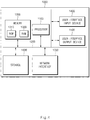
- FIG. 1 is a block diagram illustrating a configuration of a vehicle system including an autonomous controller according to one form of the present disclosure.
- an autonomous controller 100 may be implemented in a vehicle.
- the autonomous controller 100 may be integrally configured with control units in the vehicle or may be implemented as a separate device to be connected with the control units of the vehicle by a separate connection means.
- the vehicle system may include the autonomous controller 100, a sensing device 200, a seat 300, and an authentication device 400.
- the autonomous controller 100 may control autonomous driving and calculate a safety area for determining conversion into an autonomous driving mode based on a current location of the driver's seat.
- the autonomous controller 100 may convert the manual driving mode into the autonomous driving mode when the current location of the driver's seat is located within the safety area, move the current location of the driver's seat into the safety area, and convert the manual driving mode into the autonomous driving mode when the current location of the driver's seat is not located within the safety area.
- the safety area may include information about a sliding location, a reclining angle, and a height of the driver's seat in a state where it is easy for a driver to always keep his or her eyes on the road, manipulate a steering handle, brake, and use other manipulators.
- the autonomous controller 100 which performs the above-mentioned operations, may be implemented in the form of an independent hardware device including a memory and a processor for processing each operation or may be driven in the form of being included in another hardware device such as a microprocessor or a universal computer system.
- the autonomous controller 100 may include a communication device 110, a storage 120, an interface 130, and a processor 140.
- the communication device 110 may be a hardware device implemented with various electronic circuits to transmit and receive a signal through a wireless or wired connection.
- the communication device 110 may perform a network communication technology in the vehicle and may perform vehicle-to-infrastructure (V2I) communication with a server, an infrastructure, or another vehicle outside the vehicle using wireless Internet technology or short range communication technology.
- V2I vehicle-to-infrastructure
- the network communication technology in the vehicle may be to perform inter-vehicle communication through controller area network (CAN) communication, local interconnect network (LIN) communication, flex-ray communication, or the like.
- CAN controller area network
- LIN local interconnect network
- flex-ray communication or the like.
- the wireless Internet technology may include wireless local area network (WLAN), wireless broadband (WiBro), wireless-fidelity (Wi-Fi), world interoperability for microwave access (WiMAX), or the like.
- the short range communication technology may include Bluetooth, ZigBee, ultra wideband (UWB), radio frequency identification (RFID), infrared data association (IrDA), or the like.
- the communication device 110 may perform inter-vehicle communication with the sensing device 200, the seat 300, and the authentication device 400.
- the storage 120 may store a sensing result of the sensing device 200, data obtained by the processor 140, or data, an algorithm, and/or the like necessary for an operation of processor 140.
- the storage 120 may store information about a safety area calculated by the processor 140. Furthermore, the storage 120 may store data and an algorithm for calculating a safety area. Furthermore, the storage 120 may store data for conversion of the autonomous driving mode and the manual driving mode. Furthermore, the storage 120 may store information about a forward obstacle, for example, a forward vehicle, which is detected by the sensing device 200 to control autonomous driving. Furthermore, the storage 120 may store information about a safety area for each driver.
- the storage 120 may include at least one type of storage medium, such as a flash memory type memory, a hard disk type memory, a micro type memory, a card type memory (e.g., a secure digital (SD) card or an extreme digital (XD) card), a random access memory (RAM), a static RAM (SRAM), a read-only memory (ROM), a programmable ROM (PROM), an electrically erasable PROM (EEPROM), a magnetic RAM (MRAM), a magnetic disk, and an optical disk.
- a flash memory type memory e.g., a secure digital (SD) card or an extreme digital (XD) card
- RAM random access memory
- SRAM static RAM
- ROM read-only memory
- PROM programmable ROM
- EEPROM electrically erasable PROM
- MRAM magnetic RAM
- magnetic disk a magnetic disk
- optical disk an optical disk.
- the interface 130 may include an input means for receiving a control command from a user and an output means for outputting an operation state, an operation result, or the like of the autonomous controller 100.
- the input means may include a key button and may further include a mouse, a joystick, a jog shuttle, a stylus pen, or the like. Furthermore, the input means may further include a soft key implemented on a display.
- the output means may include the display and may further include a voice output means such as a speaker.
- a touch sensor such as a touch film, a touch sheet, or a touch pad
- the display operates as a touchscreen and may be implemented in a form where the input means and the output means are integrated with each other.
- the output means may output conversion of the autonomous driving mode and the manual driving mode, an autonomous driving enable state, an autonomous driving disable state, an autonomous driving impossible notification, an autonomous driving possible notification, or the like.
- the output means may be implemented as a cluster, a head up display, an audio, video, navigation (AVN), a display, a warning sound speaker, a haptic device, or the like.
- the display may include at least one of a liquid crystal display (LCD), a thin film transistor-LCD (TFT-LCD), an organic light-emitting diode (OLED) display, a flexible display, a field emission display (FED), or a three-dimensional (3D) display.
- LCD liquid crystal display
- TFT-LCD thin film transistor-LCD
- OLED organic light-emitting diode
- flexible display a field emission display
- FED field emission display
- 3D three-dimensional
- the processor 140 may be electrically connected with the communication device 110, the storage 120, the interface 130, or the like and may electrically control the respective components.
- the processor 140 may be an electrical circuit which executes instructions of software and may perform a variety of data processing and calculation, which will be described below.
- the processor 140 may be, for example, an electronic control unit (ECU), a micro controller unit (MCU), or another sub-controller, which is loaded into the vehicle.
- ECU electronice control unit
- MCU micro controller unit
- the processor 140 may control the overall operation of autonomous driving, may control conversion of the manual driving mode and the autonomous driving mode, or the like.
- the processor 140 may determine whether the driver is in a state for taking over control authority when converting the autonomous driving mode into the manual driving mode and may convert the autonomous driving mode into the manual driving mode.
- the processor 140 may calculate a safety area for determining conversion into the autonomous driving mode based on a current location of the driver's seat and may convert the manual driving mode into the autonomous driving mode when the current location of the driver's seat is located within the safety area, that is, when it is easy for the driver to always keep his or her eyes on the road, manipulate a steering handle, brake, and use other manipulators.
- the processor 140 may convert the manual driving mode into the autonomous driving mode when the current location of the driver's seat is located within the previously calculated safety area and may move the current location of the driver's seat into the safety area and may convert the manual driving mode into the autonomous driving mode when the current location of the driver's seat is not located within the safety area.
- the processor 140 may notify the driver that it is impossible to convert the manual driving mode into the autonomous driving mode by means of the interface 130.
- the processor 140 may determine that there is an external load (an obstacle) when a current value greater than a reference current value occurs, based on a motor current sensor or the like and may determine that it is impossible to move the current location of the driver's seat into the safety area, using the other sensors.
- the processor 140 may notify the driver of a cause of that it is impossible to move the current location of the driver's seat into the safety area by means of the interface 130 and may output a notification of guiding the driver to remove the cause (e.g., an obstacle) of which makes moving the current location of the driver's seat into the safety area impossible by means of the interface 130.
- a cause e.g., an obstacle
- the processor 140 may notify the driver that the manual driving mode is converted into the autonomous driving mode by means of the interface 130.
- the processor 140 may determine safety of the current location of the driver's seat using at least one of a location of the vehicle in the lane, a distance from a forward vehicle, a change in vehicle speed, whether there is rapid deceleration or acceleration, or a face location of the driver and may calculate a safety area based on the current location of the driver's seat.
- the processor 140 may calculate the current location of the driver's seat as the safety area.
- the processor 140 may calculate the current location of the driver's seat as the safety area.
- the processor 140 may calculate the current location of the driver's seat as the safety area.
- the processor 140 may calculate a collision minimum safe distance from a following vehicle using a relative vehicle speed with respect to the following vehicle. When a rate at which the host vehicle violates the collision minimum safe distance during a predetermined time is not greater than a predetermined value, the processor 140 may calculate the current location of the driver's seat as the safety area.
- the processor 140 may calculate the current location of the driver's seat as the safety area.
- the processor 140 may calculate the current location of the driver's seat as the safety area depending on whether rapid deceleration or acceleration occurs during a predetermined time. In this case, the processor 140 may determine rapid acceleration or deceleration using a change value of acceleration of the vehicle. In this case, the rapid acceleration or rapid deceleration may include acceleration of more than a predetermined threshold or deceleration of less than a predetermined threshold.
- the processor 140 may calculate the current location of the driver's seat as the safety area.
- the processor 140 may calculate the current location of the driver's seat as the safety area.
- the processor 140 may calculate the current location of the driver's seat as the safety area. Furthermore, when it is possible to authenticate the driver, the processor 140 may calculate a safety area for each driver and may update the safety area based on a learning algorithm.
- the processor 140 may calculate a safety area using a certain distance and a certain angle with respect to a maximum or minimum movement distance of a seat in a trail and a reclining maximum or minimum angle on design.
- the processor 140 may measure body information of the driver to calculate a safety area of a seat with respect to a criterion.
- the sensing device 200 may include various sensors for measuring the body information of the driver.
- the processor 140 may perform authentication of the driver and when the authentication success, the processor may move the driver's seat using the stored safety area.
- the sensor device 200 may include one or more sensors which detect an obstacle, for example, a forward vehicle, which is located around the vehicle, and measure a distance from the obstacle and/or a relative speed with respect to the obstacle.
- an obstacle for example, a forward vehicle, which is located around the vehicle, and measure a distance from the obstacle and/or a relative speed with respect to the obstacle.
- the sensing device 200 may have a plurality of sensors to sense objects outside the vehicle and may obtain information about a location of the object, a speed of the object, a movement direction of the object, and/or a type (e.g., a vehicle, a pedestrian, a bicycle, a motorcycle, or the like) of the object.
- the sensing device 200 may include an ultrasonic sensor, a radar, a camera, a laser scanner and/or a corner radar, a light detection and ranging (LiDAR), an acceleration sensor, a yaw rate sensor, a torque sensor and/or a wheel speed sensor, a steering angle sensor, or the like.
- LiDAR light detection and ranging
- the authentication device 400 may perform authentication for each driver using a key of the vehicle, a smartphone, iris recognition, face recognition, or the like and may have a means for such authentication.
- the authentication device 400 may be implemented as an authentication means, a driver monitoring system, and the like used upon entrance of the vehicle.
- FIG. 2 is a flowchart illustrating an autonomous control method according to one form of the present disclosure.
- an autonomous controller 100 of FIG. 1 performs a process of FIG. 2 .
- an operation described as being performed by an apparatus may be understood as being controlled by a processor 140 of the autonomous controller 100.
- the apparatus may determine a location of a seat suitable for a driver based on a sliding location, a reclining angle, or a height of the seat, which is determined before manual driving starts after the driver rides in a vehicle.
- the location of the seat suitable for the driver may be a specific value or a specific range.
- the apparatus may determine whether there is a request for conversion into an autonomous driving mode during manual driving. In this case, the apparatus may receive the request for conversion into the autonomous driving mode from the driver by means of an interface 130 of FIG. 1 .
- the apparatus may determine whether a current location of the driver's seat is within a predetermined safety area.
- the safety area may include an area in a sliding distance, a height, or a reclining angle of the driver's seat at which it is possible for the driver to manipulate a steering handle, a brake, and a manipulator switch (e.g., emergency lights or the like).
- a manipulator switch e.g., emergency lights or the like.
- the apparatus may display that the autonomous driving mode starts and may output a notification to the driver.
- the apparatus may move the current location of the driver's seat into the safety area.
- the apparatus may determine whether the moved location of the driver's seat is within the predetermined safety area again. When the current location of the driver's seat is not still within the predetermined safety area, in S106, the apparatus may display that it is impossible to perform autonomous driving and may output a notification to the driver.
- the apparatus may display that the autonomous driving mode starts and may output a notification to the driver.
- the apparatus may convert the manual driving mode into the autonomous driving mode to start to control autonomous driving.
- the apparatus may determine whether the current location of the driver's seat is within the safety area. When the current location of the driver's seat is within the safety area, the apparatus may notify the driver that autonomous driving starts, may convert the manual driving mode into the autonomous driving, and may start autonomous driving.
- the apparatus may move the driver's seat to be located within the safety area. Only when the driver seat is located within the safety area, the apparatus may notify the driver that autonomous driving starts, may convert the manual driving mode into the autonomous driving mode, and may start autonomous driving.
- the apparatus may notify the driver that it is impossible to perform autonomous driving and may fail to convert the manual driving mode into the autonomous driving mode. Furthermore, the apparatus may output a notification message to remove an obstacle for movement of the driver's seat.
- an external factor e.g., an obstacle or the like
- FIG. 3 is a flowchart illustrating a method for calculating a safety area when controlling autonomous driving according to one form of the present disclosure.
- an autonomous controller 100 of FIG. 1 performs a process of FIG. 3 .
- an operation described as being performed by an apparatus may be understood as being controlled by a processor 140 of the autonomous controller 100.
- the apparatus may determine a location of the driver's seat in a vehicle during manual driving. In other words, the apparatus may determine whether steering manipulation and acceleration and deceleration manipulation are suitably performed at a current location of the driver's seat during manual driving to determine the current location of the driver's seat.
- the apparatus may determine safety of the current location of the driver's seat using at least one of a location of the vehicle in the lane, a distance from a forward vehicle, a change in vehicle speed, whether there is rapid deceleration or acceleration, or a face location of the driver and may calculate a safety area based on the current location of the driver's seat meeting the safety.
- the apparatus may calculate the current location of the driver's seat as the safety area.
- the apparatus may calculate the current location of the driver's seat as the safety area.
- the apparatus may determine that the current location of the driver's seat is safe.
- the apparatus may calculate a collision minimum safe distance after a predetermined time (e.g., one second).
- the apparatus may calculate the current location of the driver's seat as the safety area.
- the apparatus may determine that the current location of the driver's seat is safe.
- the apparatus may calculate the current location of the driver's seat as the safety area.
- the apparatus may calculate safety of the current location of the driver's seat depending on whether rapid acceleration or deceleration occurs during a predetermined time. In other words, when rapid acceleration or deceleration does not occur during the predetermined time or when a rapid acceleration or deceleration rate is less than or equal to a predetermined rate, the apparatus may calculate the current location of the driver's seat as the safety area.
- the apparatus may determine safety of the current location of the driver's seat depending on whether an absolute value of acceleration of a host vehicle during a predetermined time is greater than a predetermined value. In other words, when the absolute value of the acceleration of the host vehicle is not greater than the predetermined value, the apparatus may calculate the current location of the driver's seat as the safety area.
- the apparatus may determine the current location of the driver's seat as the safety area. In other words, when a face of the driver is present within a location at which a view of the driver is the least obstructed, the apparatus may determine that the current location of the driver's seat is safe.
- the apparatus may make a margin with respect to the location of the driver's seat meeting the above-mentioned conditions to calculate the safety area.
- the apparatus may continue updating the safety area.
- the margin may be a certain distance from a predetermined seat location or may be calculated by applying a different weight to a predetermined direction.
- the apparatus may include the entire area including all of a plurality of safe locations in the safety area and may include middle points of sporadic locations in the safety area by applying suitable interpolation to the middle points of the sporadic locations.
- the apparatus may use various methods as the method for specifying the range of the safety area and may calculate the safety area using a sensor or the like capable of measuring a body of the driver.
- the apparatus may finally calculate the safety area with regard to a specific range and an error range of a specific angle from a location of each seat based on locations of the seat meeting the above-mentioned conditions for calculating the safety area.
- the apparatus may store information about the calculated safety area in a storage 120 of FIG. 1 .
- the apparatus may store information about a safety area calculated for each driver.
- the driver authentication may be performed by means of an authentication means, a driver monitoring system, and the like used when the driver enters the vehicle.
- the apparatus may continue storing the information about the safety area for each driver.
- the apparatus may store information about each safety area on the basis of the location of the driver's seat.
- the apparatus may store a location of the driver's seat, which is separately stored by the driver, as the safety area. At this time, when there is success in driving authentication, it is possible to store the location of the driver's seat, which is separately stored by the driver, as the safety area.
- the apparatus may calculate and store an area where 95% of adults may manipulate a steering handle and a pedal as the safety area at a maximum or minimum movement distance of a seat in the trail and a reclining maximum or minimum angle on design in an initial state where information about a safety area, authentication information, or the like is not stored.
- the apparatus may recalculate and supplement a safety area based on the current location of the driver's seat.
- the apparatus may authenticate the driver using a specific authentication means (e.g., a key, a smartphone, or the like) of the driver or biometric information (e.g., iris recognition information or face recognition information) of the driver.
- a specific authentication means e.g., a key, a smartphone, or the like
- biometric information e.g., iris recognition information or face recognition information
- the apparatus may correct a location of the driver's seat using the previously stored safety area information.
- the apparatus may move a current location of the driver's seat such that it is easy for the driver to manipulate a steering handle, break, and use the other manipulators in the autonomous driving mode. Because an emergency situation occurs, when suddenly converting the autonomous driving mode into the manual driving mode, the apparatus may safely hand over control authority to the driver.
- FIG. 4 is a block diagram illustrating a computing system according to one form of the present disclosure.
- a computing system 1000 may include at least one processor 1100, a memory 1300, a user interface input device 1400, a user interface output device 1500, storage 1600, and a network interface 1700, which are connected with each other via a bus 1200.
- the processor 1100 may be a central processing unit (CPU) or a semiconductor device that processes instructions stored in the memory 1300 and/or the storage 1600.
- the memory 1300 and the storage 1600 may include various types of volatile or non-volatile storage media.
- the memory 1300 may include a ROM (Read Only Memory) 1310 and a RAM (Random Access Memory) 1320.
- the operations of the method or the algorithm described in connection with various forms disclosed herein may be embodied directly in hardware or a software module executed by the processor 1100, or in a combination thereof.
- the software module may reside on a storage medium (that is, the memory and/or the storage) such as a RAM, a flash memory, a ROM, an EPROM, an EEPROM, a register, a hard disk, a removable disk, and a CD-ROM.
- the exemplary storage medium may be coupled to the processor 1100, and the processor 1100 may read information out of the storage medium and may record information in the storage medium.
- the storage medium may be integrated with the processor 1100.
- the processor and the storage medium may reside in an application specific integrated circuit (ASIC).
- ASIC application specific integrated circuit
- the ASIC may reside within a user terminal.
- the processor and the storage medium may reside in the user terminal as separate components.
- the present technology may calculate a safety area of the driver's seat and may automatically control the driver's seat to be in a state where the driver keeps his or her eyes on the road, when the driver wants to convert a manual driving mode into an autonomous driving mode while driving in the manual driving mode, thus increasing safety of autonomous driving.
Applications Claiming Priority (2)
| Application Number | Priority Date | Filing Date | Title |
|---|---|---|---|
| US202062956654P | 2020-01-03 | 2020-01-03 | |
| KR1020200134500A KR20210088411A (ko) | 2020-01-03 | 2020-10-16 | 자율 주행 제어 장치 및 그 방법 |
Publications (1)
| Publication Number | Publication Date |
|---|---|
| EP3845409A1 true EP3845409A1 (de) | 2021-07-07 |
Family
ID=73654682
Family Applications (1)
| Application Number | Title | Priority Date | Filing Date |
|---|---|---|---|
| EP20210925.2A Withdrawn EP3845409A1 (de) | 2020-01-03 | 2020-12-01 | Autonomer controller und dessen verfahren |
Country Status (3)
| Country | Link |
|---|---|
| US (1) | US20210206393A1 (de) |
| EP (1) | EP3845409A1 (de) |
| CN (1) | CN113071513A (de) |
Citations (4)
| Publication number | Priority date | Publication date | Assignee | Title |
|---|---|---|---|---|
| FR3039123A1 (fr) * | 2015-07-20 | 2017-01-27 | Peugeot Citroen Automobiles Sa | Procede d’aide a l’activation de modes d’assistance a la conduite par reconfiguration de l’habitacle |
| US20170205823A1 (en) * | 2016-01-18 | 2017-07-20 | Ford Global Technologies, Llc | Method and device for operating a motor vehicle |
| US20180272895A1 (en) * | 2015-10-02 | 2018-09-27 | Daimler Ag | Method for Operating a Motor Vehicle and Motor Vehicle |
| US20200001812A1 (en) * | 2019-08-12 | 2020-01-02 | Lg Electronics Inc. | Control method and control device for ivi |
Family Cites Families (6)
| Publication number | Priority date | Publication date | Assignee | Title |
|---|---|---|---|---|
| US9493149B2 (en) * | 2008-07-02 | 2016-11-15 | Michael Phelan | Driver authentication system and method for monitoring and controlling vehicle usage |
| US8874301B1 (en) * | 2013-07-09 | 2014-10-28 | Ford Global Technologies, Llc | Autonomous vehicle with driver presence and physiological monitoring |
| CA3014660C (en) * | 2016-02-15 | 2021-08-17 | Allstate Insurance Company | Early notification of non-autonomous area |
| US10166996B2 (en) * | 2017-02-09 | 2019-01-01 | Toyota Motor Engineering & Manufacturing North America, Inc. | Systems and methods for adaptively communicating notices in a vehicle |
| JP6555597B2 (ja) * | 2017-04-10 | 2019-08-07 | 本田技研工業株式会社 | シート装置 |
| CN108423003A (zh) * | 2018-02-08 | 2018-08-21 | 深圳市芝麻开门电子科技有限公司 | 一种驾驶安全监控方法及系统 |
-
2020
- 2020-12-01 EP EP20210925.2A patent/EP3845409A1/de not_active Withdrawn
- 2020-12-03 US US17/111,103 patent/US20210206393A1/en active Pending
- 2020-12-04 CN CN202011411946.9A patent/CN113071513A/zh active Pending
Patent Citations (4)
| Publication number | Priority date | Publication date | Assignee | Title |
|---|---|---|---|---|
| FR3039123A1 (fr) * | 2015-07-20 | 2017-01-27 | Peugeot Citroen Automobiles Sa | Procede d’aide a l’activation de modes d’assistance a la conduite par reconfiguration de l’habitacle |
| US20180272895A1 (en) * | 2015-10-02 | 2018-09-27 | Daimler Ag | Method for Operating a Motor Vehicle and Motor Vehicle |
| US20170205823A1 (en) * | 2016-01-18 | 2017-07-20 | Ford Global Technologies, Llc | Method and device for operating a motor vehicle |
| US20200001812A1 (en) * | 2019-08-12 | 2020-01-02 | Lg Electronics Inc. | Control method and control device for ivi |
Also Published As
| Publication number | Publication date |
|---|---|
| US20210206393A1 (en) | 2021-07-08 |
| CN113071513A (zh) | 2021-07-06 |
Similar Documents
| Publication | Publication Date | Title |
|---|---|---|
| US10078331B2 (en) | System and method for determining transfer of driving control authority of self-driving vehicle | |
| CN108885836B (zh) | 驾驶辅助装置、系统、方法、控制装置、车辆及介质 | |
| US10163353B2 (en) | Control system and method for determining a safe lane change by vehicles | |
| KR20190130453A (ko) | 차량의 안전 전략 제공 장치 및 방법 | |
| JP5333509B2 (ja) | 先行車追従走行装置 | |
| KR20180109190A (ko) | 딥러닝 기반 자율주행 차량 제어 장치, 그를 포함한 시스템 및 그 방법 | |
| US11827248B2 (en) | Autonomous controller, vehicle system including the same, and method thereof | |
| US11292479B2 (en) | Method and system for assisting a driver in the event of a road departure | |
| EP3893220A1 (de) | Vorrichtung zur steuerung des autonomen fahrens eines fahrzeugs, system damit und verfahren dafür | |
| JP5978709B2 (ja) | 駐車支援装置 | |
| JP2009040267A (ja) | 走行制御装置 | |
| US20230331219A1 (en) | Autonomous driving control system and method thereof | |
| KR20220023528A (ko) | 차량의 군집 주행 제어 장치 및 방법 | |
| KR20210079181A (ko) | 자율 주행 제어 장치, 그를 포함한 차량 시스템 및 그 방법 | |
| US20190329765A1 (en) | Vehicle control device and vehicle control method | |
| JP5821532B2 (ja) | 車両用走行制御装置 | |
| CN114572199A (zh) | 用于控制车辆的装置和方法 | |
| EP3845409A1 (de) | Autonomer controller und dessen verfahren | |
| US20220161805A1 (en) | Vehicle controller and method thereof | |
| JP2009255629A (ja) | 車両の接触回避支援装置 | |
| US20220315001A1 (en) | Driving assistance device, driving assistance method, and storage medium | |
| CN116867697A (zh) | 辅助驾驶系统对交通事件的物理反馈确认 | |
| KR20210088411A (ko) | 자율 주행 제어 장치 및 그 방법 | |
| JP6882400B2 (ja) | 自動運転制御装置および自動運転制御方法 | |
| KR20210063893A (ko) | 차로 변경 보조 장치, 그를 포함한 시스템 및 그 방법 |
Legal Events
| Date | Code | Title | Description |
|---|---|---|---|
| PUAI | Public reference made under article 153(3) epc to a published international application that has entered the european phase |
Free format text: ORIGINAL CODE: 0009012 |
|
| STAA | Information on the status of an ep patent application or granted ep patent |
Free format text: STATUS: THE APPLICATION HAS BEEN PUBLISHED |
|
| AK | Designated contracting states |
Kind code of ref document: A1 Designated state(s): AL AT BE BG CH CY CZ DE DK EE ES FI FR GB GR HR HU IE IS IT LI LT LU LV MC MK MT NL NO PL PT RO RS SE SI SK SM TR |
|
| RAP3 | Party data changed (applicant data changed or rights of an application transferred) |
Owner name: HYUNDAI MOTOR COMPANY Owner name: KIA CORPORATION |
|
| STAA | Information on the status of an ep patent application or granted ep patent |
Free format text: STATUS: REQUEST FOR EXAMINATION WAS MADE |
|
| 17P | Request for examination filed |
Effective date: 20211227 |
|
| RBV | Designated contracting states (corrected) |
Designated state(s): AL AT BE BG CH CY CZ DE DK EE ES FI FR GB GR HR HU IE IS IT LI LT LU LV MC MK MT NL NO PL PT RO RS SE SI SK SM TR |
|
| STAA | Information on the status of an ep patent application or granted ep patent |
Free format text: STATUS: EXAMINATION IS IN PROGRESS |
|
| 17Q | First examination report despatched |
Effective date: 20230306 |
|
| P01 | Opt-out of the competence of the unified patent court (upc) registered |
Effective date: 20230508 |
|
| STAA | Information on the status of an ep patent application or granted ep patent |
Free format text: STATUS: THE APPLICATION HAS BEEN WITHDRAWN |
|
| 18W | Application withdrawn |
Effective date: 20230630 |