EP3844744B1 - Systeme und verfahren zur rauschunterdrückung mittels mikrofonprojektion - Google Patents
Systeme und verfahren zur rauschunterdrückung mittels mikrofonprojektion Download PDFInfo
- Publication number
- EP3844744B1 EP3844744B1 EP19769939.0A EP19769939A EP3844744B1 EP 3844744 B1 EP3844744 B1 EP 3844744B1 EP 19769939 A EP19769939 A EP 19769939A EP 3844744 B1 EP3844744 B1 EP 3844744B1
- Authority
- EP
- European Patent Office
- Prior art keywords
- filter
- noise
- location
- signal
- cancellation
- Prior art date
- Legal status (The legal status is an assumption and is not a legal conclusion. Google has not performed a legal analysis and makes no representation as to the accuracy of the status listed.)
- Active
Links
Images


Classifications
-
- G—PHYSICS
- G10—MUSICAL INSTRUMENTS; ACOUSTICS
- G10K—SOUND-PRODUCING DEVICES; METHODS OR DEVICES FOR PROTECTING AGAINST, OR FOR DAMPING, NOISE OR OTHER ACOUSTIC WAVES IN GENERAL; ACOUSTICS NOT OTHERWISE PROVIDED FOR
- G10K11/00—Methods or devices for transmitting, conducting or directing sound in general; Methods or devices for protecting against, or for damping, noise or other acoustic waves in general
- G10K11/16—Methods or devices for protecting against, or for damping, noise or other acoustic waves in general
- G10K11/175—Methods or devices for protecting against, or for damping, noise or other acoustic waves in general using interference effects; Masking sound
- G10K11/178—Methods or devices for protecting against, or for damping, noise or other acoustic waves in general using interference effects; Masking sound by electro-acoustically regenerating the original acoustic waves in anti-phase
- G10K11/1785—Methods, e.g. algorithms; Devices
- G10K11/17853—Methods, e.g. algorithms; Devices of the filter
-
- G—PHYSICS
- G10—MUSICAL INSTRUMENTS; ACOUSTICS
- G10K—SOUND-PRODUCING DEVICES; METHODS OR DEVICES FOR PROTECTING AGAINST, OR FOR DAMPING, NOISE OR OTHER ACOUSTIC WAVES IN GENERAL; ACOUSTICS NOT OTHERWISE PROVIDED FOR
- G10K11/00—Methods or devices for transmitting, conducting or directing sound in general; Methods or devices for protecting against, or for damping, noise or other acoustic waves in general
- G10K11/16—Methods or devices for protecting against, or for damping, noise or other acoustic waves in general
- G10K11/175—Methods or devices for protecting against, or for damping, noise or other acoustic waves in general using interference effects; Masking sound
- G10K11/178—Methods or devices for protecting against, or for damping, noise or other acoustic waves in general using interference effects; Masking sound by electro-acoustically regenerating the original acoustic waves in anti-phase
- G10K11/1787—General system configurations
-
- G—PHYSICS
- G10—MUSICAL INSTRUMENTS; ACOUSTICS
- G10K—SOUND-PRODUCING DEVICES; METHODS OR DEVICES FOR PROTECTING AGAINST, OR FOR DAMPING, NOISE OR OTHER ACOUSTIC WAVES IN GENERAL; ACOUSTICS NOT OTHERWISE PROVIDED FOR
- G10K11/00—Methods or devices for transmitting, conducting or directing sound in general; Methods or devices for protecting against, or for damping, noise or other acoustic waves in general
- G10K11/16—Methods or devices for protecting against, or for damping, noise or other acoustic waves in general
- G10K11/175—Methods or devices for protecting against, or for damping, noise or other acoustic waves in general using interference effects; Masking sound
- G10K11/178—Methods or devices for protecting against, or for damping, noise or other acoustic waves in general using interference effects; Masking sound by electro-acoustically regenerating the original acoustic waves in anti-phase
- G10K11/1781—Methods or devices for protecting against, or for damping, noise or other acoustic waves in general using interference effects; Masking sound by electro-acoustically regenerating the original acoustic waves in anti-phase characterised by the analysis of input or output signals, e.g. frequency range, modes, transfer functions
- G10K11/17813—Methods or devices for protecting against, or for damping, noise or other acoustic waves in general using interference effects; Masking sound by electro-acoustically regenerating the original acoustic waves in anti-phase characterised by the analysis of input or output signals, e.g. frequency range, modes, transfer functions characterised by the analysis of the acoustic paths, e.g. estimating, calibrating or testing of transfer functions or cross-terms
-
- G—PHYSICS
- G10—MUSICAL INSTRUMENTS; ACOUSTICS
- G10K—SOUND-PRODUCING DEVICES; METHODS OR DEVICES FOR PROTECTING AGAINST, OR FOR DAMPING, NOISE OR OTHER ACOUSTIC WAVES IN GENERAL; ACOUSTICS NOT OTHERWISE PROVIDED FOR
- G10K11/00—Methods or devices for transmitting, conducting or directing sound in general; Methods or devices for protecting against, or for damping, noise or other acoustic waves in general
- G10K11/16—Methods or devices for protecting against, or for damping, noise or other acoustic waves in general
- G10K11/175—Methods or devices for protecting against, or for damping, noise or other acoustic waves in general using interference effects; Masking sound
- G10K11/178—Methods or devices for protecting against, or for damping, noise or other acoustic waves in general using interference effects; Masking sound by electro-acoustically regenerating the original acoustic waves in anti-phase
- G10K11/1781—Methods or devices for protecting against, or for damping, noise or other acoustic waves in general using interference effects; Masking sound by electro-acoustically regenerating the original acoustic waves in anti-phase characterised by the analysis of input or output signals, e.g. frequency range, modes, transfer functions
- G10K11/17821—Methods or devices for protecting against, or for damping, noise or other acoustic waves in general using interference effects; Masking sound by electro-acoustically regenerating the original acoustic waves in anti-phase characterised by the analysis of input or output signals, e.g. frequency range, modes, transfer functions characterised by the analysis of the input signals only
- G10K11/17823—Reference signals, e.g. ambient acoustic environment
-
- G—PHYSICS
- G10—MUSICAL INSTRUMENTS; ACOUSTICS
- G10K—SOUND-PRODUCING DEVICES; METHODS OR DEVICES FOR PROTECTING AGAINST, OR FOR DAMPING, NOISE OR OTHER ACOUSTIC WAVES IN GENERAL; ACOUSTICS NOT OTHERWISE PROVIDED FOR
- G10K11/00—Methods or devices for transmitting, conducting or directing sound in general; Methods or devices for protecting against, or for damping, noise or other acoustic waves in general
- G10K11/16—Methods or devices for protecting against, or for damping, noise or other acoustic waves in general
- G10K11/175—Methods or devices for protecting against, or for damping, noise or other acoustic waves in general using interference effects; Masking sound
- G10K11/178—Methods or devices for protecting against, or for damping, noise or other acoustic waves in general using interference effects; Masking sound by electro-acoustically regenerating the original acoustic waves in anti-phase
- G10K11/1781—Methods or devices for protecting against, or for damping, noise or other acoustic waves in general using interference effects; Masking sound by electro-acoustically regenerating the original acoustic waves in anti-phase characterised by the analysis of input or output signals, e.g. frequency range, modes, transfer functions
- G10K11/17821—Methods or devices for protecting against, or for damping, noise or other acoustic waves in general using interference effects; Masking sound by electro-acoustically regenerating the original acoustic waves in anti-phase characterised by the analysis of input or output signals, e.g. frequency range, modes, transfer functions characterised by the analysis of the input signals only
- G10K11/17825—Error signals
-
- G—PHYSICS
- G10—MUSICAL INSTRUMENTS; ACOUSTICS
- G10K—SOUND-PRODUCING DEVICES; METHODS OR DEVICES FOR PROTECTING AGAINST, OR FOR DAMPING, NOISE OR OTHER ACOUSTIC WAVES IN GENERAL; ACOUSTICS NOT OTHERWISE PROVIDED FOR
- G10K11/00—Methods or devices for transmitting, conducting or directing sound in general; Methods or devices for protecting against, or for damping, noise or other acoustic waves in general
- G10K11/16—Methods or devices for protecting against, or for damping, noise or other acoustic waves in general
- G10K11/175—Methods or devices for protecting against, or for damping, noise or other acoustic waves in general using interference effects; Masking sound
- G10K11/178—Methods or devices for protecting against, or for damping, noise or other acoustic waves in general using interference effects; Masking sound by electro-acoustically regenerating the original acoustic waves in anti-phase
- G10K11/1787—General system configurations
- G10K11/17879—General system configurations using both a reference signal and an error signal
- G10K11/17881—General system configurations using both a reference signal and an error signal the reference signal being an acoustic signal, e.g. recorded with a microphone
-
- G—PHYSICS
- G10—MUSICAL INSTRUMENTS; ACOUSTICS
- G10K—SOUND-PRODUCING DEVICES; METHODS OR DEVICES FOR PROTECTING AGAINST, OR FOR DAMPING, NOISE OR OTHER ACOUSTIC WAVES IN GENERAL; ACOUSTICS NOT OTHERWISE PROVIDED FOR
- G10K2210/00—Details of active noise control [ANC] covered by G10K11/178 but not provided for in any of its subgroups
- G10K2210/10—Applications
- G10K2210/108—Communication systems, e.g. where useful sound is kept and noise is cancelled
- G10K2210/1082—Microphones, e.g. systems using "virtual" microphones
-
- G—PHYSICS
- G10—MUSICAL INSTRUMENTS; ACOUSTICS
- G10K—SOUND-PRODUCING DEVICES; METHODS OR DEVICES FOR PROTECTING AGAINST, OR FOR DAMPING, NOISE OR OTHER ACOUSTIC WAVES IN GENERAL; ACOUSTICS NOT OTHERWISE PROVIDED FOR
- G10K2210/00—Details of active noise control [ANC] covered by G10K11/178 but not provided for in any of its subgroups
- G10K2210/10—Applications
- G10K2210/128—Vehicles
- G10K2210/1282—Automobiles
-
- G—PHYSICS
- G10—MUSICAL INSTRUMENTS; ACOUSTICS
- G10K—SOUND-PRODUCING DEVICES; METHODS OR DEVICES FOR PROTECTING AGAINST, OR FOR DAMPING, NOISE OR OTHER ACOUSTIC WAVES IN GENERAL; ACOUSTICS NOT OTHERWISE PROVIDED FOR
- G10K2210/00—Details of active noise control [ANC] covered by G10K11/178 but not provided for in any of its subgroups
- G10K2210/30—Means
- G10K2210/301—Computational
- G10K2210/3011—Single acoustic input
-
- G—PHYSICS
- G10—MUSICAL INSTRUMENTS; ACOUSTICS
- G10K—SOUND-PRODUCING DEVICES; METHODS OR DEVICES FOR PROTECTING AGAINST, OR FOR DAMPING, NOISE OR OTHER ACOUSTIC WAVES IN GENERAL; ACOUSTICS NOT OTHERWISE PROVIDED FOR
- G10K2210/00—Details of active noise control [ANC] covered by G10K11/178 but not provided for in any of its subgroups
- G10K2210/30—Means
- G10K2210/301—Computational
- G10K2210/3026—Feedback
-
- G—PHYSICS
- G10—MUSICAL INSTRUMENTS; ACOUSTICS
- G10K—SOUND-PRODUCING DEVICES; METHODS OR DEVICES FOR PROTECTING AGAINST, OR FOR DAMPING, NOISE OR OTHER ACOUSTIC WAVES IN GENERAL; ACOUSTICS NOT OTHERWISE PROVIDED FOR
- G10K2210/00—Details of active noise control [ANC] covered by G10K11/178 but not provided for in any of its subgroups
- G10K2210/30—Means
- G10K2210/301—Computational
- G10K2210/3027—Feedforward
-
- G—PHYSICS
- G10—MUSICAL INSTRUMENTS; ACOUSTICS
- G10K—SOUND-PRODUCING DEVICES; METHODS OR DEVICES FOR PROTECTING AGAINST, OR FOR DAMPING, NOISE OR OTHER ACOUSTIC WAVES IN GENERAL; ACOUSTICS NOT OTHERWISE PROVIDED FOR
- G10K2210/00—Details of active noise control [ANC] covered by G10K11/178 but not provided for in any of its subgroups
- G10K2210/30—Means
- G10K2210/301—Computational
- G10K2210/3028—Filtering, e.g. Kalman filters or special analogue or digital filters
-
- G—PHYSICS
- G10—MUSICAL INSTRUMENTS; ACOUSTICS
- G10K—SOUND-PRODUCING DEVICES; METHODS OR DEVICES FOR PROTECTING AGAINST, OR FOR DAMPING, NOISE OR OTHER ACOUSTIC WAVES IN GENERAL; ACOUSTICS NOT OTHERWISE PROVIDED FOR
- G10K2210/00—Details of active noise control [ANC] covered by G10K11/178 but not provided for in any of its subgroups
- G10K2210/30—Means
- G10K2210/301—Computational
- G10K2210/3055—Transfer function of the acoustic system
-
- G—PHYSICS
- G10—MUSICAL INSTRUMENTS; ACOUSTICS
- G10K—SOUND-PRODUCING DEVICES; METHODS OR DEVICES FOR PROTECTING AGAINST, OR FOR DAMPING, NOISE OR OTHER ACOUSTIC WAVES IN GENERAL; ACOUSTICS NOT OTHERWISE PROVIDED FOR
- G10K2210/00—Details of active noise control [ANC] covered by G10K11/178 but not provided for in any of its subgroups
- G10K2210/30—Means
- G10K2210/321—Physical
- G10K2210/3221—Headrests, seats or the like, for personal ANC systems
Definitions
- a noise-cancellation system includes a noise-cancellation filter configured to generate a noise-cancellation signal based on a noise signal received from a noise sensor; an actuator disposed at a first location within a predefined volume and configured to receive the noise-cancellation signal and to transduce a noise-cancellation audio signal within the predefined volume; a reference sensor disposed at a second location within the predefined volume and to output a reference sensor signal, the reference sensor signal being representative of an undesired noise at the second location; a filter configured to filter the noise-cancellation signal and the reference sensor signal to output a filter output signal, the filter output signal representing an estimate of the undesired nose at a third location remote from the first location and the second location; and an adjustment module configured to adjust the noise-cancellation filter, based on the filter output signal, such that the noise-cancellation audio signal destructively interferes with the undesired noise at the third location.
- the filter output signal is based on an estimate of a relationship between the first location and the third location and based on an estimate of a relationship between the second location and the third location.
- the filter comprises a first filter configured to estimate a relationship between the second location and the third location, the first filter being configured to receive and filter the reference sensor signal and to output a first filter output signal, the first filter output signal being an estimate of the undesired noise at the third location.
- the filter further comprises a second filter configured to estimate a relationship between the first location and the third location, the second filter being configured to receive
- the filter comprises at least one predictive filter such that the estimate the undesired noise at the third location is an estimate of the undesired noise at the third location at a future point in time.
- the at least one predictive filter is a Wiener filter.
- program code stored on a non-transitory storage medium that, when executed by a processor, includes the steps of: generating, with a noise-cancellation filter, a noise-cancellation signal based on a noise signal received from a noise sensor; providing the noise-cancellation signal to an actuator disposed at a first location for transduction of a noise-cancellation audio signal within the predefined volume; receiving a reference sensor signal from a reference sensor disposed at a second location within the predefined volume, the reference sensor signal being representative of an undesired noise at the second location; filtering, with a filter, the noise-cancellation signal and the reference sensor signal to output a filter output signal, the filter output signal representing an estimate of the undesired noise at a third location remote from the first location and the second location; and adjusting the noise-cancellation filter, based on the filter output, such that the noise-cancellation audio signal destructively interferes with the undesired noise at the third location.
- the filter output signal is based on an estimate of a relationship between the first location and the third location and based on an estimate of a relationship between the second location and the third location.
- the filter includes a first filter configured to estimate a relationship between the second location and the third location, the first filter being configured to receive and filter the reference sensor signal and to output a first filter output signal, the first filter output signal being an estimate of the undesired noise at the third location.
- the filter further includes a second filter configured to estimate a relationship between the first location and the third location, the second filter being configured to receive and filter the noise-cancellation signal and to output a second filter output signal, the second filter output signal being an estimate of the noise-cancellation audio signal at the third location, wherein the second
- filter output signal is configured to cancel a portion of the first filter output signal based on the noise-cancellation audio signal received at the reference sensor, when the first filter output signal and the second filter output signal are summed.
- the filter includes at least one predictive filter such that the estimate the undesired noise at the third location is an estimate of the undesired noise at the third location at a future point in time.
- the at least one predictive filter is a Wiener filter.
- a noise-cancellation method comprises the steps of: generating, with a noise-cancellation filter, a noise-cancellation signal based on a noise signal received from a noise sensor; providing the noise-cancellation signal to an actuator disposed at a first location for transduction of a noise-cancellation audio signal within the predefined volume; receiving a reference sensor signal from a reference sensor disposed at a second location within the predefined volume, the reference sensor signal being representative of an undesired noise at the second location; filtering, with a filter, the noise-cancellation signal and the reference sensor signal to output a filter output signal, the filter output signal representing an estimate of the undesired noise at a third location remote from the first location and the second location; and adjusting the noise-cancellation filter, based on the filter output, such that the noise-cancellation audio signal destructively interferes with the undesired noise at the third location.
- the filter output signal is based on an estimate of a relationship between the first location and the third location and based on an estimate of a relationship between the second location and the third location.
- the filter comprises a first filter configured to estimate a relationship between the second location and the third location, the first filter being configured to receive and filter the reference sensor signal and to output a first filter output signal, the first filter output signal being an estimate of the undesired noise at the third location.
- the filter further comprises a second filter configured to estimate a relationship between the first location and the third location, the second filter being configured to receive and filter the noise-cancellation signal and to output a second filter output signal, the second filter output signal being an estimate of the noise-cancellation audio signal at the third location, wherein the second filter output signal is configured to cancel a portion of the first filter output signal based on the noise-cancellation audio signal received at the reference sensor, when the first filter output signal and the second filter output signal are summed.
- the filter includes at least one predictive filter such that the estimate the undesired noise at the third location is an estimate of the undesired noise at the third location at a future point in time.
- the reference sensor may be placed in the roof, pillar, or headrest, but the noise should be canceled at the passenger's ears.
- the error signal is indicative of the error at the reference sensor, but not at the passenger's ears.
- This is undesirable because the objective of a road-noise-cancellation system is to cancel noise at the passenger's ears.
- placing microphones on passenger's ears is impractical-even though the ear mic signal is typically required for the adaptive algorithm to function optimally.
- Various embodiments disclosed herein are directed to a noise-cancellation system that estimates or predicts an error signal representative of residual uncancelled noise at a location remote from the reference sensor.
- the estimation or prediction in an embodiment, is based on available information from, namely, remote reference microphones, and from knowledge of the relationship between those remote microphones and the noise field at the passenger's ears and of the output of the noise cancellation system itself. Predicting a future value of the noise is possible because future samples are correlated with current samples, and so knowledge of the current state has information about the future state.
- the resulting adjustment to the adaptive filter will minimize the estimated or predicted error signal and thus cancel the undesired noise at remote location rather than at the reference sensor, effectively projecting the reference sensor at the remote location. This may alternately be understood as shifting the cancellation zone from the reference sensor to the location remote from the reference sensor.
- noise sensor 106 is configured to generate noise signal(s) 114 representative of the undesired sound, or a source of the undesired sound, within predefined volume 104.
- noise sensor 106 may be an accelerometer mounted to and configured to detect vibrations transmitted through a vehicle structure 116. Vibrations transmitted through the vehicle structure 116 are transduced by the structure into undesired sound in the vehicle cabin (perceived as a road noise), thus an accelerometer mounted to the structure provides a signal representative of the undesired sound.
- Actuator 110 may, for example, be speakers distributed in discrete locations about the perimeter of the predefined volume 104.
- four or more speakers may be disposed within a vehicle cabin, each of the four speakers being located within a respective door of the vehicle and configured project sound into the vehicle cabin.
- speakers may be located within a headrest, or elsewhere in the vehicle cabin.
- a noise-cancellation signal 118 may be generated by controller 112 and provided to one or more speakers in the predefined volume, which transduce the noise-cancellation signal 118 to acoustic energy (i.e., sound waves).
- the acoustic energy produced as a result of noise-cancellation signal 118 is approximately 180° out of phase with-and thus destructively interferes with-the undesired sound within the cancellation zone 102.
- the combination of sound waves generated from the noise-cancellation signal 118 and the undesired noise in the predefined volume results in cancellation of the undesired noise, as perceived by a listener in a cancellation zone.
- Reference sensor 108 disposed within the predefined volume, generates a reference sensor signal 120 based on detection of residual noise resulting from the combination of the sound waves generated from the noise-cancellation signal 118 and the undesired sound in the predefined volume.
- the reference sensor signal 120 is provided to controller 112 as feedback. Because reference sensor signal 120 will represent residual noise, uncancelled by the noise-cancellation signal, reference sensor signal 120 may be understood as an error signal.
- Reference sensors 108 may be, for example, at least one microphone mounted within a vehicle cabin (e.g., in the roof, headrests, pillars, or elsewhere within the cabin).
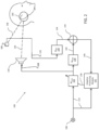
- Adaptive processing module 132 receives as inputs the reference sensor signal 134 (filtered by Wref filter 130 and summed with the output of Wcmd filter 128, as will be described below) and the noise signal 114 and, using those inputs, generates a filter update signal 136.
- the filter update signal 136 is an update to the filter coefficients implemented in Wadapt filter 126.
- the noise-cancellation signal 118 produced by the updated Wadapt filter 126 will minimize error signal 146.
- Wref filter 130 is thus configured to compute a statistical estimate of the residual noise at the passenger's ears using the reference sensor signal 120 as an input and filter that signal to produce the estimate or prediction as an output (i.e., Wref output signal 134).
- the Wref output signal 134 will thus represent an estimate or prediction of the noise at the passenger's ear, based on the input reference sensor signal 120 and the estimated/predicted relationship between the location of the reference sensor 108 and the cancellation zone 102.
- the output of Wref filter 130 is the statistical estimate or prediction of only the residual noise at the passenger's ears, as described above; however, in practice, reference sensors 108 likely also receive the noise-cancellation audio signal as output by actuator 110, as they are positioned within the same predefined volume 104.
- Wcmd filter 128 is configured to estimate or predict the relationship (e.g., the transfer function) between the location of the actuator 110 (i.e., the origin of the noise-cancellation audio signal) and the cancellation zone 102, which will be determined by the physical path 140 between the locations of each.
- the relationship between the actuator 110 and the cancellation zone 102 will likely be dominated by the acoustic modes of the predefined volume (e.g., the vehicle cabin) and will not vary greatly with time.
- the reference sensor 108 will likely pick up the noise-cancellation audio signal output from the actuator 110.
- the Wcmd filter 128 may be configured to correct for this, such that the correct estimate or prediction is obtained in the presence of both the cancellation signal along with the undesired noise.
- Wcmd filter 128 is thus configured to compute a statistical estimate of the noise-cancellation audio signal 118 at the cancellation zone and configured to remove the noise-cancellation signal audio signal picked up by reference sensor 108.
- the Wmcd output signal 142 will thus represent estimate or prediction of the noise-cancellation audio signal 118 at the cancellation zone and will be configured to cancel the noise-cancellation signal audio signal picked up by reference sensor 108.
- the result is an estimate (possibly at a future time, e.g., predictive) of the noise at the passenger's ears that is due to both the road induced noise and the cancellation signal.
- Wref and Wcmd are designed to estimate or predict the sound at the occupant's ears using as inputs the reference microphones and the noise-cancellation signals.
- Wiener filters that optimize the mean-square error can be used, as can other filter design techniques that optimize other criterion (weighted mean-square error, L1-norm, H-infinity norm, etc.).
- the Wref filter 130 and Wcmd filter 128 may be defined in accordance with the equations described below.
- the noise-cancellation signal and the reference sensor signal are filtered to output a filter output signal, the filter output signal representing an estimate or prediction of the undesired noise at a third location remote from the first location and the second location.
- the filter output signal is based on an estimate or prediction of a relationship between the first location and the third location and based on an estimate or prediction of a relationship between the second location and the third location.
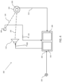
- Controller 304 may be controller 112 or may be implemented as a separate controller. In various embodiments, controller 304 may be implemented by a general process computer, an FPGA, an ASIC, or any other controller suitable for executing the steps described in connection with FIGs. 5-6 .
- FIGs 5 and 6 generally show alternate approaches for collecting data and generating filters Wcmd filter 128 and Wref filter 130 and in order to minimize the cost function of equation (9) stated above.
- FIG. 5 there is shown a first method 400 for collecting data and generating filters Wcmd filter 128 and Wref filter 130.
- a representative undesired noise may be generated within the predefined volume 104. This may be accomplished, in the vehicle embodiment, by driving the vehicle down a road.
- a command signal 312 may be injected into actuator 110.
- the command signal 312 is a computer generated random signal that is statistically independent of the road noise signal. This random signal may be spectrally shaped so that its energy is at a comparable level to the road noise on a frequency-by-frequency basis.
- a noise-shaping filter (that is road and speed dependent) may be implemented by processor 308 and applied to the command signal 312. The noise-shaping filter may be configured to drive the actuator 110 at a level that does not overdrive the representative undesired noise.
- step 406 which occurs concurrently with step 402 and 404, the audio signal resulting from the representative undesired noise and the output audio signal from actuator 110 will be detected by reference sensor 108 and error sensor 302.
- the resulting output signals from each, reference sensor signal 120 and error sensor signal 310, may be recorded, e.g., in non-transitory storage medium 306.
- the injected command signal 312, and the recorded reference sensor signal 120 and error sensor signal 310 may be used to generate filters Wcmd filter 128 and Wref filter 130 in order to minimize the cost function of equation (9) stated above.
- Generating Wcmd filter 128 and Wref filter 130 may be accomplished by standard solution techniques as are known in the art.
- FIG. 6 shows, in an alternate embodiment, method 500, which may be accomplished by injecting a command signal 312 to actuator 110 non-concurrently as opposed to concurrently as described in steps 402, 404, and 406. Separating the road noise data collection and the command signal data collection avoids the iterative process of method 400.
- a representative undesired noise may be generated within the predefined volume 104. This may be accomplished, in the vehicle embodiment, by driving the vehicle down a road.
- step 504 which occurs concurrently with step 502, the representative undesired noise will be detected by reference sensor 108 and error sensor 302, and the resulting output signals from each, reference sensor signal 120 and error sensor signal 310, may be recorded, e.g., in non-transitory storage medium 306.
- command signal 312 may be generated and injected to actuator 110.
- Communication signal 312 may be any command signal suitable for generating T de [ n ] and T dr [ n ], as described below.
- step 506 preferably occurs with any other undesired noises minimized.
- step 506 may be performed in a quiet space (such as a quiet garage), without the vehicle engine running.
- step 508 which occurs concurrently with step 506, the audio signal generated by actuator 110, in response to the input command signal, will be detected by reference sensor 108 and error sensor 302.
- the resulting output signals from each, reference sensor signal 120 and error sensor signal 310, may be recorded, e.g., in non-transitory storage medium 306.
- methods 400 and 500 may be repeated or otherwise performed for any number of speakers, error sensors, or reference sensors.
- the functionality described herein, or portions thereof, and its various modifications can be implemented, at least in part, via a computer program product, e.g., a computer program tangibly embodied in an information carrier, such as one or more non-transitory machine-readable media or storage device, for execution by, or to control the operation of, one or more data processing apparatus, e.g., a programmable processor, a computer, multiple computers, and/or programmable logic components.
- a computer program product e.g., a computer program tangibly embodied in an information carrier, such as one or more non-transitory machine-readable media or storage device, for execution by, or to control the operation of, one or more data processing apparatus, e.g., a programmable processor, a computer, multiple computers, and/or programmable logic components.
- a computer program can be written in any form of programming language, including compiled or interpreted languages, and it can be deployed in any form, including as a stand-alone program or as a module, component, subroutine, or other unit suitable for use in a computing environment.
- a computer program can be deployed to be executed on one computer or on multiple computers at one site or distributed across multiple sites and interconnected by a network.
- Actions associated with implementing all or part of the functions can be performed by one or more programmable processors executing one or more computer programs to perform the functions of the calibration process. All or part of the functions can be implemented as, special purpose logic circuitry, e.g., an FPGA and/or an ASIC (applicationspecific integrated circuit).
- special purpose logic circuitry e.g., an FPGA and/or an ASIC (applicationspecific integrated circuit).
Landscapes
- Physics & Mathematics (AREA)
- Engineering & Computer Science (AREA)
- Acoustics & Sound (AREA)
- Multimedia (AREA)
- Soundproofing, Sound Blocking, And Sound Damping (AREA)
- Fittings On The Vehicle Exterior For Carrying Loads, And Devices For Holding Or Mounting Articles (AREA)
- Circuit For Audible Band Transducer (AREA)
Claims (14)
- Rauschunterdrückungssystem (100), umfassend:ein Rauschunterdrückungsfilter (126), das konfiguriert ist, um ein Rauschunterdrückungssignal (118) basierend auf einem von einem Rauschsensor (106) empfangenen Rauschsignal (114) zu erzeugen (202);einen Stellantrieb (110), der an einer ersten Stelle innerhalb eines vordefinierten Volumens (104) angeordnet und konfiguriert ist, um das Rauschunterdrückungssignal (118) zu empfangen, und um ein Rauschunterdrückungsaudiosignal innerhalb des vordefinierten Volumens (104) umzuwandeln;einen Referenzsensor (108), der an einer zweiten Stelle innerhalb des vordefinierten Volumens (104) angeordnet ist, und um ein Referenzsensorsignal (120) auszugeben, wobei das Referenzsensorsignal (120) repräsentativ für ein unerwünschtes Rauschen an der zweiten Stelle ist;ein Filter, das konfiguriert ist, um das Rauschunterdrückungssignal (118) und das Referenzsensorsignal (120) zu filtern (208), um ein Filterausgangssignal (146) auszugeben, wobei das Filterausgangssignal (146) eine Schätzung des unerwünschten Rauschens an einer dritten Stelle (102) darstellt, die von der ersten Stelle und der zweiten Stelle entfernt ist; undein Anpassungsmodul (132), das konfiguriert ist, um das Rauschunterdrückungsfilter (126) basierend auf dem Filterausgangssignal (146) anzupassen (210), sodass das Rauschunterdrückungsaudiosignal das unerwünschte Rauschen an der dritten Stelle (102) zerstörend stört,wobei das Filter ein erstes Filter (130) umfasst, das konfiguriert ist, um eine Beziehung zwischen der zweiten Stelle und der dritten Stelle (102) zu schätzen, wobei das erste Filter (130) konfiguriert ist, um das Referenzsensorsignal (120) zu empfangen und zu filtern, und um ein erstes Filterausgangssignal (134) auszugeben, wobei das erste Filterausgangssignal (134) eine Schätzung des unerwünschten Rauschens an der dritten Stelle (102) ist, undwobei das Filter weiter ein zweites Filter (128) umfasst, das konfiguriert ist, um eine Beziehung zwischen der ersten Stelle und der dritten Stelle (102) zu schätzen, wobei das zweite Filter (128) konfiguriert ist, um das Rauschunterdrückungssignal (118) zu empfangen und zu filtern und um ein zweites Filterausgangssignal (142) auszugeben, wobei das zweite Filterausgangssignal (142) eine Schätzung des Rauschunterdrückungsaudiosignals an der dritten Stelle (102) ist,dadurch gekennzeichnet, dassdas zweite Filterausgangssignal (142) konfiguriert ist, um einen Abschnitt des ersten Filterausgangssignals (134) basierend auf dem am Referenzsensor (108) empfangenen Rauschunterdrückungsaudiosignal aufzuheben, wenn das erste Filterausgangssignal (134) und das zweite Filterausgangssignal (142) summiert (144) werden,und dadurch, dassdas zweite Filter (128) weiter konfiguriert ist, um das vom Referenzsensor (108) empfangene Rauschunterdrückungsaudiosignal zu korrigieren.
- Rauschunterdrückungssystem (100) nach Anspruch 1, wobei das Filterausgangssignal (146) auf einer Schätzung einer Beziehung zwischen der ersten Stelle und der dritten Stelle (102) basiert, und auf einer Schätzung einer Beziehung zwischen der zweiten Stelle und der dritten Stelle (102) basiert.
- Rauschunterdrückungssystem (100) nach Anspruch 1, wobei das Filter mindestens ein prädiktives Filter umfasst, sodass die Schätzung des unerwünschten Rauschens an der dritten Stelle (102) eine Schätzung des unerwünschten Rauschens an der dritten Stelle (102) zu einem zukünftigen Zeitpunkt ist.
- Rauschunterdrückungssystem nach Anspruch 3, wobei das mindestens eine prädiktive Filter ein Wiener-Filter ist.
- Programmcode, der auf einem nichtflüchtigen Speichermedium gespeichert ist, der, wenn er durch einen Prozessor ausgeführt wird, die Schritte umfasst zum:Erzeugen (202), mit einem Rauschunterdrückungsfilter (126), eines Rauschunterdrückungssignals (118) basierend auf einem von einem Rauschsensor (106) empfangenen Rauschsignal (114);Bereitstellen (204) des Rauschunterdrückungssignals (118) an einen an einer ersten Stelle innerhalb eines vordefinierten Volumens (104) angeordneten Stellantrieb (110) zum Umwandeln eines Rauschunterdrückungsaudiosignals innerhalb des vordefinierten Volumens (104);Empfangen (206) eines Referenzsensorsignals (120) von einem Referenzsensor (108), der an einer zweiten Stelle innerhalb des vordefinierten Volumens (104) angeordnet ist, wobei das Referenzsensorsignal (120) repräsentativ für ein unerwünschtes Rauschen an der zweiten Stelle ist;Filtern (208), mit einem Filter, des Rauschunterdrückungssignals (118) und des Referenzsensorsignals (120), um ein Filterausgangssignal (146) auszugeben, wobei das Filterausgangssignal (146) eine Schätzung des unerwünschten Rauschens an einer dritten Stelle (102) darstellt, die von der ersten Stelle und der zweiten Stelle entfernt ist; undAnpassen (210) des Rauschunterdrückungsfilters (126), basierend auf dem Filterausgangssignal (146), so dass das Rauschunterdrückungsaudiosignal das unerwünschte Rauschen an der dritten Stelle (102) zerstörend stört,wobei das Filter ein erstes Filter (130) umfasst, das konfiguriert ist, um eine Beziehung zwischen der zweiten Stelle und der dritten Stelle (102) zu schätzen, wobei das erste Filter (130) konfiguriert ist, um das Referenzsensorsignal (120) zu empfangen und zu filtern, und um ein erstes Filterausgangssignal (134) auszugeben, wobei das erste Filterausgangssignal (134) eine Schätzung des unerwünschten Rauschens an der dritten Stelle (102) ist, undwobei das Filter weiter ein zweites Filter (128) umfasst, das konfiguriert ist, um eine Beziehung zwischen der ersten Stelle und der dritten Stelle (102) zu schätzen, wobei das zweite Filter (128) konfiguriert ist, um das Rauschunterdrückungssignal (118) zu empfangen und zu filtern, und um ein zweites Filterausgangssignal (142) auszugeben, wobei das zweite Filterausgangssignal (142) eine Schätzung des Rauschunterdrückungsaudiosignals an der dritten Stelle (102) ist,dadurch gekennzeichnet, dassdas zweite Filterausgangssignal (142) konfiguriert ist, um einen Abschnitt des ersten Filterausgangssignals (134) basierend auf dem am Referenzsensor (108) empfangenen Rauschunterdrückungsaudiosignals aufzuheben, wenn das erste Filterausgangssignal (134) und das zweite Filterausgangssignal (142) summiert (144) werden,und dadurch, dassdas zweite Filter (128) weiter konfiguriert ist, um das vom Referenzsensor (108) empfangene Rauschunterdrückungsaudiosignal zu korrigieren.
- Programmcode nach Anspruch 5, wobei das Filterausgangssignal (146) auf einer Schätzung einer Beziehung zwischen der ersten Stelle und der dritten Stelle (102) basiert, und auf einer Schätzung einer Beziehung zwischen der zweiten Stelle und der dritten Stelle (102) basiert.
- Programmcode nach Anspruch 5, wobei das Filter mindestens ein prädiktives Filter umfasst, sodass die Schätzung des unerwünschten Rauschens an der dritten Stelle (102) eine Schätzung des unerwünschten Rauschens an der dritten Stelle (102) zu einem zukünftigen Zeitpunkt ist.
- Programmcode nach Anspruch 5, wobei das mindestens eine prädiktive Filter ein Wiener-Filter ist.
- Verfahren zur Rauschunterdrückung (200), umfassend die Schritte zum:Erzeugen (202), mit einem Rauschunterdrückungsfilter (126), eines Rauschunterdrückungssignals (118) basierend auf einem von einem Rauschsensor (106) empfangenen Rauschsignal (114);Bereitstellen (204) des Rauschunterdrückungssignals (118) an einen an einer ersten Stelle innerhalb eines vordefinierten Volumens (104) angeordneten Stellantrieb (110) zum Umwandeln eines Rauschunterdrückungsaudiosignals innerhalb des vordefinierten Volumens (104);Empfangen (206) eines Referenzsensorsignals (120) von einem Referenzsensor (108), der an einer zweiten Stelle innerhalb des vordefinierten Volumens (104) angeordnet ist, wobei das Referenzsensorsignal (120) repräsentativ für ein unerwünschtes Rauschen an der zweiten Stelle ist;Filtern (208), mit einem Filter, des Rauschunterdrückungssignals (118) und des Referenzsensorsignals (120), um ein Filterausgangssignal (146) auszugeben, wobei das Filterausgangssignal (146) eine Schätzung des unerwünschten Rauschens an einer dritten Stelle (102) darstellt, die von der ersten Stelle und der zweiten Stelle entfernt ist; undAnpassen (210) des Rauschunterdrückungsfilters (126), basierend auf dem Filterausgangssignal (146), so dass das Rauschunterdrückungsaudiosignal das unerwünschte Rauschen an der dritten Stelle (102) zerstörend stört,wobei das Filter ein erstes Filter (130) umfasst, das konfiguriert ist, um eine Beziehung zwischen der zweiten Stelle und der dritten Stelle (102) zu schätzen, wobei das erste Filter (130) konfiguriert ist, um das Referenzsensorsignal (120) zu empfangen und zu filtern, und um ein erstes Filterausgangssignal (134) auszugeben, wobei das erste Filterausgangssignal (134) eine Schätzung des unerwünschten Rauschens an der dritten Stelle (102) ist, undwobei das Filter weiter ein zweites Filter (128) umfasst, das konfiguriert ist, um eine Beziehung zwischen der ersten Stelle und der dritten Stelle (102) zu schätzen, wobei das zweite Filter (128) konfiguriert ist, um das Rauschunterdrückungssignal (118) zu empfangen und zu filtern, und um ein zweites Filterausgangssignal (142) auszugeben, wobei das zweite Filterausgangssignal (142) eine Schätzung des Rauschunterdrückungsaudiosignals an der dritten Stelle (102) ist,dadurch gekennzeichnet, dassdas zweite Filterausgangssignal (142) konfiguriert ist, um einen Abschnitt des ersten Filterausgangssignals (134) basierend auf dem am Referenzsensor (108) empfangenen Rauschunterdrückungsaudiosignals aufzuheben, wenn das erste Filterausgangssignal (134) und das zweite Filterausgangssignal (142) summiert (144) werden,und dadurch, dassdas zweite Filter (128) weiter konfiguriert ist, um das vom Referenzsensor (108) empfangene Rauschunterdrückungsaudiosignal zu korrigieren.
- Verfahren (200) nach Anspruch 9, wobei das Filterausgangssignal (146) auf einer Schätzung einer Beziehung zwischen der ersten Stelle und der dritten Stelle (102) basiert, und auf einer Schätzung einer Beziehung zwischen der zweiten Stelle und der dritten Stelle (102) basiert.
- Verfahren (200) nach Anspruch 9, wobei das Filter mindestens ein prädiktives Filter umfasst, sodass die Schätzung des unerwünschten Rauschens an der dritten Stelle (102) eine Schätzung des unerwünschten Rauschens an der dritten Stelle (102) zu einem zukünftigen Zeitpunkt ist.
- Verfahren nach Anspruch 11, wobei das mindestens eine prädiktive Filter ein Wiener-Filter ist.
- Verfahren nach Anspruch 9, weiter den Schritt umfassend zum: Verwenden während einer Konfiguration eines Fehlersignals von einem Fehlersensor, der an der dritten Stelle positioniert ist, um das Filter abzustimmen.
- Verfahren nach Anspruch 13, wobei das Fehlersignal als Reaktion auf ein am Stellantrieb erzeugtes Audiosignal erzeugt wird.
Applications Claiming Priority (2)
| Application Number | Priority Date | Filing Date | Title |
|---|---|---|---|
| US16/120,171 US10629183B2 (en) | 2018-08-31 | 2018-08-31 | Systems and methods for noise-cancellation using microphone projection |
| PCT/US2019/048859 WO2020047286A1 (en) | 2018-08-31 | 2019-08-29 | Systems and methods for noise-cancellation using microphone projection |
Publications (2)
| Publication Number | Publication Date |
|---|---|
| EP3844744A1 EP3844744A1 (de) | 2021-07-07 |
| EP3844744B1 true EP3844744B1 (de) | 2025-03-05 |
Family
ID=67989066
Family Applications (1)
| Application Number | Title | Priority Date | Filing Date |
|---|---|---|---|
| EP19769939.0A Active EP3844744B1 (de) | 2018-08-31 | 2019-08-29 | Systeme und verfahren zur rauschunterdrückung mittels mikrofonprojektion |
Country Status (5)
| Country | Link |
|---|---|
| US (1) | US10629183B2 (de) |
| EP (1) | EP3844744B1 (de) |
| JP (2) | JP7391086B2 (de) |
| CN (1) | CN112805778B (de) |
| WO (1) | WO2020047286A1 (de) |
Families Citing this family (15)
| Publication number | Priority date | Publication date | Assignee | Title |
|---|---|---|---|---|
| US20220208168A1 (en) | 2019-05-16 | 2022-06-30 | Bose Corporation | Sound cancellation using microphone projection |
| US10839786B1 (en) * | 2019-06-17 | 2020-11-17 | Bose Corporation | Systems and methods for canceling road noise in a microphone signal |
| US10839821B1 (en) * | 2019-07-23 | 2020-11-17 | Bose Corporation | Systems and methods for estimating noise |
| JP7527723B2 (ja) * | 2020-07-03 | 2024-08-05 | アルプスアルパイン株式会社 | 能動型騒音制御システム |
| EP4193355A1 (de) * | 2020-08-05 | 2023-06-14 | Harman International Industries, Incorporated | Belegungsbasierte aktive rauschunterdrückungssysteme |
| US11100911B1 (en) * | 2020-09-18 | 2021-08-24 | Bose Corporation | Systems and methods for adapting estimated secondary path |
| US11417306B2 (en) * | 2020-12-31 | 2022-08-16 | Bose Corporation | Systems and methods for engine harmonic cancellation |
| DE102022118018A1 (de) | 2022-07-19 | 2024-01-25 | recalm GmbH | Geräuschreduzierungssystem, Verfahren zum Betreiben des Systems und Verwendung des Systems |
| DE102022118015A1 (de) | 2022-07-19 | 2024-01-25 | recalm GmbH | Geräuschreduzierungssystem mit einer nichtlinearen Filtereinheit, Verfahren zum Betreiben des Systems und Verwendung desselben |
| DE102022118019A1 (de) | 2022-07-19 | 2024-01-25 | recalm GmbH | Geräuschreduzierungssystem mit einer Kombinationseinheit, Verfahren zum Betreiben des Systems und Verwendung desselben |
| DE102022118016A1 (de) | 2022-07-19 | 2024-01-25 | recalm GmbH | Geräuschreduzierungssystem zur aktiven Kompensierung von Hintergrundgeräusch, Verfahren zum Betreiben des Systems und Verwendung des Systems |
| US12437742B2 (en) * | 2023-03-06 | 2025-10-07 | Harman International Industries, Incorporated | System and method for eliminating noise cancellation artifacts from head movement |
| US12243508B1 (en) * | 2024-07-25 | 2025-03-04 | Bose Corporation | Ear microphone signal estimator and/or projection filter generator for road noise cancelation (RNC) system |
| WO2026024436A1 (en) * | 2024-07-25 | 2026-01-29 | Bose Corporation | Ear microphone signal estimator and/or projection filter generator for road noise cancelation (rnc) system |
| US20260031078A1 (en) * | 2024-07-25 | 2026-01-29 | Bose Corporation | Machine-Learning (ML) Based Road Noise Cancelation (RNC) |
Citations (3)
| Publication number | Priority date | Publication date | Assignee | Title |
|---|---|---|---|---|
| JPH08190388A (ja) * | 1994-11-11 | 1996-07-23 | Matsushita Electric Ind Co Ltd | 消音装置 |
| JP2001142469A (ja) * | 1999-11-15 | 2001-05-25 | Yanmar Diesel Engine Co Ltd | アクティブ消音装置 |
| US20170077906A1 (en) * | 2015-09-16 | 2017-03-16 | Bose Corporation | Estimating secondary path phase in active noise control |
Family Cites Families (44)
| Publication number | Priority date | Publication date | Assignee | Title |
|---|---|---|---|---|
| US5251263A (en) * | 1992-05-22 | 1993-10-05 | Andrea Electronics Corporation | Adaptive noise cancellation and speech enhancement system and apparatus therefor |
| GB9218465D0 (en) | 1992-08-29 | 1992-10-14 | Adaptive Control Ltd | Active sound control systems and sound reproduction systems |
| US5381485A (en) | 1992-08-29 | 1995-01-10 | Adaptive Control Limited | Active sound control systems and sound reproduction systems |
| US5418873A (en) | 1993-09-09 | 1995-05-23 | Digisonix, Inc. | Active acoustic attenuation system with indirect error sensing |
| ATE395682T1 (de) | 2002-10-21 | 2008-05-15 | Silentium Ltd | Aktivsystem zur reduktion des akustischen rauschens |
| JP3946667B2 (ja) | 2003-05-29 | 2007-07-18 | 松下電器産業株式会社 | 能動型騒音低減装置 |
| EP1577879B1 (de) | 2004-03-17 | 2008-07-23 | Harman Becker Automotive Systems GmbH | Geräuschabstimmungsvorrichtung, Verwendung derselben und Geräuschabstimmungsverfahren |
| EP1947642B1 (de) | 2007-01-16 | 2018-06-13 | Apple Inc. | Aktives geräuschdämpfungssystem |
| EP2282555B1 (de) | 2007-09-27 | 2014-03-05 | Harman Becker Automotive Systems GmbH | Automatische Bassregelung |
| EP2133866B1 (de) | 2008-06-13 | 2016-02-17 | Harman Becker Automotive Systems GmbH | Adaptives Geräuschdämpfungssystem |
| JP5070167B2 (ja) | 2008-09-18 | 2012-11-07 | 本田技研工業株式会社 | 能動型騒音制御装置 |
| US8135140B2 (en) | 2008-11-20 | 2012-03-13 | Harman International Industries, Incorporated | System for active noise control with audio signal compensation |
| US9020158B2 (en) * | 2008-11-20 | 2015-04-28 | Harman International Industries, Incorporated | Quiet zone control system |
| US8718289B2 (en) | 2009-01-12 | 2014-05-06 | Harman International Industries, Incorporated | System for active noise control with parallel adaptive filter configuration |
| EP2216774B1 (de) | 2009-01-30 | 2015-09-16 | Harman Becker Automotive Systems GmbH | Adaptives Geräuschdämpfungssystem und entsprechendes Verfahren |
| US8189799B2 (en) | 2009-04-09 | 2012-05-29 | Harman International Industries, Incorporated | System for active noise control based on audio system output |
| US8199924B2 (en) | 2009-04-17 | 2012-06-12 | Harman International Industries, Incorporated | System for active noise control with an infinite impulse response filter |
| US8077873B2 (en) | 2009-05-14 | 2011-12-13 | Harman International Industries, Incorporated | System for active noise control with adaptive speaker selection |
| EP2375408B1 (de) | 2010-04-12 | 2021-03-10 | Harman Becker Gépkocsirendszer Gyártó Korlátolt Felelösségü Társaság | Verfahren zur Anpassung der Rauschreduktion und System zur Audiobereitstellung mit Rauschreduktion |
| EP2395501B1 (de) | 2010-06-14 | 2015-08-12 | Harman Becker Automotive Systems GmbH | Adaptive Geräuschsteuerung |
| CN103607982B (zh) | 2011-05-11 | 2016-10-12 | 塞伦蒂姆公司 | 噪声控制的装置、系统和方法 |
| EP2597638B1 (de) | 2011-11-22 | 2020-06-03 | Harman Becker Automotive Systems GmbH | Einstellbare aktive Geräuschkontrolle |
| JP5713958B2 (ja) | 2012-05-22 | 2015-05-07 | 本田技研工業株式会社 | 能動型騒音制御装置 |
| WO2014002452A1 (ja) | 2012-06-28 | 2014-01-03 | パナソニック株式会社 | 能動型騒音低減装置と、これを用いた能動型騒音低減システム、ならびに移動体装置、および能動型騒音低減方法 |
| EP2869297B1 (de) | 2012-07-02 | 2020-02-19 | Panasonic Intellectual Property Management Co., Ltd. | Vorrichtung für aktive rauschunterdrückung und verfahren für aktive rauschunterdrückung |
| WO2014115533A1 (ja) | 2013-01-28 | 2014-07-31 | パナソニック株式会社 | 能動騒音低減装置と、これを用いた機器、ならびに能動型騒音低減方法 |
| US9240176B2 (en) * | 2013-02-08 | 2016-01-19 | GM Global Technology Operations LLC | Active noise control system and method |
| US9460701B2 (en) * | 2013-04-17 | 2016-10-04 | Cirrus Logic, Inc. | Systems and methods for adaptive noise cancellation by biasing anti-noise level |
| EP2884488B1 (de) | 2013-12-16 | 2021-03-31 | Harman Becker Automotive Systems GmbH | Aktives Geräuschdämpfungssystem |
| KR101796768B1 (ko) | 2015-04-01 | 2017-11-10 | 한양대학교 산학협력단 | 능동 소음 제어를 이용한 소음 저감 장치 및 방법 |
| EP3321926B1 (de) * | 2015-07-09 | 2020-05-20 | Panasonic Intellectual Property Management Co., Ltd. | Aktive rauschunterdrückungsvorrichtung |
| US9704509B2 (en) * | 2015-07-29 | 2017-07-11 | Harman International Industries, Inc. | Active noise cancellation apparatus and method for improving voice recognition performance |
| EP3144928B1 (de) | 2015-09-15 | 2021-03-24 | Harman Becker Automotive Systems GmbH | Aktives strassenlärmdämpfungssystem |
| EP3144927B1 (de) | 2015-09-15 | 2020-11-18 | Harman Becker Automotive Systems GmbH | Drahtlose rausch- und vibrationserfassung |
| EP3147896B1 (de) | 2015-09-25 | 2023-05-31 | Harman Becker Automotive Systems GmbH | Aktives strassengeräuschunterdrückungssystem mit übersteuerungserkennung des primären messsignals |
| EP3156999B1 (de) | 2015-10-16 | 2022-03-23 | Harman Becker Automotive Systems GmbH | Motorgeraeuschsteuerung |
| EP3156998B1 (de) | 2015-10-16 | 2024-04-10 | Harman Becker Automotive Systems GmbH | Fahrbahn- und motorgeräuschsteuerung |
| EP3157001B1 (de) | 2015-10-16 | 2023-05-10 | Harman Becker Automotive Systems GmbH | Motordrehzahl- und fahrbahn-geräuschkontrolle |
| EP3157000B1 (de) | 2015-10-16 | 2020-11-25 | Harman Becker Automotive Systems GmbH | Skalierbare rausch- und vibrations-erfassung |
| EP3159891B1 (de) | 2015-10-22 | 2018-08-08 | Harman Becker Automotive Systems GmbH | Rausch- und vibrationserfassung |
| EP3182407B1 (de) | 2015-12-17 | 2020-03-11 | Harman Becker Automotive Systems GmbH | Aktive rauschsteuerung mittels adaptiver rauschfilterung |
| EP3244400B1 (de) | 2016-05-11 | 2020-01-01 | Harman Becker Automotive Systems GmbH | Verfahren und system zur auswahl von sensorpositionen an einem fahrzeug zur aktiven strassengeräuschregulierung |
| US9870763B1 (en) | 2016-11-23 | 2018-01-16 | Harman International Industries, Incorporated | Coherence based dynamic stability control system |
| EP3692704B1 (de) * | 2017-10-03 | 2023-09-06 | Bose Corporation | Räumlicher doppelsprechdetektor |
-
2018
- 2018-08-31 US US16/120,171 patent/US10629183B2/en active Active
-
2019
- 2019-08-29 EP EP19769939.0A patent/EP3844744B1/de active Active
- 2019-08-29 JP JP2021510669A patent/JP7391086B2/ja active Active
- 2019-08-29 WO PCT/US2019/048859 patent/WO2020047286A1/en not_active Ceased
- 2019-08-29 CN CN201980064524.8A patent/CN112805778B/zh active Active
-
2023
- 2023-06-20 JP JP2023100993A patent/JP2023134473A/ja not_active Withdrawn
Patent Citations (3)
| Publication number | Priority date | Publication date | Assignee | Title |
|---|---|---|---|---|
| JPH08190388A (ja) * | 1994-11-11 | 1996-07-23 | Matsushita Electric Ind Co Ltd | 消音装置 |
| JP2001142469A (ja) * | 1999-11-15 | 2001-05-25 | Yanmar Diesel Engine Co Ltd | アクティブ消音装置 |
| US20170077906A1 (en) * | 2015-09-16 | 2017-03-16 | Bose Corporation | Estimating secondary path phase in active noise control |
Also Published As
| Publication number | Publication date |
|---|---|
| JP7391086B2 (ja) | 2023-12-04 |
| JP2021535435A (ja) | 2021-12-16 |
| CN112805778A (zh) | 2021-05-14 |
| CN112805778B (zh) | 2024-04-26 |
| WO2020047286A1 (en) | 2020-03-05 |
| JP2023134473A (ja) | 2023-09-27 |
| EP3844744A1 (de) | 2021-07-07 |
| US20200074976A1 (en) | 2020-03-05 |
| US10629183B2 (en) | 2020-04-21 |
Similar Documents
| Publication | Publication Date | Title |
|---|---|---|
| EP3844744B1 (de) | Systeme und verfahren zur rauschunterdrückung mittels mikrofonprojektion | |
| EP2239729B1 (de) | Ruhezonen-Steuersystem | |
| US10373600B2 (en) | Active noise control system | |
| EP3437090B1 (de) | Adaptive modellierung eines sekundären pfads in einem system zur aktiven rauschunterdrückung | |
| EP2996112B1 (de) | Adaptives Rauschunterdrückungsystem mit verbesserter Robustheit | |
| US8600069B2 (en) | Multi-channel active noise control system with channel equalization | |
| JP7612848B2 (ja) | 推定された二次経路を適応させるためのシステム及び方法 | |
| US10839786B1 (en) | Systems and methods for canceling road noise in a microphone signal | |
| EP4094252B1 (de) | Systeme und verfahren zum detektieren des schallbodens eines sensors | |
| EP3844741B1 (de) | Systeme und verfahren zur rauschunterdrückung mit formungs- und gewichtungsfiltern | |
| WO1994009481A1 (en) | Adaptive control system | |
| JP3646809B2 (ja) | 時間領域適応制御システム | |
| EP3895156B1 (de) | Systeme und verfahren zur rauschunterdrückung | |
| EP3844743B1 (de) | Systeme und verfahren zur reduzierung von akustischen artefakten in einem adaptiven feedforward-steuerungssystem | |
| US12597411B2 (en) | Systems and methods for virtual microphones in active noise cancellation | |
| US20250372074A1 (en) | Systems and methods for virtual microphones in active noise cancellation | |
| EP4621767A1 (de) | Systeme und verfahren zur berechnung eines virtuellen teilbandpfades bei aktiver rauschunterdrückung | |
| US10685640B2 (en) | Systems and methods for recursive norm calculation | |
| JPH0643881A (ja) | 能動型騒音制御装置 |
Legal Events
| Date | Code | Title | Description |
|---|---|---|---|
| STAA | Information on the status of an ep patent application or granted ep patent |
Free format text: STATUS: UNKNOWN |
|
| STAA | Information on the status of an ep patent application or granted ep patent |
Free format text: STATUS: THE INTERNATIONAL PUBLICATION HAS BEEN MADE |
|
| STAA | Information on the status of an ep patent application or granted ep patent |
Free format text: STATUS: REQUEST FOR EXAMINATION WAS MADE |
|
| PUAI | Public reference made under article 153(3) epc to a published international application that has entered the european phase |
Free format text: ORIGINAL CODE: 0009012 |
|
| 17P | Request for examination filed |
Effective date: 20210322 |
|
| AK | Designated contracting states |
Kind code of ref document: A1 Designated state(s): AL AT BE BG CH CY CZ DE DK EE ES FI FR GB GR HR HU IE IS IT LI LT LU LV MC MK MT NL NO PL PT RO RS SE SI SK SM TR |
|
| DAV | Request for validation of the european patent (deleted) | ||
| DAX | Request for extension of the european patent (deleted) | ||
| STAA | Information on the status of an ep patent application or granted ep patent |
Free format text: STATUS: EXAMINATION IS IN PROGRESS |
|
| 17Q | First examination report despatched |
Effective date: 20230622 |
|
| GRAP | Despatch of communication of intention to grant a patent |
Free format text: ORIGINAL CODE: EPIDOSNIGR1 |
|
| STAA | Information on the status of an ep patent application or granted ep patent |
Free format text: STATUS: GRANT OF PATENT IS INTENDED |
|
| INTG | Intention to grant announced |
Effective date: 20241128 |
|
| GRAS | Grant fee paid |
Free format text: ORIGINAL CODE: EPIDOSNIGR3 |
|
| GRAA | (expected) grant |
Free format text: ORIGINAL CODE: 0009210 |
|
| STAA | Information on the status of an ep patent application or granted ep patent |
Free format text: STATUS: THE PATENT HAS BEEN GRANTED |
|
| AK | Designated contracting states |
Kind code of ref document: B1 Designated state(s): AL AT BE BG CH CY CZ DE DK EE ES FI FR GB GR HR HU IE IS IT LI LT LU LV MC MK MT NL NO PL PT RO RS SE SI SK SM TR |
|
| REG | Reference to a national code |
Ref country code: GB Ref legal event code: FG4D |
|
| REG | Reference to a national code |
Ref country code: CH Ref legal event code: EP |
|
| REG | Reference to a national code |
Ref country code: DE Ref legal event code: R096 Ref document number: 602019066904 Country of ref document: DE |
|
| REG | Reference to a national code |
Ref country code: IE Ref legal event code: FG4D |
|
| PG25 | Lapsed in a contracting state [announced via postgrant information from national office to epo] |
Ref country code: RS Free format text: LAPSE BECAUSE OF FAILURE TO SUBMIT A TRANSLATION OF THE DESCRIPTION OR TO PAY THE FEE WITHIN THE PRESCRIBED TIME-LIMIT Effective date: 20250605 |
|
| PG25 | Lapsed in a contracting state [announced via postgrant information from national office to epo] |
Ref country code: FI Free format text: LAPSE BECAUSE OF FAILURE TO SUBMIT A TRANSLATION OF THE DESCRIPTION OR TO PAY THE FEE WITHIN THE PRESCRIBED TIME-LIMIT Effective date: 20250305 |
|
| REG | Reference to a national code |
Ref country code: NL Ref legal event code: MP Effective date: 20250305 |
|
| PG25 | Lapsed in a contracting state [announced via postgrant information from national office to epo] |
Ref country code: ES Free format text: LAPSE BECAUSE OF FAILURE TO SUBMIT A TRANSLATION OF THE DESCRIPTION OR TO PAY THE FEE WITHIN THE PRESCRIBED TIME-LIMIT Effective date: 20250305 |
|
| REG | Reference to a national code |
Ref country code: LT Ref legal event code: MG9D |
|
| PG25 | Lapsed in a contracting state [announced via postgrant information from national office to epo] |
Ref country code: NO Free format text: LAPSE BECAUSE OF FAILURE TO SUBMIT A TRANSLATION OF THE DESCRIPTION OR TO PAY THE FEE WITHIN THE PRESCRIBED TIME-LIMIT Effective date: 20250605 |
|
| PG25 | Lapsed in a contracting state [announced via postgrant information from national office to epo] |
Ref country code: HR Free format text: LAPSE BECAUSE OF FAILURE TO SUBMIT A TRANSLATION OF THE DESCRIPTION OR TO PAY THE FEE WITHIN THE PRESCRIBED TIME-LIMIT Effective date: 20250305 |
|
| PG25 | Lapsed in a contracting state [announced via postgrant information from national office to epo] |
Ref country code: LV Free format text: LAPSE BECAUSE OF FAILURE TO SUBMIT A TRANSLATION OF THE DESCRIPTION OR TO PAY THE FEE WITHIN THE PRESCRIBED TIME-LIMIT Effective date: 20250305 |
|
| PG25 | Lapsed in a contracting state [announced via postgrant information from national office to epo] |
Ref country code: GR Free format text: LAPSE BECAUSE OF FAILURE TO SUBMIT A TRANSLATION OF THE DESCRIPTION OR TO PAY THE FEE WITHIN THE PRESCRIBED TIME-LIMIT Effective date: 20250606 Ref country code: BG Free format text: LAPSE BECAUSE OF FAILURE TO SUBMIT A TRANSLATION OF THE DESCRIPTION OR TO PAY THE FEE WITHIN THE PRESCRIBED TIME-LIMIT Effective date: 20250305 |
|
| REG | Reference to a national code |
Ref country code: AT Ref legal event code: MK05 Ref document number: 1773697 Country of ref document: AT Kind code of ref document: T Effective date: 20250305 |
|
| PG25 | Lapsed in a contracting state [announced via postgrant information from national office to epo] |
Ref country code: NL Free format text: LAPSE BECAUSE OF FAILURE TO SUBMIT A TRANSLATION OF THE DESCRIPTION OR TO PAY THE FEE WITHIN THE PRESCRIBED TIME-LIMIT Effective date: 20250305 |
|
| PG25 | Lapsed in a contracting state [announced via postgrant information from national office to epo] |
Ref country code: SE Free format text: LAPSE BECAUSE OF FAILURE TO SUBMIT A TRANSLATION OF THE DESCRIPTION OR TO PAY THE FEE WITHIN THE PRESCRIBED TIME-LIMIT Effective date: 20250305 |
|
| PG25 | Lapsed in a contracting state [announced via postgrant information from national office to epo] |
Ref country code: SM Free format text: LAPSE BECAUSE OF FAILURE TO SUBMIT A TRANSLATION OF THE DESCRIPTION OR TO PAY THE FEE WITHIN THE PRESCRIBED TIME-LIMIT Effective date: 20250305 |
|
| PG25 | Lapsed in a contracting state [announced via postgrant information from national office to epo] |
Ref country code: PT Free format text: LAPSE BECAUSE OF FAILURE TO SUBMIT A TRANSLATION OF THE DESCRIPTION OR TO PAY THE FEE WITHIN THE PRESCRIBED TIME-LIMIT Effective date: 20250707 |
|
| PGFP | Annual fee paid to national office [announced via postgrant information from national office to epo] |
Ref country code: DE Payment date: 20250724 Year of fee payment: 7 |
|
| PG25 | Lapsed in a contracting state [announced via postgrant information from national office to epo] |
Ref country code: IT Free format text: LAPSE BECAUSE OF FAILURE TO SUBMIT A TRANSLATION OF THE DESCRIPTION OR TO PAY THE FEE WITHIN THE PRESCRIBED TIME-LIMIT Effective date: 20250305 Ref country code: PL Free format text: LAPSE BECAUSE OF FAILURE TO SUBMIT A TRANSLATION OF THE DESCRIPTION OR TO PAY THE FEE WITHIN THE PRESCRIBED TIME-LIMIT Effective date: 20250305 |
|
| PGFP | Annual fee paid to national office [announced via postgrant information from national office to epo] |
Ref country code: GB Payment date: 20250725 Year of fee payment: 7 |
|
| PG25 | Lapsed in a contracting state [announced via postgrant information from national office to epo] |
Ref country code: AT Free format text: LAPSE BECAUSE OF FAILURE TO SUBMIT A TRANSLATION OF THE DESCRIPTION OR TO PAY THE FEE WITHIN THE PRESCRIBED TIME-LIMIT Effective date: 20250305 |
|
| PGFP | Annual fee paid to national office [announced via postgrant information from national office to epo] |
Ref country code: FR Payment date: 20250723 Year of fee payment: 7 |
|
| PG25 | Lapsed in a contracting state [announced via postgrant information from national office to epo] |
Ref country code: CZ Free format text: LAPSE BECAUSE OF FAILURE TO SUBMIT A TRANSLATION OF THE DESCRIPTION OR TO PAY THE FEE WITHIN THE PRESCRIBED TIME-LIMIT Effective date: 20250305 Ref country code: EE Free format text: LAPSE BECAUSE OF FAILURE TO SUBMIT A TRANSLATION OF THE DESCRIPTION OR TO PAY THE FEE WITHIN THE PRESCRIBED TIME-LIMIT Effective date: 20250305 |
|
| PG25 | Lapsed in a contracting state [announced via postgrant information from national office to epo] |
Ref country code: RO Free format text: LAPSE BECAUSE OF FAILURE TO SUBMIT A TRANSLATION OF THE DESCRIPTION OR TO PAY THE FEE WITHIN THE PRESCRIBED TIME-LIMIT Effective date: 20250305 |
|
| PG25 | Lapsed in a contracting state [announced via postgrant information from national office to epo] |
Ref country code: SK Free format text: LAPSE BECAUSE OF FAILURE TO SUBMIT A TRANSLATION OF THE DESCRIPTION OR TO PAY THE FEE WITHIN THE PRESCRIBED TIME-LIMIT Effective date: 20250305 |
|
| PG25 | Lapsed in a contracting state [announced via postgrant information from national office to epo] |
Ref country code: IS Free format text: LAPSE BECAUSE OF FAILURE TO SUBMIT A TRANSLATION OF THE DESCRIPTION OR TO PAY THE FEE WITHIN THE PRESCRIBED TIME-LIMIT Effective date: 20250705 |
|
| REG | Reference to a national code |
Ref country code: DE Ref legal event code: R097 Ref document number: 602019066904 Country of ref document: DE |
|
| PLBE | No opposition filed within time limit |
Free format text: ORIGINAL CODE: 0009261 |
|
| STAA | Information on the status of an ep patent application or granted ep patent |
Free format text: STATUS: NO OPPOSITION FILED WITHIN TIME LIMIT |
|
| PG25 | Lapsed in a contracting state [announced via postgrant information from national office to epo] |
Ref country code: DK Free format text: LAPSE BECAUSE OF FAILURE TO SUBMIT A TRANSLATION OF THE DESCRIPTION OR TO PAY THE FEE WITHIN THE PRESCRIBED TIME-LIMIT Effective date: 20250305 |
|
| REG | Reference to a national code |
Ref country code: CH Ref legal event code: L10 Free format text: ST27 STATUS EVENT CODE: U-0-0-L10-L00 (AS PROVIDED BY THE NATIONAL OFFICE) Effective date: 20260114 |
|
| 26N | No opposition filed |
Effective date: 20251208 |
|
| REG | Reference to a national code |
Ref country code: CH Ref legal event code: H13 Free format text: ST27 STATUS EVENT CODE: U-0-0-H10-H13 (AS PROVIDED BY THE NATIONAL OFFICE) Effective date: 20260324 |