EP3844594B1 - System und verfahren zur feststellung der beziehung zwischen einer intelligenten steckerleiste und damit verbundener vorrichtung - Google Patents
System und verfahren zur feststellung der beziehung zwischen einer intelligenten steckerleiste und damit verbundener vorrichtung Download PDFInfo
- Publication number
- EP3844594B1 EP3844594B1 EP19871232.5A EP19871232A EP3844594B1 EP 3844594 B1 EP3844594 B1 EP 3844594B1 EP 19871232 A EP19871232 A EP 19871232A EP 3844594 B1 EP3844594 B1 EP 3844594B1
- Authority
- EP
- European Patent Office
- Prior art keywords
- power
- target device
- message
- pdu
- pcp
- Prior art date
- Legal status (The legal status is an assumption and is not a legal conclusion. Google has not performed a legal analysis and makes no representation as to the accuracy of the status listed.)
- Active
Links
Images


Classifications
-
- G—PHYSICS
- G06—COMPUTING OR CALCULATING; COUNTING
- G06F—ELECTRIC DIGITAL DATA PROCESSING
- G06F1/00—Details not covered by groups G06F3/00 - G06F13/00 and G06F21/00
- G06F1/16—Constructional details or arrangements
- G06F1/18—Packaging or power distribution
- G06F1/189—Power distribution
-
- G—PHYSICS
- G06—COMPUTING OR CALCULATING; COUNTING
- G06F—ELECTRIC DIGITAL DATA PROCESSING
- G06F1/00—Details not covered by groups G06F3/00 - G06F13/00 and G06F21/00
- G06F1/26—Power supply means, e.g. regulation thereof
- G06F1/32—Means for saving power
- G06F1/3203—Power management, i.e. event-based initiation of a power-saving mode
- G06F1/3206—Monitoring of events, devices or parameters that trigger a change in power modality
-
- G—PHYSICS
- G06—COMPUTING OR CALCULATING; COUNTING
- G06F—ELECTRIC DIGITAL DATA PROCESSING
- G06F11/00—Error detection; Error correction; Monitoring
- G06F11/07—Responding to the occurrence of a fault, e.g. fault tolerance
- G06F11/08—Error detection or correction by redundancy in data representation, e.g. by using checking codes
- G06F11/10—Adding special bits or symbols to the coded information, e.g. parity check, casting out 9's or 11's
- G06F11/1004—Adding special bits or symbols to the coded information, e.g. parity check, casting out 9's or 11's to protect a block of data words, e.g. CRC or checksum
-
- H—ELECTRICITY
- H01—ELECTRIC ELEMENTS
- H01B—CABLES; CONDUCTORS; INSULATORS; SELECTION OF MATERIALS FOR THEIR CONDUCTIVE, INSULATING OR DIELECTRIC PROPERTIES
- H01B9/00—Power cables
- H01B9/003—Power cables including electrical control or communication wires
-
- H—ELECTRICITY
- H02—GENERATION; CONVERSION OR DISTRIBUTION OF ELECTRIC POWER
- H02J—ELECTRIC POWER NETWORKS; CIRCUIT ARRANGEMENTS OR SYSTEMS FOR SUPPLYING OR DISTRIBUTING ELECTRIC POWER; SYSTEMS FOR STORING ELECTRIC ENERGY
- H02J13/00—Circuit arrangements for providing remote monitoring or remote control of equipment in a power distribution network
- H02J13/12—Monitoring network conditions, e.g. electrical magnitudes or operational status
-
- H—ELECTRICITY
- H02—GENERATION; CONVERSION OR DISTRIBUTION OF ELECTRIC POWER
- H02J—ELECTRIC POWER NETWORKS; CIRCUIT ARRANGEMENTS OR SYSTEMS FOR SUPPLYING OR DISTRIBUTING ELECTRIC POWER; SYSTEMS FOR STORING ELECTRIC ENERGY
- H02J3/00—Circuit arrangements for AC mains or AC distribution networks
-
- H—ELECTRICITY
- H04—ELECTRIC COMMUNICATION TECHNIQUE
- H04B—TRANSMISSION
- H04B3/00—Line transmission systems
- H04B3/54—Systems for transmission via power distribution lines
- H04B3/542—Systems for transmission via power distribution lines the information being in digital form
-
- H—ELECTRICITY
- H02—GENERATION; CONVERSION OR DISTRIBUTION OF ELECTRIC POWER
- H02J—ELECTRIC POWER NETWORKS; CIRCUIT ARRANGEMENTS OR SYSTEMS FOR SUPPLYING OR DISTRIBUTING ELECTRIC POWER; SYSTEMS FOR STORING ELECTRIC ENERGY
- H02J2103/00—Details of circuit arrangements for mains or AC distribution networks
- H02J2103/30—Simulating, planning, modelling, reliability check or computer assisted design [CAD] of electric power networks
- H02J2103/35—Grid-level management of power transmission or distribution systems, e.g. load flow analysis or active network management
-
- H—ELECTRICITY
- H04—ELECTRIC COMMUNICATION TECHNIQUE
- H04B—TRANSMISSION
- H04B2203/00—Indexing scheme relating to line transmission systems
- H04B2203/54—Aspects of powerline communications not already covered by H04B3/54 and its subgroups
- H04B2203/5404—Methods of transmitting or receiving signals via power distribution lines
- H04B2203/5412—Methods of transmitting or receiving signals via power distribution lines by modofying wave form of the power source
-
- H—ELECTRICITY
- H04—ELECTRIC COMMUNICATION TECHNIQUE
- H04B—TRANSMISSION
- H04B2203/00—Indexing scheme relating to line transmission systems
- H04B2203/54—Aspects of powerline communications not already covered by H04B3/54 and its subgroups
- H04B2203/5404—Methods of transmitting or receiving signals via power distribution lines
- H04B2203/542—Methods of transmitting or receiving signals via power distribution lines using zero crossing information
-
- Y—GENERAL TAGGING OF NEW TECHNOLOGICAL DEVELOPMENTS; GENERAL TAGGING OF CROSS-SECTIONAL TECHNOLOGIES SPANNING OVER SEVERAL SECTIONS OF THE IPC; TECHNICAL SUBJECTS COVERED BY FORMER USPC CROSS-REFERENCE ART COLLECTIONS [XRACs] AND DIGESTS
- Y02—TECHNOLOGIES OR APPLICATIONS FOR MITIGATION OR ADAPTATION AGAINST CLIMATE CHANGE
- Y02B—CLIMATE CHANGE MITIGATION TECHNOLOGIES RELATED TO BUILDINGS, e.g. HOUSING, HOUSE APPLIANCES OR RELATED END-USER APPLICATIONS
- Y02B90/00—Enabling technologies or technologies with a potential or indirect contribution to GHG emissions mitigation
- Y02B90/20—Smart grids as enabling technology in buildings sector
-
- Y—GENERAL TAGGING OF NEW TECHNOLOGICAL DEVELOPMENTS; GENERAL TAGGING OF CROSS-SECTIONAL TECHNOLOGIES SPANNING OVER SEVERAL SECTIONS OF THE IPC; TECHNICAL SUBJECTS COVERED BY FORMER USPC CROSS-REFERENCE ART COLLECTIONS [XRACs] AND DIGESTS
- Y02—TECHNOLOGIES OR APPLICATIONS FOR MITIGATION OR ADAPTATION AGAINST CLIMATE CHANGE
- Y02E—REDUCTION OF GREENHOUSE GAS [GHG] EMISSIONS, RELATED TO ENERGY GENERATION, TRANSMISSION OR DISTRIBUTION
- Y02E60/00—Enabling technologies; Technologies with a potential or indirect contribution to GHG emissions mitigation
-
- Y—GENERAL TAGGING OF NEW TECHNOLOGICAL DEVELOPMENTS; GENERAL TAGGING OF CROSS-SECTIONAL TECHNOLOGIES SPANNING OVER SEVERAL SECTIONS OF THE IPC; TECHNICAL SUBJECTS COVERED BY FORMER USPC CROSS-REFERENCE ART COLLECTIONS [XRACs] AND DIGESTS
- Y04—INFORMATION OR COMMUNICATION TECHNOLOGIES HAVING AN IMPACT ON OTHER TECHNOLOGY AREAS
- Y04S—SYSTEMS INTEGRATING TECHNOLOGIES RELATED TO POWER NETWORK OPERATION, COMMUNICATION OR INFORMATION TECHNOLOGIES FOR IMPROVING THE ELECTRICAL POWER GENERATION, TRANSMISSION, DISTRIBUTION, MANAGEMENT OR USAGE, i.e. SMART GRIDS
- Y04S10/00—Systems supporting electrical power generation, transmission or distribution
- Y04S10/30—State monitoring, e.g. fault, temperature monitoring, insulator monitoring, corona discharge
-
- Y—GENERAL TAGGING OF NEW TECHNOLOGICAL DEVELOPMENTS; GENERAL TAGGING OF CROSS-SECTIONAL TECHNOLOGIES SPANNING OVER SEVERAL SECTIONS OF THE IPC; TECHNICAL SUBJECTS COVERED BY FORMER USPC CROSS-REFERENCE ART COLLECTIONS [XRACs] AND DIGESTS
- Y04—INFORMATION OR COMMUNICATION TECHNOLOGIES HAVING AN IMPACT ON OTHER TECHNOLOGY AREAS
- Y04S—SYSTEMS INTEGRATING TECHNOLOGIES RELATED TO POWER NETWORK OPERATION, COMMUNICATION OR INFORMATION TECHNOLOGIES FOR IMPROVING THE ELECTRICAL POWER GENERATION, TRANSMISSION, DISTRIBUTION, MANAGEMENT OR USAGE, i.e. SMART GRIDS
- Y04S40/00—Systems for electrical power generation, transmission, distribution or end-user application management characterised by the use of communication or information technologies, or communication or information technology specific aspects supporting them
- Y04S40/12—Systems for electrical power generation, transmission, distribution or end-user application management characterised by the use of communication or information technologies, or communication or information technology specific aspects supporting them characterised by data transport means between the monitoring, controlling or managing units and monitored, controlled or operated electrical equipment
- Y04S40/121—Systems for electrical power generation, transmission, distribution or end-user application management characterised by the use of communication or information technologies, or communication or information technology specific aspects supporting them characterised by data transport means between the monitoring, controlling or managing units and monitored, controlled or operated electrical equipment using the power network as support for the transmission
Definitions
- the present disclosure relates to systems and methods for remotely detecting and identifying electrically powered devices, and more particularly to systems and methods for identifying which electrically powered devices are being powered from a particular rack power distribution unit.
- rPDU rack power distribution unit
- a modern day rPDU is rack mountable in a standard equipment rack and typically includes a plurality of AC power outlets.
- the rPDU distributes received AC power from an AC supply source in the data center to one or more data center devices which have their AC power cords coupled to the PDU's AC power outlets, and which are also typically mounted in the same equipment rack as the rPDU.
- the rPDU may include its own electronic controller which can communicate with other upstream devices.
- the rPDU also may include an independently controllable power switch, controllable by its associated controller, which enables each outlet of the rPDU to be independently turned on and off.
- This capability enables the rPDU to be commanded by an upstream device or application to selectively turn on and off AC power to an associated AC receptacle of the rPDU, to thus control power being applied to a specific data center device being powered from that specific AC power outlet of the rPDU.
- This controller commanded controlled On/Off switching capability enables various data center devices being powered from a given rPDU to be power cycled on and off remotely by a data center worker through a suitable control application.
- This identification/discovery operation may be performed manually by a data center worker physically inspecting each piece of data center equipment and noting exactly which rPDU, and more typically which rPDU outlet, each data center device is connected to. As will be appreciated, however, this can be an extremely time consuming operation, particularly if the data center has a large plurality (e.g., hundreds or thousands) of devices that have to be periodically checked to ensure that asset tracking records associating them with particular rPDU outlets are valid and up to date.
- US 2013/264889 A1 and US 8504857 B1 relate to identify electrically powered devices by a power supply device and to a storage system producing power consumption in this kind of storage systems.
- the present application discloses a system (10) for at least one of identifying or verifying which specific data center device, from a plurality of data center devices, is being powered from an AC outlet (24a-24d) of a power distribution unit (20), the system (10) comprising:a message encoding algorithm module;a message decoding algorithm module;an input signal monitoring subsystem (35) for monitoring an alternating current (AC) power signal being supplied to the data center devices, wherein one of the data center devices includes an AC powered target device (26);an AC powered target device (26) including; an AC power inlet for receiving the AC power signal; a processor in communication with the input signal monitoring subsystem (35); a power distribution unit (PDU) (20) for supplying the alternating current (AC) power signal to the AC powered target device (26), the PDU (20) including a controller (22), the controller (14) being in communication with the message encoding algorithm (22b) and configured to use the message encoding algorithm (22
- the present application discloses a method for at least one of identifying or verifying which specific data center device, from a plurality of data center devices, is being powered from a specific AC power outlet (24a-24d) of a power distribution unit (PDU) (20), the method comprising:using the PDU (20) to supply an alternating current (AC) power signal to at least one target device (26) via the specific AC power outlet (24a-24d) of the PDU (20);using the PDU (20) and a message encoding algorithm module to modulate the AC power signal in accordance with a predefined power cycle profile (PCP) event repeated a plurality of times in accordance with a predetermined repetition pattern of varying time intervals, and wherein the PCP events represent an encoded message wherein the modulated AC power signal is sufficient in magnitude so as not cause a reduction in AC power sufficient to result in re-booting of the at least one target device (26) being powered by the AC power signal;using the target device (26) to receive the encoded message via the AC power signal;causing the target device
- the AC powered target device may include an AC power inlet for receiving the AC power signal, and a processor in communication with the input signal monitoring subsystem.
- the system may further include a power distribution unit (PDU) for supplying the alternating current (AC) power signal to the AC powered target device.
- the PDU may include a controller which is in communication with the message encoding algorithm.
- the controller may be configured to use the message encoding algorithm to create an encoded message in accordance with a predetermined power cycle profile (PCP) event.
- the PCP event may be implemented by the PDU generating a modulated AC power signal encoded with the PCP event, and wherein the modulated AC power signal is sufficient in magnitude so as not to cause a loss of power or a brownout condition that causes rebooting of an AC powered data center device.
- the target device may further be configured to analyze the PCP event as the modulated AC power signal is received and to create a decoded message therefrom. The decoded message is used to indicate whether the AC outlet of the PDU is providing
- the present disclosure relates to a system for at least one of identifying or verifying which specific data center device, from a plurality of data center devices, is being powered from an AC outlet of a power distribution unit having a plurality of AC outlets.
- the system may comprise a message encoding algorithm configured to encode an AC power signal with a power cycle profile (PCP) event repeated at varying time intervals, which represents an encoded message carried by the AC power signal.
- PCP power cycle profile
- the system may also include a message decoding algorithm for decoding the encoded message in the encoded AC power signal, as well as an AC power monitoring subsystem for monitoring the AC power signal.
- the system may further include a power distribution unit (PDU) for supplying the AC power signal to the plurality of data center devices.
- PDU power distribution unit
- the PDU may include a controller which is configured to access and use the message encoding algorithm to generate the encoded message in the AC power signal.
- the system may further include the use of an AC powered target device, which itself includes an AC power inlet for receiving the AC power signal from the PDU, a main processor, a service processor and a communications port in communication with the service processor.
- the service processor is configured to access and use the AC power monitoring subsystem and the message decoding algorithm to decode the encoded message in the AC power signal, and to create a decoded message therefrom which is indicative of which PDU outlet is providing power to the AC powered target device.
- the service processor is further configured to transmit the decoded message to a remote system using the communications port.
- the present disclosure relates to a method for at least one of identifying or verifying which specific data center device, from a plurality of data center devices, is being powered from a specific AC power outlet of a power distribution unit (PDU).
- the method may comprise using the PDU to supply an alternating current (AC) power signal to at least one target device via the specific AC power outlet of the PDU.
- the method may further include using the PDU to modulate the AC power signal in accordance with a predefined power cycle profile (PCP) event repeated a plurality of times in accordance with a predetermined repetition pattern of varying time intervals.
- PCP power cycle profile
- the PCP events may represent an encoded message which does not cause a reduction in AC power sufficient to result in re-booting of the at least one target device being powered by the AC power signal.
- the method may further include using the target device to receive the encoded message via the AC power signal and to decode the encoded message to produce a decoded message.
- the method may further include using the decoded message to determine if the target device is receiving the AC power signal from the specific AC power outlet of the PDU.
- the system 10 may include a main management system 12 having an electronic controller 14 and a data center equipment mapping application 16 (hereinafter simply “mapping application” 16).
- the mapping application 16 may be stored in a non-volatile memory 18 (e.g., RAM, ROM, etc.) which is in communication with the electronic controller 14.
- a rack power distribution unit (“rPDU”) 20 is in communication with the main management system 12 and also with a source of AC power.
- the rPDU 20 includes a rPDU controller 22 and one or more AC power outlets 24a-24d.
- the rPDU 20 is shown having four AC power outlets 24a-24d, although it will be appreciated that the rPDU may have less than or more than four AC power outlets.
- Each AC power outlet 24a-24d may be turned on and off independently by the rPDU controller 22, and each receives AC input power from an external AC input supply power source.
- the rPDU 20 also includes a non-volatile memory 22a (e.g., RAM, ROM, etc.) which stores a message encoding algorithm 22b that is used to generate the encoded message. It should be appreciated that the encoding algorithm 22b does not need to reside within the rPDU 20, but may be stored in memory elsewhere (e.g., in memory 18 of the main management system 12) and accessed by the rPDU controller 22 when required.
- FIG. 1 also shows a device under test 26, which will be referred to as the "target device" 26 in the following discussion.
- the target device 26 may be any data center component, for example a server, a router, a network switch, etc., that incorporates a service processor.
- the target device 26 in this example has a main processor 28, a service processor 30, an AC input receptacle 32, and a power supply 34.
- the service processor 30 (also known as a Baseboard Management Controller) is a specialized microcontroller that is often included in a wide range of data center devices such as servers, CRAC units, PDUs, etc.
- the service processor 30 is often embedded in the motherboard of the device (e.g., a server), or in a PCI card, or on a server chassis. It is independent of the main CPU and operating system (OS) of the device, and is accessed via an Ethernet interface, either dedicated (out-of-band) or shared with the data Ethernet (sideband).
- Service processor 30 functions may include, without limitation, one or more of remote power cycling, remote console access via KVM, monitoring of on-board instrumentation (e.g., temperature, CPU status and utilization, fan speed, input voltage monitoring), setting event traps, and OS-level shutdown.
- the power supply 34 incorporates an input voltage monitoring subsystem 35 which is able to monitor the input supply voltage received at the AC input receptacle 32 and report same to the main processor 28 as well as to the service processor 30.
- the target device 26 may also include an interface subsystem 39 having at least one port 39a (e.g., USB, RJ45, etc.) commonly used to communicate with external subsystems and computers.
- the input voltage monitoring performed by the input voltage monitoring subsystem 35 could alternatively be performed by a separate voltage monitoring module coupled to the AC input receptacle 32, which directly receives the input AC power signal, and is able to communicate voltage measurement information to the target device 26 when requested by the main processor 28, or to the service processor 30.
- the service processor 30 may include input power monitoring circuitry. For the purpose of the following discussion it will be assumed that the AC input receptacle 32 is coupled to AC power outlet 24a and that the target device 26 includes the input voltage monitoring subsystem.
- the service processor 30 is programmed with a decoding algorithm 38, which in one example enables the service processor to decode a coded, modulated input voltage it receives on its AC input receptacle 32 from the outlet 24a of the rPDU 20.
- the decoding algorithm 38 does not need to reside within the service processor 30, and in another embodiment the decoding algorithm 38 is stored in a memory device external to the service processor (e.g., in the memory 18 of the main management system 12, or optionally in the memory 29 of target device 26, or in some other component in communication with the target device), but in any instance it will be accessible to the service processor 30 during testing.
- the service processor 30 also has a bi-directional communications port 40 (typically an Ethernet port) in communication with the main management system 12, typically via a network (e.g., management network) at the data center where the target device 26 is being used.
- the system 10 uses the mapping application 16 running on the main management system 12 to send a command to the rPDU controller 22 to begin carrying out a discovery process by modulating the output voltage on the outlet 24a in accordance with a stored test message sequence.
- the test message causes a controlled series of short duration (typically only one line cycle, e.g., at 60 Hz) interruptions to be applied to the outlet port 24a of the rPDU 20.
- the short duration input voltage interruptions are applied in accordance with predetermined pulse distance encoding intervals, to be discussed in the following paragraphs.
- Each of the input voltage interruptions are of sufficiently short duration that they do not cause loss of power or brownout condition that may result in re-booting of the target device 26, but are still detectable by the service processor 30 using the input voltage monitoring subsystem 35.
- the short duration input voltage interruptions are defined by one or more different "power cycle profile” (“PCP”) events which controllably disable and re-enable AC power from the rPDU 20 to the AC input receptacle 32 in accordance with slightly differing predetermined On/Off sequences.
- the PCP can be programmatically configured in accordance to desired timing parameters.
- the power "off" duration may be fixed to a single full-line cycle, although fractional line cycle power switching is possible. It is not recommended to switch power off for longer than a single line cycle.
- a more sophisticated PCP may be designed with a programmable "burst interval," as well, which may be set short or long (2x short). The burst interval is known by the service processor 30 via the decoding algorithm 38, and as such it is able to decode the binary code.
- one example of the PCP event may be defined by three variables as follows:
- Duty number of consecutive ON cycles following single OFF cycle to complete the PCP.
- Burst number of times PCP cycle is repeated over N seconds.
- a precisely controlled PCP which is repeated over a given period of time, induces a measurable and consistent voltage change on the AC voltage being input to the target device's AC input receptacle 32. This voltage change is reliably detected by the service processor 30.
- the system 10 is not limited to use with any particular PCP profile or pattern; the important feature of the PCP is that it can produce a controlled series of short term power disruptions that can be detected by the service processor 30, but without causing power loss or brownout condition that may result in re-booting of the target device 26.
- the message decoding algorithm 38 may recognize if this pattern is repeated every few seconds, for example every three seconds or every two seconds.
- any persistent power supply disruption to the target device 26 may be more likely to cause a re-boot of the device if the target device is operating at a lower voltage range (e.g., 120VAC vs. 240VAC). Accordingly, an "optimal" PCP may exist that is compatible with minimum operating AC voltage and maximum current draw of a specific target device (e.g., a typical server).
- This iterative process would converge to an optimal PCP that results in no more than a 10% measurable RMS voltage drop from minimum rated value..
- An encoding algorithm may be utilized to achieve the desired bit encoding through a pulse distance bit encoding technique that differentiates between a zero bit and a one bit to issue the PCP event at variable time intervals.
- a suitable encoding algorithm may be used to construct a message.
- the encoding algorithm shown in Figure 3 makes use of pulse distance bit encoding and constant overhead byte stuffing ("COBS") to create an encoded message that includes the product serial number (“PSN”) of the target device 26, a hardware ID (i.e., branch /receptacle index number, designated by "HID"), a cyclic redundancy check (“CRC”) value, and a "Frame Rate” value ("FR").
- COBS constant overhead byte stuffing
- An overhead (“OH") byte acts as a pointer to a first occurrence of data matching the designated Frame Rate (FR) value.
- FR Frame Rate
- the resulting encoded message is also shown in Figure 3 . Again, this is but one example of how an encoded message may be constructed, and the present system 10 is not limited to use with any one specific type/format of encoded message.
- the decoded bits may be packed into N-octets (8-bit packets) and the computed CRC of the octets is compared against the received CRC in the message. A match means the message is valid. If the CRC is invalid, then the PCP process may continue indefinitely, i.e., the rPDU 20 repeats the same message, until a valid CRC is computed or if a process timeout occurs.
- a one-bit represents a 2 second duration and a zero-bit represents a 3 second duration for the pulse distance encoding method.
- These time intervals may be varied, and the present system and method is not tied to use with any specific time intervals. However, the time intervals should be spaced sufficiently far apart so that the algorithm can easily detect a timing difference, especially when the service processor 30 polling interval is "slow", e.g., a voltage sample once every 250ms.
- the techniques of interpolation and "preimage" may be used with the present system and method.
- interpolation if a bit was missed in operation 6) above, the missed bit could be guessed depending upon the delta timestamp. For example, if ⁇ t c [ n ] was 6 seconds, which is too large for a single bit interval, because 6 is a multiple of a zero-bit interval of 3 seconds, there must have been a missed zero bit at the 3 second mark. It could not have been a one-bit because the ⁇ t c [ n ] would need to equal 5 seconds.
- the preimage technique involves guessing missing bits so that a calculated CRC matches the received CRC. Regardless if these techniques are used to speed up the decoding process, the message is repeated until the service processor 30 detects all the missing bits and validates the CRC or a process timeout occurs.
- the service processor 30 could have a less sophisticated construction and just have the capability to serve the decoded bits back to the mapping application 16, and then the mapping application would use the decoded bits to decode the message. Both implementations are contemplated by the present disclosure.
- the encoding/decoding algorithm needs to be known in advance by the rPDU 20 and the service processor 30, and possibly also by the mapping application 16, the encoding/decoding algorithm can be changed as needed. While the pulse distance bit encoding and COBS protocols work well together, other protocols may potentially be used, and the present system 10 and method are not limited to any specific message protocol/construction.
- the message size (i.e., "N" octets) may have an arbitrary length, as long as the rPDU 20 and the service processor 30 are encoding/decoding with the same algorithm.
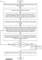
- a flowchart 100 which sets forth operations involving the use of the N-octet message to enable the system 10 to implement identification/verification of the target device 26.
- the N-octet message decoding algorithm is provided to the service processor 30 of the target device 26. This may occur when the target device 26 is initially installed in the data center or at some time thereafter.
- the mapping application 16 transmits a command to the rPDU 20 to begin the verification/discovery operation of a specific target device 26 coupled to AC outlet 24a.
- the rPDU controller 22 begins applying the sequence of PCP events (i.e., commands) to the selected AC outlet 24a on the rPDU 20.
- This causes a series of short duration AC power interruptions at the target device's AC input receptacle 32, which may be repeated in one, two or more different repetition patterns.
- these AC power supply interruptions are of sufficiently short duration that they do not cause loss of power or brownout condition that may result in rebooting of the target device 26, but they are still detectable by the input voltage monitoring subsystem 35 of the target device 26.
- the service processor 30 uses the input voltage monitoring subsystem 35 to monitor the AC input supply voltage at the target device's AC input receptacle 32.
- the service processor 30 calculates the 1 st order difference between the magnitudes of the present and previous voltage measurements, and then compares this calculated 1 st order difference to a predetermined voltage window threshold.
- the service processor 30 registers the PCP event as either a "0" bit or a "1" bit, depending upon the timestamp relative to the last registered PCP event, in accordance with the pulse distance bit encoding intervals known from its decoding algorithm 38.
- the service processor 30 checks if all bits of the encoded N-octet message have been decoded. If they have not, then operations 110 and 112 are repeated. Once all bytes have been decoded, the service processor 30 may store its test results, as indicated at operation 116, until the mapping application 16 polls the service processor 30, as indicated at operation 118, with a request for the results. Once the mapping application 16 has obtained the decoded message from the service processor 30 it may then determine if the bits reported by the service processor 30 correspond to the encoded message.
- the operations described above in connection with Figure 2 may be repeated for each AC power outlet 24a-24d of the rPDU 20, and for every rPDU in a data center.
- the identification/verification described in connection with Figure 2 may be performed on a periodic basis (e.g., monthly) or right after a new target device has being installed in the data center, or possibly in response to some triggering event (e.g., reconfiguration of a given rack with new/different equipment) to ensure that records detailing exactly what rPDU outlets are coupled to what data center devices are accurate and up to date.
- the use of low cost, electromechanical, bistable relays may be preferred. These may be integrated into the manufacture of the rPDU 20 if the rPDU does not already include suitable switching components for carrying out the needed short duration power switching.
- the periodic and repetitive power switching is at a duty cycle greater than required for typical switching applications with rPDUs.
- particular design considerations should preferably be met. These include, but are not limited to, protecting the contacts from destruction due to inrush current, protecting the contacts from arcing under heavy and/or low power factor loading conditions, and establishing initial power state after power cycle for proper device startup and commissioning. These factors may or may not require modification to some models of rPDUs currently being used in modern day data centers.
- a hybrid power control method may be used that comprises a parallel electrical connection between an electromechanical relay and solid-state switches, for example, triacs or anti-parallel SCRs.
- This more expensive solution would allow precise phase controlled switching to also modulate the voltage output.
- the relay contacts would first be opened so that the solid-state switches could be triggered on at various conduction angles and naturally commutated off to precisely control the voltage output without turning off completely for a full line cycle. This method would mitigate the risk of inadvertent re-booting the target device caused by a power loss or brownout condition. After the message is received, then the relay's contacts would engage to shunt the solid-state devices and reduce power dissipation.
- a solid-state only power control means is possible as well, but the continuous power dissipation may be an additional challenge to address.
- the system 10 and method may be used to identify/verify that a specific PDU is providing power to one or more specific data center devices.
- the input or branch circuits of the rack PDU 20 may utilize relay and/or solid-state switching to "broadcast" the encoded message simultaneously to numerous target devices. While the outlet identity cannot be resolved for unswitched AC outlet model PDUs, the PSN and a portion of the HID information can be transmitted and the power supplying relationship established.
- the service processor 30 being used to perform the message decoding
- this functionality could instead be performed by the main processor 28 of the target device 26, assuming the main processor 28 is able to access and use both the message decoding algorithm 38 and the input voltage monitoring subsystem 35.
- the target device 26 may communicate via a separate communications line 39b, as shown in Figure 1 , to communicate the decoded message to the main management system 12.
- the system 10 is not limited to use with only target devices that incorporate a service processor, although the presence of a service processor in the target device makes for an especially easy and elegant implementation.
- the present system 10 and method thus enables an identification/verification process to be carried out which quickly and easily enables a check to be made as to whether a specific target device is coupled to a specific AC outlet of a specific rPDU.
- the system 10 and method carries out this identification/verification process without re-booting the target device, and without interrupting operation of the target device in any way.
- An advantage is that the system 10 makes use of the existing service processor of the target device, which leaves the main controller/processor of the target device free to handle the applications and/or processing tasks which the target device is intended to handle.
- the system 10 further does not require any physical modifications to the target device, nor is it necessary for a data center worker to walk out to the target device (or the rPDU to which the N-octet message is being transmitted) and perform any type of reconfiguration of the controls on the target device.
Landscapes
- Engineering & Computer Science (AREA)
- Theoretical Computer Science (AREA)
- Power Engineering (AREA)
- General Engineering & Computer Science (AREA)
- General Physics & Mathematics (AREA)
- Physics & Mathematics (AREA)
- Computer Networks & Wireless Communication (AREA)
- Signal Processing (AREA)
- Human Computer Interaction (AREA)
- Quality & Reliability (AREA)
- Computer Security & Cryptography (AREA)
- Remote Monitoring And Control Of Power-Distribution Networks (AREA)
- Power Sources (AREA)
Claims (14)
- System (10) für mindestens eines der Folgenden, zum Identifizieren oder Überprüfen welches bestimmte Datenzentrumsgerät aus mehreren Datenzentrumsgeräten über einen Wechselstromausgang (24a-24d) einer Stromverteilungseinheit (20) mit Energie versorgt wird, wobei das System (10) aufweist:ein Algorithmusmodul zur Nachrichtenverschlüsselung;ein Algorithmusmodul zur Nachrichtenentschlüsselung;ein Eingangssignal-Überwachungsteilsystem (35) zur Überwachung eines Wechselstroms (AC)-Betriebssignals, das an die Geräte des Datenzentrums geliefert wird, wobei eines der Geräte des Datenzentrums ein mit AC betriebenes Zielgerät (26) aufweist,ein mit AC betriebenes Zielgerät (26) aufweisend;einen AC-Betriebseingang zum Empfangen des AC-Betriebssignals;einen Prozessor, der mit dem Eingangssignal-Überwachungsteilsystem (35) kommuniziert;eine Stromverteilereinheit (power distribution unit (PDU)) (20) zur Bereitstellung des Wechselstrom (AC)-Betriebssignals an das mit AC betriebene Zielgerät (26), wobei die PDU (20) eine Steuerung (22) aufweist, wobei die Steuerung (14) mit dem Verschlüsselungsalgorithmus der Nachrichten (22b) kommuniziert und konfiguriert ist, um den Verschlüsselungsalgorithmus der Nachrichten (22b) zu verwenden, um eine verschlüsselte Nachricht gemäß einem vorgegebenen Arbeitstaktprofil (Power Cycle Profile (PCP))-Ereignis zu erstellen, wobei das PCP-Ereignis von der PDU (20) implementiert wird, die ein moduliertes AC-Betriebssignal erzeugt, das mit dem PCP-Ereignis verschlüsselt ist, und wobei das modulierte AC-Betriebssignal ausreichend in der Größe ist, um keinen Stromausfalls- oder einen Spannungseinbruchs-Zustand zu verursachen, der einen Neustart eines mit AC betriebenen Datenzentrumsgeräts verursacht; unddas Zielgerät (26) ist außerdem konfiguriert, um das PCP-Ereignis zu analysieren, wenn das modulierte AC-Betriebssignal empfangen wird, und daraus eine verschlüsselte Nachricht zu erstellen, die verwendet wird, um anzuzeigen, ob der AC-Ausgang (24a-24d) der PDU (20) das Zielgerät (26) mit Strom versorgt.
- System (10) von Anspruch 1, das außerdem ein Hauptverwaltungssystem (12) in Kommunikation mit der PDU (20) aufweist und konfiguriert ist, um eine Nachricht an die PDU (20) zu übertragen, um einen Erkennungsprozess durch Implementieren der Veränderung des AC-Betriebssignal entsprechend dem PCP-Ereignis zu starten.
- System (10) von Anspruch 2, wobei das Zielgerät (26) ferner ein Kommunikationsanschluss (40) zum Zurücksenden der verschlüsselten Nachricht an das Hauptverwaltungssystem (12) aufweist.
- System (10) von Anspruch 3, wobei der Prozessor des Zielgeräts (26) einen Dienstprozessor (30) aufweist und wobei der Kommunikationsanschluss (40) in Kommunikation mit dem Serviceprozessor (30) ist.
- System (10) von Anspruch 1, wobei das PCP-Ereignis eine Reihe von Stromunterbrechungen vorgegebener Dauer in dem modulierten AC-Betriebssignal verursacht, das an das Zielgerät (26) angelegt wird.
- System (10) von Anspruch 5, wobei die PDU (20) konfiguriert ist, um das PCP-Ereignis mehrmals und in unterschiedlichen Zeitintervallen zu wiederholen während das modulierte AC-Betriebssignal an das Zielgerät (26) geliefert wird.
- System (10) von Anspruch 6, wobei das PCP-Ereignis zu einem, nicht mehr als 10 % messbaren RMS-Spannungsabfall vom minimalen Nennwert des AC-Betriebssignals führt, während das modulierte AC-Betriebssignal dem Zielgerät (26) zugeführt wird.
- System (10) von Anspruch 7, wobei die PDU (20) konfiguriert ist, um Impulsdistanz-Bit-Kodierung zu verwenden, um eine verschlüsselte Nachricht zu erstellen, die aus mehreren Einsen-Bits und Nullen-Bits besteht, die gemeinsam definieren, wann Befehle zum Ausführen des PCP-Ereignisses aufzutreten sind.
- System (10) von Anspruch 8, wobei die verschlüsselte Nachricht mit den Einsen-Bits und den Nullen-Bits weiterhin konfiguriert sind, um die Befehle zu veranlassen, das PCP-Ereignis auszuführen, um in ausgewählten, variablen Zeitintervallen aufzutreten.
- System (10) von Anspruch 9, wobei die verschlüsselte Nachricht mindestens eins von Folgenden aufweist:eine Produktseriennummer des Zielgeräts (26);eine Hardware-Identifikation einschließlich mindestens einer Zweig-/Steckerbuchsen-Indexnummer;einen Wert der zyklischen Redundanzprüfung (Cyclic Redundancy Check (CRC)); odereinen Bildwechselfrequenzwert.
- System (10) von Anspruch 10, wobei die verschlüsselte Nachricht alles von der Produktseriennummer, der Hardware-Identifikation, dem Wert der zyklische Redundanzprüfung (CRC) und von dem Wert der Bildwechselfrequenz enthält.
- System (10) von Anspruch 11, wobei das System (10) des Zielgeräts (26) konfiguriert ist, um den Verschlüsselungsalgorithmus für Nachrichten (22b) zu verwenden, um:Bits der Nachricht zu verschlüsseln;die Bits in 8-Bit-Pakete zu packen;einen Wert der zyklischen Redundanzprüfung der 8-Bit-Pakete zu berechnen; undden berechneten Wert der zyklischen Redundanzprüfung mit dem CRC-Wert von der verschlüsselten Nachricht zu vergleichen, um zu überprüfen, ob die verschlüsselte Nachricht korrekt empfangen wurde.
- System (10) von Anspruch 12, wobei das Zielgerät (26) außerdem einen Kommunikationsanschluss (40) zum Zurücksenden der verschlüsselten Nachricht an das Hauptverwaltungssystem (12) aufweist; und
wobei das Hauptverwaltungssystem (12) eine Kartierungsanwendung (16) aufweist, die konfiguriert ist, um festzustellen, ob die verschlüsselte Nachricht mit der vom Zielgerät (26) empfangenen entschlüsselten Nachricht übereinstimmt. - Verfahren, um zumindest eins davon, entweder Identifizieren oder Überprüfen welches bestimmte Datenzentrumsgerät aus mehreren Datenzentrumsgeräten von einen bestimmten AC-Betriebsausgang (24a-24d) einer Stromverteilungseinheit (PDU) (20) betrieben wird, wobei das Verfahren aufweist:Verwenden der PDU (20), um ein Wechselstrom (AC)-Betriebssignal an mindestens ein Zielgerät (26) über den spezifischen AC-Betriebsausgang (24a-24d) der PDU (20) zu liefern;Verwenden der PDU (20) und ein Algorithmusmodul zur Nachrichtenverschlüsselung zum Verändern des AC-Betriebssignal gemäß eines vordefinierten Arbeitstaktprofil (Power Cycle Profile (PCP))-Ereignisses, das gemäß einem vorgegebenen Wiederholungsmuster der variierenden Zeitintervallen mehrere Male wiederholt wird, und wobei die PCP-Ereignisse eine verschlüsselte Nachricht darstellen, wobei das modulierte AC-Betriebssignal ausreichend in der Stärke ist, um keine Verringerung im AC-Betrieb zu verursachen, der ausreicht, um einen Neustart des mindestens einen Zielgeräts (26) zu bewirken, das durch das AC-Betriebssignal betrieben wird;Verwenden des Zielgeräts (26), um die verschlüsselte Nachricht über das AC-Betriebssignal zu erhalten;Veranlassen des Zielgeräts (26) ein Algorithmusmodul zur Nachrichtenentschlüsselung zu verwenden, um die verschlüsselte Nachricht zu entschlüsseln, um eine entschlüsselte Nachricht zu erzeugen; undVerwenden der entschlüsselten Nachricht, um zu bestimmen, ob das Zielgerät (26) das AC-Betriebssignal von dem spezifischen AC-Betriebsausgang (24a-24d) der PDU (20) erhält.
Applications Claiming Priority (3)
| Application Number | Priority Date | Filing Date | Title |
|---|---|---|---|
| US201862744477P | 2018-10-11 | 2018-10-11 | |
| US16/552,673 US11216047B2 (en) | 2018-10-11 | 2019-08-27 | System and method for detecting relationship between intelligent power strip and device connected thereto |
| PCT/US2019/052281 WO2020076475A1 (en) | 2018-10-11 | 2019-09-20 | System and method for detecting relationship between intelligent power strip and device connected thereto |
Publications (3)
| Publication Number | Publication Date |
|---|---|
| EP3844594A1 EP3844594A1 (de) | 2021-07-07 |
| EP3844594A4 EP3844594A4 (de) | 2022-06-15 |
| EP3844594B1 true EP3844594B1 (de) | 2024-11-13 |
Family
ID=70160250
Family Applications (1)
| Application Number | Title | Priority Date | Filing Date |
|---|---|---|---|
| EP19871232.5A Active EP3844594B1 (de) | 2018-10-11 | 2019-09-20 | System und verfahren zur feststellung der beziehung zwischen einer intelligenten steckerleiste und damit verbundener vorrichtung |
Country Status (4)
| Country | Link |
|---|---|
| US (1) | US11216047B2 (de) |
| EP (1) | EP3844594B1 (de) |
| CN (1) | CN112867978B (de) |
| WO (1) | WO2020076475A1 (de) |
Families Citing this family (5)
| Publication number | Priority date | Publication date | Assignee | Title |
|---|---|---|---|---|
| US11347193B2 (en) * | 2020-02-15 | 2022-05-31 | International Business Machines Corporation | Automating reactive impedance measurements |
| US12210620B2 (en) * | 2021-03-16 | 2025-01-28 | Intel Corporation | Apparatus and method to detect power supply security attack and risk mitigation |
| CN114760224A (zh) * | 2021-12-24 | 2022-07-15 | 中国银联股份有限公司 | 用于监控网络通道的状态的系统、方法、设备和存储介质 |
| LU501560B1 (de) * | 2022-02-28 | 2023-08-28 | Phoenix Contact Gmbh & Co | Technik zur Feststellung einer Leistungsbeschaltung |
| CN114598038A (zh) * | 2022-05-10 | 2022-06-07 | 青岛鼎信通讯股份有限公司 | 一种适用于低压台区的特征电流识别方法 |
Family Cites Families (50)
| Publication number | Priority date | Publication date | Assignee | Title |
|---|---|---|---|---|
| US4344076A (en) * | 1979-06-29 | 1982-08-10 | Sangamo-Weston, Inc. | Feedback sensor for remote receiver in a power transmission system |
| US5136528A (en) * | 1989-11-14 | 1992-08-04 | Raytheon Company | Maintenance and operational simulators |
| JPH0546495A (ja) * | 1991-08-09 | 1993-02-26 | Ricoh Co Ltd | データ処理装置 |
| US5689230A (en) * | 1995-11-09 | 1997-11-18 | Motoral, Inc. | Energy monitoring and control system using reverse transmission on AC line |
| CA2353870A1 (en) * | 1998-10-23 | 2000-05-04 | Royal Thoughts L.L.C. | Bi-directional wireless detection system |
| WO2000046923A1 (en) * | 1999-02-04 | 2000-08-10 | Electric Power Research Institute, Inc. | Apparatus and method for implementing digital communications on a power line |
| US6275144B1 (en) * | 2000-07-11 | 2001-08-14 | Telenetwork, Inc. | Variable low frequency offset, differential, ook, high-speed power-line communication |
| US6377163B1 (en) * | 2000-09-21 | 2002-04-23 | Home Touch Lighting Systems Llc | Power line communication circuit |
| US6771164B1 (en) * | 2002-09-05 | 2004-08-03 | Nrc Corporation | Automatic identification of local devices |
| US7333000B2 (en) | 2004-11-12 | 2008-02-19 | Afco Systems Development, Inc. | Tracking system and method for electrically powered equipment |
| US7456588B2 (en) * | 2006-06-05 | 2008-11-25 | Osram Sylvania Inc. | Arrangement and method for providing power line communication from an AC power source to a circuit for powering a load, and electronic ballasts therefor |
| EP1990929A1 (de) * | 2007-05-08 | 2008-11-12 | Feelux Co., Ltd. | Netzkommunikationsgerät sowie Verfahren und Vorrichtung zur Steuerung von Elektrogeräten |
| US8880907B2 (en) | 2007-06-21 | 2014-11-04 | Schneider Electric It Corporation | Method and system for determining physical location of equipment |
| US8080900B2 (en) * | 2007-07-18 | 2011-12-20 | Exaflop Llc | Direct-coupled IT load |
| AU2009228204B2 (en) | 2008-03-26 | 2015-01-15 | Zonit Structured Solutions, Llc | Power distribution systems and methodology |
| US8713342B2 (en) * | 2008-04-30 | 2014-04-29 | Raritan Americas, Inc. | System and method for efficient association of a power outlet and device |
| US9213380B2 (en) | 2008-06-09 | 2015-12-15 | Lenovo Enterprise Solutions (Singapore) Pte. Ltd. | Mapping computers and ports of power distribution units in a data center |
| US8886985B2 (en) | 2008-07-07 | 2014-11-11 | Raritan Americas, Inc. | Automatic discovery of physical connectivity between power outlets and IT equipment |
| US8504857B1 (en) * | 2008-09-30 | 2013-08-06 | Emc Corporation | Programmable availability for a high availability system |
| US10223907B2 (en) * | 2008-11-14 | 2019-03-05 | Apple Inc. | System and method for capturing remote control device command signals |
| US8635484B2 (en) * | 2009-03-18 | 2014-01-21 | Hewlett-Packard Development Company, L.P. | Event based correlation of power events |
| EP2411888A4 (de) | 2009-03-25 | 2014-05-14 | Hewlett Packard Development Co | Stromverteilungseinheits-einrichtungskorrelation |
| CN201726421U (zh) * | 2010-01-11 | 2011-01-26 | 深圳市同洲电子股份有限公司 | 电缆调制解调器及控制电缆调制解调器低功耗运行的装置 |
| KR101047511B1 (ko) * | 2010-03-10 | 2011-07-07 | 최인숙 | 전력전송구간을 분할하여 데이터 신호를 전송하는 전력선 통신방법 |
| DK2372861T3 (da) * | 2010-04-01 | 2013-03-25 | Racktivity Nv | Styringsenhed til datacenter med dynamisk belastningsudligning |
| ES2488125T3 (es) * | 2010-09-09 | 2014-08-26 | Racktivity Nv | Unidad de distribución de potencia con función de osciloscopio |
| US20120083934A1 (en) * | 2010-09-30 | 2012-04-05 | Sharp Laboratories Of America, Inc. | Monitoring and controlling energy in an office environment |
| US8587223B2 (en) * | 2010-10-19 | 2013-11-19 | General Electric Company | Power line communication method and apparatus for lighting control |
| US9541585B2 (en) * | 2010-12-15 | 2017-01-10 | Nec Corporation | Method and system for identifying at least one electrically powered device by a power supply device via a powerline connection |
| WO2012128912A2 (en) * | 2011-03-18 | 2012-09-27 | Avocent | System and method for real time detection and correlation of devices and power outlets |
| US8639459B1 (en) * | 2011-03-30 | 2014-01-28 | Amazon Technologies, Inc. | System and method for monitoring power distribution units |
| US10025337B2 (en) * | 2011-12-16 | 2018-07-17 | Schneider Electric USA, Inc. | Method and system for managing an electrical distribution system in a facility |
| US9703342B2 (en) | 2012-02-10 | 2017-07-11 | Server Technology, Inc. | System and method for configuring plurality of linked power distribution units in which configuration data of the linked power distribution units are accessible by the remote system |
| US8972753B2 (en) * | 2012-02-14 | 2015-03-03 | International Business Machines Corporation | Determining suitability for disconnection from power outlet of a power distribution unit based on status of power supplies of a hardware device |
| CN102881134A (zh) * | 2012-09-14 | 2013-01-16 | 宁波思特机电有限公司 | 一种节能多电源无线定时控制系统 |
| WO2014059289A1 (en) * | 2012-10-11 | 2014-04-17 | Avocent Huntsville Corp. | System and method for tracking assets incorporating wireless network |
| US8792569B2 (en) * | 2012-12-21 | 2014-07-29 | International Business Machines Corporation | Power distribution system utilizing digital communications to determine the configuration thereof |
| US9058156B2 (en) * | 2012-12-26 | 2015-06-16 | Lenovo Enterprise Solutions (Singapore) Pte. Ltd. | Determining redundancy in a power distribution system |
| US9692231B2 (en) * | 2013-09-06 | 2017-06-27 | Amazon Technologies, Inc. | Managing power feeds through waveform monitoring |
| US9236909B2 (en) * | 2013-12-19 | 2016-01-12 | Stmicroelectronics, Inc. | Zero standby power for powerline communication devices |
| US20150220124A1 (en) | 2014-02-05 | 2015-08-06 | Microsoft Corporation | Power connectivity monitoring for computing systems |
| EP3198792B1 (de) | 2014-09-25 | 2018-06-20 | Microsoft Technology Licensing, LLC | Automatisiertes eigenständiges bootstrapping von hardwareinventar |
| US10833940B2 (en) | 2015-03-09 | 2020-11-10 | Vapor IO Inc. | Autonomous distributed workload and infrastructure scheduling |
| US10250032B2 (en) * | 2015-04-24 | 2019-04-02 | Vertiv Corporation | Intelligent power strip with management of bistable relays to reduce current in-rush |
| WO2017011528A1 (en) * | 2015-07-13 | 2017-01-19 | Maxim Intergrated Products, Inc. | Systems and methods for dc power line communication in a photovoltaic system |
| US10236648B2 (en) * | 2016-06-01 | 2019-03-19 | Server Technology, Inc. | Power distribution unit system incorporating smart cables and adapters |
| JP6662220B2 (ja) * | 2016-06-29 | 2020-03-11 | 富士通株式会社 | 情報処理システム、情報処理装置、位置特定方法及び位置特定プログラム |
| US10642321B2 (en) * | 2017-01-25 | 2020-05-05 | Oracle International Corporation | Power distribution unit self-identification |
| US20180373548A1 (en) * | 2017-06-26 | 2018-12-27 | Sunbird Software, Inc. | System And Method For Configuring Equipment That Is Reliant On A Power Distribution System |
| US11075897B2 (en) * | 2017-10-20 | 2021-07-27 | Vertiv It Systems, Inc. | System and method for communicating with a service processor |
-
2019
- 2019-08-27 US US16/552,673 patent/US11216047B2/en active Active
- 2019-09-20 EP EP19871232.5A patent/EP3844594B1/de active Active
- 2019-09-20 WO PCT/US2019/052281 patent/WO2020076475A1/en not_active Ceased
- 2019-09-20 CN CN201980066870.XA patent/CN112867978B/zh active Active
Also Published As
| Publication number | Publication date |
|---|---|
| US20200117249A1 (en) | 2020-04-16 |
| US11216047B2 (en) | 2022-01-04 |
| EP3844594A4 (de) | 2022-06-15 |
| WO2020076475A1 (en) | 2020-04-16 |
| CN112867978A (zh) | 2021-05-28 |
| CN112867978B (zh) | 2024-07-12 |
| EP3844594A1 (de) | 2021-07-07 |
Similar Documents
| Publication | Publication Date | Title |
|---|---|---|
| EP3844594B1 (de) | System und verfahren zur feststellung der beziehung zwischen einer intelligenten steckerleiste und damit verbundener vorrichtung | |
| US8108723B2 (en) | Triggered restart mechanism for failure recovery in power over ethernet | |
| US9934119B2 (en) | Rogue hardware detection through power monitoring | |
| EP4351093A1 (de) | Übertragung von impulsleistung und daten über ein drahtpaar | |
| CN106998253B (zh) | 以太网络供电系统的供电设备及供电方法 | |
| WO2008118888A1 (en) | Methods and apparatus providing advanced classification for power over ethernet | |
| CN102136915B (zh) | 一种增强以太网供电安全性的方法及装置 | |
| US8499185B2 (en) | Determining redundancy of power feeds connecting a server to a power supply | |
| US20100002879A1 (en) | Method and apparatus for reducing communication system downtime when configuring a cryptographic system of the communication system | |
| CN103443735A (zh) | 用于设备和电力输出口的实时检测和关联的系统和方法 | |
| TWI594598B (zh) | 乙太網路供電系統的供電設備及供電方法(一) | |
| CN106341237A (zh) | 基于poe系统的pse供电方法及装置 | |
| CN108604993B (zh) | 对于dc电力供给设备的电力下垂补偿 | |
| WO2013001395A1 (en) | Active power identification for load monitoring system | |
| CN105423486A (zh) | 电加热器的启动控制方法和装置 | |
| CN103138946A (zh) | 一种poe供电管理方法及装置 | |
| WO2011066876A1 (en) | Data center management unit with protection against network isolation | |
| CN114937971A (zh) | 一种用电插座的安全保护方法及装置 | |
| CN112600300B (zh) | 一种针对变电站中的二次设备的配置系统 | |
| US10592879B2 (en) | System for distributing electrical energy | |
| WO2018195538A1 (en) | Low voltage power distribution system | |
| CN114966311B (zh) | 闪断状态检测电路、检测方法及电子设备、控制方法 | |
| JP2018102024A (ja) | 作業用接地外し確認装置及び制御システム | |
| US20250172979A1 (en) | Apparatus and method for discovering power connections using power patterns | |
| CN105490820B (zh) | 一种poe供电方法和装置 |
Legal Events
| Date | Code | Title | Description |
|---|---|---|---|
| STAA | Information on the status of an ep patent application or granted ep patent |
Free format text: STATUS: THE INTERNATIONAL PUBLICATION HAS BEEN MADE |
|
| STAA | Information on the status of an ep patent application or granted ep patent |
Free format text: STATUS: REQUEST FOR EXAMINATION WAS MADE |
|
| PUAI | Public reference made under article 153(3) epc to a published international application that has entered the european phase |
Free format text: ORIGINAL CODE: 0009012 |
|
| 17P | Request for examination filed |
Effective date: 20210330 |
|
| AK | Designated contracting states |
Kind code of ref document: A1 Designated state(s): AL AT BE BG CH CY CZ DE DK EE ES FI FR GB GR HR HU IE IS IT LI LT LU LV MC MK MT NL NO PL PT RO RS SE SI SK SM TR |
|
| DAV | Request for validation of the european patent (deleted) | ||
| DAX | Request for extension of the european patent (deleted) | ||
| A4 | Supplementary search report drawn up and despatched |
Effective date: 20220517 |
|
| RIC1 | Information provided on ipc code assigned before grant |
Ipc: G06F 11/10 20060101ALI20220511BHEP Ipc: G06F 11/30 20060101ALI20220511BHEP Ipc: G06F 1/28 20060101AFI20220511BHEP |
|
| GRAP | Despatch of communication of intention to grant a patent |
Free format text: ORIGINAL CODE: EPIDOSNIGR1 |
|
| STAA | Information on the status of an ep patent application or granted ep patent |
Free format text: STATUS: GRANT OF PATENT IS INTENDED |
|
| INTG | Intention to grant announced |
Effective date: 20240628 |
|
| GRAS | Grant fee paid |
Free format text: ORIGINAL CODE: EPIDOSNIGR3 |
|
| GRAA | (expected) grant |
Free format text: ORIGINAL CODE: 0009210 |
|
| STAA | Information on the status of an ep patent application or granted ep patent |
Free format text: STATUS: THE PATENT HAS BEEN GRANTED |
|
| AK | Designated contracting states |
Kind code of ref document: B1 Designated state(s): AL AT BE BG CH CY CZ DE DK EE ES FI FR GB GR HR HU IE IS IT LI LT LU LV MC MK MT NL NO PL PT RO RS SE SI SK SM TR |
|
| REG | Reference to a national code |
Ref country code: GB Ref legal event code: FG4D |
|
| REG | Reference to a national code |
Ref country code: CH Ref legal event code: EP |
|
| REG | Reference to a national code |
Ref country code: IE Ref legal event code: FG4D |
|
| REG | Reference to a national code |
Ref country code: DE Ref legal event code: R096 Ref document number: 602019062067 Country of ref document: DE |
|
| REG | Reference to a national code |
Ref country code: LT Ref legal event code: MG9D |
|
| REG | Reference to a national code |
Ref country code: NL Ref legal event code: MP Effective date: 20241113 |
|
| REG | Reference to a national code |
Ref country code: GB Ref legal event code: 732E Free format text: REGISTERED BETWEEN 20250313 AND 20250319 |
|
| PG25 | Lapsed in a contracting state [announced via postgrant information from national office to epo] |
Ref country code: HR Free format text: LAPSE BECAUSE OF FAILURE TO SUBMIT A TRANSLATION OF THE DESCRIPTION OR TO PAY THE FEE WITHIN THE PRESCRIBED TIME-LIMIT Effective date: 20241113 Ref country code: PT Free format text: LAPSE BECAUSE OF FAILURE TO SUBMIT A TRANSLATION OF THE DESCRIPTION OR TO PAY THE FEE WITHIN THE PRESCRIBED TIME-LIMIT Effective date: 20250313 Ref country code: IS Free format text: LAPSE BECAUSE OF FAILURE TO SUBMIT A TRANSLATION OF THE DESCRIPTION OR TO PAY THE FEE WITHIN THE PRESCRIBED TIME-LIMIT Effective date: 20250313 |
|
| PG25 | Lapsed in a contracting state [announced via postgrant information from national office to epo] |
Ref country code: NL Free format text: LAPSE BECAUSE OF FAILURE TO SUBMIT A TRANSLATION OF THE DESCRIPTION OR TO PAY THE FEE WITHIN THE PRESCRIBED TIME-LIMIT Effective date: 20241113 Ref country code: FI Free format text: LAPSE BECAUSE OF FAILURE TO SUBMIT A TRANSLATION OF THE DESCRIPTION OR TO PAY THE FEE WITHIN THE PRESCRIBED TIME-LIMIT Effective date: 20241113 |
|
| PG25 | Lapsed in a contracting state [announced via postgrant information from national office to epo] |
Ref country code: BG Free format text: LAPSE BECAUSE OF FAILURE TO SUBMIT A TRANSLATION OF THE DESCRIPTION OR TO PAY THE FEE WITHIN THE PRESCRIBED TIME-LIMIT Effective date: 20241113 |
|
| PG25 | Lapsed in a contracting state [announced via postgrant information from national office to epo] |
Ref country code: ES Free format text: LAPSE BECAUSE OF FAILURE TO SUBMIT A TRANSLATION OF THE DESCRIPTION OR TO PAY THE FEE WITHIN THE PRESCRIBED TIME-LIMIT Effective date: 20241113 |
|
| PG25 | Lapsed in a contracting state [announced via postgrant information from national office to epo] |
Ref country code: NO Free format text: LAPSE BECAUSE OF FAILURE TO SUBMIT A TRANSLATION OF THE DESCRIPTION OR TO PAY THE FEE WITHIN THE PRESCRIBED TIME-LIMIT Effective date: 20250213 |
|
| PG25 | Lapsed in a contracting state [announced via postgrant information from national office to epo] |
Ref country code: LV Free format text: LAPSE BECAUSE OF FAILURE TO SUBMIT A TRANSLATION OF THE DESCRIPTION OR TO PAY THE FEE WITHIN THE PRESCRIBED TIME-LIMIT Effective date: 20241113 Ref country code: GR Free format text: LAPSE BECAUSE OF FAILURE TO SUBMIT A TRANSLATION OF THE DESCRIPTION OR TO PAY THE FEE WITHIN THE PRESCRIBED TIME-LIMIT Effective date: 20250214 |
|
| PG25 | Lapsed in a contracting state [announced via postgrant information from national office to epo] |
Ref country code: PL Free format text: LAPSE BECAUSE OF FAILURE TO SUBMIT A TRANSLATION OF THE DESCRIPTION OR TO PAY THE FEE WITHIN THE PRESCRIBED TIME-LIMIT Effective date: 20241113 |
|
| PG25 | Lapsed in a contracting state [announced via postgrant information from national office to epo] |
Ref country code: RS Free format text: LAPSE BECAUSE OF FAILURE TO SUBMIT A TRANSLATION OF THE DESCRIPTION OR TO PAY THE FEE WITHIN THE PRESCRIBED TIME-LIMIT Effective date: 20250213 |
|
| RAP2 | Party data changed (patent owner data changed or rights of a patent transferred) |
Owner name: VERTIV CORPORATION |
|
| PG25 | Lapsed in a contracting state [announced via postgrant information from national office to epo] |
Ref country code: SM Free format text: LAPSE BECAUSE OF FAILURE TO SUBMIT A TRANSLATION OF THE DESCRIPTION OR TO PAY THE FEE WITHIN THE PRESCRIBED TIME-LIMIT Effective date: 20241113 |
|
| PG25 | Lapsed in a contracting state [announced via postgrant information from national office to epo] |
Ref country code: DK Free format text: LAPSE BECAUSE OF FAILURE TO SUBMIT A TRANSLATION OF THE DESCRIPTION OR TO PAY THE FEE WITHIN THE PRESCRIBED TIME-LIMIT Effective date: 20241113 |
|
| PG25 | Lapsed in a contracting state [announced via postgrant information from national office to epo] |
Ref country code: EE Free format text: LAPSE BECAUSE OF FAILURE TO SUBMIT A TRANSLATION OF THE DESCRIPTION OR TO PAY THE FEE WITHIN THE PRESCRIBED TIME-LIMIT Effective date: 20241113 |
|
| PG25 | Lapsed in a contracting state [announced via postgrant information from national office to epo] |
Ref country code: RO Free format text: LAPSE BECAUSE OF FAILURE TO SUBMIT A TRANSLATION OF THE DESCRIPTION OR TO PAY THE FEE WITHIN THE PRESCRIBED TIME-LIMIT Effective date: 20241113 |
|
| PG25 | Lapsed in a contracting state [announced via postgrant information from national office to epo] |
Ref country code: SK Free format text: LAPSE BECAUSE OF FAILURE TO SUBMIT A TRANSLATION OF THE DESCRIPTION OR TO PAY THE FEE WITHIN THE PRESCRIBED TIME-LIMIT Effective date: 20241113 |
|
| PG25 | Lapsed in a contracting state [announced via postgrant information from national office to epo] |
Ref country code: CZ Free format text: LAPSE BECAUSE OF FAILURE TO SUBMIT A TRANSLATION OF THE DESCRIPTION OR TO PAY THE FEE WITHIN THE PRESCRIBED TIME-LIMIT Effective date: 20241113 |
|
| REG | Reference to a national code |
Ref country code: DE Ref legal event code: R097 Ref document number: 602019062067 Country of ref document: DE |
|
| PG25 | Lapsed in a contracting state [announced via postgrant information from national office to epo] |
Ref country code: SE Free format text: LAPSE BECAUSE OF FAILURE TO SUBMIT A TRANSLATION OF THE DESCRIPTION OR TO PAY THE FEE WITHIN THE PRESCRIBED TIME-LIMIT Effective date: 20241113 |
|
| PLBE | No opposition filed within time limit |
Free format text: ORIGINAL CODE: 0009261 |
|
| STAA | Information on the status of an ep patent application or granted ep patent |
Free format text: STATUS: NO OPPOSITION FILED WITHIN TIME LIMIT |
|
| REG | Reference to a national code |
Ref country code: DE Ref legal event code: R081 Ref document number: 602019062067 Country of ref document: DE Owner name: VERTIV CORPORATION, WESTERVILLE, US Free format text: FORMER OWNER: VERTIV IT SYSTEMS, INC., HUNTSVILLE, AL, US |
|
| REG | Reference to a national code |
Ref country code: CH Ref legal event code: U11 Free format text: ST27 STATUS EVENT CODE: U-0-0-U10-U11 (AS PROVIDED BY THE NATIONAL OFFICE) Effective date: 20251001 |
|
| PGFP | Annual fee paid to national office [announced via postgrant information from national office to epo] |
Ref country code: DE Payment date: 20250929 Year of fee payment: 7 |
|
| PGFP | Annual fee paid to national office [announced via postgrant information from national office to epo] |
Ref country code: IT Payment date: 20250919 Year of fee payment: 7 |
|
| REG | Reference to a national code |
Ref country code: AT Ref legal event code: PC Ref document number: 1742164 Country of ref document: AT Kind code of ref document: T Owner name: VERTIV CORPORATION, US Effective date: 20250904 |
|
| PGFP | Annual fee paid to national office [announced via postgrant information from national office to epo] |
Ref country code: GB Payment date: 20250929 Year of fee payment: 7 |
|
| PGFP | Annual fee paid to national office [announced via postgrant information from national office to epo] |
Ref country code: FR Payment date: 20250925 Year of fee payment: 7 Ref country code: AT Payment date: 20250929 Year of fee payment: 7 |
|
| 26N | No opposition filed |
Effective date: 20250814 |
|
| PGFP | Annual fee paid to national office [announced via postgrant information from national office to epo] |
Ref country code: CH Payment date: 20251001 Year of fee payment: 7 |
|
| REG | Reference to a national code |
Ref country code: CH Ref legal event code: R18 Free format text: ST27 STATUS EVENT CODE: U-0-0-R10-R18 (AS PROVIDED BY THE NATIONAL OFFICE) Effective date: 20260225 |
|
| REG | Reference to a national code |
Ref country code: AT Ref legal event code: UEP Ref document number: 1742164 Country of ref document: AT Kind code of ref document: T Effective date: 20241113 |