EP3844030B1 - Kühlvorrichtung für bauteile in einem fahrzeug - Google Patents
Kühlvorrichtung für bauteile in einem fahrzeug Download PDFInfo
- Publication number
- EP3844030B1 EP3844030B1 EP19755837.2A EP19755837A EP3844030B1 EP 3844030 B1 EP3844030 B1 EP 3844030B1 EP 19755837 A EP19755837 A EP 19755837A EP 3844030 B1 EP3844030 B1 EP 3844030B1
- Authority
- EP
- European Patent Office
- Prior art keywords
- cooling device
- diffuser
- plate
- fluid
- vehicle
- Prior art date
- Legal status (The legal status is an assumption and is not a legal conclusion. Google has not performed a legal analysis and makes no representation as to the accuracy of the status listed.)
- Active
Links
Images


Classifications
-
- B—PERFORMING OPERATIONS; TRANSPORTING
- B60—VEHICLES IN GENERAL
- B60R—VEHICLES, VEHICLE FITTINGS, OR VEHICLE PARTS, NOT OTHERWISE PROVIDED FOR
- B60R16/00—Electric or fluid circuits specially adapted for vehicles and not otherwise provided for; Arrangement of elements of electric or fluid circuits specially adapted for vehicles and not otherwise provided for
- B60R16/02—Electric or fluid circuits specially adapted for vehicles and not otherwise provided for; Arrangement of elements of electric or fluid circuits specially adapted for vehicles and not otherwise provided for electric constitutive elements
- B60R16/023—Electric or fluid circuits specially adapted for vehicles and not otherwise provided for; Arrangement of elements of electric or fluid circuits specially adapted for vehicles and not otherwise provided for electric constitutive elements for transmission of signals between vehicle parts or subsystems
- B60R16/0239—Electronic boxes
-
- H—ELECTRICITY
- H05—ELECTRIC TECHNIQUES NOT OTHERWISE PROVIDED FOR
- H05K—PRINTED CIRCUITS; CASINGS OR CONSTRUCTIONAL DETAILS OF ELECTRIC APPARATUS; MANUFACTURE OF ASSEMBLAGES OF ELECTRICAL COMPONENTS
- H05K7/00—Constructional details common to different types of electric apparatus
- H05K7/20—Modifications to facilitate cooling, ventilating, or heating
- H05K7/20845—Modifications to facilitate cooling, ventilating, or heating for automotive electronic casings
- H05K7/20863—Forced ventilation, e.g. on heat dissipaters coupled to components
Definitions
- the invention relates to a cooling device for cooling a component of a vehicle, in particular a land vehicle.
- the invention also relates to a vehicle and a use.
- Cooling certain components, e.g. electronic components, in a vehicle may be necessary to avoid acute damage from overheating and to avoid shortening the service life of the components due to increased thermal stress. This also applies, for example, to components of a high-performance computer, both in a vehicle and for stationary systems. Some of these cooling devices are complex to manufacture; some cannot provide a lower temperature than the ambient temperature.
- a cooling device for cooling a component of a vehicle which has a first, thermally conductive plate that is adjacent to the component.
- Such components can be, for example, electronic components or electronic components such as control computers, Roof antennas, front cameras and a variety of other modules or components.
- a single component or several components can be adjacent to the first plate.
- the component and the first, thermally conductive plate are adjacent in such a way that thermal energy can be exchanged between the component and the plate. In particular, a low thermal resistance can be provided between these elements. Since the plate is thermally conductive, the thermal energy can be passed on via the plate. In one embodiment, the contact resistance between the component and the plate can be reduced by certain measures, e.g. by a thermal paste.
- the vehicle is, for example, a motor vehicle such as a car, bus or truck, or a rail vehicle, a ship, or an aircraft such as a helicopter or airplane.
- the cooling device further comprises a second plate which is arranged substantially parallel to the first plate.
- the second plate can also be thermally conductive.
- the second plate can also consist of a part of the vehicle, e.g. a section of a vehicle roof.
- the second plate can be heat-insulating. This can be useful if the second plate is arranged near a hot part of the vehicle, e.g. near the engine. It is also not necessary for the second plate to be arranged exactly parallel to the first plate; rather, this arrangement should ensure good drainage of the fluid suitable for cooling. Channels can also be formed, or the drainage of the fluid can be controlled by means of baffles.
- the cooling device also has a diffuser which is arranged between the first plate and the second plate.
- the diffuser is permeable to the fluid, in particular permeable in several directions. It also offers a predefined resistance to the fluid.
- the cooling device also has a fluid supply that is designed to be connected to a fluid source at a first end and that is connected to the diffuser at a second end in such a way that a fluid can flow from the fluid source from the inside to the outside through the diffuser.
- the fluid source which is arranged at the first end of the fluid supply, supplies a fluid flow.
- the fluid supply is connected to the diffuser at the second end, for example to the center of the diffuser. Because the diffuser offers a predefined resistance to the fluid, an overpressure is created at the second end of the fluid supply. The diffuser essentially forces the fluid to expand and the fluid is thereby cooled (Joule-Thomson effect).
- the cooling device therefore provides a lower temperature than the ambient temperature.
- the fluid flows over the first, thermally conductive plate and thus ensures the distribution of the heat energy away from the first plate and thus the component that is adjacent to the first plate. It is precisely the combination of fluid expansion and flow that ensures efficient cooling of components.
- the diffuser has a centrally arranged cavity to which the fluid supply is connected.
- the centrally arranged cavity is not necessarily arranged coaxially to the edges of the diffuser;
- the cavity can also be arranged eccentrically.
- the cavity can be designed as a continuous passage, it can be designed as a blind hole or as a cavity.
- the advantage of a cavity is that it allows the diffusion directions of the fluid to be determined better than is the case with a simple introduction of the fluid supply into the diffuser.
- the walls of the cavity can be processed to further determine the diffusion properties, e.g. have a certain surface design, such as corrugation, or, at least partially, refined with certain materials, e.g. gold, in order to further improve, for example, corrosion resistance and/or heat conduction.
- the fluid supply has a passage which leads through the second plate to the diffuser and which is connected at a first end to the diffuser and at a second end via a line to the fluid source.
- the fluid is thus supplied through the passage in the second plate.
- the fluid supply has a line that is directly connected to the diffuser.
- the line therefore runs, at least partially, through the spacing between the first and second plates, which also serves to drain a fluid.
- the diffuser is connected to at least one of the plates in a form-fitting, force-fitting and/or material-fitting manner.
- the diffuser can be glued, welded, soldered, screwed, riveted or clamped between the plates to at least one of the plates.
- the connection to the first Plate can be thermally conductive, e.g. by means of thermally conductive adhesive.
- the diffuser can be designed with the first plate as a one-piece element.
- the diffuser and the first plate are designed as a one-piece element, wherein a transition, in particular a seamless transition, is realized in the element between the material of the diffuser and the material of the first plate. This embodiment has the advantage that it can be realized particularly cost-effectively; in addition, the embodiment has particularly good thermal conduction properties.
- the first plate is designed as a heat pipe. This further improves the heat transport of the heat pipe.
- the diffuser (40) is connected to at least one of the plates (20, 30) in a form-fitting, force-fitting and/or material-fitting manner or the diffuser (40) and the first plate (20) are designed as a one-piece element, wherein a transition, in particular a seamless transition, between the material of the diffuser (40) and the material of the first plate (20) is realized in the element.
- the diffuser is a sintered filter.
- the diffuser can have a plurality of thin webs, for example in the form of a brush, or cylinders, or even a labyrinth.
- the webs or cylinders can have diameters of less than 100 ⁇ m, in particular less than 10 ⁇ m.
- the fluid source is a compressor, in particular a seat compressor.
- a seat compressor has the advantage that it is already designed for use in vehicles, e.g. with regard to operating voltage or temperature range.
- the fluid source is located in a cooler part of the vehicle than the component.
- the fluid source can be located closer to the floor or in the area of the vehicle's forced ventilation.
- the placement of the component is often predetermined by its functionality; for example, an engine control unit will be located near the (hot) engine, or a roof antenna will be located in the area of the (potentially hot) vehicle roof.
- the fluid source has an overpressure between 0.05 and 1.0 bar, in particular between 0.1 and 0.3 bar.
- An overpressure in this range is technically quite simple and inexpensive to control, and standard lines can be used.
- the fluid is a gas, in particular air.
- gases or even liquids can be used.
- the first plate has a thermal conductivity of greater than 50 W/(m ⁇ K), in particular greater than 200 W/(m ⁇ K).
- a thermal conductivity in this range supports cooling in an efficient manner.
- Materials can be, for example, aluminum, aluminum alloys or copper.
- the first plate can also be a circuit board for electronic assemblies that is designed to be particularly thermally conductive; this can be achieved, for example, by means of fields of vias (through holes).
- thermal interface materials are arranged between the component and the first plate. These materials are also referred to as "Thermal Interface Material” (TIM)
- TIM Thermal Interface Material
- the materials include, for example, thermal pastes, thermally conductive adhesives or certain types of silicon pads.
- a further aspect of the invention relates to a use of a cooling device as described above and below for cooling automotive electronics, camera modules, e.g. in the area of the windshield of vehicles, or computers, in particular high-performance computers.
- a vehicle with a cooling device as described above is provided.
- Fig. 1 shows a vehicle 90 in whose roof area 92 a cooling device 10 is arranged.
- the cooling device 10 can be used, for example, to cool a car antenna 94.
- the car antenna 94 is arranged above the roof, the cooling device 10 below the roof.
- a compressor 55 is arranged, which serves as a fluid source 55 for the cooling device 10.
- the arrangement of the compressor 55 at this point can be motivated by the fact that the temperature at this point can in many cases be lower than in the roof area 92.
- the compressor 55 can also be arranged close to the cooling device 10.
- the compressor 55 is connected to the cooling device 10 via a line 57. Since the pressure generated by the compressor 55 is relatively low, the requirements for the pressure resistance of the line 57 are quite low.
- a component 80 is cooled by means of the cooling device 10.
- a first, thermally conductive plate 20 is arranged adjacent to the component 80 so that thermal energy can be exchanged between the component and the plate.
- the thermally conductive plate 20 can pass on the thermal energy, both within the plate 20 and through the plate 20.
- a diffuser 40 and, adjacent to it, a second plate 30 are arranged adjacent to the first plate 20.
- the second plate 30 can also be formed by a part of the roof area 92 of the vehicle 90 or by a part of a car antenna 94.
- a fluid source 55 is used for the cooling device 10.
- a fluid supply 50 is connected to the fluid source 55.
- the fluid supply 50 consists of a line 57, which is connected to the fluid source 55 with a first end 51.
- the fluid supply 50 also has a passage 35, which is connected to the line 57.
- the passage 35 leads through the second plate 30 to the diffuser 40 and forms, at the end of the passage 35, the second end 52 of the fluid supply 50.
- the fluid therefore flows from the fluid source 55 in the direction of the arrow 58 through the line 57 and through the passage 35 into the cavity 45 of the diffuser 40. From the cavity 45, the fluid flows into the space formed by the plates 20 and 30.
- the arrows 59 show the flow direction of the fluid. The fluid flows over the first plate 20 and thereby improves the cooling of the component 80.
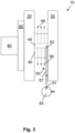
- Fig. 3 shows schematically a second embodiment of a cooling device 10.
- Thermal interface materials 85 are arranged between the component 80 and the first plate 20 in order to further reduce the thermal contact resistance between the component 80 and the plate 20.
- a diffuser 40 is arranged between the plates 20 and 30.
- the diffuser 40 is connected to the fluid source 55 via a line 57.
- the fluid supply 50 in this example only consists of the line 57.
- the fluid flows from the fluid source 55 via the first end 51 in the direction of the arrow 58 to the second end 52 and into the cavity 45 of the diffuser 40. From the cavity 45, the fluid flows into the space formed by the plates 20 and 30 and in which the line 57 is also arranged.
- the arrows 59 show the flow direction of the fluid.
Landscapes
- Engineering & Computer Science (AREA)
- Mechanical Engineering (AREA)
- Physics & Mathematics (AREA)
- Thermal Sciences (AREA)
- Microelectronics & Electronic Packaging (AREA)
- Cooling Or The Like Of Electrical Apparatus (AREA)
- Structures Of Non-Positive Displacement Pumps (AREA)
- Cooling, Air Intake And Gas Exhaust, And Fuel Tank Arrangements In Propulsion Units (AREA)
Description
- Die Erfindung betrifft eine Kühlvorrichtung zur Kühlung eines Bauteils eines Fahrzeugs, insbesondere eines Landfahrzeugs. Weiterhin betrifft die Erfindung ein Fahrzeug und eine Verwendung.
-
US 2002/189874 A1 ,EP 1 592 063 A2 betreffen Kühlvorrichtungen. - Die Kühlung von bestimmten Bauteilen, z.B. Elektronikbauteilen, eines Fahrzeugs kann erforderlich sein, um sowohl akute Schäden durch Überhitzung zu vermeiden, als auch, um die Lebensdauer der Bauteile nicht wegen erhöhter thermischer Belastung zu verkürzen. Dies betrifft auch z.B. Bauteile eines Hochleistungsrechners, sowohl in einem Fahrzeug als auch für stationäre Systeme. Einige dieser Kühlvorrichtungen sind aufwändig herzustellen; manche können keine geringere Temperatur zur Verfügung stellen als die Temperatur der Umgebung.
- Es ist Aufgabe der Erfindung, eine verbesserte Kühlvorrichtung anzugeben.
- Diese Aufgabe wird durch den Gegenstand der unabhängigen Patentansprüche gelöst. Weiterbildungen der Erfindung ergeben sich aus den Unteransprüchen und der folgenden Beschreibung.
- Gemäß einem ersten Aspekt der Erfindung ist eine Kühlvorrichtung zur Kühlung eines Bauteils eines Fahrzeugs angegeben, die eine erste, wärmeleitfähige Platte aufweist, die dem Bauteil benachbart ist. Derartige Bauteile können beispielsweise Elektronikbauteile oder Elektronikkomponenten wie Steuerungsrechner, Dachantennen, Frontkameras und eine Vielzahl weiterer Module oder Komponenten sein. Es kann ein einzelnes Bauteil oder mehrere Bauteile der ersten Platte benachbart sein. Das Bauteil und die erste, wärmeleitfähige Platte sind in einer solchen Weise benachbart, dass Wärmeenergie zwischen dem Bauteil und der Platte ausgetauscht werden kann. Insbesondere kann ein geringer thermischer Widerstand zwischen diesen Elementen vorgesehen sein. Da die Platte wärmeleitfähig ist, kann die Wärmeenergie über die Platte weitergegeben werden. In einer Ausführungsform kann der Übergangswiderstand zwischen dem Bauteil und der Platte durch bestimmte Maßnahmen, z.B. durch eine Wärmeleitpaste, reduziert sein.
- Bei dem Fahrzeug handelt es sich beispielsweise um ein Kraftfahrzeug, wie Auto, Bus oder Lastkraftwagen, oder aber auch um ein Schienenfahrzeug, ein Schiff, ein Luftfahrzeug, wie Helikopter oder Flugzeug.
- Die Kühlvorrichtung weist weiterhin eine zweite Platte auf, die im Wesentlichen parallel zu der ersten Platte angeordnet ist. Die zweite Platte kann ebenfalls wärmeleitfähig sein. Die zweite Platte kann auch aus einem Teil des Fahrzeugs bestehen, z.B. aus einen Abschnitt eines Fahrzeugdachs.
- Die zweite Platte kann in einer Ausführungsform wärmeisolierend sein. Dies kann dann sinnvoll sein, wenn die zweite Platte in der Nähe eines heißen Teils des Fahrzeugs, z.B. in der Nähe des Motors angeordnet ist. Es ist auch nicht erforderlich, dass die zweite Platte exakt parallel zu der ersten Platte angeordnet ist; vielmehr soll durch diese Anordnung eine gute Ableitung des Fluids, das zur Kühlung geeignet ist, gewährleistet sein. Es können auch Kanäle gebildet werden, oder die Ableitung des Fluids kann mittels Leitblechen gesteuert werden.
- Ferner weist die Kühlvorrichtung einen Diffusor auf, der zwischen der ersten Platte und der zweiten Platte angeordnet ist. Der Diffusor ist zum einen durchlässig für das Fluid, insbesondere in mehreren Richtungen durchlässig. Zum andern setzt es dem Fluid einen vordefinierten Widerstand entgegen.
- Die Kühlvorrichtung weist außerdem eine Fluidzuführung auf, die eingerichtet ist, an einem ersten Ende mit einer Fluidquelle verbunden zu werden, und die an einem zweiten Ende mit dem Diffusor in einer solchen Weise verbunden ist, dass ein Fluid von der Fluidquelle von innen nach außen durch den Diffusor strömen kann. Die Fluidquelle, die an dem ersten Ende der Fluidzuführung angeordnet ist, liefert eine Fluidströmung. Die Fluidzuführung ist an dem zweiten Ende mit dem Diffusor verbunden, beispielsweise mit der Mitte des Diffusors. Weil der Diffusor dem Fluid einen vordefinierten Widerstand entgegensetzt, entsteht an dem zweiten Ende der Fluidzuführung ein Überdruck. Durch den Diffusor wird das Fluid gewissermaßen zwangsweise expandiert und das Fluid dadurch abgekühlt (Joule-Thomson-Effekt). Die Kühlvorrichtung stellt daher eine geringere Temperatur zur Verfügung als die Temperatur der Umgebung. Durch die im Wesentlichen parallele Anordnung von der ersten Platte und der zweiten Platte strömt das Fluid über die erste, wärmeleitfähige Platte und sorgt damit für die Verteilung der Wärmeenergie, weg von der ersten Platte und damit dem Bauteil, das der ersten Platte benachbart ist. Gerade die Kombination von Fluidexpansion und Strömung sorgt für eine effiziente Kühlung von Bauteilen.
- Erfindungsgemäß weist der Diffusor einen mittig angeordneten Hohlraum auf, an welchen die Fluidzuführung angeschlossen ist. Der mittig angeordnete Hohlraum ist nicht notwendigerweise koaxial zu den Rändern des Diffusors angeordnet; der Hohlraum kann in einer Ausführungsform auch exzentrisch angeordnet sein. Der Hohlraum kann als durchgängige Passage ausgebildet sein, er kann als Sackloch oder als Höhlung ausgebildet sein. Der Vorteil eines Hohlraums besteht darin, dass sich damit die Diffusionsrichtungen des Fluids besser bestimmen lassen als das bei einer einfachen Einleitung der Fluidzuführung in den Diffusor der Fall ist. Darüber hinaus können in einer Ausführungsform die Wandungen des Hohlraums zur weiteren Festlegung der Diffusionseigenschaften bearbeitet sein, z.B. eine bestimmte Oberflächengestaltung, etwa eine Riffelung, aufweisen oder, zumindest teilweise, mit bestimmten Materialen, z.B. Gold, veredelt, um beispielsweise die Korrosionsfestigkeit und/oder die Wärmeleitung weiter zu verbessern.
- In einer Ausführungsform weist die Fluidzuführung eine Passage auf, welche durch die zweite Platte zu dem Diffusor führt und die an einem ersten Ende an den Diffusor und an einem zweiten Ende über eine Leitung mit der Fluidquelle verbunden ist. Damit wird das Fluid durch die Passage in der zweiten Platte zugeführt. Dies eignet sich besonders für Ausführungen, bei denen die Kühlvorrichtung sehr gut seitlich zugänglich ist.
- In einer Ausführungsform weist die Fluidzuführung eine Leitung auf, welche direkt an den Diffusor angeschlossen ist. Die Leitung verläuft also, zumindest teilweise, durch die Beabstandung zwischen der ersten und der zweiten Platte, welche auch zur Ableitung eines Fluids dient.
- In einer Ausführungsform ist der Diffusor mit mindestens einer der Platten form-, kraft- und/oder stoffschlüssig verbunden. Dabei kann der Diffusor zumindest an eine der Platten geklebt, geschweißt, gelötet, geschraubt, genietet sein oder auch zwischen die Platten eingeklemmt. Die Verbindung zur ersten Platte kann wärmeleitfähig sein, z.B. mittels Wärmeleitkleber. In einer Ausführungsform kann der Diffusor mit der ersten Platte als einstückiges Element gestaltet sein. In einer Ausführungsform sind der Diffusor und die erste Platte als einstückiges Element ausgestaltet, wobei in dem Element ein Übergang, insbesondere ein nahtloser Übergang, zwischen dem Material des Diffusors und dem Material der ersten Platte realisiert ist. Diese Ausführungsform hat den Vorteil, dass diese besonders kostengünstig realisiert werden kann; außerdem weist die Ausführungsform besonders gute Wärmeleiteigenschaften auf. In einer Ausführungsform ist die erste Platte als Heat-Pipe ausgeführt. Dies verbessert den Wärmetransport der Heat-Pipe weiter.
- wobei der Diffusor (40) mit mindestens einer der Platten (20, 30) form-, kraft- und/oder stoffschlüssig verbunden ist oder der Diffusor (40) und die erste Platte (20) als einstückiges Element ausgestaltet sind, wobei in dem Element ein Übergang, insbesondere ein nahtloser Übergang, zwischen dem Material des Diffusors (40) und dem Material der ersten Platte (20) realisiert ist.
- In einer Ausführungsform ist der Diffusor ein Sinterfilter. Der Diffusor kann eine Vielzahl von dünnen Stegen, etwa in Form einer Bürste, oder von Zylindern, oder auch ein Labyrinth aufweisen. Die Stege bzw. Zylinder können Durchmesser von kleiner 100 µm, insbesondere von kleiner 10 µm, aufweisen.
- In einer Ausführungsform ist die Fluidquelle ein Kompressor, insbesondere ein Sitz-Kompressor. Ein Sitz-Kompressor hat den Vorteil, dass dieser bereits für die Verwendung in Fahrzeugen ausgelegt ist, z.B. hinsichtlich Betriebsspannung oder Temperaturbereich.
- In einer Ausführungsform ist die Fluidquelle in einem kühleren Teil des Fahrzeugs als das Bauteil angeordnet. Die Fluidquelle kann beispielsweise näher am Boden oder im Bereich der Zwangsentlüftung des Fahrzeugs angeordnet sein. Die Platzierung des Bauteils ist dagegen oftmals durch seine Funktionalität vorbestimmt; so wird beispielsweise ein Motorsteuergerät in der Nähe des (heißen) Motors platziert sein, oder eine Dachantenne ist im Bereich des (potentiell heißen) Fahrzeugdachs platziert.
- In einer Ausführungsform weist die Fluidquelle einen Überdruck zwischen 0,05 und 1,0 bar, insbesondere zwischen 0,1 und 0,3 bar, auf. Ein Überdruck in diesem Bereich ist technisch recht einfach und kostengünstig beherrschbar, und es können Standardleitungen verwendet werden.
- In einer Ausführungsform ist das Fluid ein Gas, insbesondere Luft. Für spezielle Verwendungen können auch andere Gase oder auch Flüssigkeiten verwendet werden.
- In einer Ausführungsform weist die erste Platte eine Wärmeleitfähigkeit von größer 50 W / (m · K), insbesondere von größer 200 W / (m · K), auf. Eine Wärmeleitfähigkeit in diesem Bereich unterstützt die Kühlung auf effiziente Weise. Materialien können z.B. Aluminium, Aluminium-Legierungen oder Kupfer sein. Die erste Platte kann auch eine Platine für Elektronikbaugruppen sein, die besonders wärmeleitfähig gestaltet ist; dies kann z.B. mittels Feldern von Vias (Durchkontaktierungen) realisiert sein.
- In einer Ausführungsform sind zwischen dem Bauteil und der ersten Platte thermische Interface-Materialien angeordnet. Diese Materialien werden auch als "Thermal Interface Material" (TIM) bezeichnet. Die Materialien umfassen z.B. Wärmeleitpasten, wärmeleitfähige Kleber oder bestimmte Sorten von Silizium-Pads.
- Ein weiterer Aspekt der Erfindung betrifft eine Verwendung einer Kühlvorrichtung wie oben und im Folgenden beschrieben zur Kühlung einer Automobilelektronik, von Kameramodulen, z.B. im Bereich der Frontscheibe von Fahrzeugen, oder von Rechnern, insbesondere von Hochleistungsrechnern.
- Gemäß einem weiteren Aspekt der Erfindung ist ein Fahrzeug mit einer oben beschriebenen Kühlvorrichtung angegeben.
- Zur weiteren Verdeutlichung wird die Erfindung anhand von in den Figuren abgebildeten Ausführungsformen beschrieben. Diese Ausführungsformen sind nur als Beispiel, nicht aber als Einschränkung zu verstehen.
-
Fig. 1 zeigt schematisch ein Fahrzeug mit einer Kühlvorrichtung; -
Fig. 2 zeigt schematisch eine erste Ausführungsform einer Kühlvorrichtung; -
Fig. 3 zeigt schematisch eine zweite Ausführungsform einer Kühlvorrichtung. -
Fig. 1 zeigt ein Fahrzeug 90, in dessen Dachbereich 92 eine Kühlvorrichtung 10 angeordnet ist. Die Kühlvorrichtung 10 kann beispielsweise zur Kühlung einer Autoantenne 94 eingesetzt werden. Dabei ist die Autoantenne 94 oberhalb des Dachs angeordnet, die Kühlvorrichtung 10 unterhalb des Dachs. Im Bereich des Hecks des Fahrzeugs 90 ist ein Kompressor 55 angeordnet, der als Fluidquelle 55 für die Kühlvorrichtung 10 dient. Die Anordnung des Kompressors 55 an dieser Stelle kann dadurch motiviert sein, dass an dieser Stelle die Temperatur in vielen Fällen niedriger sein kann als in dem Dachbereich 92. In anderen Ausführungsformen - oder zur Kühlung anderer Bauteile - kann der Kompressor 55 auch nahe an der Kühlvorrichtung 10 angeordnet sein. Der Kompressor 55 ist mit der Kühlvorrichtung 10 über eine Leitung 57 verbunden. Da der Druck, den der Kompressor 55 erzeugt, relativ niedrig ist, sind die Anforderungen an die Druckbeständigkeit der Leitung 57 recht gering. - Bei der Ausführungsform von
Fig. 2 wird ein Bauteil 80 mittels der Kühlvorrichtung 10 gekühlt. Benachbart zu dem Bauteil 80 ist eine erste, wärmeleitfähige Platte 20 angeordnet, so dass Wärmeenergie zwischen dem Bauteil und der Platte ausgetauscht werden kann. Die wärmeleitfähige Platte 20 kann die Wärmeenergie weitergeben, sowohl innerhalb der Platte 20 als auch durch die Platte 20 hindurch. Benachbart zu der ersten Platte 20 ist ein Diffusor 40 und, daran anschließend, ist eine zweite Platte 30 angeordnet. Bei einer Ausführungsform, wie sie inFig. 1 skizziert ist, kann die zweite Platte 30 auch durch einen Teil des Dachbereichs 92 des Fahrzeugs 90 oder durch einen Teil einer Autoantenne 94 gebildet sein. - Bei der gezeigten Ausführungsform wird eine Fluidquelle 55 für die Kühlvorrichtung 10 eingesetzt. An die Fluidquelle 55 ist eine Fluidzuführung 50 angeschlossen. Bei diesem Ausführungsbeispiel besteht die Fluidzuführung 50 aus einer Leitung 57, die mit einem ersten Ende 51 an die Fluidquelle 55 angeschlossen ist. Die Fluidzuführung 50 weist weiterhin eine Passage 35 auf, die mit der Leitung 57 verbunden ist. Die Passage 35 führt durch die zweite Platte 30 zu dem Diffusor 40 und bildet, am Ende der Passage 35, das zweite Ende 52 der Fluidzuführung 50. Das Fluid strömt also von der Fluidquelle 55 in Richtung des Pfeils 58 durch die Leitung 57 und durch die Passage 35 in den Hohlraum 45 des Diffusors 40. Vom dem Hohlraum 45 strömt das Fluid in den Raum, der durch die Platten 20 und 30 gebildet wird. Die Pfeile 59 zeigen die Strömungsrichtung des Fluids. Das Fluid strömt dabei über die erste Platte 20 und verbessert dadurch die Kühlung des Bauteils 80.
-
Fig. 3 zeigt schematisch eine zweite Ausführungsform einer Kühlvorrichtung 10. Dabei sind zwischen dem Bauteil 80 und der ersten Platte 20 thermische Interface-Materialien 85 angeordnet, um den thermischen Übergangswiderstand zwischen dem Bauteil 80 und der Platte 20 weiter zu reduzieren. Zwischen den Platten 20 und 30 ist ein Diffusor 40 angeordnet. Der Diffusor 40 ist über eine Leitung 57 mit der Fluidquelle 55 verbunden. Die Fluidzuführung 50 besteht in diesem Beispiel nur aus der Leitung 57. Das Fluid strömt von der Fluidquelle 55 über das erste Ende 51 in Richtung des Pfeils 58 zu dem zweiten Ende 52 und in den Hohlraum 45 des Diffusors 40. Von dem Hohlraum 45 strömt das Fluid in den Raum, der durch die Platten 20 und 30 gebildet wird und in dem auch die Leitung 57 angeordnet ist. Die Pfeile 59 zeigen die Strömungsrichtung des Fluids. -
- 10
- Kühlvorrichtung
- 20
- erste, wärmeleitfähige Platte
- 30
- zweite Platte
- 35
- Passage
- 40
- Diffusor
- 45
- Hohlraum
- 50
- Fluidzuführung
- 51, 52
- erstes bzw. zweites Ende der Fluidzuführung
- 55
- Fluidquelle, Kompressor
- 57
- Leitung
- 58
- Pfeil (Strömungsrichtung in der Leitung)
- 59
- Pfeile (Strömungsrichtung aus dem Diffusor)
- 80
- Bauteil
- 85
- thermische Interface-Materialien
- 90
- Fahrzeug
- 92, 94
- Dachbereich bzw. Autoantenne des Fahrzeugs
Claims (13)
- Kühlvorrichtung (10) zur Kühlung eines Bauteils (80) eines Fahrzeugs (90), aufweisend:eine erste, wärmeleitfähige Platte (20), die dem Bauteil (80) benachbart ist,eine zweite Platte (30), die im Wesentlichen parallel zu der ersten Platte (20) angeordnet ist,einen Diffusor (40), der zwischen der ersten Platte (20) und der zweiten Platte (30) angeordnet ist, undeine Fluidzuführung (50), die eingerichtet ist, an einem ersten Ende (51) mit einer Fluidquelle (55) verbunden zu werden, und die an einem zweiten Ende (52) mit dem Diffusor (40) in einer solchen Weise verbunden ist, dass ein Fluid von der Fluidquelle (55) von innen nach außen durch den Diffusor (40) strömen kann,wobei der Diffusor (40) einen mittig angeordneten Hohlraum (45) aufweist, an welchen die Fluidzuführung (50) angeschlossen ist.
- Kühlvorrichtung (10) nach Anspruch 1,
wobei die Fluidzuführung (50) eine Passage (35) aufweist, welche durch die zweite Platte (30) zu dem Diffusor (40) führt und die an einem ersten Ende an den Diffusor (40) und an einem zweiten Ende über eine Leitung (57) mit der Fluidquelle (55) verbunden ist. - Kühlvorrichtung (10) nach Anspruch 1 oder 2,
wobei die Fluidzuführung (50) eine Leitung (57) aufweist, welche direkt an den Diffusor (40) angeschlossen ist. - Kühlvorrichtung (10) nach einem der vorhergehenden Ansprüche,wobei der Diffusor (40) mit mindestens einer der Platten (20, 30) form-, kraft- und/oder stoffschlüssig verbunden ist oderder Diffusor (40) und die erste Platte (20) als einstückiges Element ausgestaltet sind, wobei in dem Element ein Übergang, insbesondere ein nahtloser Übergang, zwischen dem Material des Diffusors (40) und dem Material der ersten Platte (20) realisiert ist.
- Kühlvorrichtung (10) nach einem der vorhergehenden Ansprüche,
wobei der Diffusor (40) ein Sinterfilter ist, eine Vielzahl von dünnen Stegen oder ein Labyrinth aufweist. - Kühlvorrichtung (10) nach einem der vorhergehenden Ansprüche,
wobei die Fluidquelle (55) ein Kompressor, insbesondere ein Sitz-Kompressor, ist. - Kühlvorrichtung (10) nach einem der vorhergehenden Ansprüche,
wobei die Fluidquelle (55) in einem kühleren Teil des Fahrzeugs als das Bauteil (80) angeordnet ist. - Kühlvorrichtung (10) nach einem der vorhergehenden Ansprüche,
wobei die Fluidquelle (55) einen Überdruck zwischen 0,05 und 1,0 bar, insbesondere zwischen 0,1 und 0,3 bar, aufweist. - Kühlvorrichtung (10) nach einem der vorhergehenden Ansprüche,
wobei das Fluid ein Gas, insbesondere Luft, ist. - Kühlvorrichtung (10) nach einem der vorhergehenden Ansprüche,
wobei die erste Platte (20) eine Wärmeleitfähigkeit von größer 50 W / (m · K), insbesondere von größer 200 W / (m · K), aufweist. - Kühlvorrichtung (10) nach einem der vorhergehenden Ansprüche,
wobei zwischen dem Bauteil (80) und der ersten Platte (20) thermische Interface-Materialien angeordnet sind. - Verwendung einer Kühlvorrichtung (10) nach einem der Ansprüche 1 bis 10 zur Kühlung einer Automobilelektronik, von Kameramodulen, z.B. im Bereich der Frontscheibe, oder von Rechnern, insbesondere Hochleistungsrechnern.
- Fahrzeug mit einer Kühlvorrichtung (10) nach einem der Ansprüche 1 bis 10.
Applications Claiming Priority (2)
| Application Number | Priority Date | Filing Date | Title |
|---|---|---|---|
| DE102018214539.3A DE102018214539B3 (de) | 2018-08-28 | 2018-08-28 | Kühlvorrichtung für Bauteile in einem Fahrzeug |
| PCT/EP2019/070983 WO2020043432A1 (de) | 2018-08-28 | 2019-08-05 | Kühlvorrichtung für bauteile in einem fahrzeug |
Publications (2)
| Publication Number | Publication Date |
|---|---|
| EP3844030A1 EP3844030A1 (de) | 2021-07-07 |
| EP3844030B1 true EP3844030B1 (de) | 2024-10-09 |
Family
ID=67667811
Family Applications (1)
| Application Number | Title | Priority Date | Filing Date |
|---|---|---|---|
| EP19755837.2A Active EP3844030B1 (de) | 2018-08-28 | 2019-08-05 | Kühlvorrichtung für bauteile in einem fahrzeug |
Country Status (3)
| Country | Link |
|---|---|
| EP (1) | EP3844030B1 (de) |
| DE (1) | DE102018214539B3 (de) |
| WO (1) | WO2020043432A1 (de) |
Families Citing this family (1)
| Publication number | Priority date | Publication date | Assignee | Title |
|---|---|---|---|---|
| FR3114280B1 (fr) * | 2020-09-24 | 2022-08-05 | Psa Automobiles Sa | Refroidissement d’un boitier de connectivité par un liquide lave-glace |
Family Cites Families (12)
| Publication number | Priority date | Publication date | Assignee | Title |
|---|---|---|---|---|
| DE3036098C2 (de) | 1980-09-25 | 1983-12-08 | H. Peter Dipl.-Ing. 5400 Koblenz Nardin | Bordcomputer für Verkehrsmittel, insbesondere Kraftfahrzeuge |
| DE3151301A1 (de) | 1981-12-24 | 1983-07-07 | Brown, Boveri & Cie Ag, 6800 Mannheim | "schrank zur aufnahme von elektrischen bauelementen" |
| JPH098486A (ja) * | 1995-06-16 | 1997-01-10 | Zojirushi Corp | 実装部品の冷却構造 |
| DE19645636C1 (de) * | 1996-11-06 | 1998-03-12 | Telefunken Microelectron | Leistungsmodul zur Ansteuerung von Elektromotoren |
| GB2343161A (en) * | 1998-10-28 | 2000-05-03 | Rover Group | Cooling of electrical equipment |
| AU2001264795A1 (en) | 2000-05-22 | 2001-12-03 | Materials Innovation Inc. | Porous heat sink for forced convective flow and method of making therefore |
| DE10102869A1 (de) | 2001-01-23 | 2002-08-14 | Siemens Ag | Vorrichtung und Verfahren zur Kühlung von temperaturkritischen Bauteilen |
| JP4706133B2 (ja) * | 2001-06-15 | 2011-06-22 | 株式会社豊田自動織機 | 産業車両における制御装置の冷却構造及びカウンタバランス型フォークリフトトラック |
| US6898082B2 (en) * | 2002-05-10 | 2005-05-24 | Serguei V. Dessiatoun | Enhanced heat transfer structure with heat transfer members of variable density |
| DE102004021122B4 (de) * | 2004-04-29 | 2007-10-11 | Semikron Elektronik Gmbh & Co. Kg | Anordnung in Druckkontaktierung mit einem Leistungshalbleitermodul |
| CN103167780B (zh) * | 2011-12-16 | 2016-06-08 | 台达电子企业管理(上海)有限公司 | 功率模块用复合式散热器组件 |
| DE102017002601A1 (de) | 2017-03-17 | 2018-09-20 | Man Truck & Bus Ag | Kühlvorrichtung für elektronisches Steuergerät |
-
2018
- 2018-08-28 DE DE102018214539.3A patent/DE102018214539B3/de active Active
-
2019
- 2019-08-05 WO PCT/EP2019/070983 patent/WO2020043432A1/de not_active Ceased
- 2019-08-05 EP EP19755837.2A patent/EP3844030B1/de active Active
Also Published As
| Publication number | Publication date |
|---|---|
| DE102018214539B3 (de) | 2019-12-19 |
| EP3844030A1 (de) | 2021-07-07 |
| WO2020043432A1 (de) | 2020-03-05 |
Similar Documents
| Publication | Publication Date | Title |
|---|---|---|
| EP3376839B1 (de) | Kühlvorrichtung für elektronisches steuergerät | |
| DE112022004158T5 (de) | Halbleitervorrichtung | |
| DE102022205647A1 (de) | Kühlanordnung, Steuereinrichtung, Kühlkörper sowie Herstellungsverfahren | |
| EP1911335B1 (de) | Kühlsystem für elektronikgehäuse | |
| EP3844030B1 (de) | Kühlvorrichtung für bauteile in einem fahrzeug | |
| DE102018218049B4 (de) | Kühlmodul für ein Fahrzeug-Steuergerät, Fahrzeug-Steuergerät mit einem Kühlmodul und Verfahren zur Wasserkühlung eines Fahrzeug-Steuergeräts | |
| DE102022213806A1 (de) | Kühlanordnung, Steuereinrichtung, Steuereinrichtungssystem und Herstellungsverfahren | |
| DE102021207284A1 (de) | Pulswechselrichter mit zentraler Kühlvorrichtung | |
| DE102018210141A1 (de) | Diodenlaseranordnung und Verfahren zur Herstellung einer Diodenlaseranordnung | |
| EP1492990A2 (de) | Wärmetauscher und kühlsystem | |
| DE102006040187A1 (de) | Kühlvorrichtung, Kühlsystem und Kühlverfahren zur Kühlung von Bauelementen einer Leistungselektronik | |
| DE102018118925A1 (de) | Lüfter mit Kühlkörper | |
| DE10313355B4 (de) | Kühlanordnung | |
| EP4409632A1 (de) | Kühler zum kühlen einer leistungselektronik | |
| EP1924132A1 (de) | Kühler | |
| DE102020126771A1 (de) | Leistungselektronikvorrichtung sowie Kraftfahrzeug mit einer Leistungselektronikvorrichtung | |
| EP0139973A2 (de) | Anordnung zur Wärmeabführung bei Schichtschaltungen | |
| DE102019134118B4 (de) | Fahrzeugelektronikbaugruppenvorrichtung mit kombinierbaren Elektronikbaugruppen | |
| DE102012223087A1 (de) | Vorrichtung zur Entnahme eines gefrierfähigen Fluids aus einem Fluidtank sowie Fluidtank | |
| DE102024101832A1 (de) | Elektrische Heizvorrichtung | |
| DE102023210481A1 (de) | Kühlvorrichtung zum Kühlen von zumindest einer Leiterplatte | |
| DE102024111436A1 (de) | Fahrzeugmodul mit einem Gehäuse und einer in dem Gehäuse angeordneten Elektronikeinheit sowie Fertigungsverfahren für ein Fahrzeugmodul | |
| DE102024107946A1 (de) | Kühlvorrichtung mit zwei Kühlplatten zum Kühlen eines elektronischen Bauelementes eines Kraftfahrzeuges, Elektronische Baugruppe und Kraftfahrzeug | |
| EP3125646B1 (de) | Elektrische heizvorrichtung | |
| DE102024203038A1 (de) | Adapterplatte zur Befestigung eines Gehäuses und Steuergerät mit einer Adapterplatte |
Legal Events
| Date | Code | Title | Description |
|---|---|---|---|
| STAA | Information on the status of an ep patent application or granted ep patent |
Free format text: STATUS: UNKNOWN |
|
| STAA | Information on the status of an ep patent application or granted ep patent |
Free format text: STATUS: THE INTERNATIONAL PUBLICATION HAS BEEN MADE |
|
| STAA | Information on the status of an ep patent application or granted ep patent |
Free format text: STATUS: REQUEST FOR EXAMINATION WAS MADE |
|
| PUAI | Public reference made under article 153(3) epc to a published international application that has entered the european phase |
Free format text: ORIGINAL CODE: 0009012 |
|
| 17P | Request for examination filed |
Effective date: 20210329 |
|
| AK | Designated contracting states |
Kind code of ref document: A1 Designated state(s): AL AT BE BG CH CY CZ DE DK EE ES FI FR GB GR HR HU IE IS IT LI LT LU LV MC MK MT NL NO PL PT RO RS SE SI SK SM TR |
|
| DAV | Request for validation of the european patent (deleted) | ||
| DAX | Request for extension of the european patent (deleted) | ||
| RAP1 | Party data changed (applicant data changed or rights of an application transferred) |
Owner name: CONTINENTAL AUTOMOTIVE TECHNOLOGIES GMBH |
|
| RAP3 | Party data changed (applicant data changed or rights of an application transferred) |
Owner name: CONTINENTAL AUTOMOTIVE TECHNOLOGIES GMBH |
|
| GRAP | Despatch of communication of intention to grant a patent |
Free format text: ORIGINAL CODE: EPIDOSNIGR1 |
|
| STAA | Information on the status of an ep patent application or granted ep patent |
Free format text: STATUS: GRANT OF PATENT IS INTENDED |
|
| INTG | Intention to grant announced |
Effective date: 20240606 |
|
| GRAS | Grant fee paid |
Free format text: ORIGINAL CODE: EPIDOSNIGR3 |
|
| GRAA | (expected) grant |
Free format text: ORIGINAL CODE: 0009210 |
|
| STAA | Information on the status of an ep patent application or granted ep patent |
Free format text: STATUS: THE PATENT HAS BEEN GRANTED |
|
| AK | Designated contracting states |
Kind code of ref document: B1 Designated state(s): AL AT BE BG CH CY CZ DE DK EE ES FI FR GB GR HR HU IE IS IT LI LT LU LV MC MK MT NL NO PL PT RO RS SE SI SK SM TR |
|
| REG | Reference to a national code |
Ref country code: CH Ref legal event code: EP |
|
| REG | Reference to a national code |
Ref country code: DE Ref legal event code: R096 Ref document number: 502019012278 Country of ref document: DE |
|
| REG | Reference to a national code |
Ref country code: IE Ref legal event code: FG4D Free format text: LANGUAGE OF EP DOCUMENT: GERMAN |
|
| REG | Reference to a national code |
Ref country code: LT Ref legal event code: MG9D |
|
| REG | Reference to a national code |
Ref country code: NL Ref legal event code: MP Effective date: 20241009 |
|
| PG25 | Lapsed in a contracting state [announced via postgrant information from national office to epo] |
Ref country code: NL Free format text: LAPSE BECAUSE OF FAILURE TO SUBMIT A TRANSLATION OF THE DESCRIPTION OR TO PAY THE FEE WITHIN THE PRESCRIBED TIME-LIMIT Effective date: 20241009 |
|
| PG25 | Lapsed in a contracting state [announced via postgrant information from national office to epo] |
Ref country code: NL Free format text: LAPSE BECAUSE OF FAILURE TO SUBMIT A TRANSLATION OF THE DESCRIPTION OR TO PAY THE FEE WITHIN THE PRESCRIBED TIME-LIMIT Effective date: 20241009 |
|
| PG25 | Lapsed in a contracting state [announced via postgrant information from national office to epo] |
Ref country code: IS Free format text: LAPSE BECAUSE OF FAILURE TO SUBMIT A TRANSLATION OF THE DESCRIPTION OR TO PAY THE FEE WITHIN THE PRESCRIBED TIME-LIMIT Effective date: 20250209 Ref country code: PT Free format text: LAPSE BECAUSE OF FAILURE TO SUBMIT A TRANSLATION OF THE DESCRIPTION OR TO PAY THE FEE WITHIN THE PRESCRIBED TIME-LIMIT Effective date: 20250210 Ref country code: HR Free format text: LAPSE BECAUSE OF FAILURE TO SUBMIT A TRANSLATION OF THE DESCRIPTION OR TO PAY THE FEE WITHIN THE PRESCRIBED TIME-LIMIT Effective date: 20241009 |
|
| PG25 | Lapsed in a contracting state [announced via postgrant information from national office to epo] |
Ref country code: FI Free format text: LAPSE BECAUSE OF FAILURE TO SUBMIT A TRANSLATION OF THE DESCRIPTION OR TO PAY THE FEE WITHIN THE PRESCRIBED TIME-LIMIT Effective date: 20241009 |
|
| PG25 | Lapsed in a contracting state [announced via postgrant information from national office to epo] |
Ref country code: BG Free format text: LAPSE BECAUSE OF FAILURE TO SUBMIT A TRANSLATION OF THE DESCRIPTION OR TO PAY THE FEE WITHIN THE PRESCRIBED TIME-LIMIT Effective date: 20241009 |
|
| PG25 | Lapsed in a contracting state [announced via postgrant information from national office to epo] |
Ref country code: ES Free format text: LAPSE BECAUSE OF FAILURE TO SUBMIT A TRANSLATION OF THE DESCRIPTION OR TO PAY THE FEE WITHIN THE PRESCRIBED TIME-LIMIT Effective date: 20241009 |
|
| PG25 | Lapsed in a contracting state [announced via postgrant information from national office to epo] |
Ref country code: NO Free format text: LAPSE BECAUSE OF FAILURE TO SUBMIT A TRANSLATION OF THE DESCRIPTION OR TO PAY THE FEE WITHIN THE PRESCRIBED TIME-LIMIT Effective date: 20250109 |
|
| PG25 | Lapsed in a contracting state [announced via postgrant information from national office to epo] |
Ref country code: LV Free format text: LAPSE BECAUSE OF FAILURE TO SUBMIT A TRANSLATION OF THE DESCRIPTION OR TO PAY THE FEE WITHIN THE PRESCRIBED TIME-LIMIT Effective date: 20241009 Ref country code: GR Free format text: LAPSE BECAUSE OF FAILURE TO SUBMIT A TRANSLATION OF THE DESCRIPTION OR TO PAY THE FEE WITHIN THE PRESCRIBED TIME-LIMIT Effective date: 20250110 |
|
| PG25 | Lapsed in a contracting state [announced via postgrant information from national office to epo] |
Ref country code: PL Free format text: LAPSE BECAUSE OF FAILURE TO SUBMIT A TRANSLATION OF THE DESCRIPTION OR TO PAY THE FEE WITHIN THE PRESCRIBED TIME-LIMIT Effective date: 20241009 |
|
| PG25 | Lapsed in a contracting state [announced via postgrant information from national office to epo] |
Ref country code: RS Free format text: LAPSE BECAUSE OF FAILURE TO SUBMIT A TRANSLATION OF THE DESCRIPTION OR TO PAY THE FEE WITHIN THE PRESCRIBED TIME-LIMIT Effective date: 20250109 |
|
| PG25 | Lapsed in a contracting state [announced via postgrant information from national office to epo] |
Ref country code: SM Free format text: LAPSE BECAUSE OF FAILURE TO SUBMIT A TRANSLATION OF THE DESCRIPTION OR TO PAY THE FEE WITHIN THE PRESCRIBED TIME-LIMIT Effective date: 20241009 |
|
| PG25 | Lapsed in a contracting state [announced via postgrant information from national office to epo] |
Ref country code: DK Free format text: LAPSE BECAUSE OF FAILURE TO SUBMIT A TRANSLATION OF THE DESCRIPTION OR TO PAY THE FEE WITHIN THE PRESCRIBED TIME-LIMIT Effective date: 20241009 |
|
| REG | Reference to a national code |
Ref country code: DE Ref legal event code: R097 Ref document number: 502019012278 Country of ref document: DE |
|
| PG25 | Lapsed in a contracting state [announced via postgrant information from national office to epo] |
Ref country code: EE Free format text: LAPSE BECAUSE OF FAILURE TO SUBMIT A TRANSLATION OF THE DESCRIPTION OR TO PAY THE FEE WITHIN THE PRESCRIBED TIME-LIMIT Effective date: 20241009 |
|
| PG25 | Lapsed in a contracting state [announced via postgrant information from national office to epo] |
Ref country code: RO Free format text: LAPSE BECAUSE OF FAILURE TO SUBMIT A TRANSLATION OF THE DESCRIPTION OR TO PAY THE FEE WITHIN THE PRESCRIBED TIME-LIMIT Effective date: 20241009 |
|
| PG25 | Lapsed in a contracting state [announced via postgrant information from national office to epo] |
Ref country code: SK Free format text: LAPSE BECAUSE OF FAILURE TO SUBMIT A TRANSLATION OF THE DESCRIPTION OR TO PAY THE FEE WITHIN THE PRESCRIBED TIME-LIMIT Effective date: 20241009 |
|
| PG25 | Lapsed in a contracting state [announced via postgrant information from national office to epo] |
Ref country code: CZ Free format text: LAPSE BECAUSE OF FAILURE TO SUBMIT A TRANSLATION OF THE DESCRIPTION OR TO PAY THE FEE WITHIN THE PRESCRIBED TIME-LIMIT Effective date: 20241009 |
|
| PLBE | No opposition filed within time limit |
Free format text: ORIGINAL CODE: 0009261 |
|
| STAA | Information on the status of an ep patent application or granted ep patent |
Free format text: STATUS: NO OPPOSITION FILED WITHIN TIME LIMIT |
|
| PG25 | Lapsed in a contracting state [announced via postgrant information from national office to epo] |
Ref country code: SE Free format text: LAPSE BECAUSE OF FAILURE TO SUBMIT A TRANSLATION OF THE DESCRIPTION OR TO PAY THE FEE WITHIN THE PRESCRIBED TIME-LIMIT Effective date: 20241009 |
|
| 26N | No opposition filed |
Effective date: 20250710 |
|
| PGFP | Annual fee paid to national office [announced via postgrant information from national office to epo] |
Ref country code: DE Payment date: 20250831 Year of fee payment: 7 |
|
| PGFP | Annual fee paid to national office [announced via postgrant information from national office to epo] |
Ref country code: IT Payment date: 20250825 Year of fee payment: 7 |
|
| PGFP | Annual fee paid to national office [announced via postgrant information from national office to epo] |
Ref country code: GB Payment date: 20250820 Year of fee payment: 7 |
|
| PGFP | Annual fee paid to national office [announced via postgrant information from national office to epo] |
Ref country code: FR Payment date: 20250828 Year of fee payment: 7 |
|
| REG | Reference to a national code |
Ref country code: DE Ref legal event code: R081 Ref document number: 502019012278 Country of ref document: DE Owner name: AUMOVIO GERMANY GMBH, DE Free format text: FORMER OWNER: CONTINENTAL AUTOMOTIVE TECHNOLOGIES GMBH, 30175 HANNOVER, DE |
|
| REG | Reference to a national code |
Ref country code: CH Ref legal event code: H13 Free format text: ST27 STATUS EVENT CODE: U-0-0-H10-H13 (AS PROVIDED BY THE NATIONAL OFFICE) Effective date: 20260324 |
|
| PG25 | Lapsed in a contracting state [announced via postgrant information from national office to epo] |
Ref country code: MC Free format text: LAPSE BECAUSE OF FAILURE TO SUBMIT A TRANSLATION OF THE DESCRIPTION OR TO PAY THE FEE WITHIN THE PRESCRIBED TIME-LIMIT Effective date: 20241009 |
|
| PG25 | Lapsed in a contracting state [announced via postgrant information from national office to epo] |
Ref country code: LU Free format text: LAPSE BECAUSE OF NON-PAYMENT OF DUE FEES Effective date: 20250805 |
|
| PG25 | Lapsed in a contracting state [announced via postgrant information from national office to epo] |
Ref country code: CH Free format text: LAPSE BECAUSE OF NON-PAYMENT OF DUE FEES Effective date: 20250831 |