EP3843499B1 - Anpassbare antennenvorrichtung - Google Patents
Anpassbare antennenvorrichtung Download PDFInfo
- Publication number
- EP3843499B1 EP3843499B1 EP19864985.7A EP19864985A EP3843499B1 EP 3843499 B1 EP3843499 B1 EP 3843499B1 EP 19864985 A EP19864985 A EP 19864985A EP 3843499 B1 EP3843499 B1 EP 3843499B1
- Authority
- EP
- European Patent Office
- Prior art keywords
- antenna
- signal processing
- unit
- feeding
- feeding network
- Prior art date
- Legal status (The legal status is an assumption and is not a legal conclusion. Google has not performed a legal analysis and makes no representation as to the accuracy of the status listed.)
- Active
Links
Images



Classifications
-
- H—ELECTRICITY
- H01—ELECTRIC ELEMENTS
- H01Q—ANTENNAS, i.e. RADIO AERIALS
- H01Q1/00—Details of, or arrangements associated with, antennas
- H01Q1/50—Structural association of antennas with earthing switches, lead-in devices or lightning protectors
-
- H—ELECTRICITY
- H01—ELECTRIC ELEMENTS
- H01Q—ANTENNAS, i.e. RADIO AERIALS
- H01Q3/00—Arrangements for changing or varying the orientation or the shape of the directional pattern of the waves radiated from an antenna or antenna system
- H01Q3/26—Arrangements for changing or varying the orientation or the shape of the directional pattern of the waves radiated from an antenna or antenna system varying the relative phase or relative amplitude of energisation between two or more active radiating elements; varying the distribution of energy across a radiating aperture
-
- H—ELECTRICITY
- H01—ELECTRIC ELEMENTS
- H01Q—ANTENNAS, i.e. RADIO AERIALS
- H01Q21/00—Antenna arrays or systems
- H01Q21/0006—Particular feeding systems
- H01Q21/0025—Modular arrays
-
- H—ELECTRICITY
- H01—ELECTRIC ELEMENTS
- H01Q—ANTENNAS, i.e. RADIO AERIALS
- H01Q21/00—Antenna arrays or systems
- H01Q21/0006—Particular feeding systems
-
- H—ELECTRICITY
- H01—ELECTRIC ELEMENTS
- H01Q—ANTENNAS, i.e. RADIO AERIALS
- H01Q23/00—Antennas with active circuits or circuit elements integrated within them or attached to them
-
- H—ELECTRICITY
- H01—ELECTRIC ELEMENTS
- H01Q—ANTENNAS, i.e. RADIO AERIALS
- H01Q21/00—Antenna arrays or systems
- H01Q21/06—Arrays of individually energised antenna units similarly polarised and spaced apart
- H01Q21/061—Two dimensional planar arrays
Definitions
- This application relates to the field of communications technologies, and in particular, to an antenna apparatus.
- US2005/0085267 A1 relates to base station arrangements for diversity transmission and reception.
- This application provides an antenna apparatus, to improve adaptability of the antenna apparatus.
- an antenna apparatus is provided.
- a communications system is further provided.
- the communications system includes the antenna apparatus according to any one of claims 1 to 6.
- the radio frequency unit and the antenna are connected by using an integrated signal processing module.
- the signal processing module may be integrated with components such as the filter, the duplexer, and the feeding network. Components for processing signals are integrated by using the signal processing module, to improve an integration degree of the antenna apparatus, thereby achieving a high integration degree.
- the signal processing module uses a pluggable manner to facilitate replacement.
- the antenna includes the spliceable antenna bay. Therefore, the antenna apparatus can use different signal processing modules based on requirements in different scenarios and matching antennas are replaced at the same time. For example, antenna replacement can be implemented by splicing antenna bays. This improves flexibility and adaptability of the antenna apparatus and also facilitates more convenient replacement of the antenna apparatus.
- An antenna apparatus provided in the embodiments of this application is applied to a network device and can adapt to different communication scenarios, featuring flexibility and adaptability.
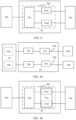
- FIG. 1 is a schematic structural diagram of an antenna apparatus 100 according to an embodiment of this application.
- FIG. 2 is a reference diagram illustrating a usage state of the antenna apparatus 100 according to this embodiment of this application.
- the antenna apparatus 100 mainly includes a signal processing module 20 and an antenna 30.
- the signal processing module 20 is at least configured to perform feeding for a signal received or to be sent by the antenna 30.
- the antenna 30 is configured to send or receive the signal.
- the signal processing module 20 is connected to a radio frequency unit 10.
- the radio frequency unit 10 is configured to provide a signal to be sent by the antenna 30, the signal processing module 20 is configured to process the signal and transfer a processed signal to the antenna 30, and the antenna 30 is configured to transmit the signal.
- the antenna apparatus 100 receives a signal, the signal flows in a direction opposite to signal sending.
- some components for example, passive components such as a feeding network and a filter, are integrated to form the signal processing module 20. Different components may be disposed on the signal processing module 20 to adaptively process a signal between the radio frequency unit 10 and the antenna 30.
- the signal processing module 20 includes a signal processing circuit 22.
- the signal processing circuit 22 is separately connected to the radio frequency unit 10 and the antenna 30.
- the signal processing module is formed by integrating the passive components, and the module is pluggable. Different signal processing modules can be flexibly replaced, to adapt to different communication scenarios. In addition, when a component such as the feeding network or the filter is aged or damaged, only the signal processing module needs to be plugged out for repair or replacement, facilitating convenient repair or replacement.
- the signal processing module 20 includes a feeding network 21, different connection manners may be available. For example, in a first connection manner, the signal processing module includes only the feeding network. As shown in FIG. 3 , the signal processing circuit 22 includes only the feeding network 21 (where a dashed box in FIG. 3 indicates that a filter unit 23 is an optional component that may be provided or not provided).
- the feeding network 21 is separately connected to the radio frequency unit 10 and the antenna 30.
- the feeding network 21 may include different components, for example, a phase shifter and a power splitter (not shown in the figure). In this way, the feeding network 21 can implement phase shifting and power splitting effects, and can implement power splitting and phase shifting for different antenna apparatuses when being connected to the antenna 30.
- the feeding network 21 may include only the phase shifter, include only the power splitter, or may include another component such as a coupler. This is not limited in this application.
- the signal processing module may include a plurality of feeding networks.
- the plurality of feeding networks may be connected to each other in series and/or in parallel.
- the signal processing circuit 22 may further include another module in addition to the feeding network 21.
- the signal processing circuit 22 includes the feeding network 21 and the filter unit 23.
- different filter components may be used, for example, a filter or a duplexer (not shown in the figure). In actual disposition, different filter units 23 may be selected based on a required scenario and connected to the feeding network 21.
- Solution 1 A feeding network and a filter unit included in the signal processing circuit are connected in a one-to-one manner.
- the antenna, the feeding network, and the filter unit are connected in sequence; or the antenna, the filter unit, and the feeding network are connected in sequence.
- the signal processing circuit 22 includes one filter unit 23 and one feeding network 21
- the feeding network 21 is connected to the antenna 30, and the corresponding filter unit 23 is connected to the radio frequency unit 10.
- the feeding network 21 may be connected to the radio frequency unit 10
- the corresponding filter unit 23 may be connected to the antenna 30.
- the feeding network 21 and the filter unit 23 in the signal processing circuit 20 may alternatively be connected in another manner.
- a feeding network and a plurality of filter units included in the signal processing circuit are connected in a one-to-many manner.
- two specific connection manners are available.
- the feeding network is separately connected to the plurality of filter units.
- a signal processing circuit 22a includes one feeding network 21a and two filter units: a first filter unit 23a1 and a second filter unit 23a2.
- the feeding network 21a is connected to the antenna 30a, the first filter unit 23a1 and the second filter unit 23a2 are disposed in parallel, and two ends of each of the first filter unit 23a1 and the second filter unit 23a2 are separately connected to the feeding network 21a and the radio frequency unit 10a.
- the feeding network 21a may be connected to the first filter unit 23a1 and the second filter unit 23a2 by using selective switches, or directly connected to the first filter unit 23a1 and the second filter unit 23a2 separately.
- the feeding network 21a includes a power splitter.
- the feeding network may be connected to the plurality of filter units in any sequence.
- a filter unit and feeding networks may further be connected in a one-to-many manner.
- one filter unit corresponds to a plurality of feeding networks.
- the filter unit is separately connected to the plurality of feeding networks.
- FIG. 5b when a filter unit included in a signal processing circuit 22 is a duplexer, with reference to FIG. 5b and FIG. 5a , as an example for description, a filter unit 23a included in a signal processing circuit 22a in FIG. 5a is a duplexer.
- the signal processing module 20 includes one signal processing circuit 22a, and the signal processing circuit 22a includes a duplexer 23a and a feeding network 21a.
- the feeding network 21a can be configured to receive a signal and send a signal at the same time.
- the feeding network 21a includes a feeding subnetwork 21a1 and a feeding subnetwork 21a2. Two channels of the duplexer are separately connected to the feeding subnetwork 21a1 and the feeding subnetwork 21a2.
- the feeding subnetwork 21a1 is configured to process the received signal
- the feeding subnetwork 21a2 is configured to process a to-be-sent signal.
- the feeding subnetwork 21a1 is configured to process a to-be-sent signal
- the feeding subnetwork 21a2 is configured to process the received signal.
- the filter unit included in the signal processing circuit 22 is a duplexer, signal receiving and signal sending of the antenna apparatus are processed separately in the signal processing module 20. Compared with the prior art in which a duplexer is integrated into a radio frequency unit, this can reduce a volume of the radio frequency unit 10.
- a duplexer is a main component that generates heat in the radio frequency unit 10. Therefore, when the radio frequency unit 10 does not include a duplexer, heat of the radio frequency unit 10 can be reduced. This is conducive to heat dissipation of the radio frequency unit 10. Moreover, this reduces design requirements on the radio frequency unit 10 and also reduces power consumption of the radio frequency unit 10.
- the signal processing module in this application is pluggable. Therefore, when the duplexer is damaged or aged, the signal processing module can be plugged out, facilitating convenient repair or replacement. Alternatively, the signal processing module may be replaced based on an applicable scenario.
- the filter unit 23a may work in a first frequency band and a second frequency band.
- the signal processing module 20 includes one signal processing circuit 22a.
- the signal processing circuit 22a includes the filter unit 23a and the feeding network 21a.
- the feeding network 21a can work in the first frequency band and the second frequency band at the same time.
- the feeding network 21a includes the feeding subnetwork 21a1 and the feeding subnetwork 21a2.
- the feeding subnetwork 21a1 works in the first frequency band
- the feeding subnetwork 21a2 works in the second frequency band
- the filter is separately connected to the feeding subnetwork 21a1 and the feeding subnetwork 21a2. That the filter can work in two frequency bands illustrated in this embodiment of this application is merely an example.
- the filter 23a may alternatively work in one frequency band or a plurality of frequency bands.
- FIG. 5b shows only a case in which the signal processing module 20 includes one signal processing circuit 22a.
- the signal processing module 20 may alternatively include a plurality of signal processing circuits.
- the signal processing circuits may be identical or different in terms of included components and quantities of the components. This is not limited in this application.
- the signal processing circuit includes a plurality of feeding networks and a plurality of filter units.
- the filter units and the feeding networks are connected in sequence in an alternate manner.
- components located at ends of the signal processing circuit are separately connected to the radio frequency unit and the antenna. If two filter units are located at the ends, the two filter units are separately connected to the radio frequency unit and the antenna. If two feeding networks are located at the ends, the two feeding networks are separately connected to the radio frequency unit and the antenna. If a feeding network and a filter unit are located at the ends, the feeding network may be connected to the radio frequency unit (or the antenna) and the filter unit may be correspondingly connected to the antenna (or the radio frequency unit) as required.
- the filter units and the feeding networks are separately connected, specifically in the following sequence: "a filter unit 1, a filter unit 2, ..., a filter unit k, a feeding network 1, a feeding network 2, ..., and a feeding network g".
- the filter unit 1 to the filter unit k are connected in sequence
- the filter unit k and the feeding network 1 are connected to each other
- the feeding network 1 to the feeding network g are connected in sequence, where both k and g are greater than or equal to 1, and k and g may be equal or may be unequal.
- the signal processing circuit further includes a filter unit and a plurality of feeding networks that are connected in a one-to-many manner, and/or a feeding network and filter units that are connected in a one-to-many manner.
- the filter units and the feeding networks may be arranged as required.
- the filter units and the feeding networks are arranged in an alternate manner.
- a feeding network 21 and a filter unit 23 are disposed in an alternate manner.
- components located at ends of the signal processing circuit 22 are connected to the radio frequency unit 10 and the antenna 30.
- an ellipsis on each signal processing circuit represents an omitted intermediate component, including a filter unit and a feeding unit.
- Two filter units 23a are located at ends of a first signal processing circuit 22a, and the two filter units 23a are separately connected to a radio frequency unit 10a and the antenna 30.
- Two feeding networks 21b are located at ends of a second signal processing circuit 22b, and the two feeding networks 21b are separately connected to a radio frequency unit 10b and the antenna 30.
- the feeding network 21c is connected to the antenna 30 and the filter unit 23c is connected to a radio frequency unit 10c.
- the feeding network 21c may be connected to the radio frequency unit 10c, and the filter unit 23c may be correspondingly connected to the antenna 30 as required.
- the signal processing module 20 includes two or more signal processing circuits 22.
- the signal processing module 20 includes two signal processing circuits 22: the first signal processing circuit 22a and the second signal processing circuit 22b.
- the feeding network 21a included in the first signal processing circuit 22a is connected to the antenna 30, and the filter unit 23a included in the first signal processing circuit 22a is connected to the radio frequency unit 10a.
- the feeding network 21b in the second signal processing circuit 22b is connected to the radio frequency unit 10b, and the filter unit 23b in the second signal processing circuit 22b is connected to the antenna 30.
- the feeding network 21a and the feeding network 21b may be identical or different in terms of structures, and/or the filter unit 23a and the filter unit 23b may be identical or different in terms of structures. This is not limited in this application.
- the filter unit 23a is a filter
- the filter unit 23b is a duplexer.
- the antenna 30 shown in FIG. 5a includes an antenna bay 30a and an antenna bay 30b.
- the antenna bay 30a and the antenna bay 30b may be identical or different.
- the antenna 30 may further include other antenna bays. This is not in this application.
- the antenna bays are spliceable. A plurality of antenna bays may be spliced based on requirements in different scenarios to form the antenna 30.
- the two feeding networks 21c are separately connected to the antenna 30 and a radio frequency unit 10c. That the two feeding networks are both feeding networks 21c is merely an example. The two feeding networks may be designed based on an actual requirement. The two feeding networks may be identical or different in terms of structures.
- a fourth signal processing circuit 22d includes two filter units 23d and a feeding network 21d that is located between the two filter units 23d. The filter units 23d are separately connected to the antenna 30 and a radio frequency unit 10d. It should be understood that FIG. 7 only lists implementations of several different signal processing circuits. In actual application, different signal circuits may be selected based on a specific requirement, to process a signal.
- the antenna 30 may include an antenna bay 30a, an antenna bay 30b, an antenna bay 30c, and an antenna bay 30d.
- the antenna 30 here is merely an example.
- the antenna 30 may further include other antenna bays.
- the antenna bays may be identical or different. This is not limited in this application.
- the antenna bays are spliceable. A plurality of antenna bays may be spliced based on requirements in different scenarios to form the antenna 30.
- antenna bays 30a can be spliced to form an N x M antenna, to adapt to a scenario in which a quantity of sending and receiving channels is increased.
- Each antenna bay 30a includes n x m antenna units 301, where m, n, M, and N are all integers greater than or equal to 1, m and n may be identical or different, and/or M and N may be identical or different.
- the antenna bays 30a in FIG. 8 include only one type of antenna units 301.
- the antenna 30 is formed by splicing N x M antenna bays.
- antenna bays can be spliced randomly to form an antenna, and a matching signal processing module is replaced at the same time, to meet requirements in different scenarios.
- the antenna bay 30a may include a plurality of types of different antenna units.
- FIG. 8 is merely an example. Antenna units and a periodic antenna bay arrangement manner shown in FIG. 8 are also merely examples. Antenna units and an arrangement manner of antenna bays are not limited in this application. A quantity of antenna units included in an antenna bay is not limited in this application, and a quantity of antenna bays included in an antenna is not limited either.
- the antenna bay includes a plurality of antenna units of different types.
- the antenna units of different types may work in different frequencies.
- the antenna units of different types may be antenna structures in different forms, for example, a die-casting antenna structure and a dielectric antenna structure.
- the antenna bay may be arranged in a spatially compact manner based on dimensional characteristics of different antenna units, so as to accommodate as many antenna units as possible in a unit volume, thereby saving space resources of the antenna bay.
- a plurality of antenna bays can be spliced to form different antennas, so as to adapt to different scenarios.
- An antenna unit is a dual-band antenna unit, or a multi-band antenna unit. During specific disposition, a choice can be made as required.
- the antenna bay includes a dual-band antenna unit or a multi-band antenna unit, a single antenna unit can process signals of two or more frequencies.
- the antenna bay in this application works in more diversified frequency bands. It can be understood that antennas in a unit volume have a stronger service capability. This is equivalent that the space resources of the antenna bay are further fully utilized.
- an antenna 30 includes one antenna bay.
- the antenna bay includes three different types of antenna units: a first antenna unit 32, a second antenna unit 33, and a third antenna unit 34.
- the three different types of antenna units may be different types of antennas, or may be antennas of a same type, for example, all the three different types of antenna units are dipole antennas. It can be learned from FIG. 9 that heights of different antenna units are different, so that the antennas may be arranged in a more compact manner, and space resources of the antenna bay are fully utilized. It can be seen from FIG. 9 and a top view in FIG.
- the antenna units overlap in a same vertical space, so that space resources are fully utilized, the antennas is arranged in a more compact manner, and the antennas in a unit volume have a stronger service capability.
- the first antenna unit 32 located in the middle is the highest, and the second antenna unit 33 and the third antenna unit 34 that are relatively low in height are both located at two sides of the first antenna unit 32. In this way, space is properly used, density of the antenna 30 is improved, and space occupied by the antenna 30 is reduced.
- a signal processing module 20 of an antenna apparatus includes two processing circuits 22.
- One signal processing circuit 22 includes a duplexer and two feeding networks connected to the duplexer.
- an 800M duplex filter is used to separately feed 800M uplink and downlink frequency band signals.
- 4T is used in the 800M downlink frequency band by using a high-gain feeding network
- 4R is used in the 800M uplink frequency band by using a feeding network 21.
- T represents transmit (transmit), and “R” represents receive (receive).
- 4T4R or 8T8R is well known to a person skilled in the art, and details are not described in this application again.
- the other signal processing circuit 22 includes a filter and two feeding networks connected to the filter. Signals with a center frequency of 2100 MHz and signals with a center frequency of 1800 MHz are obtained from an antenna 30 through filtering and frequency division by using the filter. The signals with a center frequency of 2100 MHz are processed as 8T8R signals by using an 8T8R feeding network. The signals with a center frequency of 1800 MHz are processed into two 2T channels by using a two-beam feeding network. An 800M RRU excluding a diplexer may reduce the size, weight, and heat, and improve an RF indicator of the RRU.
- the high-gain feeding network represents a relatively high gain of a feeding network
- the 4R feeding network represents a 4-receive feeding network
- the 8T8R feeding network represents an 8-transmit/8-receive feeding network
- the 2-beam feeding network represents a feeding network in which an antenna can radiate two beams.
- the feeding network included in the signal processing module shown in FIG. 11 is merely an example, and a name of the feeding network is not limited in this application.
- this application provides a signal processing module.
- the signal processing module is any one of the foregoing signal processing modules.
- the signal processing module includes at least a feeding network. That is, the signal processing module may at least be configured to feed an antenna, and may further include a filter unit, so that filtering may be performed on a signal received or sent by the antenna.
- the signal processing module provided in this application may further include another component, such as another passive component, for example, a combiner. Any combination of a feeding network and/or a component such as a filter into a pluggable module falls within the protection scope of this application.
- the signal processing module provided in this application may be in a form of a chip.
- an embodiment of this application further provides a communications system.
- the communications system includes the antenna apparatus according to any one of the embodiments described above, and/or the signal processing module according to any one of the embodiments described above.
- antenna bays included in an antenna may be spliceable, so that the antenna bays may be flexibly spliced based on requirements in different scenarios, to match different signal processing modules, so as to adapt to a required scenario. It can be learned that the antenna apparatus can use different signal processing modules flexibly and conveniently as required by an actual scenario, and flexibly adapt to different scenarios by splicing antenna bays.
Landscapes
- Transceivers (AREA)
- Variable-Direction Aerials And Aerial Arrays (AREA)
Claims (7)
- Antennenvorrichtung, umfassend eine Antenne (30) und ein Signalverarbeitungsmodul (20), wobei das Signalverarbeitungsmodul steckbar mit der Antenne verbunden ist; das Signalverarbeitungsmodul eine Signalverarbeitungsschaltung umfasst, die dazu konfiguriert ist, eine Funkfrequenzeinheit entsprechend mit der Antenne zu verbinden; unddie Signalverarbeitungsschaltung ein Versorgungsnetz (21) umfasst;dadurch gekennzeichnet, dass die Antenne eine Vielzahl von spleißbaren Antennenteilgruppen (30a, 30b, 30c, 30d) umfasst; wobei die Antennenteilgruppe eine Vielzahl von Antenneneinheiten unterschiedlichen Typs umfasst; undwobei jede Antenneneinheit eine Dualband-Antenneneinheit oder eine Mehrband-Antenneneinheit ist.
- Antennenvorrichtung nach Anspruch 1, wobei die Signalverarbeitungsschaltung ferner eine Filtereinheit (23) umfasst, die mit dem Versorgungsnetz verbunden ist.
- Antennenvorrichtung nach Anspruch 2, wobei in der Signalverarbeitungsschaltungdas Versorgungsnetz und die Filtereinheit eins-zu-eins miteinander verbunden sind;das Versorgungsnetz und eine Vielzahl von Filtereinheiten eins-zu-vielen verbunden sind; oderdie Filtereinheit und die Versorgungsnetze eins-zu-eins miteinander verbunden sind.
- Antennenvorrichtung nach einem der Ansprüche 2 bis 3, wobei die Filtereinheit ein Duplexer oder ein Filter ist.
- Antennenvorrichtung nach einem der Ansprüche 2 bis 4, wobei das Signalverarbeitungsmodul eine Vielzahl von Signalverarbeitungsschaltungen umfasst und die Vielzahl von Signalverarbeitungsschaltungen gleich oder unterschiedlich ist.
- Antennenvorrichtung nach einem der Ansprüche 1 bis 5, wobei das Versorgungsnetz einen Phasenschieber und/oder einen Leistungsteiler umfasst.
- Kommunikationssystem, umfassend die Antennenvorrichtung nach einem der Ansprüche 1 bis 6.
Applications Claiming Priority (2)
| Application Number | Priority Date | Filing Date | Title |
|---|---|---|---|
| CN201811130003.1A CN110957578B (zh) | 2018-09-27 | 2018-09-27 | 一种天线装置 |
| PCT/CN2019/102893 WO2020063238A1 (zh) | 2018-09-27 | 2019-08-27 | 一种天线装置 |
Publications (3)
| Publication Number | Publication Date |
|---|---|
| EP3843499A1 EP3843499A1 (de) | 2021-06-30 |
| EP3843499A4 EP3843499A4 (de) | 2021-12-01 |
| EP3843499B1 true EP3843499B1 (de) | 2025-03-26 |
Family
ID=69951081
Family Applications (1)
| Application Number | Title | Priority Date | Filing Date |
|---|---|---|---|
| EP19864985.7A Active EP3843499B1 (de) | 2018-09-27 | 2019-08-27 | Anpassbare antennenvorrichtung |
Country Status (4)
| Country | Link |
|---|---|
| US (1) | US20210218152A1 (de) |
| EP (1) | EP3843499B1 (de) |
| CN (1) | CN110957578B (de) |
| WO (1) | WO2020063238A1 (de) |
Families Citing this family (5)
| Publication number | Priority date | Publication date | Assignee | Title |
|---|---|---|---|---|
| WO2022120857A1 (zh) * | 2020-12-11 | 2022-06-16 | 华为技术有限公司 | 一种基站天线及基站设备 |
| CN112953573A (zh) * | 2021-01-28 | 2021-06-11 | 广州慧智微电子有限公司 | 一种射频前端架构 |
| EP4362354A4 (de) * | 2021-07-21 | 2024-10-30 | Huawei Technologies Co., Ltd. | Verteiltes drahtloses system und vorrichtung |
| EP4666348A2 (de) * | 2023-02-15 | 2025-12-24 | John Mezzalingua Associates, LLC | Hybride antennenanordnung mit hoher verstärkung |
| CN119764807A (zh) * | 2025-03-10 | 2025-04-04 | 苏州纬度天线有限公司 | 一种基站天线及天线系统 |
Citations (1)
| Publication number | Priority date | Publication date | Assignee | Title |
|---|---|---|---|---|
| US20170201892A1 (en) * | 2014-10-31 | 2017-07-13 | Huawei Technologies Co., Ltd. | Beam adjustment method, user equipment, and base station |
Family Cites Families (34)
| Publication number | Priority date | Publication date | Assignee | Title |
|---|---|---|---|---|
| US5530409A (en) * | 1993-10-21 | 1996-06-25 | At&T Corp. | Signal processing allocator |
| KR960027576A (ko) * | 1994-12-01 | 1996-07-22 | 리차드 탤런 | 육상 이동 무선 베이스 사이트에 사용되는 무선 신호 스캐닝 및 타겟팅 시스템 |
| WO2003058848A1 (en) * | 2001-12-26 | 2003-07-17 | Celletra Ltd | Modular base station antenna control system |
| JP3891096B2 (ja) * | 2001-12-28 | 2007-03-07 | 株式会社村田製作所 | 信号受信回路およびそれを備えた通信機 |
| US7538740B2 (en) * | 2006-03-06 | 2009-05-26 | Alcatel-Lucent Usa Inc. | Multiple-element antenna array for communication network |
| GB0622411D0 (en) * | 2006-11-10 | 2006-12-20 | Quintel Technology Ltd | Phased array antenna system with electrical tilt control |
| US8059046B2 (en) * | 2007-09-04 | 2011-11-15 | Sierra Wireless, Inc. | Antenna configurations for compact device wireless communication |
| CN201233948Y (zh) * | 2008-07-10 | 2009-05-06 | 中国移动通信集团公司 | 一种天线子系统、天线单元和射频拉远单元 |
| CN101651480B (zh) * | 2008-08-14 | 2013-04-24 | 华为技术有限公司 | 有源天线、基站、刷新幅度和相位的方法及信号处理方法 |
| CN201408836Y (zh) * | 2009-04-30 | 2010-02-17 | 比亚迪股份有限公司 | 用于便携式终端的印刷电路板天线和便携式终端 |
| CN102449845A (zh) * | 2010-08-31 | 2012-05-09 | 华为技术有限公司 | 天线装置 |
| EP2487800B1 (de) * | 2011-02-11 | 2013-06-19 | Alcatel Lucent | Aktive Antennenanordnung |
| CN102299398B (zh) * | 2011-05-20 | 2013-12-25 | 广东通宇通讯股份有限公司 | 一种双频双极化天线 |
| US9060382B2 (en) * | 2011-10-13 | 2015-06-16 | Broadcom Corporation | Split architecture remote radio |
| CN102763279B (zh) * | 2012-03-20 | 2014-04-30 | 华为技术有限公司 | 一种天线设备和系统 |
| CN104158556A (zh) * | 2012-07-09 | 2014-11-19 | 上海摩软通讯技术有限公司 | 一种天线接入识别的方法 |
| CN102739830B (zh) * | 2012-07-09 | 2015-06-03 | 上海摩软通讯技术有限公司 | 可外接天线的手机 |
| US9438278B2 (en) * | 2013-02-22 | 2016-09-06 | Quintel Technology Limited | Multi-array antenna |
| WO2014148958A1 (en) * | 2013-03-20 | 2014-09-25 | Telefonaktiebolaget L M Ericsson (Publ) | Method and arrangement for phase calibration of transmit and/or receive paths of an antenna array |
| KR20150053487A (ko) * | 2013-11-08 | 2015-05-18 | 주식회사 케이엠더블유 | 다중대역 안테나 |
| US9912072B1 (en) * | 2014-03-18 | 2018-03-06 | Lockheed Martin Corporation | RF module with integrated waveguide and attached antenna elements and method for fabrication |
| EP3152842B8 (de) * | 2014-06-04 | 2020-04-08 | Xilinx, Inc. | Modulares antennensystem |
| US9780866B2 (en) * | 2014-08-12 | 2017-10-03 | Qorvo Us, Inc. | Configurable RF transmit/receive multiplexer |
| EP3213473B1 (de) * | 2014-10-31 | 2022-04-13 | CommScope Technologies LLC | Mehrkanalige i/q-schnittstelle zwischen einer basisstation und einem verstärker |
| US10693221B2 (en) * | 2015-07-22 | 2020-06-23 | Blue Danube Systems, Inc. | Modular phased array |
| CN205232221U (zh) * | 2015-10-22 | 2016-05-11 | 北京芯联创展电子技术有限公司 | 一种基于通用射频收发芯片的射频前端装置 |
| DE102016112701A1 (de) * | 2016-07-11 | 2018-01-11 | Kathrein-Werke Kg | Mobilfunkantenne zur Befestigung an einem mast- oder wandförmigen Träger mit zumindest zwei austauschbaren Verstärkermodulen |
| WO2018027538A1 (en) * | 2016-08-09 | 2018-02-15 | Tongyu Communication Inc. | Antenna unit, multi-array antenna system and base station thereof |
| CN206379460U (zh) * | 2016-11-08 | 2017-08-04 | 深圳市维力谷无线技术股份有限公司 | 一种可插拔式wifi/bt天线 |
| CN108234001A (zh) * | 2016-12-14 | 2018-06-29 | 中国电信股份有限公司 | 大规模天线设备和大规模天线设备数据传输方法 |
| CN110800160A (zh) * | 2017-06-30 | 2020-02-14 | 华为技术有限公司 | 天线系统、基站以及通信系统 |
| US10910714B2 (en) * | 2017-09-11 | 2021-02-02 | Qualcomm Incorporated | Configurable power combiner and splitter |
| CN207352173U (zh) * | 2017-10-17 | 2018-05-11 | 湖南中森通信科技有限公司 | 一种小型化的北斗双模接收机 |
| CN108254722B (zh) * | 2017-12-25 | 2021-04-27 | 广东纳睿雷达科技股份有限公司 | 一种双频相控阵雷达系统及其实现方法 |
-
2018
- 2018-09-27 CN CN201811130003.1A patent/CN110957578B/zh active Active
-
2019
- 2019-08-27 WO PCT/CN2019/102893 patent/WO2020063238A1/zh not_active Ceased
- 2019-08-27 EP EP19864985.7A patent/EP3843499B1/de active Active
-
2021
- 2021-03-26 US US17/213,555 patent/US20210218152A1/en not_active Abandoned
Patent Citations (1)
| Publication number | Priority date | Publication date | Assignee | Title |
|---|---|---|---|---|
| US20170201892A1 (en) * | 2014-10-31 | 2017-07-13 | Huawei Technologies Co., Ltd. | Beam adjustment method, user equipment, and base station |
Also Published As
| Publication number | Publication date |
|---|---|
| EP3843499A1 (de) | 2021-06-30 |
| EP3843499A4 (de) | 2021-12-01 |
| WO2020063238A1 (zh) | 2020-04-02 |
| CN110957578A (zh) | 2020-04-03 |
| CN110957578B (zh) | 2022-01-14 |
| US20210218152A1 (en) | 2021-07-15 |
Similar Documents
| Publication | Publication Date | Title |
|---|---|---|
| EP3843499A1 (de) | Antennenvorrichtung | |
| US10594043B2 (en) | Antenna device and system having active modules | |
| US8515495B2 (en) | MIMO communication system | |
| US11258179B2 (en) | Base station | |
| CN106603129B (zh) | 一种多天线的mimo系统 | |
| US20200229003A1 (en) | Access Point Device and Communication Method | |
| CN116438717A (zh) | 一种基站天线及基站设备 | |
| US20240146341A1 (en) | Radio frequency front-end frequency division duplex architecture | |
| KR102241860B1 (ko) | 안테나 시스템, 기지국, 및 통신 시스템 | |
| CN103874076A (zh) | 基站 | |
| CN116918261A (zh) | 用于减少发送和接收路径资源的时分双工(tdd)无线电配置 | |
| US20240372569A1 (en) | Mimo radio frequency front end systems and methods | |
| EP3130038B1 (de) | Antennenanordnung | |
| CN110224704B (zh) | 射频系统和基站设备 | |
| JP2010519804A (ja) | アンテナシステムにおける受信信号を導く装置及び方法 | |
| EP4380063B1 (de) | Hochfrequenzempfänger, hochfrequenzempfangssystem und elektronische vorrichtung | |
| CN106533493B (zh) | 射频装置及具有该射频装置的终端设备 | |
| US20260012215A1 (en) | Passive intermodulation interference optimized antenna configuration | |
| US8923011B2 (en) | Interconnect board | |
| WO2020133997A1 (en) | Selectively driven ultra-wideband antenna arrays | |
| CN115642966B (zh) | 无源互调信号的检测方法及装置 | |
| US20220271907A1 (en) | Multiband fdd (frequency division duplex) radio configuration for reduction in transmit and receive path resources | |
| KR20240138905A (ko) | 전자 장치의 이상을 식별하기 위한 전자 장치 및 방법 | |
| WO2023187512A1 (en) | System and design method of massive mimo radio unit | |
| CN118449535A (zh) | 射频接收系统、通信设备、方法及装置 |
Legal Events
| Date | Code | Title | Description |
|---|---|---|---|
| STAA | Information on the status of an ep patent application or granted ep patent |
Free format text: STATUS: THE INTERNATIONAL PUBLICATION HAS BEEN MADE |
|
| PUAI | Public reference made under article 153(3) epc to a published international application that has entered the european phase |
Free format text: ORIGINAL CODE: 0009012 |
|
| STAA | Information on the status of an ep patent application or granted ep patent |
Free format text: STATUS: REQUEST FOR EXAMINATION WAS MADE |
|
| 17P | Request for examination filed |
Effective date: 20210325 |
|
| AK | Designated contracting states |
Kind code of ref document: A1 Designated state(s): AL AT BE BG CH CY CZ DE DK EE ES FI FR GB GR HR HU IE IS IT LI LT LU LV MC MK MT NL NO PL PT RO RS SE SI SK SM TR |
|
| A4 | Supplementary search report drawn up and despatched |
Effective date: 20211028 |
|
| RIC1 | Information provided on ipc code assigned before grant |
Ipc: H01Q 3/26 20060101ALI20211022BHEP Ipc: H04W 88/08 20090101AFI20211022BHEP |
|
| DAV | Request for validation of the european patent (deleted) | ||
| DAX | Request for extension of the european patent (deleted) | ||
| STAA | Information on the status of an ep patent application or granted ep patent |
Free format text: STATUS: EXAMINATION IS IN PROGRESS |
|
| 17Q | First examination report despatched |
Effective date: 20230405 |
|
| GRAP | Despatch of communication of intention to grant a patent |
Free format text: ORIGINAL CODE: EPIDOSNIGR1 |
|
| STAA | Information on the status of an ep patent application or granted ep patent |
Free format text: STATUS: GRANT OF PATENT IS INTENDED |
|
| INTG | Intention to grant announced |
Effective date: 20241126 |
|
| GRAS | Grant fee paid |
Free format text: ORIGINAL CODE: EPIDOSNIGR3 |
|
| GRAA | (expected) grant |
Free format text: ORIGINAL CODE: 0009210 |
|
| STAA | Information on the status of an ep patent application or granted ep patent |
Free format text: STATUS: THE PATENT HAS BEEN GRANTED |
|
| AK | Designated contracting states |
Kind code of ref document: B1 Designated state(s): AL AT BE BG CH CY CZ DE DK EE ES FI FR GB GR HR HU IE IS IT LI LT LU LV MC MK MT NL NO PL PT RO RS SE SI SK SM TR |
|
| REG | Reference to a national code |
Ref country code: GB Ref legal event code: FG4D |
|
| REG | Reference to a national code |
Ref country code: CH Ref legal event code: EP |
|
| REG | Reference to a national code |
Ref country code: DE Ref legal event code: R096 Ref document number: 602019067901 Country of ref document: DE |
|
| REG | Reference to a national code |
Ref country code: IE Ref legal event code: FG4D |
|
| PG25 | Lapsed in a contracting state [announced via postgrant information from national office to epo] |
Ref country code: RS Free format text: LAPSE BECAUSE OF FAILURE TO SUBMIT A TRANSLATION OF THE DESCRIPTION OR TO PAY THE FEE WITHIN THE PRESCRIBED TIME-LIMIT Effective date: 20250626 |
|
| PG25 | Lapsed in a contracting state [announced via postgrant information from national office to epo] |
Ref country code: FI Free format text: LAPSE BECAUSE OF FAILURE TO SUBMIT A TRANSLATION OF THE DESCRIPTION OR TO PAY THE FEE WITHIN THE PRESCRIBED TIME-LIMIT Effective date: 20250326 |
|
| REG | Reference to a national code |
Ref country code: LT Ref legal event code: MG9D |
|
| PG25 | Lapsed in a contracting state [announced via postgrant information from national office to epo] |
Ref country code: NO Free format text: LAPSE BECAUSE OF FAILURE TO SUBMIT A TRANSLATION OF THE DESCRIPTION OR TO PAY THE FEE WITHIN THE PRESCRIBED TIME-LIMIT Effective date: 20250626 |
|
| PG25 | Lapsed in a contracting state [announced via postgrant information from national office to epo] |
Ref country code: HR Free format text: LAPSE BECAUSE OF FAILURE TO SUBMIT A TRANSLATION OF THE DESCRIPTION OR TO PAY THE FEE WITHIN THE PRESCRIBED TIME-LIMIT Effective date: 20250326 |
|
| PG25 | Lapsed in a contracting state [announced via postgrant information from national office to epo] |
Ref country code: LV Free format text: LAPSE BECAUSE OF FAILURE TO SUBMIT A TRANSLATION OF THE DESCRIPTION OR TO PAY THE FEE WITHIN THE PRESCRIBED TIME-LIMIT Effective date: 20250326 |
|
| PG25 | Lapsed in a contracting state [announced via postgrant information from national office to epo] |
Ref country code: BG Free format text: LAPSE BECAUSE OF FAILURE TO SUBMIT A TRANSLATION OF THE DESCRIPTION OR TO PAY THE FEE WITHIN THE PRESCRIBED TIME-LIMIT Effective date: 20250326 Ref country code: GR Free format text: LAPSE BECAUSE OF FAILURE TO SUBMIT A TRANSLATION OF THE DESCRIPTION OR TO PAY THE FEE WITHIN THE PRESCRIBED TIME-LIMIT Effective date: 20250627 |
|
| REG | Reference to a national code |
Ref country code: NL Ref legal event code: MP Effective date: 20250326 |
|
| PG25 | Lapsed in a contracting state [announced via postgrant information from national office to epo] |
Ref country code: NL Free format text: LAPSE BECAUSE OF FAILURE TO SUBMIT A TRANSLATION OF THE DESCRIPTION OR TO PAY THE FEE WITHIN THE PRESCRIBED TIME-LIMIT Effective date: 20250326 |
|
| PG25 | Lapsed in a contracting state [announced via postgrant information from national office to epo] |
Ref country code: SE Free format text: LAPSE BECAUSE OF FAILURE TO SUBMIT A TRANSLATION OF THE DESCRIPTION OR TO PAY THE FEE WITHIN THE PRESCRIBED TIME-LIMIT Effective date: 20250326 |
|
| REG | Reference to a national code |
Ref country code: AT Ref legal event code: MK05 Ref document number: 1780284 Country of ref document: AT Kind code of ref document: T Effective date: 20250326 |
|
| PG25 | Lapsed in a contracting state [announced via postgrant information from national office to epo] |
Ref country code: SM Free format text: LAPSE BECAUSE OF FAILURE TO SUBMIT A TRANSLATION OF THE DESCRIPTION OR TO PAY THE FEE WITHIN THE PRESCRIBED TIME-LIMIT Effective date: 20250326 |
|
| PG25 | Lapsed in a contracting state [announced via postgrant information from national office to epo] |
Ref country code: ES Free format text: LAPSE BECAUSE OF FAILURE TO SUBMIT A TRANSLATION OF THE DESCRIPTION OR TO PAY THE FEE WITHIN THE PRESCRIBED TIME-LIMIT Effective date: 20250326 Ref country code: PT Free format text: LAPSE BECAUSE OF FAILURE TO SUBMIT A TRANSLATION OF THE DESCRIPTION OR TO PAY THE FEE WITHIN THE PRESCRIBED TIME-LIMIT Effective date: 20250728 |
|
| PGFP | Annual fee paid to national office [announced via postgrant information from national office to epo] |
Ref country code: DE Payment date: 20250702 Year of fee payment: 7 |
|
| PG25 | Lapsed in a contracting state [announced via postgrant information from national office to epo] |
Ref country code: IT Free format text: LAPSE BECAUSE OF FAILURE TO SUBMIT A TRANSLATION OF THE DESCRIPTION OR TO PAY THE FEE WITHIN THE PRESCRIBED TIME-LIMIT Effective date: 20250326 Ref country code: PL Free format text: LAPSE BECAUSE OF FAILURE TO SUBMIT A TRANSLATION OF THE DESCRIPTION OR TO PAY THE FEE WITHIN THE PRESCRIBED TIME-LIMIT Effective date: 20250326 |
|
| PGFP | Annual fee paid to national office [announced via postgrant information from national office to epo] |
Ref country code: GB Payment date: 20250703 Year of fee payment: 7 |
|
| PG25 | Lapsed in a contracting state [announced via postgrant information from national office to epo] |
Ref country code: AT Free format text: LAPSE BECAUSE OF FAILURE TO SUBMIT A TRANSLATION OF THE DESCRIPTION OR TO PAY THE FEE WITHIN THE PRESCRIBED TIME-LIMIT Effective date: 20250326 |
|
| PG25 | Lapsed in a contracting state [announced via postgrant information from national office to epo] |
Ref country code: EE Free format text: LAPSE BECAUSE OF FAILURE TO SUBMIT A TRANSLATION OF THE DESCRIPTION OR TO PAY THE FEE WITHIN THE PRESCRIBED TIME-LIMIT Effective date: 20250326 |
|
| PG25 | Lapsed in a contracting state [announced via postgrant information from national office to epo] |
Ref country code: RO Free format text: LAPSE BECAUSE OF FAILURE TO SUBMIT A TRANSLATION OF THE DESCRIPTION OR TO PAY THE FEE WITHIN THE PRESCRIBED TIME-LIMIT Effective date: 20250326 |
|
| PG25 | Lapsed in a contracting state [announced via postgrant information from national office to epo] |
Ref country code: SK Free format text: LAPSE BECAUSE OF FAILURE TO SUBMIT A TRANSLATION OF THE DESCRIPTION OR TO PAY THE FEE WITHIN THE PRESCRIBED TIME-LIMIT Effective date: 20250326 |
|
| PG25 | Lapsed in a contracting state [announced via postgrant information from national office to epo] |
Ref country code: IS Free format text: LAPSE BECAUSE OF FAILURE TO SUBMIT A TRANSLATION OF THE DESCRIPTION OR TO PAY THE FEE WITHIN THE PRESCRIBED TIME-LIMIT Effective date: 20250726 |
|
| REG | Reference to a national code |
Ref country code: DE Ref legal event code: R097 Ref document number: 602019067901 Country of ref document: DE |
|
| PG25 | Lapsed in a contracting state [announced via postgrant information from national office to epo] |
Ref country code: DK Free format text: LAPSE BECAUSE OF FAILURE TO SUBMIT A TRANSLATION OF THE DESCRIPTION OR TO PAY THE FEE WITHIN THE PRESCRIBED TIME-LIMIT Effective date: 20250326 |
|
| PG25 | Lapsed in a contracting state [announced via postgrant information from national office to epo] |
Ref country code: CZ Free format text: LAPSE BECAUSE OF FAILURE TO SUBMIT A TRANSLATION OF THE DESCRIPTION OR TO PAY THE FEE WITHIN THE PRESCRIBED TIME-LIMIT Effective date: 20250326 |
|
| PLBE | No opposition filed within time limit |
Free format text: ORIGINAL CODE: 0009261 |
|
| STAA | Information on the status of an ep patent application or granted ep patent |
Free format text: STATUS: NO OPPOSITION FILED WITHIN TIME LIMIT |
|
| REG | Reference to a national code |
Ref country code: CH Ref legal event code: L10 Free format text: ST27 STATUS EVENT CODE: U-0-0-L10-L00 (AS PROVIDED BY THE NATIONAL OFFICE) Effective date: 20260211 |
|
| 26N | No opposition filed |
Effective date: 20260105 |
|
| REG | Reference to a national code |
Ref country code: CH Ref legal event code: H13 Free format text: ST27 STATUS EVENT CODE: U-0-0-H10-H13 (AS PROVIDED BY THE NATIONAL OFFICE) Effective date: 20260324 |
|
| PG25 | Lapsed in a contracting state [announced via postgrant information from national office to epo] |
Ref country code: MC Free format text: LAPSE BECAUSE OF FAILURE TO SUBMIT A TRANSLATION OF THE DESCRIPTION OR TO PAY THE FEE WITHIN THE PRESCRIBED TIME-LIMIT Effective date: 20250326 |
|
| PG25 | Lapsed in a contracting state [announced via postgrant information from national office to epo] |
Ref country code: LU Free format text: LAPSE BECAUSE OF NON-PAYMENT OF DUE FEES Effective date: 20250827 |
|
| PG25 | Lapsed in a contracting state [announced via postgrant information from national office to epo] |
Ref country code: CH Free format text: LAPSE BECAUSE OF NON-PAYMENT OF DUE FEES Effective date: 20250831 |