EP3842923A1 - Vernetzte box mit einer lan- und einer wpan-schnittstelle - Google Patents
Vernetzte box mit einer lan- und einer wpan-schnittstelle Download PDFInfo
- Publication number
- EP3842923A1 EP3842923A1 EP20214599.1A EP20214599A EP3842923A1 EP 3842923 A1 EP3842923 A1 EP 3842923A1 EP 20214599 A EP20214599 A EP 20214599A EP 3842923 A1 EP3842923 A1 EP 3842923A1
- Authority
- EP
- European Patent Office
- Prior art keywords
- speaker
- external
- audio signal
- interface
- loudspeaker
- Prior art date
- Legal status (The legal status is an assumption and is not a legal conclusion. Google has not performed a legal analysis and makes no representation as to the accuracy of the status listed.)
- Granted
Links
- 230000005236 sound signal Effects 0.000 claims abstract description 180
- 238000012545 processing Methods 0.000 claims abstract description 15
- 238000012360 testing method Methods 0.000 claims description 83
- 230000005540 biological transmission Effects 0.000 claims description 45
- 238000000034 method Methods 0.000 claims description 22
- 238000005070 sampling Methods 0.000 claims description 9
- 238000011156 evaluation Methods 0.000 claims description 5
- 230000001360 synchronised effect Effects 0.000 claims description 5
- 238000004590 computer program Methods 0.000 claims description 4
- 230000008569 process Effects 0.000 description 9
- 238000004364 calculation method Methods 0.000 description 8
- 238000005516 engineering process Methods 0.000 description 7
- 235000021183 entrée Nutrition 0.000 description 4
- 101000637625 Cricetulus griseus GTP-binding protein SAR1b Proteins 0.000 description 3
- 238000001514 detection method Methods 0.000 description 3
- 238000005259 measurement Methods 0.000 description 3
- 241001644893 Entandrophragma utile Species 0.000 description 2
- 101150036464 aptx gene Proteins 0.000 description 2
- 230000008901 benefit Effects 0.000 description 2
- 241001342895 Chorus Species 0.000 description 1
- 241000282412 Homo Species 0.000 description 1
- 238000012952 Resampling Methods 0.000 description 1
- 239000008186 active pharmaceutical agent Substances 0.000 description 1
- 238000003491 array Methods 0.000 description 1
- 230000003139 buffering effect Effects 0.000 description 1
- 238000004891 communication Methods 0.000 description 1
- HAORKNGNJCEJBX-UHFFFAOYSA-N cyprodinil Chemical compound N=1C(C)=CC(C2CC2)=NC=1NC1=CC=CC=C1 HAORKNGNJCEJBX-UHFFFAOYSA-N 0.000 description 1
- 230000007423 decrease Effects 0.000 description 1
- 230000000694 effects Effects 0.000 description 1
- 230000006870 function Effects 0.000 description 1
- 230000006872 improvement Effects 0.000 description 1
- 230000003287 optical effect Effects 0.000 description 1
- 238000009877 rendering Methods 0.000 description 1
- 230000004044 response Effects 0.000 description 1
- 230000002123 temporal effect Effects 0.000 description 1
Images


Classifications
-
- G—PHYSICS
- G06—COMPUTING; CALCULATING OR COUNTING
- G06F—ELECTRIC DIGITAL DATA PROCESSING
- G06F3/00—Input arrangements for transferring data to be processed into a form capable of being handled by the computer; Output arrangements for transferring data from processing unit to output unit, e.g. interface arrangements
- G06F3/16—Sound input; Sound output
- G06F3/165—Management of the audio stream, e.g. setting of volume, audio stream path
-
- H—ELECTRICITY
- H04—ELECTRIC COMMUNICATION TECHNIQUE
- H04S—STEREOPHONIC SYSTEMS
- H04S7/00—Indicating arrangements; Control arrangements, e.g. balance control
- H04S7/30—Control circuits for electronic adaptation of the sound field
- H04S7/308—Electronic adaptation dependent on speaker or headphone connection
-
- H—ELECTRICITY
- H04—ELECTRIC COMMUNICATION TECHNIQUE
- H04R—LOUDSPEAKERS, MICROPHONES, GRAMOPHONE PICK-UPS OR LIKE ACOUSTIC ELECTROMECHANICAL TRANSDUCERS; DEAF-AID SETS; PUBLIC ADDRESS SYSTEMS
- H04R5/00—Stereophonic arrangements
- H04R5/02—Spatial or constructional arrangements of loudspeakers
-
- H—ELECTRICITY
- H04—ELECTRIC COMMUNICATION TECHNIQUE
- H04R—LOUDSPEAKERS, MICROPHONES, GRAMOPHONE PICK-UPS OR LIKE ACOUSTIC ELECTROMECHANICAL TRANSDUCERS; DEAF-AID SETS; PUBLIC ADDRESS SYSTEMS
- H04R3/00—Circuits for transducers, loudspeakers or microphones
- H04R3/12—Circuits for transducers, loudspeakers or microphones for distributing signals to two or more loudspeakers
-
- H—ELECTRICITY
- H04—ELECTRIC COMMUNICATION TECHNIQUE
- H04B—TRANSMISSION
- H04B5/00—Near-field transmission systems, e.g. inductive or capacitive transmission systems
-
- H—ELECTRICITY
- H04—ELECTRIC COMMUNICATION TECHNIQUE
- H04R—LOUDSPEAKERS, MICROPHONES, GRAMOPHONE PICK-UPS OR LIKE ACOUSTIC ELECTROMECHANICAL TRANSDUCERS; DEAF-AID SETS; PUBLIC ADDRESS SYSTEMS
- H04R11/00—Transducers of moving-armature or moving-core type
- H04R11/02—Loudspeakers
-
- H—ELECTRICITY
- H04—ELECTRIC COMMUNICATION TECHNIQUE
- H04R—LOUDSPEAKERS, MICROPHONES, GRAMOPHONE PICK-UPS OR LIKE ACOUSTIC ELECTROMECHANICAL TRANSDUCERS; DEAF-AID SETS; PUBLIC ADDRESS SYSTEMS
- H04R19/00—Electrostatic transducers
- H04R19/02—Loudspeakers
-
- H—ELECTRICITY
- H04—ELECTRIC COMMUNICATION TECHNIQUE
- H04R—LOUDSPEAKERS, MICROPHONES, GRAMOPHONE PICK-UPS OR LIKE ACOUSTIC ELECTROMECHANICAL TRANSDUCERS; DEAF-AID SETS; PUBLIC ADDRESS SYSTEMS
- H04R9/00—Transducers of moving-coil, moving-strip, or moving-wire type
- H04R9/06—Loudspeakers
-
- H—ELECTRICITY
- H04—ELECTRIC COMMUNICATION TECHNIQUE
- H04S—STEREOPHONIC SYSTEMS
- H04S7/00—Indicating arrangements; Control arrangements, e.g. balance control
- H04S7/30—Control circuits for electronic adaptation of the sound field
- H04S7/301—Automatic calibration of stereophonic sound system, e.g. with test microphone
-
- H—ELECTRICITY
- H04—ELECTRIC COMMUNICATION TECHNIQUE
- H04R—LOUDSPEAKERS, MICROPHONES, GRAMOPHONE PICK-UPS OR LIKE ACOUSTIC ELECTROMECHANICAL TRANSDUCERS; DEAF-AID SETS; PUBLIC ADDRESS SYSTEMS
- H04R2420/00—Details of connection covered by H04R, not provided for in its groups
- H04R2420/07—Applications of wireless loudspeakers or wireless microphones
-
- H—ELECTRICITY
- H04—ELECTRIC COMMUNICATION TECHNIQUE
- H04S—STEREOPHONIC SYSTEMS
- H04S2400/00—Details of stereophonic systems covered by H04S but not provided for in its groups
- H04S2400/01—Multi-channel, i.e. more than two input channels, sound reproduction with two speakers wherein the multi-channel information is substantially preserved
Definitions
- the invention relates to the field of connected speakers.
- Wi-Fi speaker Today, smart speakers with a Wi-Fi interface provide many features and are popular with users.
- a Wi-Fi speaker to a decoder box (or STB, for Set-Top Box ) so as to improve the acoustic experience of a user during the reproduction of audio / video content. (from a movie for example).
- STB Set-Top Box
- a first way is to connect the Bluetooth speaker to the set-top box using a Bluetooth transmitter.
- This solution therefore requires equipment (the Bluetooth transmitter), and consequently increases the cost of the audio reproduction system.
- the use of the Bluetooth transmitter induces a latency not communicated to the decoder box and therefore not known to the latter.
- the use of the Bluetooth transmitter also does not allow a mix of different connectivity.
- a second avenue consists in allowing a set-top box to use speakers of several different types. This solution requires the presence of a Bluetooth interface on the set-top box, which is rarely the case. This solution also requires that the decoder box be designed specifically to implement it.
- the object of the invention is to allow the reuse of a Bluetooth speaker when adding a Wi-Fi speaker in an audio reproduction system.
- the external speakers for example Bluetooth speakers
- the speaker connected according to the invention form audio channels, for example rear audio channels, of the multichannel audio reproduction system which integrates the connected speaker and the external speakers.
- the connected speaker according to the invention therefore makes it possible to reuse the external speakers to form the multichannel audio reproduction system which improves sound reproduction. The user therefore no longer has the impression of having "wasted" his initial investment to buy the external speaker (s), and is therefore more inclined to acquire the connected speaker according to the invention, the commercial attractiveness of which has by therefore been improved.
- connection speaker such as that which has just been described, the connected speaker being able to be paired with at least two external speakers individually, the connected speaker being arranged to transmit directly to each external speaker the distributed audio signal which is allocated to said external enclosure.
- a connected speaker such as the one just described is also proposed, the connected speaker being able to be paired with a first external speaker which is itself paired with a second external speaker, the speaker connected being arranged to transmit directly to the first external speaker a first distributed audio signal allocated to the first external speaker and a second distributed audio signal allocated to the second external speaker, the second distributed audio signal then being able to be transmitted by the first external speaker to the second external enclosure.
- a connected enclosure such as that which has just been described is also proposed, the connected enclosure being a multichannel enclosure.
- a connected enclosure such as that which has just been described is also proposed, the connected enclosure being a single-channel enclosure designed to be connected with another enclosure connected via the LAN interface.
- a connected speaker such as that which has just been described is also proposed, the connected speaker being furthermore arranged to evaluate a transmission and reproduction latency resulting from the transmission via the WPAN interface of an audio signal distributed to an audio signal. external speaker, and the reproduction of the audio signal distributed by the external speaker.
- a connected speaker such as that which has just been described is also proposed, in which the transmission and reproduction latency is evaluated as a function of a codec used to transmit the distributed audio signal.
- a connected enclosure such as that which has just been described is also proposed, in which the transmission and reproduction latency is evaluated by a calibration method involving a user, the calibration method comprising the steps of simultaneously sending a first sound from the connected speaker and a second sound from the external speaker, and adjust an offset time applied to an output of the connected speaker connected to the external speaker until the user hears the first sound and the second sound simultaneously.
- a connected enclosure such as that which has just been described is also proposed, in which the transmission and reproduction latency is evaluated according to a model of the external enclosure.
- connection speaker such as that which has just been described, the connected speaker integrating or being connected to a microphone, the connected speaker being arranged to transmit via the WPAN interface a test audio signal to the speaker.
- external speaker to control the external speaker to emit an emitted test sound produced from the test audio signal, to acquire through the microphone a received test sound signal, and to estimate the transmission and transmission latency. playback from the test audio signal and the received test audio signal.
- a connected enclosure such as that which has just been described is also proposed, in which the transmission latency is evaluated by calculating a cross correlation between the test audio signal and the received test audio signal.
- a connected enclosure such as that which has just been described is also proposed, in which the cross-correlation is calculated in the time domain.
- a connected enclosure such as that which has just been described is also proposed, in which the cross correlation is calculated in the frequency domain.
- a connected speaker such as that which has just been described is also proposed, the connected speaker being arranged to reduce a sampling frequency of the test audio signal and of the received test sound signal, in order to calculate a first approximation of the transmission and restitution latency, then to increase the sampling frequency and to recalculate the transmission and restitution latency while keeping only a time window of reduced duration centered around the first approximation of the latency of transmission and restitution.
- a connected speaker such as that which has just been described is also proposed, in which the test sound signal emitted is superimposed on a useful sound signal of a restored audio content.
- test sound signal emitted is a signal normally inaudible to a human being.
- a connected speaker such as that which has just been described is also proposed, the connected speaker being arranged to adjust a gain and / or to perform a frequency adjustment on at least one audio channel incorporating an external speaker.
- a connected speaker such as that which has just been described is also proposed, the connected speaker being arranged to evaluate a value of a read latency of the connected speaker, and to transmit the value of the read latency to the device. audio source.
- a connected speaker such as the one just described is also proposed, in which the pairing means implement pairing according to the Bluetooth A2DP profile.
- a connected enclosure such as that which has just been described is also proposed, in which the pairing means comprise a physical button.
- a connected enclosure such as that which has just been described is also proposed, in which the pairing means comprise a pairing module arranged to cooperate with a configuration interface supplied by an API or by a WEB configuration page.
- a connected enclosure such as that which has just been described is also proposed, in which the LAN interface is a Wi-Fi interface.
- a connected enclosure such as that which has just been described is also proposed, in which the LAN interface is an Ethernet interface.
- a connected speaker such as that which has just been described is also proposed, in which the WPAN interface is a Bluetooth interface.
- a computer program is also proposed comprising instructions which lead the connected speaker as described above to execute the steps of the audio reproduction method as described above.
- a computer readable recording medium is further provided, on which the computer program which has just been described is recorded.
- the connected enclosure according to the invention 1 comprises two connectivity interfaces: a LAN interface (for Local Area Network ) and a WPAN interface (for Wireless Personal Area Network ) .
- the technology used by the LAN interface is, for example, Wi-Fi technology or Ethernet technology.
- the technology used by the WPAN interface is for example Bluetooth, ZigBee, UWB (for Ultra WideBand ) technology, or an infrared type technology, a wireless optical communication type technology, etc.
- the LAN interface is a Wi-Fi 2 interface and the WPAN interface is a Bluetooth 3 interface.
- the connected speaker 1 can be a single-channel speaker or a multi-channel speaker.
- the connected speaker 1 includes one or more speakers 4.
- Connected speaker 1 is for example similar to connected speaker 1 of the figure 2 , which is a multichannel speaker capable of reproducing several audio channels and comprising a plurality of speakers 4.
- the connected speaker 1 further comprises pairing means 5 making it possible to pair the connected speaker 1 with one or more external speakers 6 each provided with an external Bluetooth interface 7.
- pairing means 5 making it possible to pair the connected speaker 1 with one or more external speakers 6 each provided with an external Bluetooth interface 7.
- the pairing means 5 of the connected enclosure 1 here comprise one or more physical buttons, or else a pairing module.
- the pairing module is a software and / or hardware module integrated into the connected enclosure 1.
- the pairing module allows pairing via a configuration interface.
- the configuration interface can be provided by an API (for Application Programming Interface ) or by a configuration Web page, making it possible to access this configuration by a browser, by an application, or by third-party equipment.
- the interface and / or the configuration APIs can be local (i.e. implemented in the connected enclosure) and / or remote (this is the case of a server / cloud type solution).
- the pairing means 5 implement pairing according to the Bluetooth A2DP profile (for Advanced Audio Distribution Profile ) between the connected speaker 1 and the external speakers 6.
- This profile allows better audio quality than the Bluetooth HFP profile ( Hands-Free Profile ) which can however also be used.
- the connected enclosure 1 further comprises processing means 8 comprising at least one processing component 9, an acquisition module 10, a decoder module 12 and a separator module 14.
- the processing component 9 is for example a microcontroller, a processor, or else a programmable logic circuit such as an FPGA (for Field Programmable Gâte Arrays ) or an ASIC (for Application Specific Integrated Circuit ).
- a programmable logic circuit such as an FPGA (for Field Programmable Gâte Arrays ) or an ASIC (for Application Specific Integrated Circuit ).
- the acquisition module 10 is arranged to acquire an input audio signal from an audio source via the Wi-Fi interface 2.
- the audio source is for example a decoder box 15.
- the decoder module 12 decodes the audio signal d 'Entrance.
- the splitter module 14 produces from the input audio signal at least one distributed audio signal as well as an audio signal to local destination (played by the connected speaker 1).
- the processing means 8 then allocate each distributed audio signal to one of the Bluetooth speakers 6 paired with the connected speaker 1.
- the processing means 8 transmit to each Bluetooth speaker 6 paired with the connected speaker 1, via the interface Bluetooth 3 of the connected speaker and the external Bluetooth interface 7 of said Bluetooth speaker 6, the distributed audio signal allocated to it, so that the connected speaker 1 and the Bluetooth speakers 6 form a multichannel audio reproduction system.
- the connected speaker 1 is thus integrated into a multichannel audio reproduction system which comprises, in addition to the connected speaker 1, an audio source, in this case the set-top box 15 connected to a television 16, as well as two Bluetooth speakers 6 paired with the connected speaker 1.
- an audio source in this case the set-top box 15 connected to a television 16
- two Bluetooth speakers 6 paired with the connected speaker 1.
- the multichannel audio reproduction system is in reality an audio / video reproduction system, but we are concerned here only with the audio stream and the sound signals exchanged in the system.
- the Bluetooth 6 speakers are considered as surround back channel speakers.
- the multichannel audio reproduction system could perfectly include a first connected speaker 21 and a second connected speaker 22 which each include a Wi-Fi interface, and at least one of the two Wi-Fi speakers includes a Bluetooth interface.
- the first connected speaker 21 is paired with a first Bluetooth speaker 23 which is itself paired with a second Bluetooth speaker 24.
- one of the two connected speakers acts as a master connected speaker.
- the first connected enclosure 21 here plays the role of the master connected enclosure.
- the set-top box 15 transmits the input audio signal to the first connected speaker 21 which receives it through its Wi-Fi interface.
- the first connected speaker 21 then takes care of the distribution of the sound channels (left, right and central audio channels ) between the first connected enclosure 21 and the second connected enclosure 22.
- the first connected enclosure 21 transmits to the second connected speaker 22 via its Wi-Fi interface and via the Wi-Fi interface of the second connected speaker 22 a distributed audio signal allocated by the processing means of the first connected speaker 21 to the second connected speaker 22.
- the connected speaker 30, which is a multichannel speaker, is paired, via its Bluetooth interface, with the external Bluetooth interfaces of two Bluetooth speakers 31.
- the two Bluetooth speakers 31 are each paired individually with the connected speaker 30.
- the connected speaker 30 produces from the input audio signal that it receives from the set-top box two distributed audio signals which are each allocated to one of the Bluetooth speakers 31, and directly transmits the distributed audio signal to each of the two Bluetooth speakers 31 which is allocated to said Bluetooth speaker 31.
- the connected speaker 40 which is a multichannel speaker, is paired, via its Bluetooth interface, with a (single) first Bluetooth speaker 41, which is itself paired with another second Bluetooth speaker 42.
- the connected speaker 40 transmits directly to the first Bluetooth speaker 41 a first distributed audio signal allocated by the processing means of the connected speaker 40 to the first Bluetooth speaker 41, and a second distributed audio signal allocated by the processing means of the connected speaker 40 to the second Bluetooth speaker 42.
- the second distributed audio signal is then transmitted by the first Bluetooth speaker 41 to the second Bluetooth speaker 42.
- the single multichannel connected enclosure is this time replaced by a first connected enclosure 51 and a second connected enclosure 52 which are both single-channel enclosures.
- the first connected speaker 51 is paired with the first Bluetooth speaker 53 and directly transmits to it a first distributed audio signal allocated to it.
- the second connected speaker 52 is paired with the second Bluetooth speaker 54 and directly transmits to it a second distributed audio signal allocated to it.
- the multichannel audio reproduction system again comprises a first connected speaker 61 and a second connected speaker 62 which are both single-channel speakers.
- the first connected speaker 61 is paired with a first Bluetooth speaker 63 individually, and with a second Bluetooth speaker 64 individually.
- the first connected speaker 61 then transmits directly to the first Bluetooth speaker a first distributed audio signal allocated by the processing means of the first connected speaker 61 to said first Bluetooth speaker 63, and directly transmits to the second Bluetooth speaker 64 a second audio signal distributed allocated by the processing means of the first connected enclosure 61 to said second Bluetooth enclosure 64.
- the multichannel audio reproduction system again comprises a first connected speaker 71 and a second connected speaker 72 which are single-channel speakers.
- the first connected speaker 71 is paired with a first Bluetooth speaker 73 which is itself paired with a second Bluetooth speaker 74.
- the first connected speaker 71 transmits directly to the first Bluetooth speaker 73 a first distributed audio signal allocated by the processing means of the first connected speaker 71 to the first Bluetooth speaker 73, as well as a second distributed audio signal allocated by the means of processing of the first speaker 71 connected to the second Bluetooth speaker 74.
- the first Bluetooth speaker 73 then transmits the second distributed audio signal to the second Bluetooth speaker 74.
- the Bluetooth speakers are paired with only one of the connected speakers.
- the clock of the target that is to say of the Bluetooth speaker
- the clock of the source that is to say of the connected speaker. It is then more reliable, to counter any clock drifts, for the clocks of the two Bluetooth speakers to be slaved to a single source clock rather than to two different source clocks.
- the transmission by Bluetooth of a distributed audio signal and its reproduction by a Bluetooth speaker paired with the connected speaker introduces transmission and reproduction latency.
- the front audio channels including one or more connected speakers
- rear including one or more Bluetooth speakers
- the transmission and restitution latency is therefore evaluated. Evaluation of transmission latency and reproduction is used to ensure synchronized reproduction by the multichannel audio reproduction system.
- This “global” latency is linked to the transmission, but also to the restitution of the distributed audio signal and therefore to the software / hardware implementation of the Bluetooth speaker (decoding and buffering ) .
- the transmission latency is substantially equivalent regardless of the A2DP codec, while the overall transmission and playback latency is greatly influenced by the choice of the A2DP codec.
- the transmission and reproduction latency is evaluated according to a codec used to transmit the distributed audio signal.
- the connected enclosure implements a calibration method involving a user to evaluate the transmission and reproduction latency.
- the calibration process is initiated by the user.
- the calibration process is potentially mandatory the first time you use the multichannel audio reproduction system.
- the steps of the calibration process are visible on the figure 10 .
- a time offset value is applied by default to the Bluetooth output of the connected speaker (step E0).
- step E1 The calibration process then begins (step E1).
- a first sound of short duration is played on the front audio channels, that is to say by the connected speaker (or by the connected speakers): step E2.
- a second sound of short duration, of different frequency is played on the rear audio channels, that is to say by the Bluetooth speaker (or by the Bluetooth speakers): step E3.
- the first sound is higher than the second sound.
- the first sound and the second sound are emitted simultaneously.
- step E4 The user indicates whether the highest sound (that is to say the first sound) is heard before, simultaneously, or after the other sound (the second sound): step E4.
- the connected speaker increases the time shift applied to the Bluetooth output of the connected speaker which is connected to the Bluetooth speakers.
- the calibration process then returns to step E1, and the connected speaker re-emits the first sound and the second sound (with the adjusted time shift): step E6.
- the connected speaker decreases the time shift applied to the Bluetooth output of the connected speaker.
- the calibration process then returns to step E1, and the connected speaker re-emits the first sound and the second sound (with the adjusted time shift): step E7.
- the transmission and reproduction latency is evaluated according to the model of the external enclosure.
- a latency table comprising transmission and reproduction latency values of different models of Bluetooth speakers.
- the latency table is stored in the connected enclosure or else can be obtained by the network, for example from an external centralized server. This solution has the advantage of not requiring intervention on the part of the user, and of having a good level of precision.
- the latency table could be supplemented by the transmission and reproduction latency values obtained in real conditions (and evaluated by the other methods which have been described) for the various models of Bluetooth speakers, thus allowing the system to s '' enrich new values as they are deployed among users.
- a fourth embodiment uses a microphone integrated into the connected speaker, or else connected to the connected speaker. This method will make it possible either to calculate the transmission and restitution latency, or to refine the values obtained by the other methods which have just been described.
- the connected speaker transmits a test audio signal via its Bluetooth interface to a paired Bluetooth speaker.
- test audio signal 80 An example of a test audio signal 80 can be seen on the figure 11 .
- the connected loudspeaker considers that the test audio signal 80 (known) is sent at time T0.
- the connected speaker controls the paired Bluetooth speaker so that the latter emits an emitted test sound signal produced from the test audio signal 80.
- the connected speaker acquires via the microphone a received test sound signal 81, and estimates the latency from the test audio signal 80 and the received test audio signal 81.
- the transmission and playback latency is evaluated by calculating a cross-correlation between the test audio signal 80 and the received test audio signal 81.
- the peak of the cross-correlation is the actual latency.
- Cross-correlation has the advantage of accommodating the superposition of other signals on the desired signal (disturbances, noise, music, etc.).
- test audio signal 80 We will now focus in more detail on the test audio signal 80 and therefore on the test audio signal emitted.
- the test sound signal emitted can be a test signal dedicated to estimating the latency and “isolated”, that is to say transmitted without being accompanied by another sound signal.
- the sound test signal emitted comprises for example a “ jingle ”.
- the test sound signal emitted can also belong to the useful sound signal of an audio / video content, for example a film, the reproduction of which is ordered by a user.
- the test sound signal emitted thus comprises any sounds from the movie.
- test sound signal emitted can also be superimposed on the useful sound signal of the audio / video content. This solution is preferable because it is more reliable and more precise than the previous one.
- test sound signal emitted is not necessarily audible but may be inaudible to humans - and therefore perfectly suited to be superimposed on the useful sound signal of audio / video content.
- the test sound signal emitted may for example have an intensity level located below the absolute threshold of human hearing, or else be masked by the useful sound signal of the audio / video content.
- the cross-correlation is calculated over a time interval greater than the largest foreseeable offset (for example 5s).
- the maximum value obtained from the cross correlation between the test audio signal and the received test audio signal corresponds to the transmission and reproduction latency.
- the granularity of the sampling could be reduced to 5ms, which amounts to resampling the signals using a frequency of 200Hz). This can be achieved by downsampling the received test sound signal picked up by the microphone, as well as the test audio signal (both signals must have the same sample rate to perform the calculation).
- test audio signal patterns must have a duration which is at least equal to twice the frequency d 'sampling (for example 10ms for a frequency of 200Hz). A significantly longer duration of the patterns will preferably be chosen, for example equal to 100 ms.
- the sampling frequency is increased and the latency is recalculated by keeping only a time window of reduced duration centered around the first approximation of the latency.
- One or more successive refinements can be carried out.
- test sound signal emitted is superimposed on the useful sound signal of an audio / video content, or in the case of a simultaneous measurement of the offset of several outputs, it is possible to improve the precision of the latency measurement as follows.
- a combined emitted signal is emitted, which is the superposition of the useful sound signal and the emitted test sound signal.
- a received combined signal is then received, which is therefore composed of the received test sound signal and the received useful sound signal.
- a frequency band-pass filter will preferably be used on the received combined signal picked up by the microphone in order to isolate the test sound signal received from the useful sound signal received, and thus improve the accuracy of the calculation of cross correlation between the test audio signal and the received combined signal.
- the cross-correlation can be calculated in the frequency domain. We first transform the temporal representations of the test audio signal and the received test audio signal into frequency representations (by means of an appropriate transform, such as an FFT), then the cross-correlation is calculated only on the frequency band comprising the received test sound signal to be identified. This eliminates the measurement errors that may result from other frequencies.
- an appropriate transform such as an FFT
- the signals are represented in the time domain.
- the emitted test sound signal 90 is superimposed on a useful sound signal 91 to form a combined emitted signal 92.
- the emitted test sound signal 90 is a low amplitude signal at 15 kHz and is inaudible.
- the test sound signal emitted 90 is almost invisible in this representation, due to its low amplitude. It can be seen that the emitted combined signal 92 is very similar to the useful sound signal 91. Consequently, the evaluation of the delay by the cross-correlation calculation between the test audio signal and the received combined signal (coming from the emitted combined signal 92) will not be effective.
- the signals are shown in the frequency domain, by spectrogram ranging from 0 to 20kHz. Again, the emitted test sound signal 93 is superimposed on a useful sound signal 94.
- the emitted test sound signal 93 is a low amplitude signal at 15kHz and is inaudible.
- the emitted test sound signal 93 is easily visible in this frequency representation.
- the emitted test sound signal 93 is also easily visible in the frequency representation of the emitted combined signal 95.
- the evaluation of the delay by the correlation calculation in the frequency domain will therefore be more efficient, and the risk of errors lower.
- the risk of errors will be further reduced by keeping only one frequency band comprising the test sound signal emitted, for example here the band ranging from 14500Hz to 15500Hz.
- test sound test signal emitted which is used in this example is simplified, to facilitate the illustration of the invention.
- a more complex emitted test sound signal will advantageously be used, for example combining different emission periods of alternating frequencies with periods of silence.
- the target clock of a Bluetooth audio receiver that is to say here of a Bluetooth speaker
- the source clock of the transmitter considered as master, the transmitter here being the connected speaker.
- the test sound signal emitted may be different between the two Bluetooth speakers, or else be identical. In the latter case, the detection is carried out alternately between the left and right rear speakers, the test audio signal being sent only on the channel to be tested.
- the connected speaker can adjust the volume of the distributed audio signal (s) which are allocated and transmitted to the Bluetooth speakers, but also of the distributed audio signal allocated to said connected speaker and of the signal (s). distributed audio transmitted to one or more connected speakers.
- the connected speaker will then adjust the gain of one or more audio channels integrating the Bluetooth speakers, in order to compensate for this difference in gain.
- the values of the adjustments to be applied can be obtained by various means, for example entered by the user (via a configuration interface). Values can also be obtained via a correspondence table between known speaker models and gains.
- the connected speaker can also apply a frequency adjustment (of the frequency equalization type) to one or more audio channels integrating the Bluetooth speakers, in order to improve the sound consistency between the connected speaker and the Bluetooth speakers.
- the values can be obtained by different means, such as those described for the previous point.
- the connected speaker can optionally adapt a different frequency equalization to the two audio channels integrating the Bluetooth speakers, in order to compensate for their difference in frequency response.
- the management of paired Bluetooth speakers results in an increase in the playback latency of the connected speaker compared to a configuration in which the connected speaker would be used alone.
- the connected enclosure evaluates a read latency value and transmits the read latency value to the decoder box.
- the speaker or speakers connected according to the invention reproduce the front audio channels of the audio playback while the Bluetooth speaker (s) are reproducing the rear audio channels.
- the Bluetooth speaker (s) are reproducing the rear audio channels.
- the Bluetooth speakers could reproduce the front audio channels and a pair of connected speakers the rear audio channels, or a single Bluetooth speaker could reproduce the front center audio channel while two connected speakers reproduce the other audio channels.
- the invention is not limited to the management and reproduction of multichannel sounds.
- the invention can be implemented for stereo reproduction (for example a pair of connected speakers and a Bluetooth speaker reproduce the left audio channel while another pair of connected speakers and a Bluetooth speaker reproduce the right audio channel.
- stereo reproduction for example a pair of connected speakers and a Bluetooth speaker reproduce the left audio channel while another pair of connected speakers and a Bluetooth speaker reproduce the right audio channel.
- a monophonic restitution can also be considered.
- the system can also create new channels to the Bluetooth speakers from the received channels, but having a target spatial configuration different from the configuration of the input audio signal, through a channel recalculation operation.
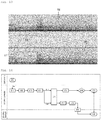
- the figure 14 makes it possible to synthesize the audio reproduction process which has just been described.
- the decoder box transmits an input audio signal Sae, which is in this case a multichannel audio stream (step E10).
- the connected speaker receives the input audio signal Sae via its Wi-Fi interface (step E11).
- the decoder module decodes the input audio signal (step E12).
- the splitter module separates the distributed audio signals (step E13), which are allocated to the Bluetooth speakers paired with the speaker connected.
- a new spatial distribution of the audio channels is optionally carried out (step E14).
- the first distributed audio signal Sar1 is buffered (step E16).
- a frequency equalization is optionally implemented on the second distributed audio signal Sar2 (step E17).
- the second distributed audio signal Sar2 is encoded according to the AD2P codec (step E18).
- the second distributed audio signal Sar2 is then transmitted to the Bluetooth speakers (step E19).
- the connected speaker judges the time elapsed after the start of the transmission of the second distributed audio signal (step E20) and, when the elapsed time is equal to the evaluated transmission and playback latency of the Bluetooth speakers, the connected speaker plays a first signal sound corresponding to the first distributed audio signal (step E21).
- the Bluetooth speakers for their part play a second sound signal corresponding to the second distributed audio signal (step E22).
- the first sound signal and the second sound signal are perfectly synchronized.
Landscapes
- Engineering & Computer Science (AREA)
- Physics & Mathematics (AREA)
- Signal Processing (AREA)
- Acoustics & Sound (AREA)
- Health & Medical Sciences (AREA)
- General Health & Medical Sciences (AREA)
- Otolaryngology (AREA)
- Theoretical Computer Science (AREA)
- Multimedia (AREA)
- Audiology, Speech & Language Pathology (AREA)
- Human Computer Interaction (AREA)
- General Engineering & Computer Science (AREA)
- General Physics & Mathematics (AREA)
- Electromagnetism (AREA)
- Computer Networks & Wireless Communication (AREA)
- Circuit For Audible Band Transducer (AREA)
- Details Of Audible-Bandwidth Transducers (AREA)
Applications Claiming Priority (1)
| Application Number | Priority Date | Filing Date | Title |
|---|---|---|---|
| FR1915298A FR3105500B1 (fr) | 2019-12-20 | 2019-12-20 | Enceinte connectée comprenant une interface LAN et une interface WPAN |
Publications (2)
| Publication Number | Publication Date |
|---|---|
| EP3842923A1 true EP3842923A1 (de) | 2021-06-30 |
| EP3842923B1 EP3842923B1 (de) | 2022-11-30 |
Family
ID=71661908
Family Applications (1)
| Application Number | Title | Priority Date | Filing Date |
|---|---|---|---|
| EP20214599.1A Active EP3842923B1 (de) | 2019-12-20 | 2020-12-16 | Vernetzte box mit einer lan- und einer wpan-schnittstelle |
Country Status (5)
| Country | Link |
|---|---|
| US (1) | US11863966B2 (de) |
| EP (1) | EP3842923B1 (de) |
| CN (1) | CN113099355A (de) |
| BR (1) | BR102020025853A2 (de) |
| FR (1) | FR3105500B1 (de) |
Families Citing this family (1)
| Publication number | Priority date | Publication date | Assignee | Title |
|---|---|---|---|---|
| US11985494B2 (en) * | 2021-04-07 | 2024-05-14 | Steelseries Aps | Apparatus for providing audio data to multiple audio logical devices |
Citations (4)
| Publication number | Priority date | Publication date | Assignee | Title |
|---|---|---|---|---|
| EP2893531A1 (de) * | 2012-09-06 | 2015-07-15 | Sagemcom Broadband SAS | Vorrichtung und verfahren zur übertragung eines referenztonsignals an eine akustische verarbeitungseinheit |
| US20150326986A1 (en) * | 2006-09-12 | 2015-11-12 | Sonos, Inc. | Pair Volume Control |
| US20180020308A1 (en) * | 2016-07-18 | 2018-01-18 | Bose Corporation | Dynamically Changing Master Audio Playback Device |
| US10481859B2 (en) * | 2017-12-07 | 2019-11-19 | Powerchord Group Limited | Audio synchronization and delay estimation |
Family Cites Families (4)
| Publication number | Priority date | Publication date | Assignee | Title |
|---|---|---|---|---|
| US9992729B2 (en) * | 2012-10-22 | 2018-06-05 | The Nielsen Company (Us), Llc | Systems and methods for wirelessly modifying detection characteristics of portable devices |
| US9078072B2 (en) * | 2013-10-07 | 2015-07-07 | Bose Corporation | Audio distribution |
| FR3059507B1 (fr) * | 2016-11-30 | 2019-01-25 | Sagemcom Broadband Sas | Procede de synchronisation d'un premier signal audio et d'un deuxieme signal audio |
| US11350469B2 (en) * | 2019-01-09 | 2022-05-31 | Zagg Inc | Tap to broadcast speaker pairing |
-
2019
- 2019-12-20 FR FR1915298A patent/FR3105500B1/fr not_active Expired - Fee Related
-
2020
- 2020-12-16 US US17/124,052 patent/US11863966B2/en active Active
- 2020-12-16 EP EP20214599.1A patent/EP3842923B1/de active Active
- 2020-12-17 BR BR102020025853-2A patent/BR102020025853A2/pt not_active IP Right Cessation
- 2020-12-21 CN CN202011518462.4A patent/CN113099355A/zh active Pending
Patent Citations (4)
| Publication number | Priority date | Publication date | Assignee | Title |
|---|---|---|---|---|
| US20150326986A1 (en) * | 2006-09-12 | 2015-11-12 | Sonos, Inc. | Pair Volume Control |
| EP2893531A1 (de) * | 2012-09-06 | 2015-07-15 | Sagemcom Broadband SAS | Vorrichtung und verfahren zur übertragung eines referenztonsignals an eine akustische verarbeitungseinheit |
| US20180020308A1 (en) * | 2016-07-18 | 2018-01-18 | Bose Corporation | Dynamically Changing Master Audio Playback Device |
| US10481859B2 (en) * | 2017-12-07 | 2019-11-19 | Powerchord Group Limited | Audio synchronization and delay estimation |
Also Published As
| Publication number | Publication date |
|---|---|
| FR3105500B1 (fr) | 2021-12-17 |
| EP3842923B1 (de) | 2022-11-30 |
| US11863966B2 (en) | 2024-01-02 |
| BR102020025853A2 (pt) | 2021-06-22 |
| US20210195364A1 (en) | 2021-06-24 |
| CN113099355A (zh) | 2021-07-09 |
| FR3105500A1 (fr) | 2021-06-25 |
Similar Documents
| Publication | Publication Date | Title |
|---|---|---|
| EP2042001B1 (de) | Binaurale spatialisierung kompressionsverschlüsselter tondaten | |
| EP1992198B1 (de) | Optimierung des binauralen raumklangeffektes durch mehrkanalkodierung | |
| FR2974655A1 (fr) | Combine audio micro/casque comprenant des moyens de debruitage d'un signal de parole proche, notamment pour un systeme de telephonie "mains libres". | |
| FR3032586A1 (fr) | Appareil de reception et de lecture de signaux audio et systeme de sonorisation live | |
| FR2899423A1 (fr) | Procede et dispositif de spatialisation sonore binaurale efficace dans le domaine transforme. | |
| WO2011045506A1 (fr) | Traitement de donnees sonores encodees dans un domaine de sous-bandes | |
| FR2790634A1 (fr) | Procede de synthese d'un champ sonore tridimensionnel | |
| FR2899424A1 (fr) | Procede de synthese binaurale prenant en compte un effet de salle | |
| EP1586220B1 (de) | Verfahren und einrichtung zur steuerung einer wiedergabeeinheitdurch verwendung eines mehrkanalsignals | |
| FR2998438A1 (fr) | Acquisition de donnees sonores spatialisees | |
| WO2003073791A2 (fr) | Procédé et dispositif de pilotage d'un ensemble de restitution d'un champ acoustique | |
| EP2009891B1 (de) | Übertragung eines Audiosignals in einem immersiven Audiokonferenzsystem | |
| EP3842923B1 (de) | Vernetzte box mit einer lan- und einer wpan-schnittstelle | |
| CN102969003A (zh) | 摄像声音提取方法及装置 | |
| CN114424583A (zh) | 混合近场/远场扬声器虚拟化 | |
| FR3065137A1 (fr) | Procede de spatialisation sonore | |
| FR2955996A1 (fr) | Methode pour creer un environnement audio avec n haut-parleurs | |
| EP3729832B1 (de) | Verarbeitung eines monophonen signals in einem 3d-audiodecodierer, der binauralen inhalt liefert | |
| WO2006075079A1 (fr) | Procede d’encodage de pistes audio d’un contenu multimedia destine a une diffusion sur terminaux mobiles | |
| EP3920552B1 (de) | Zentralisierte verarbeitung eines eingangs-audiodatenstroms | |
| RU2816884C2 (ru) | Аудиоустройство, система распределения аудио и способ их работы | |
| WO2020128214A1 (fr) | Calibration d'un système de restitution sonore distribué | |
| FR2943867A1 (fr) | Traitement d'egalisation de composantes spatiales d'un signal audio 3d | |
| FR2963844A1 (fr) | Procede de determination de parametres definissant des filtres applicables a des haut-parleurs, dispositif et programme associes | |
| CA2974156A1 (fr) | Amplificateur a reglage de niveau sonore automatique |
Legal Events
| Date | Code | Title | Description |
|---|---|---|---|
| PUAI | Public reference made under article 153(3) epc to a published international application that has entered the european phase |
Free format text: ORIGINAL CODE: 0009012 |
|
| STAA | Information on the status of an ep patent application or granted ep patent |
Free format text: STATUS: REQUEST FOR EXAMINATION WAS MADE |
|
| STAA | Information on the status of an ep patent application or granted ep patent |
Free format text: STATUS: EXAMINATION IS IN PROGRESS |
|
| 17P | Request for examination filed |
Effective date: 20201216 |
|
| AK | Designated contracting states |
Kind code of ref document: A1 Designated state(s): AL AT BE BG CH CY CZ DE DK EE ES FI FR GB GR HR HU IE IS IT LI LT LU LV MC MK MT NL NO PL PT RO RS SE SI SK SM TR |
|
| 17Q | First examination report despatched |
Effective date: 20210611 |
|
| GRAP | Despatch of communication of intention to grant a patent |
Free format text: ORIGINAL CODE: EPIDOSNIGR1 |
|
| STAA | Information on the status of an ep patent application or granted ep patent |
Free format text: STATUS: GRANT OF PATENT IS INTENDED |
|
| INTG | Intention to grant announced |
Effective date: 20220624 |
|
| GRAS | Grant fee paid |
Free format text: ORIGINAL CODE: EPIDOSNIGR3 |
|
| GRAA | (expected) grant |
Free format text: ORIGINAL CODE: 0009210 |
|
| STAA | Information on the status of an ep patent application or granted ep patent |
Free format text: STATUS: THE PATENT HAS BEEN GRANTED |
|
| AK | Designated contracting states |
Kind code of ref document: B1 Designated state(s): AL AT BE BG CH CY CZ DE DK EE ES FI FR GB GR HR HU IE IS IT LI LT LU LV MC MK MT NL NO PL PT RO RS SE SI SK SM TR |
|
| REG | Reference to a national code |
Ref country code: CH Ref legal event code: EP Ref country code: GB Ref legal event code: FG4D Free format text: NOT ENGLISH |
|
| REG | Reference to a national code |
Ref country code: AT Ref legal event code: REF Ref document number: 1535182 Country of ref document: AT Kind code of ref document: T Effective date: 20221215 Ref country code: DE Ref legal event code: R096 Ref document number: 602020006615 Country of ref document: DE |
|
| REG | Reference to a national code |
Ref country code: IE Ref legal event code: FG4D Free format text: LANGUAGE OF EP DOCUMENT: FRENCH |
|
| REG | Reference to a national code |
Ref country code: LT Ref legal event code: MG9D |
|
| REG | Reference to a national code |
Ref country code: NL Ref legal event code: MP Effective date: 20221130 |
|
| PG25 | Lapsed in a contracting state [announced via postgrant information from national office to epo] |
Ref country code: SE Free format text: LAPSE BECAUSE OF FAILURE TO SUBMIT A TRANSLATION OF THE DESCRIPTION OR TO PAY THE FEE WITHIN THE PRESCRIBED TIME-LIMIT Effective date: 20221130 Ref country code: PT Free format text: LAPSE BECAUSE OF FAILURE TO SUBMIT A TRANSLATION OF THE DESCRIPTION OR TO PAY THE FEE WITHIN THE PRESCRIBED TIME-LIMIT Effective date: 20230331 Ref country code: NO Free format text: LAPSE BECAUSE OF FAILURE TO SUBMIT A TRANSLATION OF THE DESCRIPTION OR TO PAY THE FEE WITHIN THE PRESCRIBED TIME-LIMIT Effective date: 20230228 Ref country code: LT Free format text: LAPSE BECAUSE OF FAILURE TO SUBMIT A TRANSLATION OF THE DESCRIPTION OR TO PAY THE FEE WITHIN THE PRESCRIBED TIME-LIMIT Effective date: 20221130 Ref country code: FI Free format text: LAPSE BECAUSE OF FAILURE TO SUBMIT A TRANSLATION OF THE DESCRIPTION OR TO PAY THE FEE WITHIN THE PRESCRIBED TIME-LIMIT Effective date: 20221130 Ref country code: ES Free format text: LAPSE BECAUSE OF FAILURE TO SUBMIT A TRANSLATION OF THE DESCRIPTION OR TO PAY THE FEE WITHIN THE PRESCRIBED TIME-LIMIT Effective date: 20221130 |
|
| REG | Reference to a national code |
Ref country code: AT Ref legal event code: MK05 Ref document number: 1535182 Country of ref document: AT Kind code of ref document: T Effective date: 20221130 |
|
| PG25 | Lapsed in a contracting state [announced via postgrant information from national office to epo] |
Ref country code: RS Free format text: LAPSE BECAUSE OF FAILURE TO SUBMIT A TRANSLATION OF THE DESCRIPTION OR TO PAY THE FEE WITHIN THE PRESCRIBED TIME-LIMIT Effective date: 20221130 Ref country code: PL Free format text: LAPSE BECAUSE OF FAILURE TO SUBMIT A TRANSLATION OF THE DESCRIPTION OR TO PAY THE FEE WITHIN THE PRESCRIBED TIME-LIMIT Effective date: 20221130 Ref country code: LV Free format text: LAPSE BECAUSE OF FAILURE TO SUBMIT A TRANSLATION OF THE DESCRIPTION OR TO PAY THE FEE WITHIN THE PRESCRIBED TIME-LIMIT Effective date: 20221130 Ref country code: IS Free format text: LAPSE BECAUSE OF FAILURE TO SUBMIT A TRANSLATION OF THE DESCRIPTION OR TO PAY THE FEE WITHIN THE PRESCRIBED TIME-LIMIT Effective date: 20230330 Ref country code: HR Free format text: LAPSE BECAUSE OF FAILURE TO SUBMIT A TRANSLATION OF THE DESCRIPTION OR TO PAY THE FEE WITHIN THE PRESCRIBED TIME-LIMIT Effective date: 20221130 Ref country code: GR Free format text: LAPSE BECAUSE OF FAILURE TO SUBMIT A TRANSLATION OF THE DESCRIPTION OR TO PAY THE FEE WITHIN THE PRESCRIBED TIME-LIMIT Effective date: 20230301 |
|
| PG25 | Lapsed in a contracting state [announced via postgrant information from national office to epo] |
Ref country code: NL Free format text: LAPSE BECAUSE OF FAILURE TO SUBMIT A TRANSLATION OF THE DESCRIPTION OR TO PAY THE FEE WITHIN THE PRESCRIBED TIME-LIMIT Effective date: 20221130 |
|
| PG25 | Lapsed in a contracting state [announced via postgrant information from national office to epo] |
Ref country code: SM Free format text: LAPSE BECAUSE OF FAILURE TO SUBMIT A TRANSLATION OF THE DESCRIPTION OR TO PAY THE FEE WITHIN THE PRESCRIBED TIME-LIMIT Effective date: 20221130 Ref country code: RO Free format text: LAPSE BECAUSE OF FAILURE TO SUBMIT A TRANSLATION OF THE DESCRIPTION OR TO PAY THE FEE WITHIN THE PRESCRIBED TIME-LIMIT Effective date: 20221130 Ref country code: EE Free format text: LAPSE BECAUSE OF FAILURE TO SUBMIT A TRANSLATION OF THE DESCRIPTION OR TO PAY THE FEE WITHIN THE PRESCRIBED TIME-LIMIT Effective date: 20221130 Ref country code: DK Free format text: LAPSE BECAUSE OF FAILURE TO SUBMIT A TRANSLATION OF THE DESCRIPTION OR TO PAY THE FEE WITHIN THE PRESCRIBED TIME-LIMIT Effective date: 20221130 Ref country code: CZ Free format text: LAPSE BECAUSE OF FAILURE TO SUBMIT A TRANSLATION OF THE DESCRIPTION OR TO PAY THE FEE WITHIN THE PRESCRIBED TIME-LIMIT Effective date: 20221130 Ref country code: AT Free format text: LAPSE BECAUSE OF FAILURE TO SUBMIT A TRANSLATION OF THE DESCRIPTION OR TO PAY THE FEE WITHIN THE PRESCRIBED TIME-LIMIT Effective date: 20221130 |
|
| REG | Reference to a national code |
Ref country code: BE Ref legal event code: MM Effective date: 20221231 |
|
| PG25 | Lapsed in a contracting state [announced via postgrant information from national office to epo] |
Ref country code: SK Free format text: LAPSE BECAUSE OF FAILURE TO SUBMIT A TRANSLATION OF THE DESCRIPTION OR TO PAY THE FEE WITHIN THE PRESCRIBED TIME-LIMIT Effective date: 20221130 Ref country code: LU Free format text: LAPSE BECAUSE OF NON-PAYMENT OF DUE FEES Effective date: 20221216 Ref country code: AL Free format text: LAPSE BECAUSE OF FAILURE TO SUBMIT A TRANSLATION OF THE DESCRIPTION OR TO PAY THE FEE WITHIN THE PRESCRIBED TIME-LIMIT Effective date: 20221130 |
|
| REG | Reference to a national code |
Ref country code: DE Ref legal event code: R097 Ref document number: 602020006615 Country of ref document: DE |
|
| PLBE | No opposition filed within time limit |
Free format text: ORIGINAL CODE: 0009261 |
|
| STAA | Information on the status of an ep patent application or granted ep patent |
Free format text: STATUS: NO OPPOSITION FILED WITHIN TIME LIMIT |
|
| PG25 | Lapsed in a contracting state [announced via postgrant information from national office to epo] |
Ref country code: IE Free format text: LAPSE BECAUSE OF NON-PAYMENT OF DUE FEES Effective date: 20221216 |
|
| 26N | No opposition filed |
Effective date: 20230831 |
|
| PG25 | Lapsed in a contracting state [announced via postgrant information from national office to epo] |
Ref country code: SI Free format text: LAPSE BECAUSE OF FAILURE TO SUBMIT A TRANSLATION OF THE DESCRIPTION OR TO PAY THE FEE WITHIN THE PRESCRIBED TIME-LIMIT Effective date: 20221130 Ref country code: BE Free format text: LAPSE BECAUSE OF NON-PAYMENT OF DUE FEES Effective date: 20221231 |
|
| PGFP | Annual fee paid to national office [announced via postgrant information from national office to epo] |
Ref country code: FR Payment date: 20231122 Year of fee payment: 4 Ref country code: DE Payment date: 20231121 Year of fee payment: 4 |
|
| PG25 | Lapsed in a contracting state [announced via postgrant information from national office to epo] |
Ref country code: CY Free format text: LAPSE BECAUSE OF FAILURE TO SUBMIT A TRANSLATION OF THE DESCRIPTION OR TO PAY THE FEE WITHIN THE PRESCRIBED TIME-LIMIT Effective date: 20221130 |
|
| PG25 | Lapsed in a contracting state [announced via postgrant information from national office to epo] |
Ref country code: MK Free format text: LAPSE BECAUSE OF FAILURE TO SUBMIT A TRANSLATION OF THE DESCRIPTION OR TO PAY THE FEE WITHIN THE PRESCRIBED TIME-LIMIT Effective date: 20221130 Ref country code: IT Free format text: LAPSE BECAUSE OF FAILURE TO SUBMIT A TRANSLATION OF THE DESCRIPTION OR TO PAY THE FEE WITHIN THE PRESCRIBED TIME-LIMIT Effective date: 20221130 |
|
| PG25 | Lapsed in a contracting state [announced via postgrant information from national office to epo] |
Ref country code: MC Free format text: LAPSE BECAUSE OF FAILURE TO SUBMIT A TRANSLATION OF THE DESCRIPTION OR TO PAY THE FEE WITHIN THE PRESCRIBED TIME-LIMIT Effective date: 20221130 |
|
| PG25 | Lapsed in a contracting state [announced via postgrant information from national office to epo] |
Ref country code: MC Free format text: LAPSE BECAUSE OF FAILURE TO SUBMIT A TRANSLATION OF THE DESCRIPTION OR TO PAY THE FEE WITHIN THE PRESCRIBED TIME-LIMIT Effective date: 20221130 |
|
| PG25 | Lapsed in a contracting state [announced via postgrant information from national office to epo] |
Ref country code: BG Free format text: LAPSE BECAUSE OF FAILURE TO SUBMIT A TRANSLATION OF THE DESCRIPTION OR TO PAY THE FEE WITHIN THE PRESCRIBED TIME-LIMIT Effective date: 20221130 |
|
| REG | Reference to a national code |
Ref country code: CH Ref legal event code: PL |