EP3842701A1 - Apparatus, system and method for controlling airflow - Google Patents
Apparatus, system and method for controlling airflow Download PDFInfo
- Publication number
- EP3842701A1 EP3842701A1 EP20153412.0A EP20153412A EP3842701A1 EP 3842701 A1 EP3842701 A1 EP 3842701A1 EP 20153412 A EP20153412 A EP 20153412A EP 3842701 A1 EP3842701 A1 EP 3842701A1
- Authority
- EP
- European Patent Office
- Prior art keywords
- air guide
- guide member
- airflow
- outlet
- flared bore
- Prior art date
- Legal status (The legal status is an assumption and is not a legal conclusion. Google has not performed a legal analysis and makes no representation as to the accuracy of the status listed.)
- Withdrawn
Links
Images


Classifications
-
- F—MECHANICAL ENGINEERING; LIGHTING; HEATING; WEAPONS; BLASTING
- F24—HEATING; RANGES; VENTILATING
- F24F—AIR-CONDITIONING; AIR-HUMIDIFICATION; VENTILATION; USE OF AIR CURRENTS FOR SCREENING
- F24F13/00—Details common to, or for air-conditioning, air-humidification, ventilation or use of air currents for screening
- F24F13/02—Ducting arrangements
- F24F13/06—Outlets for directing or distributing air into rooms or spaces, e.g. ceiling air diffuser
-
- B—PERFORMING OPERATIONS; TRANSPORTING
- B60—VEHICLES IN GENERAL
- B60H—ARRANGEMENTS OF HEATING, COOLING, VENTILATING OR OTHER AIR-TREATING DEVICES SPECIALLY ADAPTED FOR PASSENGER OR GOODS SPACES OF VEHICLES
- B60H1/00—Heating, cooling or ventilating [HVAC] devices
- B60H1/34—Nozzles; Air-diffusers
- B60H1/3414—Nozzles; Air-diffusers with means for adjusting the air stream direction
-
- B—PERFORMING OPERATIONS; TRANSPORTING
- B60—VEHICLES IN GENERAL
- B60H—ARRANGEMENTS OF HEATING, COOLING, VENTILATING OR OTHER AIR-TREATING DEVICES SPECIALLY ADAPTED FOR PASSENGER OR GOODS SPACES OF VEHICLES
- B60H1/00—Heating, cooling or ventilating [HVAC] devices
- B60H1/34—Nozzles; Air-diffusers
- B60H1/345—Nozzles; Air-diffusers with means for adjusting divergence, convergence or oscillation of air stream
-
- F—MECHANICAL ENGINEERING; LIGHTING; HEATING; WEAPONS; BLASTING
- F24—HEATING; RANGES; VENTILATING
- F24F—AIR-CONDITIONING; AIR-HUMIDIFICATION; VENTILATION; USE OF AIR CURRENTS FOR SCREENING
- F24F11/00—Control or safety arrangements
- F24F11/70—Control systems characterised by their outputs; Constructional details thereof
- F24F11/72—Control systems characterised by their outputs; Constructional details thereof for controlling the supply of treated air, e.g. its pressure
- F24F11/79—Control systems characterised by their outputs; Constructional details thereof for controlling the supply of treated air, e.g. its pressure for controlling the direction of the supplied air
-
- F—MECHANICAL ENGINEERING; LIGHTING; HEATING; WEAPONS; BLASTING
- F24—HEATING; RANGES; VENTILATING
- F24F—AIR-CONDITIONING; AIR-HUMIDIFICATION; VENTILATION; USE OF AIR CURRENTS FOR SCREENING
- F24F13/00—Details common to, or for air-conditioning, air-humidification, ventilation or use of air currents for screening
- F24F13/08—Air-flow control members, e.g. louvres, grilles, flaps or guide plates
- F24F13/10—Air-flow control members, e.g. louvres, grilles, flaps or guide plates movable, e.g. dampers
- F24F13/14—Air-flow control members, e.g. louvres, grilles, flaps or guide plates movable, e.g. dampers built up of tilting members, e.g. louvre
- F24F13/1413—Air-flow control members, e.g. louvres, grilles, flaps or guide plates movable, e.g. dampers built up of tilting members, e.g. louvre using more than one tilting member, e.g. with several pivoting blades
Definitions
- This invention relates to an airflow apparatus, a system comprising the airflow apparatus, and a method of operating the airflow apparatus.
- cooling fans may swivel on a base in order to direct airflow in different directions. Motorized control over the swiveling of the cooling fan may also permit the airflow to be swept across a range of different directions.
- a disadvantage of such conventional air delivery appliances relates to the space required in order to enable adjustment of the airflow.
- swiveling the cooling fan may require that sufficient space is provided around the cooling fan in order to accommodate its movement.
- Conventional air conditioning appliances may, for example, comprise adjustable grilles.
- the grilles may be adjusted according to the desired airflow direction or may be controlled to direct the airflow across a range of directions.
- Such grille designs may, however, also mean that compactness of the appliance is compromised, with limitations being placed on the design flexibility of the appliance as a whole.
- an airflow apparatus comprising: an outlet for allowing air to flow out of the apparatus; a wall delimiting a flared bore which widens to the outlet; and at least one air guide member configured to retractably protrude into the flared bore from the wall, the at least one air guide member having a surface for guiding air flowing in the flared bore away from the wall and towards the outlet when the air guide member is protruding into the flared bore.
- the present invention is based on the realization that the direction and/or convergence of air flowing out of the outlet of an airflow apparatus may be controlled by the apparatus including a wall defining a flared bore which widens to the outlet, and at least one air guide member which retractably protrudes into the flared bore.
- the apparatus including a wall defining a flared bore which widens to the outlet, and at least one air guide member which retractably protrudes into the flared bore.
- the at least one air guide member may thus assist to control the direction of and/or converge the airflow, relative to when the at least one air guide member is retracted. Such adjustment is enabled without, for example, changing the position of the flared bore/outlet, which may enable the airflow apparatus to have a compact and flexible design.
- the wall may comprise a curved surface whose curvature in the direction of the outlet defines the flared bore.
- the airflow may follow the curved surface of the wall and thus form, when the at least one air guide member is retracted, a diverged flow pattern from the outlet.
- the airflow adhering to the curved surface of the wall in this manner is a phenomenon known as the Coand effect.
- the protrusion of the air guide members into the flared bore effectively interrupts the airflow following the curved surface of the wall, thereby to enable control over the direction and/or degree of convergence of the airflow leaving the outlet.
- the surface of the at least one air guide member may, for example, comprise a concave surface.
- the concave surface may advantageously define, together with the surface of the flared bore, a substantially continuous, e.g. streamlined, air guiding surface when the respective air guide member is protruding into the flared bore. This may result in more efficient operation of the apparatus, with less noise and turbulence being generated when the air guide member is protruded, e.g. relative to an air guide member having a non-curved surface for guiding the airflow.
- the at least one air guide member is retractable through a slot in the wall.
- the slot may, for example, enable complete retraction of the at least one air guide member out of the flared bore.
- the air guide member(s) may not interfere with airflow through the flared bore when completely retracted into the respective slot(s).
- the extent or degree to which the at least one air guide member protrudes into the flared bore may, for example, be adjustable. Such adjustment may, for instance, be implemented by controlling the retraction/protrusion of each air guide member through the respective slot (when such a slot is provided in the wall). Adjusting the protrusion of the air guide member(s) in this manner may provide further control over the airflow emerging from the outlet of the airflow apparatus, e.g. in comparison to the scenario in which only a single extent of protrusion of the air guide member(s) into the flared bore can be selected.
- Each of the at least one air guide member may be curved so as to define an arch against an outer surface of the wall when retracted. This may assist in making the design compact.
- the retraction and/or protrusion of the air guide member may be realized using any suitable mechanism.
- the mechanism may be manually and/or electrically operated.
- An electrically operated retraction mechanism may, for example, enable the air guide member to be retracted and/or protruded via control signals sent by a controller.
- the electrically operated mechanism may be configured to provide linear motion, e.g. using a rack-and-pinion and linear motor.
- a controller may send a signal defining the rotation direction of the pinion or the movement direction of the linear motor in order to realize bidirectional motion of the respective air guide member.
- each of the at least one air guide member when protruding into the flared bore, may meet an axis extending between opposing portions of the wall at a distance along the axis from the wall which is less than one third of a width of the flared bore between the opposing portions.
- the extent of protrusion of the air guide member into the flared bore may thus be restricted in order to assist the air guide member to direct the airflow towards the outlet, rather than towards the wall, when protruding into the flared bore.
- the airflow apparatus may comprise an air displacement device configured to provide a flow of air into the flared bore and out of the outlet.
- the air displacement device may, for example, comprise a fan.
- the airflow apparatus may, for example, be included in an air purifier; purified air being expelled from the outlet.
- a method for operating an airflow apparatus including: an outlet for allowing air to flow out of the apparatus; a wall delimiting a flared bore which widens to the outlet; and at least one air guide member configured to retractably protrude into the flared bore from the wall, the at least one air guide member having a surface, the method comprising: protruding the at least one air guide member into the flared bore, such that air flowing in the flared bore is guided by the surface away from the wall and towards the outlet.
- the method further comprises retracting the at least one air guide member from the flared bore.
- the protruding and/or the retracting may, for instance, be implemented in a sequence, thereby providing a dynamic airflow from the outlet.
- the at least one air guide member may comprise a series of air guide members which are respectively arranged to protrude into the flared bore from positions along the wall which are successively closer to the outlet.
- the series of air guide members may enable further control over the degree of convergence of the airflow from the outlet. When, for example, a greater degree of convergence is desired, an air guide member of the series positioned further away from the outlet may be protruded into the flared bore. When a lesser degree of convergence is desired, an air guide member of the series positioned closer to the outlet may instead be protruded into the flared bore.
- the method comprises selecting at least one of the air guide members of the series based on a desired direction and/or degree of convergence of airflow from the outlet.
- the protruding may comprise protruding the selected at least one of the respective air guide members of the series into the flared bore.
- the at least one air guide member may alternatively or additionally comprise a pair of air guide members which are respectively arranged to protrude into the flared bore from opposing parts of the wall.
- the pair of air guide members may enable further control over the direction of the airflow from the outlet.
- the airflow may be guided away from the air guide member towards a distal area of the outlet (relative to the position of the single air guide member).
- both air guide members of the pair are protruded into the flared bore, their combined air guiding effect may result in a converged airflow emerging from a central area of the outlet.
- the method comprises selecting one or both of the air guide members of the pair based on a desired direction and/or degree of convergence of airflow from the outlet.
- the protruding may comprise protruding the selected one or both air guide members of the pair of air guide members into the flared bore.
- the airflow from the outlet may, for example, be tuned by combining selection of the at least one of the air guide members of the series with selection of one or both of the air guide members of the pair.
- a system comprising: the apparatus as defined above; and a controller configured to control the protrusion and/or retraction of the at least one air guide member.
- the controller may, for example, be configured to control the protrusion and/or retraction of the at least one air guide member in a sequence and/or loop, thereby to provide a dynamic airflow from the outlet.
- the controller may be configured to receive an indication relating to a desired direction and/or degree of convergence of airflow from the outlet, and control the protrusion and/or retraction of the at least one air guide member based on the indication.
- the system may, for instance, comprise a user interface for permitting user input of the indication.
- the controller may be configured to receive the indication from the user interface, and control the protrusion and/or retraction of the at least one air guide member accordingly.
- the controller may be configured to: select at least one of the air guide members of the series based on the received indication; and control the at least one air guide member such that the selected at least one of the respective air guide members of the series is protruded into the flared bore.
- the controller may be configured to: select one or both of the air guide members from the pair of air guide members based on the received indication; and control the at least one air guide member such that the selected one or both of the air guide members of the pair of air guide members is or are protruded into the flared bore.
- an air delivery appliance comprising the apparatus or the system defined above.
- the air delivery appliance may, for example, be a household or commercial appliance.
- the airflow apparatus may receive a flow of air in the flared bore, and control the direction and/or convergence of the air being expelled from the outlet, which may also define an outlet of the air delivery appliance.
- the air delivery appliance may be, for instance, a cooling fan, an air purifier, such as a fresh air purification unit, an air humidifier, and/or an air conditioner.
- an air purifier such as a fresh air purification unit, an air humidifier, and/or an air conditioner.
- an airflow apparatus for controlling the direction and/or degree of convergence of air flowing from an outlet.
- the apparatus comprises a wall which delimits a flared bore.
- the apparatus further comprises at least one air guide member which retractably protrudes into the flared bore from the wall.
- the flared bore widens to the outlet, thereby to permit a diverging airflow to be expelled therefrom when each of the at least one air guide member is retracted.
- air flowing in the flared bore is guided by a surface, e.g. a concave surface, of the respective air guide member away from the wall and towards the outlet.
- the retractable air guide member thus enables the direction and/or degree of convergence of the air flowing out of the outlet to be controlled. Further provided is a system comprising the apparatus and a controller for controlling the protrusion/retraction of the at least one air guide member. A method of operating the airflow apparatus is also disclosed.
- the present invention is based on the realization that the direction and/or convergence of air flowing out of the outlet of an airflow apparatus may be controlled by the apparatus including a wall defining a flared bore which widens to the outlet, and at least one air guide member which retractably protrudes into the flared bore.
- the apparatus including a wall defining a flared bore which widens to the outlet, and at least one air guide member which retractably protrudes into the flared bore.
- the at least one air guide member may thus assist to control the direction of and/or converge the airflow, relative to when the at least one air guide member is retracted. Such adjustment is enabled without, for example, changing the position of the flared bore/outlet, which may enable the airflow apparatus to have a compact and flexible design.
- This flared bore of the airflow apparatus may be a stationary structure which is nevertheless capable of generating dynamic airflow patterns via the retractable air guide member(s).
- the airflow apparatus may generate various airflow patterns, including focused, dispersed, tilted, oscillating, or any combination of these, as will be described in greater detail herein below.
- Extending the air guide member(s) into the flared channel may, at least in some examples, be regarded as enabling control over airflow patterns via selectively activating or deactivating the Coand effect over a defined section of the surface of the wall which delimits the flared bore.
- This design may, in some examples, lead to improved compactness, reduced structural complexity and lower cost, lower noise generation, and improved mechanical reliability relative to conventional air delivery appliances.
- Fig. 1 schematically depicts a cross-section of an apparatus 100 according to a non-limiting example.
- the apparatus 100 receives an airflow via an inlet 101.
- the airflow may be generated, for example, by an air displacement device (not shown in Fig. 1 ).
- the air displacement device is included in the airflow apparatus 100.
- the air displacement device may be included in an air delivery appliance from which the airflow is received by the apparatus 100 via the inlet 101.
- the airflow apparatus 100 may be employed to control the direction and/or convergence of the airflow passing out of the apparatus 100 via the outlet 102.
- the air displacement device may, for instance, comprise a fan whose rotating fan blades displace air in order to generate the airflow.
- the airflow may, for example, be passed through air treatment components, e.g. one or more filters, a humidifier, a cooling unit, etc., prior to reaching the inlet 101 of the apparatus 100.
- the outlet 102 of the apparatus 100 may also define the outlet of the air delivery appliance.
- the air delivery appliance may be, for instance, a cooling fan, an air purifier, such as a fresh air purification unit, an air humidifier, and/or an air conditioner.
- an air purifier such as a fresh air purification unit, an air humidifier, and/or an air conditioner.
- the purified air may be expelled from the outlet 102.
- the airflow apparatus 100 comprises, as shown in Fig. 1 , a bore 103 delimited by a wall 104.
- the air flows through the bore 103 to the outlet 102, as represented by the arrows in Fig. 1 .
- the inner surface of the wall 104 may be curved, such that the airflow adheres to the wall 104 as it passes through the bore 103.
- the airflow adhering to the curved surface of the wall 104 in this manner is a phenomenon known as the Coand effect.
- the bore 103 smoothly narrows from a first wall region 105A to a second wall region 105B, before smoothly widening to the outlet 102.
- the widening of the bore 103 from the second wall region 105B to the outlet 102 corresponds to the flared bore 106.
- the curvature of the surface of the wall 104 shown in Fig. 1 may assist to provide a diverged airflow from the outlet 102, as represented by the hashed arrows emerging from the outlet 102.
- a relatively diffuse airflow out of the outlet 102 may result whose divergence is defined by the widening of the flared bore 106 towards the outlet 102.
- the diverging airflow pattern is represented in Fig. 1 by the double-headed hashed arrow 107A.
- the airflow apparatus 100 comprises at least one air guide member 108, 110 which retractably protrudes into the flared bore 106.
- each of the at least one air guide member 108, 110 is retracted.
- the air guide member(s) 108, 110 may not, or only negligibly, interrupt the airflow in the flared bore 106, such that the diverging airflow pattern 107A may be solely, or primarily, determined by the flared bore 106.
- the at least one air guide member 108, 110 may be retractable from and protrudable into the flared bore 106 in any suitable manner.
- the at least one air guide member 108, 110 is retractable through a slot (not visible) in the wall 104.
- the slot may, for example, enable complete retraction of the at least one air guide member 108, 110 out of the flared bore 106.
- the completely retracted air guide member(s) 108, 110 may not, or only negligibly, interfere with airflow through the flared bore 106.
- the airflow apparatus 100 comprises a plurality of air guide members 108, 110, and each of the plurality of air guide members 108, 110 is retractable, e.g. via a respective slot, independently of the other air guide member or members 108, 110.
- the capability to protrude and retract each air guide member 108, 110 independently of the other(s) may enhance the airflow control which can be provided by the apparatus 100.
- at least some of the air guide members 108, 110 may be retracted and protruded together, which may permit the retraction mechanism to be simplified.
- the retraction and/or protrusion of the air guide member(s) 108, 110 may be realized using any suitable mechanism.
- the mechanism may be manually and/or electrically operated.
- each of the at least one air guide member 108, 110 may be protruded into the flared bore 106 and retracted therefrom by the user manually operating a lever or handle.
- An electrically operated retraction mechanism may, for example, enable the air guide member(s) 108, 110 to be retracted and/or protruded via control signals sent by a controller, as will be described in greater detail herein below with reference to FIG. 10 .
- the apparatus 100 comprises an electrically operated mechanism for protruding and/or retracting the air guide members 108, 110
- the mechanism may be configured to provide linear motion, e.g. via a rack-and-pinion and linear motor.
- each of the at least one air guide member 108, 110 is curved so as to define an arch against an outer surface of the wall 104 when retracted. This may assist in making the design compact because the air guide member(s) may be disposed close to the wall 104 when retracted.
- Fig. 2 schematically depicts the apparatus 100 shown in Fig. 1 , but with an air guide member 108A protruding into the flared bore 106.
- a surface of the air guide member 108A guides the air flowing close to the wall 104 away from the wall 104, but still towards the outlet 102.
- the air guide member 108, 110 may, for example, be regarded as deactivating the the Coand effect provided by the flared bore 106.
- the predominant direction of the airflow may be determined by the protrusion of the air guide member 108A into the flared bore 106.
- a more converged airflow pattern 107A is also evident in Fig. 2 , as compared to the airflow pattern 107A in Fig. 1 when no air flow member 108, 110 is protruded into the flared bore 106.
- the surface of the air guide member 108, 110 which guides the airflow, when the respective air guide member 108, 110 is protruded into the flared bore 106, may have any suitable shape, provided that the air guide member 108, 110 is able to guide the air flowing close to the wall 104 away from the wall 104, and towards the outlet 102.
- the surface of the at least one air guide member 108, 110 comprises a concave surface.
- the concave surface of the protruding air guide member 108A may define, together with the surface of the flared bore 106, a substantially continuous, e.g. streamlined, air guiding surface. This may result in more efficient operation of the apparatus 100, with less noise and turbulence being generated when the air guide member 108A is protruded, e.g. relative to an air guide member 108, 110 having a non-curved surface for guiding the airflow.
- an extremity 112 of each of the at least one air guide member 108, 110 when protruding into the flared bore 106, may meet an axis 114 extending between opposing portions of the wall 104 at a distance along the axis 114 from the wall 104 which is less than one third of a width 116 of the flared bore 106 between the opposing portions.
- the extent of protrusion of the air guide member(s) 108, 110 into the flared bore 106 may thus be restricted in order to assist the protruding air guide member 108, 110 to direct the airflow towards the outlet 102, rather than towards the wall 104.
- the air guide members 108, 110 may, for example, all have substantially the same dimensions, e.g. length and curvature, and may thus all protrude by the same distance from the wall 104. In other examples, the air guide members 108, 110 may have different dimensions relative to each other.
- the degree or extent of protrusion/retraction of the at least one air guide member 108, 110 may in some examples be controlled, e.g. via an electrically operated retraction mechanism, in order to control the characteristics of the airflow emerging from the outlet 102 of the airflow apparatus 100.
- the at least one air guide member 108, 110 comprises a series of air guide members 108A, 108B, 108C which are respectively arranged to protrude into the flared bore 106 from positions along the wall 104 which are successively closer to the outlet 102.
- the series of air guide members 108A, 108B, 108C may enable further control over the degree of convergence of the airflow from the outlet 102, as shown in FIGs. 2-4 .
- the air guide member 108A which is furthest from the outlet 102 is protruded into the flared bore 106, while the other air guide members 108B, 108C are retracted.
- FIG. 2 the air guide member 108A which is furthest from the outlet 102 is protruded into the flared bore 106, while the other air guide members 108B, 108C are retracted.
- the air guide member 108C which is closest to the outlet 102 is protruded into the flared bore 106, while the other air guide members 108A, 108B are retracted. Due to the widening of the flared bore 106, and also owing to the air guide members 108A, 108C protruding from the wall 104 to substantially the same degree, the airflow pattern 107A shown in FIG. 2 is more converged than that shown in FIG. 4 .
- FIG. 3 the only protruded air guide member 108B is between the air guide members 108A, 108C which are respectively protruded in FIGs. 1 and 4 .
- An intermediate degree of convergence of the airflow pattern 107A is therefore shown in FIG. 3 relative to the more converged and less converged air flow patterns 107A of the configurations shown in FIGs. 2 and 4 respectively.
- the predominant direction 107B of the airflow may also be tuned.
- the degree of tilting of the airflow direction 107B relative to a central axis of the flared bore 106 may decrease with proximity of the air guide member 108, 110 of the series towards the outlet 102.
- the configurations shown in FIGs. 2-4 may thus be regarded as demonstrating the capability of the airflow apparatus 100 to provide tilted airflows with different degrees of asymmetry and divergence.
- the apparatus 100 comprises the series of air guide members 108A, 108B, 108C which protrude into the flared bore 106 from positions along the wall 104 which are successively closer to the outlet 102
- selectively protruding respective air guide member(s) of the series may permit enhanced control over the direction and/or degree of convergence of the airflow emerging from the outlet 102.
- the at least one air guide member 108, 110 comprises at least one pair of air guide members 108A, 110A; 108B, 110B; 108C, 110C.
- the air guide members 108, 110 of the pair are respectively arranged to protrude into the flared bore 106 from opposing parts 118A, 118B of the wall 104.
- the airflow may be guided away from the protruding air guide member 108, 110 towards a distal area of the outlet 102 (relative to the position of the single air guide member 108, 110), as shown in FIGs. 2-4 .
- both air guide members 108, 110 of the pair are protruded into the flared bore 106, their combined air guiding effect may result in a converged symmetric airflow emerging from the outlet 102.
- FIG. 5 schematically depicts the airflow apparatus 100 shown in FIG. 1 , but in a configuration in which both air guide members 108A, 110A of an opposing pair are protruding into the flared bore 106.
- the resulting airflow pattern 107A is converged relative to, for example, the airflow pattern 107A shown in FIG. 1 .
- the air flowing along the wall part 118A is guided away from the wall 104 by the air guide member 110A to a similar degree as the air flowing along the opposing wall part 118B by the opposing air guide member 108A.
- This may result in the converged airflow from the outlet 102 being symmetrical about the central axis of the flared bore 106.
- FIGs. 2-4 in which the predominant direction of the airflow 107B is angled or tilted to varying degrees relative to the central axis of the flared bore 106.
- the retractable air guide member(s) 108, 110 may assist to control the convergence of the airflow, as shown in FIG. 5 , or both the convergence and the predominant direction 107B of the airflow, as shown in FIGs. 2-4 , relative to the airflow pattern 107A provided by the configuration shown in FIG. 1 .
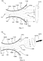
- FIG. 6 schematically depicts an exemplary configuration in which both air guide members 108B, 110B of a different pair (from the protruding pair 108A, 110A of FIG. 5 ) protrude into the flared bore 106.
- the resulting airflow pattern 107A in FIG. 6 is converged relative to the airflow pattern 107A shown in FIG. 1 .
- the airflow pattern 107A shown in FIG. 6 is less converged relative to that of the configuration of FIG.
- the exemplary configuration depicted in FIG. 7 provides a less converged airflow pattern 107A than that shown in FIG. 6 due to the protruding pair of air guide members 108C, 110C being positioned closer to the outlet 102 along the wall 104 of the flared bore 106 than the air guide members 108B, 110B (and protrude from the wall 104 to a similar, or the same, degree).
- a plurality of pairs of retractable air guide member 108A, 110A; 108B, 110B; 108C, 110C, which pairs are positioned successively closer to the outlet 102, may assist in controlling the convergence of the airflow from the outlet 102.
- the airflow from the outlet 102 may, for example, be tuned by combining selection of one of the air guide members 108, 110 of the series with selection of one or both of the air guide members 108, 110 of the opposing pair.
- FIG. 8 schematically depicts the apparatus 100 shown in FIG. 1 , in which non-opposing air guide members 108A, 110C on respective opposing parts 118A, 118B of the wall 104 are protruding into the flared bore 106.
- the resulting airflow pattern 107A is converged, relative to that provided by, for example, the configuration of FIG. 1 in which all of the air guide members 108, 110 are retracted, and that of the configurations shown in FIGs. 2-4 in which only a single air guide member 108, 110 is protruding into the flared bore 106.
- the protrusion of the non-opposing air guide members 108A, 110C causes the predominant direction of the airflow 107B to be angled or tilted relative to the central axis of the flared bore 106.
- the configuration shown in FIG. 8 may be regarded as providing tilted but converged airflow.
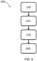
- FIG. 9 shows a flowchart of a method 200 according to an example.
- the method 200 involves operating an airflow apparatus having an outlet for allowing air to flow out of the apparatus; a wall delimiting a flared bore which widens to the outlet; and at least one air guide member configured to retractably protrude into the flared bore from the wall, the at least one air guide member having a surface.
- the method 200 may, for instance, relate to operation of the airflow apparatus 100 described above in relation to FIGs. 1-8 .
- the method 200 comprises protruding 230 the at least one air guide member into the flared bore, such that air flowing in the flared bore is guided by the surface away from the wall and towards the outlet.
- the method 200 further comprises retracting 240 the at least one air guide member from the flared bore.
- the protruding 230 and/or the retracting 240 may, for instance, be implemented in a sequence and/or loop, thereby providing a dynamic airflow from the outlet.
- the at least one air guide member comprises a series of air guide members which are respectively arranged to protrude into the flared bore from positions along the wall which are successively closer to the outlet, as previously described in relation to FIGs. 2-4 , and the method 200 comprises selecting 210 at least one of the air guide members of the series based on a desired direction and/or degree of convergence of airflow from the outlet.
- the protruding 230 may then comprise protruding the selected at least one of the respective air guide members of the series into the flared bore.
- the at least one air guide member comprises a pair of opposing air guide members, as previously described in relation to FIGs. 5-7 , and the method 200 comprises selecting 220 one or both of the air guide members of the pair based on a desired direction and/or degree of convergence of airflow from the outlet.
- the protruding 230 may comprise protruding the selected one or both air guide members of the pair of air guide members into the flared bore.
- the method 200 may combine the selecting 210 of the at least one of the air guide members of the series with selecting 220 of one or both of the air guide members of the pair.
- the protruding 230 may thus comprise protruding the selected at least one of the respective air guide members of the series, and protruding the selected one or both air guide members of the pair of air guide members into the flared bore.
- the airflow apparatus 100 may be operated such that the various exemplary airflow patterns 107A shown in FIGs. 1-8 , among others, can be generated.
- FIG. 10 shows a block diagram of a system 300 according to an example.
- the system 300 comprises the airflow apparatus 100 as defined above, and a controller 302 configured to control the protrusion and/or retraction of the at least one air guide member 108, 110.
- the arrows between the controller 302 and the air guide members 108, 110 in FIG. 10 represent control signals being sent from the controller 302 to cause protrusion and/or retraction of the air guide members 108, 110 according to the characteristics of the airflow to be generated.
- the apparatus 100 may comprise an electrically operated mechanism for protruding and retracting the air guide members 108, 110, and the controller 302 may send control signals to the electrically operated mechanism in order to retract and/or protrude one or more of the air guide members 108, 110 into the flared bore 106.
- the electrically operated mechanism may be configured to provide linear motion, e.g. via a rack-and-pinion and linear motor.
- the controller 302 may send a control signal defining the rotation direction of the pinion or the movement direction of the linear motor in order to realize bidirectional motion of the respective air guide member 108, 110 into and out of the flared bore 106.
- Alternative suitable electrically operated mechanisms will be immediately apparent to the skilled person.
- the controller 302 may, for example, be configured to implement the method 200 described above in relation to FIG. 9 .
- the controller 302 may be configured to control the protrusion and/or retraction of the at least one air guide member 108, 110 in a sequence and/or loop, thereby to provide a dynamic airflow from the outlet 102.
- the controller 302 may be configured to receive an indication relating to a desired direction, degree of convergence and/or oscillation (e.g. of either or both of the direction and the degree of convergence) of airflow from the outlet 102.
- the controller 302 may control the protrusion and/or retraction of the at least one air guide member 108, 110 based on the indication.
- the system 300 may, for instance, comprise a user interface 304 for permitting user input of the indication.
- the controller 302 may be configured to receive the indication from the user interface 304, as denoted by the arrow in FIG. 10 between the user interface 304 and the controller 302, and control the protrusion and/or retraction of the at least one air guide member 108, 110 accordingly.
- Any suitable user interface 304 may be used for this purpose, such as one or more buttons, a dial, a touchscreen, etc.
- the user may, for example, be presented with a list of selectable airflow options via the user interface 304. Selection of one or more of the options may result in the controller 302 controlling the air guide member(s) 108, 110, and optionally an air displacement device included in the apparatus 100, in order to provide the desired airflow from the outlet 102.
- the controller 302 may be configured to select one of the air guide members 108, 110 of the series based on the received indication, and control the at least one air guide member such that the selected one of the respective air guide members of the series is protruded into the flared bore 106, as previously described.
- the controller 302 may be configured to select one or both of the air guide members from the pair of air guide members based on the received indication, and control the at least one air guide member such that the selected one or both of the air guide members of the pair of air guide members is or are protruded into the flared bore 106.
- the system 300 may thus enable generation of various airflow patterns 107A, including focused, dispersed, tilted, oscillating, or any combination of these.
- Numerous other air guide member 108, 110 arrangements may be contemplated, together with control schemes for controlling the protrusion and/or retraction of the air guide members 108, 110 included in such arrangements.
Abstract
Provided is an airflow apparatus (100) for controlling the direction and/or degree of convergence of air flowing from an outlet (102). The apparatus comprises a wall (104) which delimits a flared bore (106). The apparatus further comprises at least one air guide member (108A; 108B; 108C; 110A; 110B; 110C) which retractably protrudes into the flared bore from the wall. The flared bore widens to the outlet, thereby to permit a diverging airflow to be expelled therefrom when each of the at least one air guide member is retracted. When the at least one air guide member protrudes into the flared bore, air flowing in the flared bore is guided by a surface, e.g. a concave surface, of the respective air guide member away from the wall and towards the outlet. The retractable air guide member thus enables the direction and/or degree of convergence of the air flowing out of the outlet to be controlled. Further provided is a system comprising the apparatus and a controller for controlling the protrusion/retraction of the at least one air guide member. A method of operating the airflow apparatus is also disclosed.
Description
- This invention relates to an airflow apparatus, a system comprising the airflow apparatus, and a method of operating the airflow apparatus.
- It is often desirable for air delivery appliances, such as cooling fans, air purifiers, air humidifiers, air conditioners, and the like, to provide an adjustable or dynamic airflow. For example, conventional cooling fans may swivel on a base in order to direct airflow in different directions. Motorized control over the swiveling of the cooling fan may also permit the airflow to be swept across a range of different directions.
- A disadvantage of such conventional air delivery appliances relates to the space required in order to enable adjustment of the airflow. In the example of a cooling fan, swiveling the cooling fan may require that sufficient space is provided around the cooling fan in order to accommodate its movement.
- Conventional air conditioning appliances may, for example, comprise adjustable grilles. The grilles may be adjusted according to the desired airflow direction or may be controlled to direct the airflow across a range of directions. Such grille designs may, however, also mean that compactness of the appliance is compromised, with limitations being placed on the design flexibility of the appliance as a whole.
- The invention is defined by the claims.
- According to an aspect there is provided an airflow apparatus comprising: an outlet for allowing air to flow out of the apparatus; a wall delimiting a flared bore which widens to the outlet; and at least one air guide member configured to retractably protrude into the flared bore from the wall, the at least one air guide member having a surface for guiding air flowing in the flared bore away from the wall and towards the outlet when the air guide member is protruding into the flared bore.
- The present invention is based on the realization that the direction and/or convergence of air flowing out of the outlet of an airflow apparatus may be controlled by the apparatus including a wall defining a flared bore which widens to the outlet, and at least one air guide member which retractably protrudes into the flared bore. When the at least one air guide member is retracted out of the flared bore, a relatively diffuse airflow out of the outlet may result whose divergence is defined by the widening of the flared bore towards the outlet. When the at least one air guide member is protruding into the flared bore, the surface of the air guide member may guide the air flowing close to the wall away from the wall, but still towards the outlet. The at least one air guide member may thus assist to control the direction of and/or converge the airflow, relative to when the at least one air guide member is retracted. Such adjustment is enabled without, for example, changing the position of the flared bore/outlet, which may enable the airflow apparatus to have a compact and flexible design.
- The wall may comprise a curved surface whose curvature in the direction of the outlet defines the flared bore. The airflow may follow the curved surface of the wall and thus form, when the at least one air guide member is retracted, a diverged flow pattern from the outlet. The airflow adhering to the curved surface of the wall in this manner is a phenomenon known as the Coandeffect. The protrusion of the air guide members into the flared bore effectively interrupts the airflow following the curved surface of the wall, thereby to enable control over the direction and/or degree of convergence of the airflow leaving the outlet.

- The surface of the at least one air guide member may, for example, comprise a concave surface. The concave surface may advantageously define, together with the surface of the flared bore, a substantially continuous, e.g. streamlined, air guiding surface when the respective air guide member is protruding into the flared bore. This may result in more efficient operation of the apparatus, with less noise and turbulence being generated when the air guide member is protruded, e.g. relative to an air guide member having a non-curved surface for guiding the airflow.
- In an embodiment, the at least one air guide member is retractable through a slot in the wall. The slot may, for example, enable complete retraction of the at least one air guide member out of the flared bore. The air guide member(s) may not interfere with airflow through the flared bore when completely retracted into the respective slot(s).
- The extent or degree to which the at least one air guide member protrudes into the flared bore may, for example, be adjustable. Such adjustment may, for instance, be implemented by controlling the retraction/protrusion of each air guide member through the respective slot (when such a slot is provided in the wall). Adjusting the protrusion of the air guide member(s) in this manner may provide further control over the airflow emerging from the outlet of the airflow apparatus, e.g. in comparison to the scenario in which only a single extent of protrusion of the air guide member(s) into the flared bore can be selected.
- Each of the at least one air guide member may be curved so as to define an arch against an outer surface of the wall when retracted. This may assist in making the design compact.
- The retraction and/or protrusion of the air guide member may be realized using any suitable mechanism. The mechanism may be manually and/or electrically operated. An electrically operated retraction mechanism may, for example, enable the air guide member to be retracted and/or protruded via control signals sent by a controller.
- More generally, the airflow apparatus may comprise a plurality of air guide members, and each of the plurality of air guide members may be retractable independently of the other air guide member or members. The capability to protrude and retract each air guide member independently of the other(s) may enhance the airflow control which can be provided by the apparatus. In other examples, at least some of the air guide members may be retracted and protruded together, which may permit the retraction mechanism to be simplified.
- In a non-limiting example, the electrically operated mechanism may be configured to provide linear motion, e.g. using a rack-and-pinion and linear motor. In such an example, a controller may send a signal defining the rotation direction of the pinion or the movement direction of the linear motor in order to realize bidirectional motion of the respective air guide member.
- An extremity of each of the at least one air guide member, when protruding into the flared bore, may meet an axis extending between opposing portions of the wall at a distance along the axis from the wall which is less than one third of a width of the flared bore between the opposing portions. The extent of protrusion of the air guide member into the flared bore may thus be restricted in order to assist the air guide member to direct the airflow towards the outlet, rather than towards the wall, when protruding into the flared bore.
- The airflow apparatus may comprise an air displacement device configured to provide a flow of air into the flared bore and out of the outlet. The air displacement device may, for example, comprise a fan. The airflow apparatus may, for example, be included in an air purifier; purified air being expelled from the outlet.
- According to another aspect there is provided a method for operating an airflow apparatus, the airflow apparatus including: an outlet for allowing air to flow out of the apparatus; a wall delimiting a flared bore which widens to the outlet; and at least one air guide member configured to retractably protrude into the flared bore from the wall, the at least one air guide member having a surface, the method comprising: protruding the at least one air guide member into the flared bore, such that air flowing in the flared bore is guided by the surface away from the wall and towards the outlet.
- In an embodiment, the method further comprises retracting the at least one air guide member from the flared bore. The protruding and/or the retracting may, for instance, be implemented in a sequence, thereby providing a dynamic airflow from the outlet.
- The at least one air guide member may comprise a series of air guide members which are respectively arranged to protrude into the flared bore from positions along the wall which are successively closer to the outlet. The series of air guide members may enable further control over the degree of convergence of the airflow from the outlet. When, for example, a greater degree of convergence is desired, an air guide member of the series positioned further away from the outlet may be protruded into the flared bore. When a lesser degree of convergence is desired, an air guide member of the series positioned closer to the outlet may instead be protruded into the flared bore.
- In an embodiment, the method comprises selecting at least one of the air guide members of the series based on a desired direction and/or degree of convergence of airflow from the outlet. The protruding may comprise protruding the selected at least one of the respective air guide members of the series into the flared bore.
- The at least one air guide member may alternatively or additionally comprise a pair of air guide members which are respectively arranged to protrude into the flared bore from opposing parts of the wall.
- The pair of air guide members may enable further control over the direction of the airflow from the outlet. When, for example, only one of the pair of air guide members is protruded into the flared bore, the airflow may be guided away from the air guide member towards a distal area of the outlet (relative to the position of the single air guide member). On the other hand, when both air guide members of the pair are protruded into the flared bore, their combined air guiding effect may result in a converged airflow emerging from a central area of the outlet.
- In an embodiment, the method comprises selecting one or both of the air guide members of the pair based on a desired direction and/or degree of convergence of airflow from the outlet. The protruding may comprise protruding the selected one or both air guide members of the pair of air guide members into the flared bore.
- The airflow from the outlet may, for example, be tuned by combining selection of the at least one of the air guide members of the series with selection of one or both of the air guide members of the pair.
- According to yet another aspect there is provided a system comprising: the apparatus as defined above; and a controller configured to control the protrusion and/or retraction of the at least one air guide member.
- The controller may, for example, be configured to control the protrusion and/or retraction of the at least one air guide member in a sequence and/or loop, thereby to provide a dynamic airflow from the outlet.
- Alternatively or additionally, the controller may be configured to receive an indication relating to a desired direction and/or degree of convergence of airflow from the outlet, and control the protrusion and/or retraction of the at least one air guide member based on the indication.
- The system may, for instance, comprise a user interface for permitting user input of the indication. The controller may be configured to receive the indication from the user interface, and control the protrusion and/or retraction of the at least one air guide member accordingly.
- When the at least one air guide member comprises the series of air guide members described above, the controller may be configured to: select at least one of the air guide members of the series based on the received indication; and control the at least one air guide member such that the selected at least one of the respective air guide members of the series is protruded into the flared bore.
- Alternatively or additionally, when the at least one air guide member comprises the pair of air guide members described above, the controller may be configured to: select one or both of the air guide members from the pair of air guide members based on the received indication; and control the at least one air guide member such that the selected one or both of the air guide members of the pair of air guide members is or are protruded into the flared bore.
- According to a further aspect there is provided an air delivery appliance comprising the apparatus or the system defined above. The air delivery appliance may, for example, be a household or commercial appliance. The airflow apparatus may receive a flow of air in the flared bore, and control the direction and/or convergence of the air being expelled from the outlet, which may also define an outlet of the air delivery appliance.
- The air delivery appliance may be, for instance, a cooling fan, an air purifier, such as a fresh air purification unit, an air humidifier, and/or an air conditioner.
- Examples of the invention will now be described in detail with reference to the accompanying drawings, in which:
-
Fig. 1 schematically depicts a cross-section of an apparatus according to an example in which all of the air guide members are retracted; -
Fig. 2 schematically depicts the apparatus shown inFig. 1 , in which one of the air guide members is protruding into the flared bore of the apparatus; -
Fig. 3 schematically depicts the apparatus shown inFig. 2 , in which a different air guide member is protruding into the flared bore; -
Fig. 4 schematically depicts the apparatus shown inFigs. 2 and3 , in which a different air guide member is protruding into the flared bore; -
Fig. 5 schematically depicts the apparatus shown inFig. 1 , in which both air guide members of an opposing pair are protruding into the flared bore; -
Fig. 6 schematically depicts the apparatus shown inFig. 5 , in which both air guide members of a different opposing pair are protruding into the flared bore; -
Fig. 7 schematically depicts the apparatus shown inFigs. 5 and 6 , in which both air guide members of a different opposing pair are protruding into the flared bore; -
Fig. 8 schematically depicts the apparatus shown inFig. 1 , in which non-opposing air guide members on parts of the wall are protruding into the flared bore; -
Fig. 9 shows a flowchart of a method according to an example; and -
Fig. 10 shows a block diagram of a system according to an example. - The invention will be described with reference to the Figures.
- It should be understood that the detailed description and specific examples, while indicating exemplary embodiments of the apparatus, systems and methods, are intended for purposes of illustration only and are not intended to limit the scope of the invention. These and other features, aspects, and advantages of the apparatus, systems and methods of the present invention will become better understood from the following description, appended claims, and accompanying drawings. It should be understood that the Figures are merely schematic and are not drawn to scale. It should also be understood that the same reference numerals are used throughout the Figures to indicate the same or similar parts.
- Provided is an airflow apparatus for controlling the direction and/or degree of convergence of air flowing from an outlet. The apparatus comprises a wall which delimits a flared bore. The apparatus further comprises at least one air guide member which retractably protrudes into the flared bore from the wall. The flared bore widens to the outlet, thereby to permit a diverging airflow to be expelled therefrom when each of the at least one air guide member is retracted. When the at least one air guide member protrudes into the flared bore, air flowing in the flared bore is guided by a surface, e.g. a concave surface, of the respective air guide member away from the wall and towards the outlet. The retractable air guide member thus enables the direction and/or degree of convergence of the air flowing out of the outlet to be controlled. Further provided is a system comprising the apparatus and a controller for controlling the protrusion/retraction of the at least one air guide member. A method of operating the airflow apparatus is also disclosed.
- The present invention is based on the realization that the direction and/or convergence of air flowing out of the outlet of an airflow apparatus may be controlled by the apparatus including a wall defining a flared bore which widens to the outlet, and at least one air guide member which retractably protrudes into the flared bore. When the at least one air guide member is retracted out of the flared bore, a relatively diffuse airflow out of the outlet may result whose divergence is defined by the widening of the flared bore towards the outlet. When the at least one air guide member is protruding into the flared bore, the surface of the air guide member may guide the air flowing close to the wall away from the wall, but still towards the outlet. The at least one air guide member may thus assist to control the direction of and/or converge the airflow, relative to when the at least one air guide member is retracted. Such adjustment is enabled without, for example, changing the position of the flared bore/outlet, which may enable the airflow apparatus to have a compact and flexible design.
- This flared bore of the airflow apparatus may be a stationary structure which is nevertheless capable of generating dynamic airflow patterns via the retractable air guide member(s). By controlling the protrusion/extension of the air guide member(s), the airflow apparatus may generate various airflow patterns, including focused, dispersed, tilted, oscillating, or any combination of these, as will be described in greater detail herein below. Extending the air guide member(s) into the flared channel may, at least in some examples, be regarded as enabling control over airflow patterns via selectively activating or deactivating the Coandeffect over a defined section of the surface of the wall which delimits the flared bore. This design may, in some examples, lead to improved compactness, reduced structural complexity and lower cost, lower noise generation, and improved mechanical reliability relative to conventional air delivery appliances.

-
Fig. 1 schematically depicts a cross-section of anapparatus 100 according to a non-limiting example. Theapparatus 100 receives an airflow via aninlet 101. The airflow may be generated, for example, by an air displacement device (not shown inFig. 1 ). - In an embodiment, the air displacement device is included in the
airflow apparatus 100. Alternatively or additionally, the air displacement device may be included in an air delivery appliance from which the airflow is received by theapparatus 100 via theinlet 101. In either case, theairflow apparatus 100 may be employed to control the direction and/or convergence of the airflow passing out of theapparatus 100 via theoutlet 102. - Any suitable air displacement device may be used to generate the airflow. The air displacement device may, for instance, comprise a fan whose rotating fan blades displace air in order to generate the airflow. The airflow may, for example, be passed through air treatment components, e.g. one or more filters, a humidifier, a cooling unit, etc., prior to reaching the
inlet 101 of theapparatus 100. - More generally, when the
airflow apparatus 100 is included in an air delivery appliance, theoutlet 102 of theapparatus 100 may also define the outlet of the air delivery appliance. The air delivery appliance may be, for instance, a cooling fan, an air purifier, such as a fresh air purification unit, an air humidifier, and/or an air conditioner. When, for example, theairflow apparatus 100 is included in, or used in conjunction with, an air purifier, the purified air may be expelled from theoutlet 102. - The
airflow apparatus 100 comprises, as shown inFig. 1 , abore 103 delimited by awall 104. The air flows through thebore 103 to theoutlet 102, as represented by the arrows inFig. 1 . The inner surface of thewall 104 may be curved, such that the airflow adheres to thewall 104 as it passes through thebore 103. The airflow adhering to the curved surface of thewall 104 in this manner is a phenomenon known as the Coandeffect.
- In the non-limiting example shown in
Fig. 1 , thebore 103 smoothly narrows from afirst wall region 105A to asecond wall region 105B, before smoothly widening to theoutlet 102. The widening of thebore 103 from thesecond wall region 105B to theoutlet 102 corresponds to the flaredbore 106. The curvature of the surface of thewall 104 shown inFig. 1 may assist to provide a diverged airflow from theoutlet 102, as represented by the hashed arrows emerging from theoutlet 102. - More generally, by the
wall 104 defining the flared bore 106 which widens to theoutlet 102, a relatively diffuse airflow out of theoutlet 102 may result whose divergence is defined by the widening of the flared bore 106 towards theoutlet 102. The diverging airflow pattern is represented inFig. 1 by the double-headed hashedarrow 107A. - The
airflow apparatus 100 comprises at least oneair guide member bore 106. In the configuration shown inFig. 1 , each of the at least oneair guide member airflow pattern 107A may be solely, or primarily, determined by the flaredbore 106. - The at least one
air guide member air guide member wall 104. The slot may, for example, enable complete retraction of the at least oneair guide member bore 106. In such an example, the completely retracted air guide member(s) 108, 110 may not, or only negligibly, interfere with airflow through the flaredbore 106. - In an embodiment, the
airflow apparatus 100 comprises a plurality ofair guide members air guide members members air guide member apparatus 100. In other examples, at least some of theair guide members - The retraction and/or protrusion of the air guide member(s) 108, 110 may be realized using any suitable mechanism. The mechanism may be manually and/or electrically operated. In a relatively simple example, each of the at least one
air guide member FIG. 10 . - In a non-limiting example, when the
apparatus 100 comprises an electrically operated mechanism for protruding and/or retracting theair guide members - As shown in
Fig. 1 , each of the at least oneair guide member wall 104 when retracted. This may assist in making the design compact because the air guide member(s) may be disposed close to thewall 104 when retracted. -
Fig. 2 schematically depicts theapparatus 100 shown inFig. 1 , but with anair guide member 108A protruding into the flaredbore 106. As represented by the hashed arrows inFig. 2 , a surface of theair guide member 108A guides the air flowing close to thewall 104 away from thewall 104, but still towards theoutlet 102. Theair guide member effect provided by the flared
bore 106. - The predominant direction of the airflow, as represented by the
arrow 107B, may be determined by the protrusion of theair guide member 108A into the flaredbore 106. A more convergedairflow pattern 107A is also evident inFig. 2 , as compared to theairflow pattern 107A inFig. 1 when noair flow member bore 106. - The surface of the
air guide member air guide member air guide member wall 104 away from thewall 104, and towards theoutlet 102. - In a preferred embodiment, the surface of the at least one
air guide member Fig. 2 , the concave surface of the protrudingair guide member 108A may define, together with the surface of the flared bore 106, a substantially continuous, e.g. streamlined, air guiding surface. This may result in more efficient operation of theapparatus 100, with less noise and turbulence being generated when theair guide member 108A is protruded, e.g. relative to anair guide member - As shown in
Fig. 2 , anextremity 112 of each of the at least oneair guide member axis 114 extending between opposing portions of thewall 104 at a distance along theaxis 114 from thewall 104 which is less than one third of awidth 116 of the flared bore 106 between the opposing portions. The extent of protrusion of the air guide member(s) 108, 110 into the flared bore 106 may thus be restricted in order to assist the protrudingair guide member outlet 102, rather than towards thewall 104. Theair guide members wall 104. In other examples, theair guide members - Whilst not shown in the Figures, the degree or extent of protrusion/retraction of the at least one
air guide member outlet 102 of theairflow apparatus 100. - In an embodiment, the at least one
air guide member air guide members wall 104 which are successively closer to theoutlet 102. The series ofair guide members outlet 102, as shown inFIGs. 2-4 . InFIG. 2 , theair guide member 108A which is furthest from theoutlet 102 is protruded into the flared bore 106, while the otherair guide members FIG. 4 , theair guide member 108C which is closest to theoutlet 102 is protruded into the flared bore 106, while the otherair guide members air guide members wall 104 to substantially the same degree, theairflow pattern 107A shown inFIG. 2 is more converged than that shown inFIG. 4 . - In
FIG. 3 , the only protrudedair guide member 108B is between theair guide members FIGs. 1 and4 . An intermediate degree of convergence of theairflow pattern 107A is therefore shown inFIG. 3 relative to the more converged and less convergedair flow patterns 107A of the configurations shown inFIGs. 2 and4 respectively. - By protruding different
air guide members predominant direction 107B of the airflow may also be tuned. As shown inFIGs. 2-4 , the degree of tilting of theairflow direction 107B relative to a central axis of the flared bore 106 may decrease with proximity of theair guide member outlet 102. The configurations shown inFIGs. 2-4 may thus be regarded as demonstrating the capability of theairflow apparatus 100 to provide tilted airflows with different degrees of asymmetry and divergence. - More generally, when the
apparatus 100 comprises the series ofair guide members wall 104 which are successively closer to theoutlet 102, selectively protruding respective air guide member(s) of the series may permit enhanced control over the direction and/or degree of convergence of the airflow emerging from theoutlet 102. - Alternatively or additionally, the at least one
air guide member air guide members air guide members parts wall 104. - When, for example, only one of the pair of
air guide members air guide member air guide member 108, 110), as shown inFIGs. 2-4 . On the other hand, when bothair guide members outlet 102. -
FIG. 5 schematically depicts theairflow apparatus 100 shown inFIG. 1 , but in a configuration in which bothair guide members bore 106. The resultingairflow pattern 107A is converged relative to, for example, theairflow pattern 107A shown inFIG. 1 . - In the example shown in
FIG. 5 , the air flowing along thewall part 118A is guided away from thewall 104 by theair guide member 110A to a similar degree as the air flowing along the opposingwall part 118B by the opposingair guide member 108A. This may result in the converged airflow from theoutlet 102 being symmetrical about the central axis of the flaredbore 106. This contrasts with the configurations shown inFIGs. 2-4 , in which the predominant direction of theairflow 107B is angled or tilted to varying degrees relative to the central axis of the flaredbore 106. - Accordingly, the retractable air guide member(s) 108, 110 may assist to control the convergence of the airflow, as shown in
FIG. 5 , or both the convergence and thepredominant direction 107B of the airflow, as shown inFIGs. 2-4 , relative to theairflow pattern 107A provided by the configuration shown inFIG. 1 . -
FIG. 6 schematically depicts an exemplary configuration in which bothair guide members pair FIG. 5 ) protrude into the flaredbore 106. Similarly to the configuration ofFIG. 5 , the resultingairflow pattern 107A inFIG. 6 is converged relative to theairflow pattern 107A shown inFIG. 1 . However, theairflow pattern 107A shown inFIG. 6 is less converged relative to that of the configuration ofFIG. 5 because theair guide members outlet 102 along thewall 104 of the flared bore 106 than theair guide members wall 104 to a similar, or the same, degree). The exemplary configuration depicted inFIG. 7 provides a less convergedairflow pattern 107A than that shown inFIG. 6 due to the protruding pair ofair guide members outlet 102 along thewall 104 of the flared bore 106 than theair guide members wall 104 to a similar, or the same, degree). - Accordingly, a plurality of pairs of retractable
air guide member outlet 102, may assist in controlling the convergence of the airflow from theoutlet 102. - The airflow from the
outlet 102 may, for example, be tuned by combining selection of one of theair guide members air guide members -
FIG. 8 schematically depicts theapparatus 100 shown inFIG. 1 , in which non-opposingair guide members parts wall 104 are protruding into the flaredbore 106. The resultingairflow pattern 107A is converged, relative to that provided by, for example, the configuration ofFIG. 1 in which all of theair guide members FIGs. 2-4 in which only a singleair guide member bore 106. Moreover, the protrusion of the non-opposingair guide members airflow 107B to be angled or tilted relative to the central axis of the flaredbore 106. This contrasts with the symmetrical configurations shown inFIGs. 5-7 in which the predominant direction of the airflow is aligned parallel with the central axis of the flared bore 106, as previously described. Thus, the configuration shown inFIG. 8 may be regarded as providing tilted but converged airflow. -
FIG. 9 shows a flowchart of amethod 200 according to an example. Themethod 200 involves operating an airflow apparatus having an outlet for allowing air to flow out of the apparatus; a wall delimiting a flared bore which widens to the outlet; and at least one air guide member configured to retractably protrude into the flared bore from the wall, the at least one air guide member having a surface. In other words, themethod 200 may, for instance, relate to operation of theairflow apparatus 100 described above in relation toFIGs. 1-8 . - The
method 200 comprises protruding 230 the at least one air guide member into the flared bore, such that air flowing in the flared bore is guided by the surface away from the wall and towards the outlet. - In an embodiment, the
method 200 further comprises retracting 240 the at least one air guide member from the flared bore. The protruding 230 and/or the retracting 240 may, for instance, be implemented in a sequence and/or loop, thereby providing a dynamic airflow from the outlet. - In an embodiment, the at least one air guide member comprises a series of air guide members which are respectively arranged to protrude into the flared bore from positions along the wall which are successively closer to the outlet, as previously described in relation to
FIGs. 2-4 , and themethod 200 comprises selecting 210 at least one of the air guide members of the series based on a desired direction and/or degree of convergence of airflow from the outlet. The protruding 230 may then comprise protruding the selected at least one of the respective air guide members of the series into the flared bore. - Alternatively or additionally, the at least one air guide member comprises a pair of opposing air guide members, as previously described in relation to
FIGs. 5-7 , and themethod 200 comprises selecting 220 one or both of the air guide members of the pair based on a desired direction and/or degree of convergence of airflow from the outlet. The protruding 230 may comprise protruding the selected one or both air guide members of the pair of air guide members into the flared bore. - As shown in the flowchart of
FIG. 9 , themethod 200 may combine the selecting 210 of the at least one of the air guide members of the series with selecting 220 of one or both of the air guide members of the pair. The protruding 230 may thus comprise protruding the selected at least one of the respective air guide members of the series, and protruding the selected one or both air guide members of the pair of air guide members into the flared bore. In this way, theairflow apparatus 100 may be operated such that the variousexemplary airflow patterns 107A shown inFIGs. 1-8 , among others, can be generated. -
FIG. 10 shows a block diagram of asystem 300 according to an example. Thesystem 300 comprises theairflow apparatus 100 as defined above, and acontroller 302 configured to control the protrusion and/or retraction of the at least oneair guide member controller 302 and theair guide members FIG. 10 represent control signals being sent from thecontroller 302 to cause protrusion and/or retraction of theair guide members apparatus 100 may comprise an electrically operated mechanism for protruding and retracting theair guide members controller 302 may send control signals to the electrically operated mechanism in order to retract and/or protrude one or more of theair guide members bore 106. - In a non-limiting example, the electrically operated mechanism may be configured to provide linear motion, e.g. via a rack-and-pinion and linear motor. In such an example, the
controller 302 may send a control signal defining the rotation direction of the pinion or the movement direction of the linear motor in order to realize bidirectional motion of the respectiveair guide member bore 106. Alternative suitable electrically operated mechanisms will be immediately apparent to the skilled person. Thecontroller 302 may, for example, be configured to implement themethod 200 described above in relation toFIG. 9 . For example, thecontroller 302 may be configured to control the protrusion and/or retraction of the at least oneair guide member outlet 102. - The
controller 302 may be configured to receive an indication relating to a desired direction, degree of convergence and/or oscillation (e.g. of either or both of the direction and the degree of convergence) of airflow from theoutlet 102. Thecontroller 302 may control the protrusion and/or retraction of the at least oneair guide member system 300 may, for instance, comprise auser interface 304 for permitting user input of the indication. Thecontroller 302 may be configured to receive the indication from theuser interface 304, as denoted by the arrow inFIG. 10 between theuser interface 304 and thecontroller 302, and control the protrusion and/or retraction of the at least oneair guide member suitable user interface 304 may be used for this purpose, such as one or more buttons, a dial, a touchscreen, etc. - The user may, for example, be presented with a list of selectable airflow options via the
user interface 304. Selection of one or more of the options may result in thecontroller 302 controlling the air guide member(s) 108, 110, and optionally an air displacement device included in theapparatus 100, in order to provide the desired airflow from theoutlet 102. When the at least oneair guide member controller 302 may be configured to select one of theair guide members - Alternatively or additionally, when the at least one
air guide member controller 302 may be configured to select one or both of the air guide members from the pair of air guide members based on the received indication, and control the at least one air guide member such that the selected one or both of the air guide members of the pair of air guide members is or are protruded into the flaredbore 106. - The
system 300 may thus enable generation ofvarious airflow patterns 107A, including focused, dispersed, tilted, oscillating, or any combination of these. Numerous otherair guide member air guide members - Other variations to the disclosed embodiments can be understood and effected by those skilled in the art in practicing the claimed invention, from a study of the drawings, the disclosure, and the appended claims. In the claims, the word "comprising" does not exclude other elements or steps, and the indefinite article "a" or "an" does not exclude a plurality. The mere fact that certain measures are recited in mutually different dependent claims does not indicate that a combination of these measures cannot be used to advantage. Any reference signs in the claims should not be construed as limiting the scope.
Claims (15)
- An airflow apparatus (100) comprising:an outlet (102) for allowing air to flow out of the apparatus;a wall (104) delimiting a flared bore (106) which widens to the outlet; andat least one air guide member (108A; 108B; 108C; 110A; 110B; 110C) configured to retractably protrude into the flared bore from the wall, the at least one air guide member having a surface for guiding air flowing in the flared bore away from the wall and towards the outlet when the air guide member is protruding into the flared bore.
- The airflow apparatus (100) according to claim 1, wherein the wall (104) comprises a curved surface whose curvature in the direction of the outlet (102) defines the flared bore (106).
- The airflow apparatus (100) according to claim 1 or claim 2, wherein the surface of each of the at least one air guide member (108A; 108B; 108C; 110A; 110B; 110C) comprises a concave surface.
- The airflow apparatus (100) according to any of claims 1 to 3, wherein each of the at least one air guide member (108A; 108B; 108C; 110A; 110B; 110C) is retractable through a slot in the wall (104); and/or wherein an extent to which the at least one air guide member protrudes into the flared bore (106) is adjustable.
- The airflow apparatus (100) according to any of claims 1 to 4, wherein an extremity (112) of each of the at least one air guide member (108A; 108B; 108C; 110A; 110B; 110C), when protruding into the flared bore (106), meets an axis (114) extending between opposing portions of the wall (104) at a distance along the axis from the wall which is less than one third of a width (116) of the flared bore between the opposing portions.
- The airflow apparatus (100) according to any of claims 1 to 5, comprising an air displacement device configured to provide a flow of air into the flared bore (106) and out of the outlet (102).
- A method (200) for operating an airflow apparatus, the airflow apparatus including:an outlet for allowing air to flow out of the apparatus;a wall delimiting a flared bore which widens to the outlet; andat least one air guide member configured to retractably protrude into the flared bore from the wall, the at least one air guide member having a surface, the method comprising:
protruding (230) the at least one air guide member into the flared bore, such that air flowing in the flared bore is guided by the surface away from the wall and towards the outlet; optionally wherein the method further comprises:
retracting (240) the at least one air guide member from the flared bore. - The method (200) according to claim 7 or the apparatus (100) according to any of claims 1 to 6, wherein the at least one air guide member (108A; 108B; 108C; 110A; 110B; 110C) comprises a series of air guide members which are respectively arranged to protrude into the flared bore (106) from positions along the wall (104) which are successively closer to the outlet (102).
- The method (200) according to claim 8, comprising:
selecting (210) at least one of the air guide members of the series based on a desired direction and/or degree of convergence of airflow from the outlet, wherein the protruding (230) comprises protruding said selected at least one of the respective air guide members of the series into the flared bore. - The method (200) according to any of claims 7 to 9, or the apparatus (100) according to any of claims 1 to 6 and 8, wherein the at least one air guide member (108A; 108B; 108C; 110A; 110B; 110C) comprises a pair of air guide members which are respectively arranged to protrude into the flared bore (106) from opposing parts of the wall (104).
- The method (200) according to claim 10, comprising:
selecting (220) one or both of the air guide members of the pair based on a desired direction and/or degree of convergence of airflow from the outlet, wherein the protruding (230) comprises protruding said selected one or both air guide members of the pair of air guide members into the flared bore. - A system (300) comprising:the apparatus (100) according to any of claims 1 to 6, 8 and 10; anda controller (302) configured to control the protrusion and/or retraction of the at least one air guide member (108A; 108B; 108C; 110A; 110B; 110C).
- The system (300) according to claim 12, wherein the controller (302) is configured to receive an indication relating to a desired direction and/or degree of convergence of airflow from the outlet (102), wherein the controller is configured to control the protrusion and/or retraction of the at least one air guide member (108A; 108B; 108C; 110A; 110B; 110C) based on said indication; optionally wherein the system comprises a user interface (304) for permitting user input of the indication, the controller being configured to receive the indication from the user interface.
- The system (300) according to claim 13, wherein, when the at least one air guide member (108A; 108B; 108C; 110A; 110B; 110C) comprises said series of air guide members, the controller (302) is configured to:select at least one of the air guide members of the series based on the received indication; andcontrol the at least one air guide member such that said selected at least one of the respective air guide members of the series is protruded into the flared bore (106).
- The system (300) according to claim 13 or claim 14, wherein, when the at least one air guide member (108A; 108B; 108C; 110A; 110B; 110C) comprises said pair of air guide members, the controller (302) is configured to:select one or both of the air guide members from the pair of air guide members based on the received indication; andcontrol the at least one air guide member such that said selected one or both of the air guide members of the pair of air guide members is or are protruded into the flared bore (106).
Priority Applications (4)
| Application Number | Priority Date | Filing Date | Title |
|---|---|---|---|
| EP20830199.4A EP4081742B1 (en) | 2019-12-26 | 2020-12-18 | Apparatus, system and method for controlling airflow |
| PCT/EP2020/086961 WO2021130109A1 (en) | 2019-12-26 | 2020-12-18 | Apparatus, system and method for controlling airflow |
| US17/789,469 US20230069422A1 (en) | 2019-12-26 | 2020-12-18 | Apparatus, system and method for controlling airflow |
| CN202080090333.1A CN114902005A (en) | 2019-12-26 | 2020-12-18 | Apparatus, system and method for controlling airflow |
Applications Claiming Priority (1)
| Application Number | Priority Date | Filing Date | Title |
|---|---|---|---|
| CN2019128688 | 2019-12-26 |
Publications (1)
| Publication Number | Publication Date |
|---|---|
| EP3842701A1 true EP3842701A1 (en) | 2021-06-30 |
Family
ID=69190704
Family Applications (2)
| Application Number | Title | Priority Date | Filing Date |
|---|---|---|---|
| EP20153412.0A Withdrawn EP3842701A1 (en) | 2019-12-26 | 2020-01-23 | Apparatus, system and method for controlling airflow |
| EP20830199.4A Active EP4081742B1 (en) | 2019-12-26 | 2020-12-18 | Apparatus, system and method for controlling airflow |
Family Applications After (1)
| Application Number | Title | Priority Date | Filing Date |
|---|---|---|---|
| EP20830199.4A Active EP4081742B1 (en) | 2019-12-26 | 2020-12-18 | Apparatus, system and method for controlling airflow |
Country Status (4)
| Country | Link |
|---|---|
| US (1) | US20230069422A1 (en) |
| EP (2) | EP3842701A1 (en) |
| CN (1) | CN114902005A (en) |
| WO (1) | WO2021130109A1 (en) |
Cited By (1)
| Publication number | Priority date | Publication date | Assignee | Title |
|---|---|---|---|---|
| CN115195412A (en) * | 2022-09-16 | 2022-10-18 | 宁波均胜群英汽车系统股份有限公司 | Blowing method of hidden air conditioner air outlet |
Citations (8)
| Publication number | Priority date | Publication date | Assignee | Title |
|---|---|---|---|---|
| US20040152412A1 (en) * | 2003-01-31 | 2004-08-05 | Gehring Thomas F. J. | Air duct outlets with manual and automatic air stream direction control |
| EP1544007A1 (en) * | 2003-12-16 | 2005-06-22 | C.R.F. Società Consortile per Azioni | Air-distribution device based on the coanda effect |
| EP1920955A1 (en) * | 2006-11-08 | 2008-05-14 | C.R.F. Societa' Consortile per Azioni | Device for distribution of air within the passenger compartment of a vehicle |
| EP2090449A2 (en) * | 2008-02-12 | 2009-08-19 | Bayerische Motoren Werke Aktiengesellschaft | Vehicle with an air conditioning and ventilation assembly |
| EP2149465A1 (en) * | 2008-07-31 | 2010-02-03 | C.R.F. Società Consortile per Azioni | Motor-vehicle dashboard with main central portion having no outflow apertures for the ventilation air |
| EP3017977A1 (en) * | 2014-10-31 | 2016-05-11 | Howa Plastics Co., Ltd. | Air blowing device |
| FR3031474A1 (en) * | 2015-01-12 | 2016-07-15 | Peugeot Citroen Automobiles Sa | DEVICE FOR DIFFUSION OF A FLUID WITH A DIVERGENT MAIN PART AND MEANS FOR ACTING ON THE FLUID, FOR A CONDUIT END |
| EP3213946A1 (en) * | 2014-10-31 | 2017-09-06 | Howa Plastics Co., Ltd. | Air discharge device |
Family Cites Families (1)
| Publication number | Priority date | Publication date | Assignee | Title |
|---|---|---|---|---|
| JP6386877B2 (en) * | 2014-10-31 | 2018-09-05 | 豊和化成株式会社 | Air blowing device |
-
2020
- 2020-01-23 EP EP20153412.0A patent/EP3842701A1/en not_active Withdrawn
- 2020-12-18 EP EP20830199.4A patent/EP4081742B1/en active Active
- 2020-12-18 WO PCT/EP2020/086961 patent/WO2021130109A1/en unknown
- 2020-12-18 CN CN202080090333.1A patent/CN114902005A/en active Pending
- 2020-12-18 US US17/789,469 patent/US20230069422A1/en active Pending
Patent Citations (8)
| Publication number | Priority date | Publication date | Assignee | Title |
|---|---|---|---|---|
| US20040152412A1 (en) * | 2003-01-31 | 2004-08-05 | Gehring Thomas F. J. | Air duct outlets with manual and automatic air stream direction control |
| EP1544007A1 (en) * | 2003-12-16 | 2005-06-22 | C.R.F. Società Consortile per Azioni | Air-distribution device based on the coanda effect |
| EP1920955A1 (en) * | 2006-11-08 | 2008-05-14 | C.R.F. Societa' Consortile per Azioni | Device for distribution of air within the passenger compartment of a vehicle |
| EP2090449A2 (en) * | 2008-02-12 | 2009-08-19 | Bayerische Motoren Werke Aktiengesellschaft | Vehicle with an air conditioning and ventilation assembly |
| EP2149465A1 (en) * | 2008-07-31 | 2010-02-03 | C.R.F. Società Consortile per Azioni | Motor-vehicle dashboard with main central portion having no outflow apertures for the ventilation air |
| EP3017977A1 (en) * | 2014-10-31 | 2016-05-11 | Howa Plastics Co., Ltd. | Air blowing device |
| EP3213946A1 (en) * | 2014-10-31 | 2017-09-06 | Howa Plastics Co., Ltd. | Air discharge device |
| FR3031474A1 (en) * | 2015-01-12 | 2016-07-15 | Peugeot Citroen Automobiles Sa | DEVICE FOR DIFFUSION OF A FLUID WITH A DIVERGENT MAIN PART AND MEANS FOR ACTING ON THE FLUID, FOR A CONDUIT END |
Cited By (2)
| Publication number | Priority date | Publication date | Assignee | Title |
|---|---|---|---|---|
| CN115195412A (en) * | 2022-09-16 | 2022-10-18 | 宁波均胜群英汽车系统股份有限公司 | Blowing method of hidden air conditioner air outlet |
| CN115195412B (en) * | 2022-09-16 | 2022-12-23 | 宁波均胜群英汽车系统股份有限公司 | Blowing method of hidden air conditioner air outlet |
Also Published As
| Publication number | Publication date |
|---|---|
| EP4081742B1 (en) | 2024-02-07 |
| EP4081742A1 (en) | 2022-11-02 |
| WO2021130109A1 (en) | 2021-07-01 |
| CN114902005A (en) | 2022-08-12 |
| US20230069422A1 (en) | 2023-03-02 |
Similar Documents
| Publication | Publication Date | Title |
|---|---|---|
| US20160076786A1 (en) | Air conditioning indoor unit | |
| EP4081742B1 (en) | Apparatus, system and method for controlling airflow | |
| JP6777547B2 (en) | Flow mixer for respiratory therapy system | |
| US11680581B2 (en) | Nozzle for a fan assembly | |
| CN110044045B (en) | Air deflector and air conditioner with same | |
| US10739033B2 (en) | Air-conditioning apparatus | |
| CN210320548U (en) | Air deflector and air conditioner with same | |
| CN108025620B (en) | Arrangement and method for introducing air into the passenger compartment of a vehicle | |
| GB2575063A (en) | A nozzle for a fan assembly | |
| DE112015003251T5 (en) | air blowing device | |
| CN109405080A (en) | Air conditioner | |
| GB2575065A (en) | A nozzle for a fan assembly | |
| WO2019042289A1 (en) | Air conditioner indoor unit | |
| US20220205448A1 (en) | Blower and air-conditioning indoor unit | |
| JPH0354254B2 (en) | ||
| JP2000130833A (en) | Fin structure of air outlet | |
| JP2010107061A (en) | Air conditioner | |
| CN210399153U (en) | Indoor machine of cabinet air conditioner | |
| JP2006010154A (en) | Air outlet device | |
| JPH06323620A (en) | Controlling device of blowing of air-conditioner | |
| JPS6135406B2 (en) | ||
| JP3304212B2 (en) | Air outlet for underfloor air conditioning | |
| JPS61195236A (en) | Flow direction control device | |
| JPS61197798A (en) | Wind direction controlling type blower | |
| JP2014238237A (en) | Air conditioner |
Legal Events
| Date | Code | Title | Description |
|---|---|---|---|
| PUAI | Public reference made under article 153(3) epc to a published international application that has entered the european phase |
Free format text: ORIGINAL CODE: 0009012 |
|
| STAA | Information on the status of an ep patent application or granted ep patent |
Free format text: STATUS: THE APPLICATION HAS BEEN PUBLISHED |
|
| AK | Designated contracting states |
Kind code of ref document: A1 Designated state(s): AL AT BE BG CH CY CZ DE DK EE ES FI FR GB GR HR HU IE IS IT LI LT LU LV MC MK MT NL NO PL PT RO RS SE SI SK SM TR |
|
| STAA | Information on the status of an ep patent application or granted ep patent |
Free format text: STATUS: THE APPLICATION IS DEEMED TO BE WITHDRAWN |
|
| 18D | Application deemed to be withdrawn |
Effective date: 20220104 |