EP3842696B1 - Pompe pour installation hydraulique, et installation hydraulique correspondante - Google Patents
Pompe pour installation hydraulique, et installation hydraulique correspondante Download PDFInfo
- Publication number
- EP3842696B1 EP3842696B1 EP20215938.0A EP20215938A EP3842696B1 EP 3842696 B1 EP3842696 B1 EP 3842696B1 EP 20215938 A EP20215938 A EP 20215938A EP 3842696 B1 EP3842696 B1 EP 3842696B1
- Authority
- EP
- European Patent Office
- Prior art keywords
- pump
- inlet
- valve
- installation
- conduit
- Prior art date
- Legal status (The legal status is an assumption and is not a legal conclusion. Google has not performed a legal analysis and makes no representation as to the accuracy of the status listed.)
- Active
Links
Images



Classifications
-
- F—MECHANICAL ENGINEERING; LIGHTING; HEATING; WEAPONS; BLASTING
- F24—HEATING; RANGES; VENTILATING
- F24D—DOMESTIC- OR SPACE-HEATING SYSTEMS, e.g. CENTRAL HEATING SYSTEMS; DOMESTIC HOT-WATER SUPPLY SYSTEMS; ELEMENTS OR COMPONENTS THEREFOR
- F24D3/00—Hot-water central heating systems
- F24D3/10—Feed-line arrangements, e.g. providing for heat-accumulator tanks, expansion tanks ; Hydraulic components of a central heating system
- F24D3/105—Feed-line arrangements, e.g. providing for heat-accumulator tanks, expansion tanks ; Hydraulic components of a central heating system pumps combined with multiple way valves
-
- F—MECHANICAL ENGINEERING; LIGHTING; HEATING; WEAPONS; BLASTING
- F24—HEATING; RANGES; VENTILATING
- F24D—DOMESTIC- OR SPACE-HEATING SYSTEMS, e.g. CENTRAL HEATING SYSTEMS; DOMESTIC HOT-WATER SUPPLY SYSTEMS; ELEMENTS OR COMPONENTS THEREFOR
- F24D19/00—Details
- F24D19/10—Arrangement or mounting of control or safety devices
- F24D19/1006—Arrangement or mounting of control or safety devices for water heating systems
- F24D19/1009—Arrangement or mounting of control or safety devices for water heating systems for central heating
- F24D19/1015—Arrangement or mounting of control or safety devices for water heating systems for central heating using a valve or valves
- F24D19/1021—Arrangement or mounting of control or safety devices for water heating systems for central heating using a valve or valves a by pass valve
-
- F—MECHANICAL ENGINEERING; LIGHTING; HEATING; WEAPONS; BLASTING
- F24—HEATING; RANGES; VENTILATING
- F24D—DOMESTIC- OR SPACE-HEATING SYSTEMS, e.g. CENTRAL HEATING SYSTEMS; DOMESTIC HOT-WATER SUPPLY SYSTEMS; ELEMENTS OR COMPONENTS THEREFOR
- F24D19/00—Details
- F24D19/10—Arrangement or mounting of control or safety devices
- F24D19/1006—Arrangement or mounting of control or safety devices for water heating systems
- F24D19/1009—Arrangement or mounting of control or safety devices for water heating systems for central heating
- F24D19/1015—Arrangement or mounting of control or safety devices for water heating systems for central heating using a valve or valves
- F24D19/1024—Arrangement or mounting of control or safety devices for water heating systems for central heating using a valve or valves a multiple way valve
-
- F—MECHANICAL ENGINEERING; LIGHTING; HEATING; WEAPONS; BLASTING
- F24—HEATING; RANGES; VENTILATING
- F24H—FLUID HEATERS, e.g. WATER OR AIR HEATERS, HAVING HEAT-GENERATING MEANS, e.g. HEAT PUMPS, IN GENERAL
- F24H9/00—Details
- F24H9/14—Arrangements for connecting different sections, e.g. in water heaters
-
- F—MECHANICAL ENGINEERING; LIGHTING; HEATING; WEAPONS; BLASTING
- F04—POSITIVE - DISPLACEMENT MACHINES FOR LIQUIDS; PUMPS FOR LIQUIDS OR ELASTIC FLUIDS
- F04C—ROTARY-PISTON, OR OSCILLATING-PISTON, POSITIVE-DISPLACEMENT MACHINES FOR LIQUIDS; ROTARY-PISTON, OR OSCILLATING-PISTON, POSITIVE-DISPLACEMENT PUMPS
- F04C14/00—Control of, monitoring of, or safety arrangements for, machines, pumps or pumping installations
- F04C14/24—Control of, monitoring of, or safety arrangements for, machines, pumps or pumping installations characterised by using valves controlling pressure or flow rate, e.g. discharge valves or unloading valves
- F04C14/26—Control of, monitoring of, or safety arrangements for, machines, pumps or pumping installations characterised by using valves controlling pressure or flow rate, e.g. discharge valves or unloading valves using bypass channels
-
- F—MECHANICAL ENGINEERING; LIGHTING; HEATING; WEAPONS; BLASTING
- F04—POSITIVE - DISPLACEMENT MACHINES FOR LIQUIDS; PUMPS FOR LIQUIDS OR ELASTIC FLUIDS
- F04C—ROTARY-PISTON, OR OSCILLATING-PISTON, POSITIVE-DISPLACEMENT MACHINES FOR LIQUIDS; ROTARY-PISTON, OR OSCILLATING-PISTON, POSITIVE-DISPLACEMENT PUMPS
- F04C15/00—Component parts, details or accessories of machines, pumps or pumping installations, not provided for in groups F04C2/00 - F04C14/00
- F04C15/06—Arrangements for admission or discharge of the working fluid, e.g. constructional features of the inlet or outlet
-
- F—MECHANICAL ENGINEERING; LIGHTING; HEATING; WEAPONS; BLASTING
- F04—POSITIVE - DISPLACEMENT MACHINES FOR LIQUIDS; PUMPS FOR LIQUIDS OR ELASTIC FLUIDS
- F04C—ROTARY-PISTON, OR OSCILLATING-PISTON, POSITIVE-DISPLACEMENT MACHINES FOR LIQUIDS; ROTARY-PISTON, OR OSCILLATING-PISTON, POSITIVE-DISPLACEMENT PUMPS
- F04C2210/00—Fluid
- F04C2210/20—Fluid liquid, i.e. incompressible
- F04C2210/208—Water
-
- F—MECHANICAL ENGINEERING; LIGHTING; HEATING; WEAPONS; BLASTING
- F04—POSITIVE - DISPLACEMENT MACHINES FOR LIQUIDS; PUMPS FOR LIQUIDS OR ELASTIC FLUIDS
- F04C—ROTARY-PISTON, OR OSCILLATING-PISTON, POSITIVE-DISPLACEMENT MACHINES FOR LIQUIDS; ROTARY-PISTON, OR OSCILLATING-PISTON, POSITIVE-DISPLACEMENT PUMPS
- F04C2240/00—Components
- F04C2240/30—Casings or housings
Definitions
- the present invention relates to a hydraulic pump intended to circulate water in a hydraulic installation. It finds particular application in hydraulic installations of the heating and/or hot water supply type.
- Such a hydraulic installation generally comprises a pump, a primary heat exchanger and a secondary heat exchanger.
- the pump has a first inlet, to receive a flow of water from the hydraulic installation, and an outlet connected to the primary heat exchanger.
- the pump further has a second inlet which receives the water flow from the secondary heat exchanger after part of the water flow from the primary heat exchanger has been directed to the heat exchanger secondary.
- the pump comprises a body inside which are arranged means for circulating water, as well as a three-way valve.
- a first channel is connected to the first input of the pump.
- a second lane is connected to the means of circulation.
- a third channel is connected to the second input of the pump.
- the object of the invention is in particular to propose a pump for circulating water in a hydraulic installation, the maintenance of which is simplified.
- the invention thus relates, according to a first aspect, to a pump intended to circulate water in a hydraulic installation, such as a heating and/or hot water supply installation, said pump comprising a body , a first inlet, an outlet, means for circulating a fluid and a valve having three channels, said circulation means being arranged between the outlet and a first channel of said valve, said valve being connected by a second channel to the first inlet, said pump comprising a second inlet connected to a third port of said valve.
- the pump further comprises a third separate inlet connected to the circulation means by a conduit.
- the invention also relates, according to a second aspect, to a hydraulic installation, such as a heating and/or hot water supply installation, comprising a pump as presented above, a first circuit intended to contain a first flow of water and connected to the first inlet of the pump, a second circuit, intended to contain a second flow of water coming from the outlet of the pump and connected to the second inlet of the pump, a diversion of the second flow of water from the installation being connected to the third inlet of the pump.
- the second circuit comprises a first and a second heat exchanger, the branch pipe connecting the second circuit from a point located after the outlet of the second exchanger, to the third inlet of the pump.
- the figure 1 shows an example of a hydraulic installation according to the invention comprising a pump 17 according to the invention.
- this hydraulic installation is a heating and hot water supply installation.
- the installation comprises a first circuit 18 and a second circuit 19.
- the first circuit 18 is intended to contain a first flow of water. It is connected to a first input 2 of the pump 17.
- the second circuit 19 is intended to contain a second flow of water coming from an outlet 3 of the pump 17. It is connected to a second inlet 6 of the pump 17.
- the installation further comprises an external branch pipe 13 to the pump 17, allowing a diversion of the second flow of water from the installation. This branch pipe 13 is connected to a third separate inlet 7 of the pump 17.
- the second circuit 19 comprises a first and a second heat exchanger 14, 15.
- the branch line 13 then connects the second circuit 19, from a point located after the outlet of the second exchanger 15, to the third inlet 7 of the pump 19.
- the pump 1 comprises a body 1, a first inlet 2, an outlet 3, means 4 for circulating a fluid, and a valve 5 having three channels.
- the circulation means 4 are arranged between the outlet 3 and a first channel of the valve 5.
- valve 5 is connected by a second channel to first inlet 2.
- the pump also includes a second inlet 6 connected to a third way of the valve 5.
- the pump further comprises a third separate inlet 7 connected to the circulation means 4 by a conduit 8.
- this duct 8 allows a flow diverted from the second circuit 19 of the hydraulic installation to be ducted, thanks to an external bypass duct 13 of the installation connected to this duct 8 of the pump via the third separate inlet 7 of this pump.
- This external bypass conduit 13 and the conduit 8 internal to the pump thus make it possible to protect the first heat exchanger 14 by ensuring the supply of the latter with water even when the main water supply of the installation is closed while inlet 2 of pump 1 is connected to circulation means 4 via valve 5.
- an element of the non-return valve or valve type 10 is arranged in the pipe 8, to prevent the backflow of water towards the second circuit 19 of the installation.
- the installation comprises an interface 16 for connecting the second circuit 19 to the second input 6 of the pump.
- This interface comprises a first and a second duct.
- the first conduit is intended to connect the second circuit 19 of the installation with the second inlet 6 of the pump.
- the second conduit is intended to connect the external bypass conduit 13 in the installation with the third separate inlet 7 of the pump.
- the pump comprises a removable module 9.
- This module 9 can thus be fixed and possibly locked in the body 1 of the pump, and be easily detached from the body 1 of the pump after possible unlocking.
- This module 9 comprises a portion of the conduit 8. Specifically, part of this module 9 forms, once it is inserted into the body 1 of the pump, a portion of the conduit 8.
- the insertion of the module 9 into the body 1 of the pump takes place via a fourth separate inlet, thus providing another access to the conduit 8, and to the non-return valve or valve 10 when present.
- the invention is not limited to a pump intended for a hydraulic installation for heating and/or supplying hot water, nor to such an installation. It extends in fact to any type of hydraulic installation requiring the use of a circulation pump for the water contained in the installation.
Landscapes
- Engineering & Computer Science (AREA)
- Physics & Mathematics (AREA)
- Thermal Sciences (AREA)
- Chemical & Material Sciences (AREA)
- Combustion & Propulsion (AREA)
- Mechanical Engineering (AREA)
- General Engineering & Computer Science (AREA)
- Structures Of Non-Positive Displacement Pumps (AREA)
- Details Of Reciprocating Pumps (AREA)
- Steam Or Hot-Water Central Heating Systems (AREA)
Description
- La présente invention concerne une pompe hydraulique destinée à faire circuler de l'eau dans une installation hydraulique. Elle trouve notamment une application aux installations hydrauliques de type installation de chauffage et/ou de fourniture d'eau chaude.
- Une telle installation hydraulique comprend généralement une pompe, un échangeur de chaleur primaire et un échangeur de chaleur secondaire. La pompe présente une première entrée, pour recevoir un flux d'eau de l'installation hydraulique, et une sortie connectée à l'échangeur de chaleur primaire. La pompe présente par ailleurs une deuxième entrée qui reçoit le flux d'eau provenant de l'échangeur de chaleur secondaire après qu'une partie du flux d'eau sortant de l'échangeur de chaleur primaire ait été dirigée vers l'échangeur de chaleur secondaire.
- La pompe comprend un corps à l'intérieur duquel sont disposés des moyens de circulation d'eau, ainsi qu'une vanne trois voies. Une première voie est connectée à la première entrée de la pompe. Une deuxième voie est connectée aux moyens de circulation. Enfin, une troisième voie est connectée à la deuxième entrée de la pompe.
- Il est connu de prévoir une conduite de dérivation permettant de protéger l'échangeur de chaleur primaire en assurant l'alimentation de ce dernier en eau même lorsque l'alimentation principale en eau de l'installation est fermée alors que l'entrée de la pompe est reliée aux moyens de circulation via la vanne.
- On connaît en particulier des installations dans lesquelles la conduite de dérivation est totalement intégrée à l'intérieur du corps de pompe, entre la deuxième entrée et les moyens de circulation. Une telle installation est décrite dans le document
EP 2 697 570 B1 . - Un des problèmes principaux de ce type de configuration est que l'accès à cette conduite de dérivation nécessite une intervention sur le corps de pompe pour l'ouvrir. En particulier, lorsque cette conduite de dérivation comprend un mécanisme anti-retour, du type clapet ou valve, il peut être nécessaire d'accéder à ce clapet ou à cette valve. Or, le démontage du corps de pompe est une opération délicate et fastidieuse, rendant la maintenance plus compliquée.
- Un des buts de l'invention est donc de résoudre notamment les problèmes précités. Ainsi, l'invention a notamment pour objectif de proposer une pompe de circulation d'eau dans une installation hydraulique, dont la maintenance soit simplifiée.
- L'invention a ainsi pour objet, selon un premier aspect, une pompe destinée à faire circuler de l'eau dans une installation hydraulique, telle qu'une installation de chauffage et/ou de fourniture d'eau chaude, ladite pompe comprenant un corps, une première entrée, une sortie, des moyens de circulation d'un fluide et une vanne présentant trois voies, lesdits moyens de circulation étant disposés entre la sortie et une première voie de ladite vanne, ladite vanne étant reliée par une deuxième voie à la première entrée, ladite pompe comprenant une deuxième entrée reliée à une troisième voie de ladite vanne.
- La pompe comprend en outre une troisième entrée distincte reliée aux moyens de circulation par un conduit.
- Ainsi, en reliant ce conduit par la troisième entrée distincte à une conduite de dérivation externe d'une installation hydraulique, on créé une deuxième alimentation en eau pour les moyens de circulation, indépendamment des positions d'ouverture ou de fermeture de l'une ou l'autre des voies de la vanne. Parallèlement, en cas de maintenance nécessaire sur ce conduit, l'accès par la troisième entrée distincte permet de ne pas avoir à démonter le corps de la pompe.
- Suivant certains modes de réalisation, la pompe comprend en outre une ou plusieurs des caractéristiques suivantes, prise(s) isolément ou suivant toutes les combinaisons techniquement possibles :
- la pompe comprend un clapet anti-retour ou une valve, disposé dans le conduit ;
- la pompe comprend un module démontable comprenant une portion du conduit ;
- le clapet anti-retour ou la valve est disposé dans la portion du conduit comprise dans le module.
- L'invention a également pour objet, selon un deuxième aspect, une installation hydraulique, telle qu'une installation de chauffage et/ou de fourniture d'eau chaude, comprenant une pompe tel que présentée ci-dessus, un premier circuit destiné à contenir un premier flux d'eau et connecté à la première entrée de la pompe, un deuxième circuit, destiné à contenir un deuxième flux d'eau provenant de la sortie de la pompe et connecté à la deuxième entrée de la pompe, un conduit de dérivation du deuxième flux d'eau de l'installation étant connecté à la troisième entrée de la pompe. Dans un mode de réalisation particulier, le deuxième circuit comprend un premier et un deuxième échangeurs de chaleur, le conduit de dérivation reliant le deuxième circuit à partir d'un point situé après la sortie du deuxième échangeur, à la troisième entrée de la pompe.
- Les caractéristiques et avantages de l'invention apparaitront à la lecture de la description qui va suivre, donnée uniquement à titre d'exemple, et non limitative, en référence aux figures annexées suivantes :
- la
Figure 1 : représentation schématique d'un exemple d'installation hydraulique selon l'invention, comprenant une pompe selon l'invention; - la
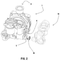
Figure 2 : représentation schématique d'un exemple de pompe selon l'invention ; - la
Figure 3 : représentation schématique de l'exemple de lafigure 2 sous un autre angle de vue ; - la
Figure 4 : représentation schématique de l'exemple desfigures 2 et3 , vu en coupe ; - la
Figure 5 : représentation schématique d'un autre exemple de pompe selon l'invention ; - la
Figure 6 : représentation schématique de l'exemple de lafigure 5 , vu en coupe. - La
figure 1 montre un exemple d'installation hydraulique selon l'invention comprenant une pompe 17 selon l'invention. Dans cet exemple, cette installation hydraulique est une installation de chauffage et de fourniture d'eau chaude. - L'installation comprend un premier circuit 18 et un deuxième circuit 19.
- Le premier circuit 18 est destiné à contenir un premier flux d'eau. Il est connecté à une première entrée 2 de la pompe 17.
- Le deuxième circuit 19 est destiné à contenir un deuxième flux d'eau provenant d'une sortie 3 de la pompe 17. Il est connecté à une deuxième entrée 6 de la pompe 17. L'installation comprend en outre un conduit de dérivation 13 externe à la pompe 17, permettant une dérivation du deuxième flux d'eau de l'installation. Ce conduit de dérivation 13 est connecté à une troisième entrée distincte 7 de la pompe 17.
- Plus précisément, dans l'exemple représenté sur la
figure 1 , le deuxième circuit 19 comprend un premier et un deuxième échangeurs 14, 15 de chaleur. Le conduit de dérivation 13 relie alors le deuxième circuit 19, à partir d'un point situé après la sortie du deuxième échangeur 15, à la troisième entrée 7 de la pompe 19. - Comme on peut également le voir plus en détail sur le exemples des
figures 2 à 6 , la pompe 1 comprend un corps 1, une première entrée 2, une sortie 3, des moyens de circulation 4 d'un fluide, et une vanne 5 présentant trois voies. - Les moyens de circulation 4 sont disposés entre la sortie 3 et une première voie de la vanne 5.
- Par ailleurs, la vanne 5 est reliée par une deuxième voie à la première entrée 2.
- La pompe comprend également une deuxième entrée 6 reliée à une troisième voie de la vanne 5.
- La pompe comprend en outre une troisième entrée 7 distincte reliée aux moyens de circulation 4 par un conduit 8.
- Comme on l'a vu en référence à la
figure 1 , ce conduit 8 permet de conduit un flux dérivé du deuxième circuit 19 de l'installation hydraulique, grâce à un conduit de dérivation externe 13 de l'installation connecté à ce conduit 8 de la pompe par l'intermédiaire de la troisième entrée distincte 7 de cette pompe. - Ce conduit de dérivation externe 13 et le conduit 8 interne à la pompe permettent ainsi de protéger le premier échangeur de chaleur 14 en assurant l'alimentation de ce dernier en eau même lorsque l'alimentation principale en eau de l'installation est fermée alors que l'entrée 2 de la pompe 1 est reliée aux moyens de circulation 4 via la vanne 5.
- En outre, il est possible d'intervenir sur le conduit 8 à l'intérieur de la pompe sans ouvrir le corps 1 de cette pompe, simplement en déconnectant le conduit de dérivation externe 13 dans l'installation de la troisième entrée distincte 7 dans la pompe.
- De préférence, un élément de type clapet anti-retour ou vanne 10 est disposé dans le conduit 8, pour éviter le reflux d'eau vers le deuxième circuit 19 de l'installation.
- Il est ainsi facile d'intervenir sur la pompe pour changer ce clapet anti-retour ou vanne 10, sans ouvrir le corps 1 de la pompe, simplement en y accédant via la troisième entrée distincte 7 de la pompe, après avoir déconnecté le conduit de dérivation externe 13 dans l'installation de cette troisième entrée distincte 7 dans la pompe.
- De préférence, l'installation comprend une interface 16 pour connecter le deuxième circuit 19 à la deuxième entrée 6 de la pompe. Cette interface comprend un premier et un deuxième conduits. Le premier conduit est destiné à relier le deuxième circuit 19 de l'installation avec la deuxième entrée 6 de la pompe. Le deuxième conduit est destiné à relié le conduit de dérivation externe 13 dans l'installation avec la troisième entrée distincte 7 de la pompe.
- Dans l'exemple des
figures 2 à 4 , dans le cas où un élément de type clapet anti-retour ou valve 10 est utilisé comme expliqué plus haut, celui-ci est inséré dans une extrémité du deuxième conduit de l'interface 16 qui elle-même est insérée dans le conduit 8 de la pompe via la troisième entrée distincte 7 de la pompe. - Alternativement, comme représenté sur l'exemple des
figures 5 et 6 , la pompe comprend un module 9 démontable. Ce module 9 peut ainsi être fixé et éventuellement verrouillé dans le corps 1 de la pompe, et être facilement désolidarisé du corps 1 de la pompe après éventuel déverrouillage. - Ce module 9 comprend une portion du conduit 8. Précisément, une partie de ce module 9 forme, une fois celui-ci inséré dans le corps 1 de la pompe, une portion du conduit 8.
- Dans le cas où un élément de type clapet anti-retour ou valve 10 est utilisé comme expliqué plus haut, celui-ci est alors inséré dans cette partie du module 9 qui forme, une fois inséré dans le corps 1 de la pompe, une portion du conduit 8.
- L'insertion du module 9 dans le corps 1 de la pompe s'effectue via une quatrième entrée distincte, fournissant ainsi un autre accès au conduit 8, et au clapet anti-retour ou vanne 10 lorsque présent.
- La présente description est donnée à titre d'exemple et n'est pas limitative de l'invention.
- En particulier, l'invention ne se limite pas à une pompe destinée à une installation hydraulique de chauffage et/ou de fourniture d'eau chaude, ni à une telle installation. Elle s'étend en effet à tout type d'installation hydraulique nécessitant l'utilisation d'une pompe de circulation de l'eau contenue dans l'installation.
Claims (6)
- Pompe destinée à faire circuler de l'eau dans une installation hydraulique, telle qu'une installation de chauffage et/ou de fourniture d'eau chaude, ladite pompe comprenant un corps (1), une première entrée (2), une sortie (3), des moyens de circulation (4) d'un fluide et une vanne (5) présentant trois voies, lesdits moyens de circulation (4) étant disposés entre la sortie (3) et une première voie de ladite vanne (5), ladite vanne (5) étant reliée par une deuxième voie à la première entrée (2), ladite pompe comprenant une deuxième entrée (6) reliée à une troisième voie de ladite vanne (5),
caractérisée en ce que ladite pompe comprend une troisième entrée (7) distincte reliée aux moyens de circulation (4) par un conduit (8). - Pompe selon la revendication 1, caractérisée en ce qu'elle comprend un clapet anti-retour ou une valve (10) disposé dans le conduit (8).
- Pompe selon l'une quelconque des revendications 1 et 2, caractérisée en ce qu'elle comprend un module (9) démontable comprenant une portion du conduit (8).
- Pompe selon les revendications 2 et 3, caractérisée en ce que le clapet anti-retour ou la valve (10) est disposé dans la portion du conduit (9) comprise dans le module (9).
- Installation hydraulique, telle qu'une installation de chauffage et/ou de fourniture d'eau chaude, comprenant une pompe (17) selon l'une quelconque des revendications précédentes, un premier circuit (18) destiné à contenir un premier flux d'eau et connecté à la première entrée (2) de la pompe (17), un deuxième circuit (19), destiné à contenir un deuxième flux d'eau provenant de la sortie (3) de la pompe (17) et connecté à la deuxième entrée (6) de la pompe (17), un conduit de dérivation (13) du deuxième flux d'eau de l'installation étant connecté à la troisième entrée (7) de la pompe (17).
- Installation hydraulique selon la revendication précédente, caractérisée en ce que le deuxième circuit (19) comprend un premier et un deuxième échangeurs (14, 15) de chaleur, le conduit de dérivation (13) reliant le deuxième circuit (17) à partir d'un point situé après la sortie du deuxième échangeur (15), à la troisième entrée (7) de la pompe (19).
Applications Claiming Priority (1)
| Application Number | Priority Date | Filing Date | Title |
|---|---|---|---|
| FR1915481A FR3105312B1 (fr) | 2019-12-23 | 2019-12-23 | Pompe pour installation hydraulique, et installation hydraulique correspondante |
Publications (2)
| Publication Number | Publication Date |
|---|---|
| EP3842696A1 EP3842696A1 (fr) | 2021-06-30 |
| EP3842696B1 true EP3842696B1 (fr) | 2022-03-02 |
Family
ID=69743588
Family Applications (1)
| Application Number | Title | Priority Date | Filing Date |
|---|---|---|---|
| EP20215938.0A Active EP3842696B1 (fr) | 2019-12-23 | 2020-12-21 | Pompe pour installation hydraulique, et installation hydraulique correspondante |
Country Status (2)
| Country | Link |
|---|---|
| EP (1) | EP3842696B1 (fr) |
| FR (1) | FR3105312B1 (fr) |
Family Cites Families (2)
| Publication number | Priority date | Publication date | Assignee | Title |
|---|---|---|---|---|
| ITAN20010008A1 (it) * | 2001-02-07 | 2002-08-07 | Merloni Termosanitari Spa | Caldaia con produzione istantanea di acqua calda perfezionata |
| ITTO20110334A1 (it) * | 2011-04-13 | 2012-10-14 | Elbi Int Spa | Gruppo idraulico di pompaggio per una caldaia per un impianto di riscaldamento e di generazione di acqua calda sanitaria |
-
2019
- 2019-12-23 FR FR1915481A patent/FR3105312B1/fr not_active Expired - Fee Related
-
2020
- 2020-12-21 EP EP20215938.0A patent/EP3842696B1/fr active Active
Also Published As
| Publication number | Publication date |
|---|---|
| FR3105312A1 (fr) | 2021-06-25 |
| EP3842696A1 (fr) | 2021-06-30 |
| FR3105312B1 (fr) | 2021-12-31 |
Similar Documents
| Publication | Publication Date | Title |
|---|---|---|
| EP3227595A1 (fr) | Raccord fluidique coaxial | |
| EP2623835B1 (fr) | Raccord rapide et système de contrôle de température incorporant un tel raccord | |
| EP3842696A1 (fr) | Pompe pour installation hydraulique, et installation hydraulique correspondante | |
| FR2755204A1 (fr) | Dispositif de commande hydraulique pour embrayage de prise directe monte dans un convertisseur de couple | |
| EP0568433A1 (fr) | Dispositif d'évacuation de la puissance résiduelle du coeur d'un réacteur nucléaire à eau pressurisée | |
| EP1972867A1 (fr) | Raccord destiné à raccorder un tube avec une nourrice | |
| FR2787148A1 (fr) | Distributeur hydraulique | |
| EP3599409B1 (fr) | Raccord rapide pour la jonction amovible de deux canalisations parcourues par un fluide sous pression | |
| FR3102826A1 (fr) | Raccord à désaccouplement rapide avec vannes internes | |
| FR2694473A3 (fr) | Four de fusion à induction possédant une partie inférieure amovible. | |
| CN116146705B (zh) | 具有散热功能的液压系统及工程机械车辆 | |
| CN115614654B (zh) | 一种三通回油组件 | |
| FR2543253A1 (fr) | Mitigeur a levier unique a relier a un chauffe-eau a basse pression | |
| EP3537251B1 (fr) | Robinet mitigeur thermostatique | |
| FR2550605A1 (fr) | Bloc de derivation pour circuit hydraulique, notamment de chauffage | |
| EP1607818A1 (fr) | Vanne thermostatistique pour un circuit de refroidissement | |
| WO2006003336A1 (fr) | Systeme de refroidissement pour moteur de véhicule a circuit d'eau et circuit d'huile | |
| US20100282994A1 (en) | Flow Bypass Manifold Including Drain | |
| EP3385142B1 (fr) | Equipement monobloc de traitement d'air d'une voiture, notamment de véhicule ferroviaire, comprenant au moins deux salles | |
| EP2713111B1 (fr) | Module de transfert thermique compact | |
| JP3822705B2 (ja) | 追焚付き給湯装置 | |
| EP0595718B1 (fr) | Vanne pour installation de chauffage à manchon de raccord, installation de chauffage central et radiateur comportant au moins une telle vanne | |
| FR3127540A1 (fr) | Vanne d’arrêt d’écoulement de fluide à élément limiteur amovible | |
| FR2756349A1 (fr) | Distributeur hydraulique avec clapet antiretour | |
| FR3094066A1 (fr) | Conduite de répartition de fluide comprenant un passage principal et des passages secondaires de fluide |
Legal Events
| Date | Code | Title | Description |
|---|---|---|---|
| PUAI | Public reference made under article 153(3) epc to a published international application that has entered the european phase |
Free format text: ORIGINAL CODE: 0009012 |
|
| STAA | Information on the status of an ep patent application or granted ep patent |
Free format text: STATUS: THE APPLICATION HAS BEEN PUBLISHED |
|
| AK | Designated contracting states |
Kind code of ref document: A1 Designated state(s): AL AT BE BG CH CY CZ DE DK EE ES FI FR GB GR HR HU IE IS IT LI LT LU LV MC MK MT NL NO PL PT RO RS SE SI SK SM TR |
|
| STAA | Information on the status of an ep patent application or granted ep patent |
Free format text: STATUS: REQUEST FOR EXAMINATION WAS MADE |
|
| 17P | Request for examination filed |
Effective date: 20210729 |
|
| RBV | Designated contracting states (corrected) |
Designated state(s): AL AT BE BG CH CY CZ DE DK EE ES FI FR GB GR HR HU IE IS IT LI LT LU LV MC MK MT NL NO PL PT RO RS SE SI SK SM TR |
|
| RIC1 | Information provided on ipc code assigned before grant |
Ipc: F04C 14/26 20060101ALN20210909BHEP Ipc: F04C 15/06 20060101ALN20210909BHEP Ipc: F24H 9/14 20060101ALI20210909BHEP Ipc: F24D 19/10 20060101ALI20210909BHEP Ipc: F24D 3/10 20060101AFI20210909BHEP |
|
| GRAP | Despatch of communication of intention to grant a patent |
Free format text: ORIGINAL CODE: EPIDOSNIGR1 |
|
| STAA | Information on the status of an ep patent application or granted ep patent |
Free format text: STATUS: GRANT OF PATENT IS INTENDED |
|
| INTG | Intention to grant announced |
Effective date: 20211026 |
|
| GRAS | Grant fee paid |
Free format text: ORIGINAL CODE: EPIDOSNIGR3 |
|
| GRAA | (expected) grant |
Free format text: ORIGINAL CODE: 0009210 |
|
| STAA | Information on the status of an ep patent application or granted ep patent |
Free format text: STATUS: THE PATENT HAS BEEN GRANTED |
|
| AK | Designated contracting states |
Kind code of ref document: B1 Designated state(s): AL AT BE BG CH CY CZ DE DK EE ES FI FR GB GR HR HU IE IS IT LI LT LU LV MC MK MT NL NO PL PT RO RS SE SI SK SM TR |
|
| REG | Reference to a national code |
Ref country code: GB Ref legal event code: FG4D Free format text: NOT ENGLISH |
|
| REG | Reference to a national code |
Ref country code: CH Ref legal event code: EP Ref country code: AT Ref legal event code: REF Ref document number: 1472539 Country of ref document: AT Kind code of ref document: T Effective date: 20220315 |
|
| REG | Reference to a national code |
Ref country code: DE Ref legal event code: R096 Ref document number: 602020002059 Country of ref document: DE |
|
| REG | Reference to a national code |
Ref country code: IE Ref legal event code: FG4D Free format text: LANGUAGE OF EP DOCUMENT: FRENCH |
|
| REG | Reference to a national code |
Ref country code: NL Ref legal event code: FP |
|
| REG | Reference to a national code |
Ref country code: LT Ref legal event code: MG9D |
|
| PG25 | Lapsed in a contracting state [announced via postgrant information from national office to epo] |
Ref country code: SE Free format text: LAPSE BECAUSE OF FAILURE TO SUBMIT A TRANSLATION OF THE DESCRIPTION OR TO PAY THE FEE WITHIN THE PRESCRIBED TIME-LIMIT Effective date: 20220302 Ref country code: RS Free format text: LAPSE BECAUSE OF FAILURE TO SUBMIT A TRANSLATION OF THE DESCRIPTION OR TO PAY THE FEE WITHIN THE PRESCRIBED TIME-LIMIT Effective date: 20220302 Ref country code: NO Free format text: LAPSE BECAUSE OF FAILURE TO SUBMIT A TRANSLATION OF THE DESCRIPTION OR TO PAY THE FEE WITHIN THE PRESCRIBED TIME-LIMIT Effective date: 20220602 Ref country code: LT Free format text: LAPSE BECAUSE OF FAILURE TO SUBMIT A TRANSLATION OF THE DESCRIPTION OR TO PAY THE FEE WITHIN THE PRESCRIBED TIME-LIMIT Effective date: 20220302 Ref country code: HR Free format text: LAPSE BECAUSE OF FAILURE TO SUBMIT A TRANSLATION OF THE DESCRIPTION OR TO PAY THE FEE WITHIN THE PRESCRIBED TIME-LIMIT Effective date: 20220302 Ref country code: ES Free format text: LAPSE BECAUSE OF FAILURE TO SUBMIT A TRANSLATION OF THE DESCRIPTION OR TO PAY THE FEE WITHIN THE PRESCRIBED TIME-LIMIT Effective date: 20220302 Ref country code: BG Free format text: LAPSE BECAUSE OF FAILURE TO SUBMIT A TRANSLATION OF THE DESCRIPTION OR TO PAY THE FEE WITHIN THE PRESCRIBED TIME-LIMIT Effective date: 20220602 |
|
| REG | Reference to a national code |
Ref country code: AT Ref legal event code: MK05 Ref document number: 1472539 Country of ref document: AT Kind code of ref document: T Effective date: 20220302 |
|
| PG25 | Lapsed in a contracting state [announced via postgrant information from national office to epo] |
Ref country code: PL Free format text: LAPSE BECAUSE OF FAILURE TO SUBMIT A TRANSLATION OF THE DESCRIPTION OR TO PAY THE FEE WITHIN THE PRESCRIBED TIME-LIMIT Effective date: 20220302 Ref country code: LV Free format text: LAPSE BECAUSE OF FAILURE TO SUBMIT A TRANSLATION OF THE DESCRIPTION OR TO PAY THE FEE WITHIN THE PRESCRIBED TIME-LIMIT Effective date: 20220302 Ref country code: GR Free format text: LAPSE BECAUSE OF FAILURE TO SUBMIT A TRANSLATION OF THE DESCRIPTION OR TO PAY THE FEE WITHIN THE PRESCRIBED TIME-LIMIT Effective date: 20220603 Ref country code: FI Free format text: LAPSE BECAUSE OF FAILURE TO SUBMIT A TRANSLATION OF THE DESCRIPTION OR TO PAY THE FEE WITHIN THE PRESCRIBED TIME-LIMIT Effective date: 20220302 |
|
| PG25 | Lapsed in a contracting state [announced via postgrant information from national office to epo] |
Ref country code: SM Free format text: LAPSE BECAUSE OF FAILURE TO SUBMIT A TRANSLATION OF THE DESCRIPTION OR TO PAY THE FEE WITHIN THE PRESCRIBED TIME-LIMIT Effective date: 20220302 Ref country code: SK Free format text: LAPSE BECAUSE OF FAILURE TO SUBMIT A TRANSLATION OF THE DESCRIPTION OR TO PAY THE FEE WITHIN THE PRESCRIBED TIME-LIMIT Effective date: 20220302 Ref country code: RO Free format text: LAPSE BECAUSE OF FAILURE TO SUBMIT A TRANSLATION OF THE DESCRIPTION OR TO PAY THE FEE WITHIN THE PRESCRIBED TIME-LIMIT Effective date: 20220302 Ref country code: PT Free format text: LAPSE BECAUSE OF FAILURE TO SUBMIT A TRANSLATION OF THE DESCRIPTION OR TO PAY THE FEE WITHIN THE PRESCRIBED TIME-LIMIT Effective date: 20220704 Ref country code: EE Free format text: LAPSE BECAUSE OF FAILURE TO SUBMIT A TRANSLATION OF THE DESCRIPTION OR TO PAY THE FEE WITHIN THE PRESCRIBED TIME-LIMIT Effective date: 20220302 Ref country code: CZ Free format text: LAPSE BECAUSE OF FAILURE TO SUBMIT A TRANSLATION OF THE DESCRIPTION OR TO PAY THE FEE WITHIN THE PRESCRIBED TIME-LIMIT Effective date: 20220302 Ref country code: AT Free format text: LAPSE BECAUSE OF FAILURE TO SUBMIT A TRANSLATION OF THE DESCRIPTION OR TO PAY THE FEE WITHIN THE PRESCRIBED TIME-LIMIT Effective date: 20220302 |
|
| PG25 | Lapsed in a contracting state [announced via postgrant information from national office to epo] |
Ref country code: IS Free format text: LAPSE BECAUSE OF FAILURE TO SUBMIT A TRANSLATION OF THE DESCRIPTION OR TO PAY THE FEE WITHIN THE PRESCRIBED TIME-LIMIT Effective date: 20220702 Ref country code: AL Free format text: LAPSE BECAUSE OF FAILURE TO SUBMIT A TRANSLATION OF THE DESCRIPTION OR TO PAY THE FEE WITHIN THE PRESCRIBED TIME-LIMIT Effective date: 20220302 |
|
| REG | Reference to a national code |
Ref country code: DE Ref legal event code: R097 Ref document number: 602020002059 Country of ref document: DE |
|
| PLBE | No opposition filed within time limit |
Free format text: ORIGINAL CODE: 0009261 |
|
| STAA | Information on the status of an ep patent application or granted ep patent |
Free format text: STATUS: NO OPPOSITION FILED WITHIN TIME LIMIT |
|
| PG25 | Lapsed in a contracting state [announced via postgrant information from national office to epo] |
Ref country code: DK Free format text: LAPSE BECAUSE OF FAILURE TO SUBMIT A TRANSLATION OF THE DESCRIPTION OR TO PAY THE FEE WITHIN THE PRESCRIBED TIME-LIMIT Effective date: 20220302 |
|
| 26N | No opposition filed |
Effective date: 20221205 |
|
| REG | Reference to a national code |
Ref country code: BE Ref legal event code: MM Effective date: 20221231 |
|
| PG25 | Lapsed in a contracting state [announced via postgrant information from national office to epo] |
Ref country code: LU Free format text: LAPSE BECAUSE OF NON-PAYMENT OF DUE FEES Effective date: 20221221 |
|
| PG25 | Lapsed in a contracting state [announced via postgrant information from national office to epo] |
Ref country code: IE Free format text: LAPSE BECAUSE OF NON-PAYMENT OF DUE FEES Effective date: 20221221 |
|
| PG25 | Lapsed in a contracting state [announced via postgrant information from national office to epo] |
Ref country code: BE Free format text: LAPSE BECAUSE OF NON-PAYMENT OF DUE FEES Effective date: 20221231 |
|
| PG25 | Lapsed in a contracting state [announced via postgrant information from national office to epo] |
Ref country code: CY Free format text: LAPSE BECAUSE OF FAILURE TO SUBMIT A TRANSLATION OF THE DESCRIPTION OR TO PAY THE FEE WITHIN THE PRESCRIBED TIME-LIMIT Effective date: 20220302 |
|
| PG25 | Lapsed in a contracting state [announced via postgrant information from national office to epo] |
Ref country code: MK Free format text: LAPSE BECAUSE OF FAILURE TO SUBMIT A TRANSLATION OF THE DESCRIPTION OR TO PAY THE FEE WITHIN THE PRESCRIBED TIME-LIMIT Effective date: 20220302 |
|
| PG25 | Lapsed in a contracting state [announced via postgrant information from national office to epo] |
Ref country code: MC Free format text: LAPSE BECAUSE OF FAILURE TO SUBMIT A TRANSLATION OF THE DESCRIPTION OR TO PAY THE FEE WITHIN THE PRESCRIBED TIME-LIMIT Effective date: 20220302 |
|
| PG25 | Lapsed in a contracting state [announced via postgrant information from national office to epo] |
Ref country code: MC Free format text: LAPSE BECAUSE OF FAILURE TO SUBMIT A TRANSLATION OF THE DESCRIPTION OR TO PAY THE FEE WITHIN THE PRESCRIBED TIME-LIMIT Effective date: 20220302 |
|
| REG | Reference to a national code |
Ref country code: CH Ref legal event code: PL |
|
| PG25 | Lapsed in a contracting state [announced via postgrant information from national office to epo] |
Ref country code: MT Free format text: LAPSE BECAUSE OF FAILURE TO SUBMIT A TRANSLATION OF THE DESCRIPTION OR TO PAY THE FEE WITHIN THE PRESCRIBED TIME-LIMIT Effective date: 20220302 |
|
| PG25 | Lapsed in a contracting state [announced via postgrant information from national office to epo] |
Ref country code: CH Free format text: LAPSE BECAUSE OF NON-PAYMENT OF DUE FEES Effective date: 20231231 |
|
| PG25 | Lapsed in a contracting state [announced via postgrant information from national office to epo] |
Ref country code: CH Free format text: LAPSE BECAUSE OF NON-PAYMENT OF DUE FEES Effective date: 20231231 |
|
| PG25 | Lapsed in a contracting state [announced via postgrant information from national office to epo] |
Ref country code: HU Free format text: LAPSE BECAUSE OF FAILURE TO SUBMIT A TRANSLATION OF THE DESCRIPTION OR TO PAY THE FEE WITHIN THE PRESCRIBED TIME-LIMIT; INVALID AB INITIO Effective date: 20201221 |
|
| PG25 | Lapsed in a contracting state [announced via postgrant information from national office to epo] |
Ref country code: TR Free format text: LAPSE BECAUSE OF FAILURE TO SUBMIT A TRANSLATION OF THE DESCRIPTION OR TO PAY THE FEE WITHIN THE PRESCRIBED TIME-LIMIT Effective date: 20220302 |
|
| PGFP | Annual fee paid to national office [announced via postgrant information from national office to epo] |
Ref country code: GB Payment date: 20251224 Year of fee payment: 6 |
|
| PGFP | Annual fee paid to national office [announced via postgrant information from national office to epo] |
Ref country code: FR Payment date: 20251217 Year of fee payment: 6 Ref country code: NL Payment date: 20251230 Year of fee payment: 6 |
|
| PG25 | Lapsed in a contracting state [announced via postgrant information from national office to epo] |
Ref country code: SI Free format text: LAPSE BECAUSE OF FAILURE TO SUBMIT A TRANSLATION OF THE DESCRIPTION OR TO PAY THE FEE WITHIN THE PRESCRIBED TIME-LIMIT Effective date: 20220302 |
|
| PGFP | Annual fee paid to national office [announced via postgrant information from national office to epo] |
Ref country code: DE Payment date: 20251222 Year of fee payment: 6 |
|
| PGFP | Annual fee paid to national office [announced via postgrant information from national office to epo] |
Ref country code: IT Payment date: 20251230 Year of fee payment: 6 |