EP3537251B1 - Robinet mitigeur thermostatique - Google Patents
Robinet mitigeur thermostatique Download PDFInfo
- Publication number
- EP3537251B1 EP3537251B1 EP19161047.6A EP19161047A EP3537251B1 EP 3537251 B1 EP3537251 B1 EP 3537251B1 EP 19161047 A EP19161047 A EP 19161047A EP 3537251 B1 EP3537251 B1 EP 3537251B1
- Authority
- EP
- European Patent Office
- Prior art keywords
- cold water
- water inlet
- hot water
- tube
- shuttle
- Prior art date
- Legal status (The legal status is an assumption and is not a legal conclusion. Google has not performed a legal analysis and makes no representation as to the accuracy of the status listed.)
- Active
Links
- XLYOFNOQVPJJNP-UHFFFAOYSA-N water Substances O XLYOFNOQVPJJNP-UHFFFAOYSA-N 0.000 claims description 159
- 239000002775 capsule Substances 0.000 claims description 7
- 229920002994 synthetic fiber Polymers 0.000 claims description 2
- 238000004519 manufacturing process Methods 0.000 description 6
- 239000000543 intermediate Substances 0.000 description 3
- 230000000903 blocking effect Effects 0.000 description 2
- 238000001125 extrusion Methods 0.000 description 2
- 230000002093 peripheral effect Effects 0.000 description 2
- 230000015556 catabolic process Effects 0.000 description 1
- 239000002131 composite material Substances 0.000 description 1
- 238000006731 degradation reaction Methods 0.000 description 1
- 238000000605 extraction Methods 0.000 description 1
- 238000002347 injection Methods 0.000 description 1
- 239000007924 injection Substances 0.000 description 1
- 238000009434 installation Methods 0.000 description 1
- 230000001105 regulatory effect Effects 0.000 description 1
- 230000000284 resting effect Effects 0.000 description 1
- 238000007789 sealing Methods 0.000 description 1
Images


Classifications
-
- G—PHYSICS
- G05—CONTROLLING; REGULATING
- G05D—SYSTEMS FOR CONTROLLING OR REGULATING NON-ELECTRIC VARIABLES
- G05D23/00—Control of temperature
- G05D23/01—Control of temperature without auxiliary power
- G05D23/13—Control of temperature without auxiliary power by varying the mixing ratio of two fluids having different temperatures
- G05D23/1306—Control of temperature without auxiliary power by varying the mixing ratio of two fluids having different temperatures for liquids
- G05D23/132—Control of temperature without auxiliary power by varying the mixing ratio of two fluids having different temperatures for liquids with temperature sensing element
- G05D23/134—Control of temperature without auxiliary power by varying the mixing ratio of two fluids having different temperatures for liquids with temperature sensing element measuring the temperature of mixed fluid
- G05D23/1346—Control of temperature without auxiliary power by varying the mixing ratio of two fluids having different temperatures for liquids with temperature sensing element measuring the temperature of mixed fluid with manual temperature setting means
- G05D23/1353—Control of temperature without auxiliary power by varying the mixing ratio of two fluids having different temperatures for liquids with temperature sensing element measuring the temperature of mixed fluid with manual temperature setting means combined with flow controlling means
-
- F—MECHANICAL ENGINEERING; LIGHTING; HEATING; WEAPONS; BLASTING
- F16—ENGINEERING ELEMENTS AND UNITS; GENERAL MEASURES FOR PRODUCING AND MAINTAINING EFFECTIVE FUNCTIONING OF MACHINES OR INSTALLATIONS; THERMAL INSULATION IN GENERAL
- F16K—VALVES; TAPS; COCKS; ACTUATING-FLOATS; DEVICES FOR VENTING OR AERATING
- F16K11/00—Multiple-way valves, e.g. mixing valves; Pipe fittings incorporating such valves
- F16K11/02—Multiple-way valves, e.g. mixing valves; Pipe fittings incorporating such valves with all movable sealing faces moving as one unit
- F16K11/04—Multiple-way valves, e.g. mixing valves; Pipe fittings incorporating such valves with all movable sealing faces moving as one unit comprising only lift valves
- F16K11/044—Multiple-way valves, e.g. mixing valves; Pipe fittings incorporating such valves with all movable sealing faces moving as one unit comprising only lift valves with movable valve members positioned between valve seats
- F16K11/0445—Bath/shower selectors
Definitions
- the present invention relates to a thermostatic mixing valve without a non-return valve for distributing water in sanitary installations such as showers, washbasins or sinks.
- a thermostatic mixing valve comprises a body of elongated cylindrical shape with, towards one of its ends, a hot water inlet and a hot water opening control and, towards its other end, a hot water inlet. cold water and a mixed water temperature adjustment device.
- Such a thermostatic mixing valve body also includes a mixed water outlet arranged more towards the cold water inlet.
- mixers in particular the model according to the document FR3013417 which includes a mixer cartridge with a socket.
- the mixing valve disclosed in this document is defined according to the characteristics of the preamble of claim 1.
- This socket has internal grooves which receive radial slots to supply hot water and cold water respectively.
- This socket also contains a shuttle or drawer, the longitudinal position of which is controlled by a thermostatic cell containing wax.
- the document DE 102 28 212 A1 discloses a conventional valve for a mixing valve.
- the present invention is an improvement to this type of mixer.
- An idea underlying the invention is to allow better stability of the mixed water temperature and a significant reduction in manufacturing costs.
- An idea underlying the invention is also to provide a mixer which is simple to manufacture.
- An idea underlying the invention is also to provide a mixing valve having good wear resistance characteristics.
- An idea underlying the invention is also to provide such a mixer which is easy to maintain by being easily removable.
- the invention provides a thermostatic mixing valve having a water opening control located on the hot water inlet side and a temperature adjustment control located on the water supply side. cold water inlet, said mixing valve comprising a mixed water outlet located on the side of the cold water inlet, which is characterized in that the mechanism of this mixing valve comprises a head body screwed into the body of the mixing valve, said head body being extended by a tube which passes through a ring located at the level of the mixed water outlet, said tube terminating in a sleeve which brings hot water from the inlet of hot water, and in that the tube receives a plug also located in the sleeve, a flat hot water inlet seat being located in the plug and a flat cold water inlet seat located in the tube integral with the head body, a shuttle receiving a wax capsule being slidably mounted inside the tube, said shuttle carrying the hot water and cold water valves cooperating with said respectively flat hot water inlet seat and seat cold water inlet dish, and in that the tube has, at the inlet of
- the mixing valve according to the invention is easy to manufacture.
- such a mixing valve makes it possible to house the shuttle in the tube with the cold water valve facing the flat cold water inlet seat and then, by mounting the cap on the tube, to bring the flat seat back to the tube. hot water inlet carried by the cap opposite the hot water valve.
- a shuttle is easy to mount in the head body and does not require force-mounting, limiting the risks of degradation of the valves during assembly of the shuttle in the tube.
- Such a shuttle is also easy to remove, for example in the context of replacing the shuttle or seals carried by the shuttle, since it suffices to remove the plug so that one end of the shuttle is easily accessible for the extraction of the shuttle.
- such a thermostatic mixing valve can have one or more of the following characteristics:
- the shuttle receives two flat gaskets respectively forming a valve for hot water and a valve for cold water and cooperating respectively with the flat hot water inlet seat and the flat inlet seat of Cold water.
- the plug has one or more radial slots formed facing the hot water inlet seat.
- the assembly of the shuttle in the tube followed by the assembly of the cap on the tube offers greater freedom of manufacture of said valves and valve seats.
- This freedom of manufacture makes it possible to produce hot and cold water seats in a flat shape, the surface of which cooperates with the valves is perpendicular to the sliding axis of the shuttle.
- the use of such flat gaskets and flat seats to form the valves and the valve seats allows better cooperation between the flat valves and the flat seats and therefore better operation of the mixing valve.
- flat gaskets and flat valve seats allow better sealing and therefore better stability of the mixed water temperature.
- Such seals also degrade little during the movements of the shuttle during use and, in the event of a drop in cold water pressure, the flat valve ensures perfect closure of the flat inlet seat of the valve. hot water, which guarantees perfect anti-scalding safety for the user.
- the head body and the tube are made in one piece, preferably molded from synthetic materials.
- the tube and the stopper are made integral by a thread.
- the shuttle is formed in a single part with five peripheral grooves for receiving seals, including a first O-ring on the mixed water outlet side, said first O-ring cooperating with the second bore of the tube to prevent direct passage. cold water to the outlet, a second O-ring between the cold and hot water inlet slots to prevent intercommunication, and a third O-ring next to the plug, beyond the arrival of hot water, to ensure the centering of the shuttle in said stopper, the flat valves being arranged in the intermediate grooves; said shuttle comprising on the one hand one or more radial slots for the passage of hot water, said slots being arranged between the hot water valve and the third O-ring located on the shuttle opposite the stopper, and on the other apart from one or two radial slots for the passage of cold water, said slots being arranged between the cold water valve and the first O-ring located on the shuttle to the downstream part, on the mixed water outlet side.
- the shuttle consists of three nested parts, a central part receiving a first end part and a second end part, the hot water valve being interposed between the central part and the first part. end and the cold water valve being interposed between the central part and the second end part so that the mounting of the first end part and of the second end part on the central part makes it possible to trap the hot and cold water valves.
- Such a shuttle is simple to produce, in particular such a shuttle makes it possible to form housings for the flat gaskets in a simple manner and thus to make them prisoners to prevent any risk of extrusion.
- the end portions of the shuttle have radial hot water inlet and cold water inlet slots located on either side of the valves.
- the tube comprises one or more radial slots located downstream of the shuttle opposite a ring whose internal channel makes it possible to conduct the mixed water towards the outlet of the mixing valve.
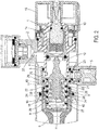
- the figure 1 illustrates a thermostatic mixing valve mechanism comprising a body of elongated cylindrical shape with, towards one of its ends, a hot water inlet 7 and a control for opening the hot water and, towards its other end, a cold water inlet 32 and a component for adjusting the temperature of the mixed water.
- a thermostatic mixing valve body also comprises a mixed water outlet 5 arranged rather towards the arrival of cold water 32.
- the mixed water outlet from the mixing valve is shown in the same plan as the hot and cold water inlets from the mixing valve.
- the mixed water outlet could be arranged differently, for example orthogonally to the hot and cold water inlets.
- This thermostatic mixing valve comprises a head body 1 screwed into the body of the mixing valve 2, which head body 1 is extended through the tube 3.
- said head body 1 and said tube 3 are made in one piece, preferably by injection of composite materials, which has the advantage of perfect dimensional control and low production cost.
- the tube 3 passes through a ring 4 housed in the body of the mixer 2 and located at the level of the mixed water outlet 5.
- the tube 3 ends in a sleeve 6, housed in the body of the mixer 2, which brings hot water from a hot water inlet 7 from the thermostatic mixing valve.
- the tube 3 receives a plug 8 also located in the sleeve 6.
- the tube 3 and the plug 8 are made integral by a thread 9 or any other means, for example by clipping, bayonet system or the like.
- a shuttle 10 is slidably mounted inside the tube 3 and the stopper 8.
- This shuttle 10 receives a capsule 11 containing wax which contracts or expands more or less depending on the temperature of the water circulating in the shuttle 10.
- the capsule 11 cooperates with a piston 12, said piston 12 cooperating with the member. regulating temperature composed of the control rod 13, the temperature limitation stopper 14 and the temperature adjustment handwheel 15 located at the outer end of the control rod 13.
- the principle of cooperation between the capsule 11 and the shuttle 10 making it possible to move the shuttle 10 is for example described in the document FR3013417 .
- the shuttle 10 receives two flat seals, a first flat seal 16 forming a valve for hot water and a second flat seal 17 forming a valve for cold water.
- a first flat seal 16 forming a valve for hot water
- a second flat seal 17 forming a valve for cold water.
- flat gaskets have a parallelepipedal section and have a slight radius on their outer edges.
- the stopper 8 comprises a flat hot water inlet seat 18 cooperating with the first flat gasket 16.
- the tube 3 integral with the head body 1 comprises a flat cold water inlet seat 19 and cooperating with the second flat gasket. 17.
- the tube 3 has, at the entrance to its internal part on the stopper side 8, a first bore 20 dimensioned so as to allow the second seal to pass freely. flat 17, then a second smaller bore 21, the bottom of the first bore 20 forming a shoulder which is the flat cold water inlet seat 19 of the mixing valve opposite the cold water valve, one or more radial slots 22 being made in said tube 3 facing said flat cold water inlet seat 19.
- the mounting of the shuttle 10 in the tube 3 allows the cold water valve 17 to be introduced without constraint opposite the flat cold water inlet seat 19 and the mounting of the plug 8 on the tube 3 makes it possible to bring the flat hot water inlet seat 18 directly opposite the hot water valve 16.
- the tube 3 further comprises one or more slots 23 located downstream of the shuttle 10 opposite the ring 4, the internal channel of which thus makes it possible to conduct the mixed water towards the outlet 5.
- the cold water coming from the cold water inlet 32 penetrates inside the body 2 and flows between said body 2 and the ring 4 through a passage provided for this purpose, and can thus gain the radial slots 22 made in the tube 3.
- One or more radial slots 24 are made in the plug 8 facing the hot water inlet seat 18.
- the shuttle 10 is formed in a single part with five peripheral grooves to receive the seals, including a first O-ring 25 on the mixed water outlet side, the said first O-ring 25 cooperating with the second bore 21 of the tube 3 to prevent direct passage cold water to the outlet, a second O-ring 26 cooperating with the first bore 20 of the tube 3 and located between the inlet slots for cold water 22 and hot water 24 to prevent intercommunication, and a third O-ring 27 is located inside the plug 8, beyond the hot water inlet seat 18, to ensure the centering of the shuttle 10 in said plug 8, the flat valves 16, 17 being arranged in the intermediate grooves; said shuttle 10 comprising on the one hand one or more radial slots 28 for the passage of hot water, said slots 28 being arranged between the hot water valve 16 and the third O-ring 27 located on the shuttle 10 facing the plug 8, and on the other hand one or two radial slots 29 for the passage of cold water, said slots 29 being arranged between the cold water valve 17 and the first O-ring 25
- the radial hot water inlet 28 and cold water inlet 29 slits open into a hollow internal space of the shuttle 10 surrounding the wax cartridge 11. This hollow internal space opens into the tube 3 and allows the mixing of the hot water arriving through the radial hot water inlet slot (s) 28 and the cold water arriving through the radial inlet slot (s) d. cold water 29.
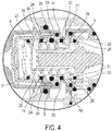
- the figure 4 illustrates an alternative embodiment of the shuttle 10 in which the body of the shuttle is made in 3 nested parts.
- a central part 30 receiving two rings 31 forming the end parts 31 of the shuttle 10.
- a means such as a thread, or a clipping system allowing a permanent connection of the three parts 30, 31 of the shuttle 10.
- the grooves intermediates of the shuttle 10 in which the flat gaskets forming the hot water 16 and cold water 17 valves are housed are advantageously formed by cooperation between the central part 30 and the end parts 31.
- This arrangement has the advantage of allow controlled tightening of the flat gaskets and thus make them prisoners, which avoids the phenomena of vibration and extrusion in the event of high pressures of hot water and / or cold water.
- the central part 30 of the shuttle 10 receives the second O-ring 26 located between the flat seals.
- This second O-ring 26 slides with the shuttle 10 in the tube 3 to avoid intercommunication between the hot water coming from the slots 24 and the cold water coming from the slots 22.
- the wax capsule 11 is housed in the tube 3 resting against the shuttle 10 and allows the shuttle 10 to be moved in the tube according to its state of expansion.
- the movement of the shuttle 10 in the tube 3 causes the valves 16, 17 to cooperate with the corresponding flat seats 18, 19 and to allow a greater or lesser quantity of hot water and / or cold water to enter. the internal space of the shuttle, depending on the position of the shuttle 10 in the tube 3.
- FIG 2 illustrates a state of total opening of the cold water inlet in which the cold water valve 17 is away from the flat cold water inlet seat 19, allowing the arrival of cold water in the internal space of the shuttle 10, and in which the hot water valve 16 bears against the flat hot water inlet seat 18 blocking the arrival of hot water in the internal space of the shuttle 10.
- the figure 3 illustrates a state of total opening of the hot water inlet in which the cold water valve 17 rests against the flat cold water inlet seat 19, blocking the cold water inlet in the 'internal space of the shuttle 10, and in which the hot water valve 16 is remote from the flat hot water inlet seat 18 allowing the arrival of hot water in the internal space of the shuttle 10.
Landscapes
- Engineering & Computer Science (AREA)
- General Engineering & Computer Science (AREA)
- Mechanical Engineering (AREA)
- Physics & Mathematics (AREA)
- General Physics & Mathematics (AREA)
- Automation & Control Theory (AREA)
- Multiple-Way Valves (AREA)
- Domestic Plumbing Installations (AREA)
- Temperature-Responsive Valves (AREA)
Description
- La présente invention concerne un robinet mitigeur thermostatique sans clapet anti retour pour distribuer de l'eau dans les installations sanitaires telles que douches, lavabo ou évier. Un tel robinet mitigeur thermostatique comporte un corps de forme cylindrique allongée avec, vers l'une de ses extrémités, une arrivée d'eau chaude et une commande d'ouverture de l'eau chaude et, vers son autre extrémité, une arrivée d'eau froide et un organe de réglage de la température de l'eau mitigée. Un tel corps de robinet mitigeur thermostatique comporte également une sortie d'eau mitigée disposée plutôt vers l'arrivée de l'eau froide.
- On connait de tels mitigeurs, notamment le modèle selon le document
FR3013417 - Le document
DE 102 28 212 A1 divulgue une vanne classique pour robinet mitigeur. - La présente invention est un perfectionnement à ce type de mitigeur.
- Une idée à la base de l'invention est de permettre une meilleure stabilité de la température d'eau mitigée et une diminution importante des coûts de fabrication. Une idée à la base de l'invention est également de fournir un mitigeur qui soit simple à fabriquer. Une idée à la base de l'invention est aussi de fournir un mitigeur présentant de bonnes caractéristiques de résistance à l'usure. Une idée à la base de l'invention est également de fournir un tel mitigeur qui soit simple d'entretien en étant facilement démontable.
- Pour cela, l'invention fournit un robinet mitigeur thermostatique disposant d'une commande d'ouverture de l'eau située du côté de l'arrivée de l'eau chaude et d'une commande de réglage de température située du côté de l'arrivée de l'eau froide, ledit robinet mitigeur comportant une sortie d'eau mitigée située du côté de l'arrivée de l'eau froide, qui est caractérisé en ce que le mécanisme de ce robinet mitigeur comprend un corps de tête vissé dans le corps du robinet mitigeur, le dit corps de tête se prolongeant par un tube qui traverse une bague située au niveau de la sortie d'eau mitigée, ledit tube aboutissant dans un manchon qui amène l'eau chaude depuis l'arrivée d'eau chaude, et en ce que le tube reçoit un bouchon situé lui aussi dans le manchon, un siège plat d'arrivée d'eau chaude étant situé dans le bouchon et un siège plat d'arrivée d'eau froide situé dans le tube solidaire du corps de tête, une navette recevant une capsule de cire étant montée coulissante à l'intérieur du tube, la dite navette portant les clapets eau chaude et eau froide coopérant avec les dits respectivement siège plat d'arrivée d'eau chaude et siège plat d'arrivée d'eau froide, et en ce que le tube présente, à l'entrée de sa partie interne côté bouchon, un premier alésage dimensionné de manière à laisser passer librement le clapet d'eau froide, puis un deuxième alésage plus petit, le fond du premier alésage formant un épaulement qui est le siège plat d'arrivée d'eau froide du mitigeur en regard du clapet eau froide, une ou plusieurs fentes radiales étant ménagées dans le dit tube en regard du dit siège eau froide.
- Grâce à ces caractéristiques, le robinet mitigeur selon l'invention est simple à fabriquer. En particulier, un tel robinet mitigeur permet de loger la navette dans le tube avec le clapet d'eau froide en regard du siège plat d'arrivée d'eau froide puis, en montant le bouchon sur le tube, de ramener le siège plat d'arrivée d'eau chaude porté par le bouchon en regard du clapet d'eau chaude. Ainsi, une telle navette est simple à monter dans le corps de tête et ne nécessite pas de montage en force, limitant les risques de dégradation des clapets lors du montage de la navette dans le tube.
- Une telle navette est en outre simple à retirer, par exemple dans le cadre d'un remplacement de la navette ou de joints portés par la navette, puisqu'il suffit de retirer le bouchon pour qu'une extrémité de la navette soit facilement accessible pour l'extraction de la navette.
- Selon d'autres modes de réalisation avantageux, un tel robinet mitigeur thermostatique peut présenter une ou plusieurs des caractéristiques suivantes :
Selon un mode de réalisation, la navette reçoit deux joints plats faisant respectivement clapet pour l'eau chaude et clapet pour l'eau froide et coopérant respectivement avec le siège plat d'arrivée d'eau chaude et le siège plat d'arrivée d'eau froide. - Selon un mode de réalisation, le bouchon comporte une ou plusieurs fentes radiales ménagées en regard du siège d'arrivée d'eau chaude.
- Le montage de la navette dans le tube suivi du montage du bouchon sur le tube offre une plus grande liberté de fabrication desdits clapets et sièges de clapets. Cette liberté de fabrication permet de réaliser des sièges eau chaude et eau froide de forme plate dont la surface de coopération avec les clapets est perpendiculaire à l'axe de coulissement de la navette. L'utilisation de tels joints plats et sièges plats pour former les clapets et les sièges de clapet permet une meilleure coopération entre les clapets plats et les sièges plats et donc un meilleur fonctionnement du robinet mitigeur. En particulier, de tels joints plats et sièges de clapets plats permettent une meilleure étanchéité et donc une meilleure stabilité de la température d'eau mitigée. De tels joints se dégradent en outre peu lors des déplacements de la navette en cours d'utilisation et, en cas de chute de pression de l'eau froide, le clapet plat permet d'assurer une fermeture parfaite du siège plat d'arrivée de l'eau chaude, ce qui garantit une parfaite sécurité anti-brulure pour l'usager.
- Selon un mode de réalisation, le corps de tête et le tube sont réalisés en une seule pièce, de préférence moulée en matériaux de synthèse.
- Selon un mode de réalisation, le tube et le bouchon sont rendus solidaires par un filetage.
- Selon un mode de réalisation, la navette est constituée en une seule partie avec cinq gorges périphériques pour recevoir des joints, dont un premier joint torique côté sortie eau mitigée, le dit premier joint torique coopérant avec le deuxième alésage du tube pour empêcher le passage direct de l'eau froide vers la sortie, un deuxième joint torique entre les fentes d'arrivée de l'eau froide et de l'eau chaude pour empêcher l'intercommunication, et un troisième joint torique en regard du bouchon, au-delà de l'arrivée de l'eau chaude, pour assurer le centrage de la navette dans le dit bouchon, les clapets plats étant disposés dans les gorges intermédiaires; la dite navette comportant d'une part une ou des fentes radiales pour le passage de l'eau chaude, les dites fentes étant disposées entre le clapet eau chaude et le troisième joint torique situé sur la navette en regard du bouchon, et d'autre part une ou deux fentes radiales pour le passage de l'eau froide, les dites fentes étant disposées entre le clapet eau froide et le premier joint torique situé sur la navette vers la partie aval, côté sortie eau mitigée.
- Selon un autre mode de réalisation, la navette est constituée de trois parties emboîtées, une partie centrale recevant une première partie d'extrémité et une deuxième partie d'extrémité, le clapet d'eau chaude étant intercalé entre la partie centrale et la première partie d'extrémité et le clapet d'eau froide étant intercalé entre la partie centrale et la deuxième partie d'extrémité de sorte que le montage de la première partie d'extrémité et de la deuxième partie d'extrémité sur la partie centrale permette de rendre prisonnier les clapets eau chaude et eau froide.
- Une telle navette est simple à réaliser, en particulier une telle navette permet de former des logements pour les joints plats de façon simple et de les rendre ainsi prisonniers pour empêcher tout risque d'extrusion.
- Selon un mode de réalisation, les parties d'extrémité de la navette comportent des fentes radiales d'admission d'eau chaude et d'admission d'eau froide situées de part et d'autre des clapets.
- Selon un mode de réalisation, le tube comporte une ou plusieurs fentes radiales situées en aval de la navette au regard d'une bague dont le canal intérieur permet de conduire l'eau mitigée vers la sortie du robinet mitigeur.
- L'invention sera mieux comprise, et d'autres buts, détails, caractéristiques et avantages de celle-ci apparaîtront plus clairement au cours de la description suivante d'un mode de réalisation particulier de l'invention, donné uniquement à titre illustratif et non limitatif, en référence aux dessins annexés.
- La
figure 1 est une vue en coupe longitudinale d'un mitigeur complet, - La
figure 2 est une vue en coupe partielle du mitigeur de lafigure 1 dans un état d'ouverture d'eau froide maximal ; - La
figure 3 est une vue en coupe partielle du mitigeur de lafigure 1 dans un état d'ouverture d'eau chaude maximal ; - La
figure 4 est une vue de détail de la navette selon une variante de réalisation. - La
figure 1 illustre un mécanisme de robinet mitigeur thermostatique comportant un corps de forme cylindrique allongée avec, vers l'une de ses extrémités, une arrivée d'eau chaude 7 et une commande d'ouverture de l'eau chaude et, vers son autre extrémité, une arrivée d'eau froide 32 et un organe de réglage de la température de l'eau mitigée. Un tel corps de robinet mitigeur thermostatique comporte également une sortie d'eau mitigée 5 disposée plutôt vers l'arrivée de l'eau froide 32. Sur cette figure, afin de permettre une meilleure lisibilité, la sortie d'eau mitigée du robinet mitigeur est illustrée dans le même plan que les arrivées d'eau chaude et d'eau froide du robinet mitigeur. Cependant, la sortie d'eau mitigée pourrait être agencée autrement, par exemple orthogonalement aux arrivées d'eau chaude et d'eau froide. - Ce robinet mitigeur thermostatique comporte un corps de tête 1 vissé dans le corps du mitigeur 2, lequel corps de tête 1 se prolonge par le tube 3.
- Avantageusement le dit corps de tête 1 et le dit tube 3 sont réalisés en une seule pièce, de préférence par injection de matériaux composite, ce qui présente l'avantage d'une parfaite maîtrise dimensionnelle et un faible coût de revient.
- Le tube 3 traverse une bague 4 logée dans le corps du mitigeur 2 et située au niveau de la sortie d'eau mitigée 5. Le tube 3 aboutit dans un manchon 6, logé dans le corps de mitigeur 2, qui amène l'eau chaude depuis une arrivée eau chaude 7 du robinet mitigeur thermostatique.
- Le tube 3 reçoit un bouchon 8 situé lui aussi dans le manchon 6. Le tube 3 et le bouchon 8 sont rendus solidaires par un filetage 9 ou tout autre moyen, par exemple par clipsage, système à baïonnette ou autre.
- A l'intérieur du tube 3 et du bouchon 8, une navette 10 est montée coulissante. Cette navette 10 reçoit une capsule 11 contenant de la cire qui se contracte ou se dilate plus ou moins selon la température de l'eau circulant dans la navette 10. La capsule 11 coopère avec un piston 12, ledit piston 12 coopérant avec l'organe de régulation de température composé de la tige de commande 13, de la butée de limitation de température 14 et du volant de réglage de température 15 situé à l'extrémité extérieure de la tige de commande 13. Le principe de coopération entre la capsule 11 et la navette 10 permettant de déplacer la navette 10 est par exemple décrit dans le document
FR3013417 - Avantageusement, et comme illustré plus en détails sur les
figures 2 et3 , la navette 10 reçoit deux joints plats, un premier joint plat 16 faisant clapet pour l'eau chaude et un deuxième joint plat 17 faisant clapet pour l'eau froide. De préférence, de tels joints plats ont une section parallélépipédique et comportent un léger rayon sur leurs arêtes extérieures. - Le bouchon 8 comporte un siège plat d'arrivée d'eau chaude 18 coopérant avec le premier joint plat 16. Le tube 3 solidaire du corps de tête 1 comporte un siège plat d'arrivée d'eau froide19 et coopérant avec le deuxième joint plat 17.
- Avantageusement le tube 3 présente, à l'entrée de sa partie interne côté bouchon 8, un premier alésage 20 dimensionné de manière à laisser passer librement le deuxième joint plat 17, puis un deuxième alésage 21 plus petit, le fond du premier alésage 20 formant un épaulement qui est le siège plat d'arrivée d'eau froide 19 du mitigeur en regard du clapet eau froide, une ou plusieurs fentes radiales 22 étant ménagées dans le dit tube 3 en regard du dit siège plat d'arrivée d'eau froide 19.
- Ainsi, le montage de la navette 10 dans le tube 3 permet d'introduire sans contrainte le clapet d'eau froide 17 en regard du siège plat d'arrivée d'eau froide 19 et le montage du bouchon 8 sur le tube 3 permet de rapporter directement le siège plat d'arrivée d'eau chaude 18 en regard du clapet d'eau chaude 16.
- Le tube 3 comporte en outre une ou plusieurs fentes 23 situées en aval de la navette 10 au regard de la bague 4 dont le canal intérieur permet ainsi de conduire l'eau mitigée vers la sortie 5.
- De façon connue, l'eau froide provenant depuis l'arrivée d'eau froide 32 pénètre à l'intérieur du corps 2 et s'écoule entre le dit corps 2 et la bague 4 par un couloir ménagé à cet effet, et peut ainsi gagner les fentes radiales 22 ménagées dans le tube 3.
- Une ou plusieurs fentes radiales 24 sont ménagées dans le bouchon 8 en regard du siège d'arrivée d'eau chaude 18.
- Selon un mode de réalisation illustré sur les
figures 2 et3 , la navette 10 est constituée en une seule partie avec cinq gorges périphériques pour recevoir des joints, dont un premier joint torique 25 côté sortie eau mitigée, le dit premier joint torique 25 coopérant avec le deuxième alésage 21 du tube 3 pour empêcher le passage direct de l'eau froide vers la sortie, un deuxième joint torique 26 coopérant avec le premier alésage 20 du tube 3 et situé entre les fentes d'arrivée de l'eau froide 22 et de l'eau chaude 24 pour empêcher l'intercommunication, et un troisième joint torique 27 est situé à l'intérieur du bouchon 8, au-delà du siège d'arrivée de l'eau chaude 18, pour assurer le centrage de la navette 10 dans le dit bouchon 8, les clapets plats 16, 17 étant disposés dans les gorges intermédiaires; la dite navette 10 comportant d'une part une ou des fentes radiales 28 pour le passage de l'eau chaude, les dites fentes 28 étant disposées entre le clapet eau chaude 16 et le troisième joint torique 27 situé sur la navette 10 en regard du bouchon 8, et d'autre part une ou deux fentes radiales 29 pour le passage de l'eau froide, les dites fentes 29 étant disposées entre le clapet eau froide 17 et le premier joint torique 25 situé sur la navette 10 vers la partie aval, côté sortie eau mitigée 5. - Les fentes radiales d'admission d'eau chaude 28 et d'admission d'eau froide 29 débouchent dans un espace interne creux de la navette 10 entourant la cartouche de cire 11. Cet espace interne creux débouche dans le tube 3 et permet le mélange de l'eau chaude arrivant par la ou les fentes radiales d'admission d'eau chaude 28 et de l'eau froide arrivant par la ou les fentes radiales d'admission d'eau froide 29.
- La
figure 4 illustre une variante de réalisation de la navette 10 dans laquelle le corps de la navette est réalisé en 3 parties emboîtées. Une partie centrale 30 recevant deux bagues 31 formant les parties d'extrémité 31 de la navette 10. Un moyen tel qu'un filetage, ou un système de clipsage permettant une liaison permanente des trois parties 30, 31 de la navette 10. Les gorges intermédiaires de la navette 10 dans lesquelles sont logés les joints plats formant les clapets d'eau chaude 16 et d'eau froide 17 sont avantageusement formées par coopération entre la partie centrale 30 et les parties d'extrémité 31. Cette disposition a pour avantage de permettre un serrage contrôlé des joints plats et de les rendre ainsi prisonniers ce qui évite les phénomènes de vibration et d'extrusion en cas de fortes pressions de l'eau chaude et ou de l'eau froide. - Dans cette variante, la partie centrale 30 de la navette 10 reçoit le deuxième joint torique 26 situé entre les joints plats. Ce deuxième joint torique 26 coulisse avec la navette 10 dans le tube 3 pour éviter l'intercommunication entre l'eau chaude venant des fentes 24 et l'eau froide venant des fentes 22.
- La capsule 11 de cire est logée dans le tube 3 en appui contre la navette 10 et permet de déplacer la navette 10 dans le tube en fonction de son état de dilatation. Le déplacement de la navette 10 dans le tube 3 amène les clapets 16, 17 à coopérer avec les sièges plats 18, 19 correspondant et à autoriser à une plus ou moins grande quantité d'eau chaude et/ou d'eau froide de pénétrer dans l'espace interne de la navette, en fonction de la position de la navette 10 dans le tube 3.
- Ainsi, la
figure 2 illustre un état d'ouverture total de l'arrivée d'eau froide dans lequel le clapet d'eau froide 17 est en éloigné du siège plat d'arrivée d'eau froide 19, permettant l'arrivée d'eau froide dans l'espace interne de la navette 10, et dans lequel le clapet d'eau chaude 16 est en appui contre le siège plat d'arrivée d'eau chaude 18 bloquant l'arrivée d'eau chaude dans l'espace interne de la navette 10. - Inversement, la
figure 3 illustre un état d'ouverture total de l'arrivée d'eau chaude dans lequel le clapet d'eau froide 17 est en appui contre le siège plat d'arrivée d'eau froide 19, bloquant l'arrivée d'eau froide dans l'espace interne de la navette 10, et dans lequel le clapet d'eau chaude 16 est éloigné du siège plat d'arrivée d'eau chaude 18 permettant l'arrivée d'eau chaude dans l'espace interne de la navette 10. - D'autres détails concernant l'alimentation en eau chaude et/ou en eau froide, la coopération entre la navette et la capsule de cire ou encore le réglage de la température au moyen de la commande de réglage sont par exemple décrits dans le document
FR3013417 - Bien que l'invention ait été décrite en liaison avec un mode de réalisation particulier, il est évident qu'elle n'y est nullement limitée et qu'elle comprend tous les équivalents techniques des moyens décrits ainsi que leurs combinaisons si celles-ci entrent dans le cadre de la présente invention.
- L'usage du verbe « comporter », « comprendre » ou « inclure » et de ses formes conjuguées n'exclut pas la présence d'autres éléments ou d'autres étapes que ceux énoncés dans une revendication.
- Dans les revendications, tout signe de référence entre parenthèses ne saurait être interprété comme une limitation de la revendication.
Claims (6)
- Robinet mitigeur thermostatique disposant d'une commande d'ouverture de l'eau située du côté de l'arrivée de l'eau chaude (7) et d'une commande de réglage de température située du côté de l'arrivée de l'eau froide (32), ledit robinet mitigeur comportant une sortie d'eau mitigée (5) située du côté de l'arrivée de l'eau froide (32), le mécanisme de ce robinet mitigeur comprenant un corps de tête (1) vissé dans le corps du robinet mitigeur (2), le dit corps de tête (1) se prolongeant par un tube (3) qui traverse une bague (4) située au niveau de la sortie d'eau mitigée (5), ledit tube (3) aboutissant dans un manchon (6) qui amène l'eau chaude depuis l'arrivée d'eau chaude (7), une navette (10) recevant une capsule de cire (11) étant montée coulissante à l'intérieur du tube (3), caractérisé en ce que le tube (3) reçoit un bouchon (8) situé lui aussi dans le manchon (6), un siège plat d'arrivée d'eau chaude (18) étant situé dans le bouchon (8) et un siège plat d'arrivée d'eau froide (19) étant situé dans le tube (3) solidaire du corps de tête (1), la dite navette (10) portant les clapets eau chaude (16) et eau froide (17) coopérant avec les dits respectivement siège plat d'arrivée d'eau chaude (18) et siège plat d'arrivée d'eau froide (19), et en ce que le tube (3) présente, à l'entrée de sa partie interne côté bouchon (8), un premier alésage (20) dimensionné de manière à laisser passer librement le clapet d'eau froide (17), puis un deuxième alésage (21) plus petit, le fond du premier alésage (20) formant un épaulement qui est le siège plat d'arrivée d'eau froide (19) du mitigeur en regard du clapet eau froide (17), une ou plusieurs fentes radiales (22) étant ménagées dans le dit tube (3) au niveau dudit siège d'arrivée d'eau froide (19).
- Robinet mitigeur thermostatique selon la revendication 1, caractérisé en ce que la navette (10) reçoit deux joints plats faisant respectivement clapet pour l'eau chaude (16) et clapet pour l'eau froide (17) et coopérant respectivement avec le siège plat d'arrivée d'eau chaude (18) et le siège plat d'arrivée d'eau froide (19), et dans lequel le bouchon (8) comporte une ou plusieurs fentes radiales (24) ménagées au niveau du siège d'arrivée d'eau chaude (18).
- Robinet mitigeur thermostatique selon l'une des revendications 1 à 2, caractérisé en ce que le corps de tête (1) et le tube (3) sont réalisés en une seule pièce, de préférence moulée en matériaux de synthèse.
- Robinet mitigeur selon l'une des revendications 1 à 3, caractérisé en ce que le tube (3) et le bouchon (8) sont rendus solidaires par un filetage.
- Robinet mitigeur selon l'une des revendications 1 à 4, caractérisé en ce que la navette (10) est constituée de trois parties emboîtées, une partie centrale (30) recevant une première partie d'extrémité (31) et une deuxième partie d'extrémité (31), le clapet d'eau chaude (16) étant intercalé entre la partie centrale (30) et la première partie d'extrémité (31) et le clapet d'eau froide (17) étant intercalé entre la partie centrale (30) et la deuxième partie d'extrémité (31) de sorte que le montage de la première partie d'extrémité (31) et de la deuxième partie d'extrémité (31) sur la partie centrale (30) permette de rendre prisonnier les clapets eau chaude (16) et eau froide (17).
- Robinet mitigeur selon revendication 5 caractérisé en ce que les parties d'extrémité (31) de la navette (10) comportent des fentes radiales d'admission d'eau chaude (28) et d'admission d'eau froide (29) situées de part et d'autre des clapets (16, 17), et en ce que le tube (3) comporte une ou plusieurs fentes radiales (23) situées en aval de la navette (10) au regard d'une bague (4) dont le canal intérieur permet de conduire l'eau mitigée vers la sortie (5) du robinet mitigeur.
Priority Applications (1)
| Application Number | Priority Date | Filing Date | Title |
|---|---|---|---|
| PL19161047T PL3537251T3 (pl) | 2018-03-07 | 2019-03-06 | Termostatyczny zawór mieszający |
Applications Claiming Priority (1)
| Application Number | Priority Date | Filing Date | Title |
|---|---|---|---|
| FR1851965A FR3078787B1 (fr) | 2018-03-07 | 2018-03-07 | Robinet mitigeur thermostatique |
Publications (2)
| Publication Number | Publication Date |
|---|---|
| EP3537251A1 EP3537251A1 (fr) | 2019-09-11 |
| EP3537251B1 true EP3537251B1 (fr) | 2021-09-15 |
Family
ID=63294291
Family Applications (1)
| Application Number | Title | Priority Date | Filing Date |
|---|---|---|---|
| EP19161047.6A Active EP3537251B1 (fr) | 2018-03-07 | 2019-03-06 | Robinet mitigeur thermostatique |
Country Status (3)
| Country | Link |
|---|---|
| EP (1) | EP3537251B1 (fr) |
| FR (1) | FR3078787B1 (fr) |
| PL (1) | PL3537251T3 (fr) |
Family Cites Families (5)
| Publication number | Priority date | Publication date | Assignee | Title |
|---|---|---|---|---|
| JP3740666B2 (ja) * | 1995-05-25 | 2006-02-01 | 株式会社ケーブイケー | サーモスタット付湯水混合水栓 |
| DE10228212A1 (de) * | 2002-06-24 | 2004-01-22 | Grohe Water Technology Ag & Co. Kg | Mischventil |
| DE102004042961A1 (de) * | 2004-09-02 | 2006-03-09 | Grohe Water Technology Ag & Co. Kg | Mischventil |
| DE102006032018B4 (de) * | 2006-07-10 | 2018-10-25 | Grohe Ag | Adapter und Thermostat-Mischventil zum Mischen von Kalt- und Warmwasser |
| FR3013417B1 (fr) * | 2013-11-18 | 2016-01-22 | Delabie | Robinet mitigeur thermostatique a corps froid |
-
2018
- 2018-03-07 FR FR1851965A patent/FR3078787B1/fr not_active Expired - Fee Related
-
2019
- 2019-03-06 EP EP19161047.6A patent/EP3537251B1/fr active Active
- 2019-03-06 PL PL19161047T patent/PL3537251T3/pl unknown
Also Published As
| Publication number | Publication date |
|---|---|
| PL3537251T3 (pl) | 2022-01-10 |
| EP3537251A1 (fr) | 2019-09-11 |
| FR3078787A1 (fr) | 2019-09-13 |
| FR3078787B1 (fr) | 2021-01-22 |
Similar Documents
| Publication | Publication Date | Title |
|---|---|---|
| EP2047348B1 (fr) | Cartouche thermostatique a commandes de température et de débit concentriques, et robinet mitigeur équipé d'une telle cartouche | |
| EP3362716A1 (fr) | Vanne fluidique a hysteresis | |
| FR2602502A1 (fr) | Perfectionnements aux dispositifs melangeurs thermostatiques, en particulier pour la distribution d'eau | |
| EP3537251B1 (fr) | Robinet mitigeur thermostatique | |
| EP3488311B1 (fr) | Unité de mélange et robinet mitigeur comprenant une telle unité de mélange | |
| FR2769954A1 (fr) | Systeme d'injection, notamment pour moteur a combustion interne | |
| FR3001001A1 (fr) | Soupape de regulation de pression d'accumulateur de carburant haute pression | |
| FR3054634A1 (fr) | Clapet a bille avec robinet de purge incorpore | |
| EP3080497B1 (fr) | Corps de vanne dote d'un logement optimise pour la reception d'un moteur | |
| EP3715996B1 (fr) | Unité de mélange et robinet mitigeur comprenant une telle unité de mélange | |
| EP3449332B1 (fr) | Unité de mélange et robinet mitigeur comprenant une telle unité de mélange | |
| EP3431845A1 (fr) | Robinet à soupape, comprenant un corps de robinet et un dispositif anti-fissuration pour empêcher la fissuration du corps en période de gel | |
| FR2471536A1 (fr) | Clapet anti-retour | |
| FR2754584A1 (fr) | Reducteur de pression pour installation de distribution de fluide | |
| FR2970055A1 (fr) | Dispositif d'etancheite par siege-annulaire | |
| EP2236875A1 (fr) | Dispositif de controle de la circulation d'un fluide | |
| FR3079588A1 (fr) | Vanne de regulation amelioree avec fonction de purge integree | |
| FR2864151A1 (fr) | Boitier de sortie d'eau | |
| WO2022112517A1 (fr) | Dispositif mitigeur pour un systeme de robinetterie | |
| FR3102527A1 (fr) | Vanne thermostatique | |
| WO2015087010A1 (fr) | Corps de vanne dote d'un logement optimise pour la reception d'un moteur | |
| WO2020115199A1 (fr) | Cartouche thermostatique pour robinet mitigeur | |
| WO2022189722A1 (fr) | Vanne de detente comportant un coulisseau mobile | |
| EP3995723A1 (fr) | Mecanisme a fermeture automatique temporisee pour robinet, et robinet le comprenant | |
| FR3032021A1 (fr) | Vanne hydraulique a connecteur tournant |
Legal Events
| Date | Code | Title | Description |
|---|---|---|---|
| PUAI | Public reference made under article 153(3) epc to a published international application that has entered the european phase |
Free format text: ORIGINAL CODE: 0009012 |
|
| STAA | Information on the status of an ep patent application or granted ep patent |
Free format text: STATUS: THE APPLICATION HAS BEEN PUBLISHED |
|
| AK | Designated contracting states |
Kind code of ref document: A1 Designated state(s): AL AT BE BG CH CY CZ DE DK EE ES FI FR GB GR HR HU IE IS IT LI LT LU LV MC MK MT NL NO PL PT RO RS SE SI SK SM TR |
|
| AX | Request for extension of the european patent |
Extension state: BA ME |
|
| STAA | Information on the status of an ep patent application or granted ep patent |
Free format text: STATUS: REQUEST FOR EXAMINATION WAS MADE |
|
| 17P | Request for examination filed |
Effective date: 20200311 |
|
| RBV | Designated contracting states (corrected) |
Designated state(s): AL AT BE BG CH CY CZ DE DK EE ES FI FR GB GR HR HU IE IS IT LI LT LU LV MC MK MT NL NO PL PT RO RS SE SI SK SM TR |
|
| GRAP | Despatch of communication of intention to grant a patent |
Free format text: ORIGINAL CODE: EPIDOSNIGR1 |
|
| STAA | Information on the status of an ep patent application or granted ep patent |
Free format text: STATUS: GRANT OF PATENT IS INTENDED |
|
| INTG | Intention to grant announced |
Effective date: 20201106 |
|
| GRAJ | Information related to disapproval of communication of intention to grant by the applicant or resumption of examination proceedings by the epo deleted |
Free format text: ORIGINAL CODE: EPIDOSDIGR1 |
|
| STAA | Information on the status of an ep patent application or granted ep patent |
Free format text: STATUS: REQUEST FOR EXAMINATION WAS MADE |
|
| INTC | Intention to grant announced (deleted) | ||
| GRAP | Despatch of communication of intention to grant a patent |
Free format text: ORIGINAL CODE: EPIDOSNIGR1 |
|
| STAA | Information on the status of an ep patent application or granted ep patent |
Free format text: STATUS: GRANT OF PATENT IS INTENDED |
|
| GRAJ | Information related to disapproval of communication of intention to grant by the applicant or resumption of examination proceedings by the epo deleted |
Free format text: ORIGINAL CODE: EPIDOSDIGR1 |
|
| STAA | Information on the status of an ep patent application or granted ep patent |
Free format text: STATUS: REQUEST FOR EXAMINATION WAS MADE |
|
| INTG | Intention to grant announced |
Effective date: 20210519 |
|
| GRAP | Despatch of communication of intention to grant a patent |
Free format text: ORIGINAL CODE: EPIDOSNIGR1 |
|
| STAA | Information on the status of an ep patent application or granted ep patent |
Free format text: STATUS: GRANT OF PATENT IS INTENDED |
|
| INTC | Intention to grant announced (deleted) | ||
| INTG | Intention to grant announced |
Effective date: 20210705 |
|
| GRAS | Grant fee paid |
Free format text: ORIGINAL CODE: EPIDOSNIGR3 |
|
| GRAA | (expected) grant |
Free format text: ORIGINAL CODE: 0009210 |
|
| STAA | Information on the status of an ep patent application or granted ep patent |
Free format text: STATUS: THE PATENT HAS BEEN GRANTED |
|
| AK | Designated contracting states |
Kind code of ref document: B1 Designated state(s): AL AT BE BG CH CY CZ DE DK EE ES FI FR GB GR HR HU IE IS IT LI LT LU LV MC MK MT NL NO PL PT RO RS SE SI SK SM TR |
|
| REG | Reference to a national code |
Ref country code: CH Ref legal event code: EP |
|
| REG | Reference to a national code |
Ref country code: DE Ref legal event code: R096 Ref document number: 602019007615 Country of ref document: DE |
|
| REG | Reference to a national code |
Ref country code: IE Ref legal event code: FG4D Free format text: LANGUAGE OF EP DOCUMENT: FRENCH |
|
| REG | Reference to a national code |
Ref country code: AT Ref legal event code: REF Ref document number: 1430983 Country of ref document: AT Kind code of ref document: T Effective date: 20211015 |
|
| REG | Reference to a national code |
Ref country code: LT Ref legal event code: MG9D |
|
| REG | Reference to a national code |
Ref country code: NL Ref legal event code: FP |
|
| PG25 | Lapsed in a contracting state [announced via postgrant information from national office to epo] |
Ref country code: SE Free format text: LAPSE BECAUSE OF FAILURE TO SUBMIT A TRANSLATION OF THE DESCRIPTION OR TO PAY THE FEE WITHIN THE PRESCRIBED TIME-LIMIT Effective date: 20210915 Ref country code: RS Free format text: LAPSE BECAUSE OF FAILURE TO SUBMIT A TRANSLATION OF THE DESCRIPTION OR TO PAY THE FEE WITHIN THE PRESCRIBED TIME-LIMIT Effective date: 20210915 Ref country code: FI Free format text: LAPSE BECAUSE OF FAILURE TO SUBMIT A TRANSLATION OF THE DESCRIPTION OR TO PAY THE FEE WITHIN THE PRESCRIBED TIME-LIMIT Effective date: 20210915 Ref country code: BG Free format text: LAPSE BECAUSE OF FAILURE TO SUBMIT A TRANSLATION OF THE DESCRIPTION OR TO PAY THE FEE WITHIN THE PRESCRIBED TIME-LIMIT Effective date: 20211215 Ref country code: LT Free format text: LAPSE BECAUSE OF FAILURE TO SUBMIT A TRANSLATION OF THE DESCRIPTION OR TO PAY THE FEE WITHIN THE PRESCRIBED TIME-LIMIT Effective date: 20210915 Ref country code: HR Free format text: LAPSE BECAUSE OF FAILURE TO SUBMIT A TRANSLATION OF THE DESCRIPTION OR TO PAY THE FEE WITHIN THE PRESCRIBED TIME-LIMIT Effective date: 20210915 Ref country code: NO Free format text: LAPSE BECAUSE OF FAILURE TO SUBMIT A TRANSLATION OF THE DESCRIPTION OR TO PAY THE FEE WITHIN THE PRESCRIBED TIME-LIMIT Effective date: 20211215 |
|
| REG | Reference to a national code |
Ref country code: AT Ref legal event code: MK05 Ref document number: 1430983 Country of ref document: AT Kind code of ref document: T Effective date: 20210915 |
|
| PG25 | Lapsed in a contracting state [announced via postgrant information from national office to epo] |
Ref country code: LV Free format text: LAPSE BECAUSE OF FAILURE TO SUBMIT A TRANSLATION OF THE DESCRIPTION OR TO PAY THE FEE WITHIN THE PRESCRIBED TIME-LIMIT Effective date: 20210915 Ref country code: GR Free format text: LAPSE BECAUSE OF FAILURE TO SUBMIT A TRANSLATION OF THE DESCRIPTION OR TO PAY THE FEE WITHIN THE PRESCRIBED TIME-LIMIT Effective date: 20211216 |
|
| PG25 | Lapsed in a contracting state [announced via postgrant information from national office to epo] |
Ref country code: AT Free format text: LAPSE BECAUSE OF FAILURE TO SUBMIT A TRANSLATION OF THE DESCRIPTION OR TO PAY THE FEE WITHIN THE PRESCRIBED TIME-LIMIT Effective date: 20210915 |
|
| PG25 | Lapsed in a contracting state [announced via postgrant information from national office to epo] |
Ref country code: IS Free format text: LAPSE BECAUSE OF FAILURE TO SUBMIT A TRANSLATION OF THE DESCRIPTION OR TO PAY THE FEE WITHIN THE PRESCRIBED TIME-LIMIT Effective date: 20220115 Ref country code: SM Free format text: LAPSE BECAUSE OF FAILURE TO SUBMIT A TRANSLATION OF THE DESCRIPTION OR TO PAY THE FEE WITHIN THE PRESCRIBED TIME-LIMIT Effective date: 20210915 Ref country code: SK Free format text: LAPSE BECAUSE OF FAILURE TO SUBMIT A TRANSLATION OF THE DESCRIPTION OR TO PAY THE FEE WITHIN THE PRESCRIBED TIME-LIMIT Effective date: 20210915 Ref country code: RO Free format text: LAPSE BECAUSE OF FAILURE TO SUBMIT A TRANSLATION OF THE DESCRIPTION OR TO PAY THE FEE WITHIN THE PRESCRIBED TIME-LIMIT Effective date: 20210915 Ref country code: PT Free format text: LAPSE BECAUSE OF FAILURE TO SUBMIT A TRANSLATION OF THE DESCRIPTION OR TO PAY THE FEE WITHIN THE PRESCRIBED TIME-LIMIT Effective date: 20220117 Ref country code: ES Free format text: LAPSE BECAUSE OF FAILURE TO SUBMIT A TRANSLATION OF THE DESCRIPTION OR TO PAY THE FEE WITHIN THE PRESCRIBED TIME-LIMIT Effective date: 20210915 Ref country code: EE Free format text: LAPSE BECAUSE OF FAILURE TO SUBMIT A TRANSLATION OF THE DESCRIPTION OR TO PAY THE FEE WITHIN THE PRESCRIBED TIME-LIMIT Effective date: 20210915 Ref country code: CZ Free format text: LAPSE BECAUSE OF FAILURE TO SUBMIT A TRANSLATION OF THE DESCRIPTION OR TO PAY THE FEE WITHIN THE PRESCRIBED TIME-LIMIT Effective date: 20210915 Ref country code: AL Free format text: LAPSE BECAUSE OF FAILURE TO SUBMIT A TRANSLATION OF THE DESCRIPTION OR TO PAY THE FEE WITHIN THE PRESCRIBED TIME-LIMIT Effective date: 20210915 |
|
| REG | Reference to a national code |
Ref country code: DE Ref legal event code: R097 Ref document number: 602019007615 Country of ref document: DE |
|
| PLBE | No opposition filed within time limit |
Free format text: ORIGINAL CODE: 0009261 |
|
| STAA | Information on the status of an ep patent application or granted ep patent |
Free format text: STATUS: NO OPPOSITION FILED WITHIN TIME LIMIT |
|
| PG25 | Lapsed in a contracting state [announced via postgrant information from national office to epo] |
Ref country code: DK Free format text: LAPSE BECAUSE OF FAILURE TO SUBMIT A TRANSLATION OF THE DESCRIPTION OR TO PAY THE FEE WITHIN THE PRESCRIBED TIME-LIMIT Effective date: 20210915 |
|
| 26N | No opposition filed |
Effective date: 20220616 |
|
| PG25 | Lapsed in a contracting state [announced via postgrant information from national office to epo] |
Ref country code: SI Free format text: LAPSE BECAUSE OF FAILURE TO SUBMIT A TRANSLATION OF THE DESCRIPTION OR TO PAY THE FEE WITHIN THE PRESCRIBED TIME-LIMIT Effective date: 20210915 |
|
| PG25 | Lapsed in a contracting state [announced via postgrant information from national office to epo] |
Ref country code: MC Free format text: LAPSE BECAUSE OF FAILURE TO SUBMIT A TRANSLATION OF THE DESCRIPTION OR TO PAY THE FEE WITHIN THE PRESCRIBED TIME-LIMIT Effective date: 20210915 |
|
| REG | Reference to a national code |
Ref country code: CH Ref legal event code: PL |
|
| PG25 | Lapsed in a contracting state [announced via postgrant information from national office to epo] |
Ref country code: LU Free format text: LAPSE BECAUSE OF NON-PAYMENT OF DUE FEES Effective date: 20220306 Ref country code: LI Free format text: LAPSE BECAUSE OF NON-PAYMENT OF DUE FEES Effective date: 20220331 Ref country code: IT Free format text: LAPSE BECAUSE OF FAILURE TO SUBMIT A TRANSLATION OF THE DESCRIPTION OR TO PAY THE FEE WITHIN THE PRESCRIBED TIME-LIMIT Effective date: 20210915 Ref country code: IE Free format text: LAPSE BECAUSE OF NON-PAYMENT OF DUE FEES Effective date: 20220306 Ref country code: CH Free format text: LAPSE BECAUSE OF NON-PAYMENT OF DUE FEES Effective date: 20220331 |
|
| PGFP | Annual fee paid to national office [announced via postgrant information from national office to epo] |
Ref country code: FR Payment date: 20230315 Year of fee payment: 5 |
|
| PGFP | Annual fee paid to national office [announced via postgrant information from national office to epo] |
Ref country code: PL Payment date: 20230223 Year of fee payment: 5 Ref country code: GB Payment date: 20230314 Year of fee payment: 5 Ref country code: DE Payment date: 20230329 Year of fee payment: 5 Ref country code: BE Payment date: 20230313 Year of fee payment: 5 |
|
| P01 | Opt-out of the competence of the unified patent court (upc) registered |
Effective date: 20230602 |
|
| PGFP | Annual fee paid to national office [announced via postgrant information from national office to epo] |
Ref country code: NL Payment date: 20240315 Year of fee payment: 6 |
|
| PG25 | Lapsed in a contracting state [announced via postgrant information from national office to epo] |
Ref country code: MK Free format text: LAPSE BECAUSE OF FAILURE TO SUBMIT A TRANSLATION OF THE DESCRIPTION OR TO PAY THE FEE WITHIN THE PRESCRIBED TIME-LIMIT Effective date: 20210915 Ref country code: CY Free format text: LAPSE BECAUSE OF FAILURE TO SUBMIT A TRANSLATION OF THE DESCRIPTION OR TO PAY THE FEE WITHIN THE PRESCRIBED TIME-LIMIT Effective date: 20210915 |
|
| PGFP | Annual fee paid to national office [announced via postgrant information from national office to epo] |
Ref country code: DE Payment date: 20240329 Year of fee payment: 6 Ref country code: GB Payment date: 20240305 Year of fee payment: 6 |