EP3842592A1 - Selbstfahrende baumaschine - Google Patents
Selbstfahrende baumaschine Download PDFInfo
- Publication number
- EP3842592A1 EP3842592A1 EP20212789.0A EP20212789A EP3842592A1 EP 3842592 A1 EP3842592 A1 EP 3842592A1 EP 20212789 A EP20212789 A EP 20212789A EP 3842592 A1 EP3842592 A1 EP 3842592A1
- Authority
- EP
- European Patent Office
- Prior art keywords
- hydraulic
- driving
- pivotable
- construction machine
- drive system
- Prior art date
- Legal status (The legal status is an assumption and is not a legal conclusion. Google has not performed a legal analysis and makes no representation as to the accuracy of the status listed.)
- Granted
Links
Images


Classifications
-
- E—FIXED CONSTRUCTIONS
- E01—CONSTRUCTION OF ROADS, RAILWAYS, OR BRIDGES
- E01C—CONSTRUCTION OF, OR SURFACES FOR, ROADS, SPORTS GROUNDS, OR THE LIKE; MACHINES OR AUXILIARY TOOLS FOR CONSTRUCTION OR REPAIR
- E01C23/00—Auxiliary devices or arrangements for constructing, repairing, reconditioning, or taking-up road or like surfaces
- E01C23/06—Devices or arrangements for working the finished surface; Devices for repairing or reconditioning the surface of damaged paving; Recycling in place or on the road
- E01C23/08—Devices or arrangements for working the finished surface; Devices for repairing or reconditioning the surface of damaged paving; Recycling in place or on the road for roughening or patterning; for removing the surface down to a predetermined depth high spots or material bonded to the surface, e.g. markings; for maintaining earth roads, clay courts or like surfaces by means of surface working tools, e.g. scarifiers, levelling blades
- E01C23/085—Devices or arrangements for working the finished surface; Devices for repairing or reconditioning the surface of damaged paving; Recycling in place or on the road for roughening or patterning; for removing the surface down to a predetermined depth high spots or material bonded to the surface, e.g. markings; for maintaining earth roads, clay courts or like surfaces by means of surface working tools, e.g. scarifiers, levelling blades using power-driven tools, e.g. vibratory tools
- E01C23/088—Rotary tools, e.g. milling drums
-
- B—PERFORMING OPERATIONS; TRANSPORTING
- B28—WORKING CEMENT, CLAY, OR STONE
- B28D—WORKING STONE OR STONE-LIKE MATERIALS
- B28D1/00—Working stone or stone-like materials, e.g. brick, concrete or glass, not provided for elsewhere; Machines, devices, tools therefor
- B28D1/18—Working stone or stone-like materials, e.g. brick, concrete or glass, not provided for elsewhere; Machines, devices, tools therefor by milling, e.g. channelling by means of milling tools
-
- B—PERFORMING OPERATIONS; TRANSPORTING
- B28—WORKING CEMENT, CLAY, OR STONE
- B28D—WORKING STONE OR STONE-LIKE MATERIALS
- B28D7/00—Accessories specially adapted for use with machines or devices of the preceding groups
- B28D7/005—Devices for the automatic drive or the program control of the machines
-
- B—PERFORMING OPERATIONS; TRANSPORTING
- B60—VEHICLES IN GENERAL
- B60K—ARRANGEMENT OR MOUNTING OF PROPULSION UNITS OR OF TRANSMISSIONS IN VEHICLES; ARRANGEMENT OR MOUNTING OF PLURAL DIVERSE PRIME-MOVERS IN VEHICLES; AUXILIARY DRIVES FOR VEHICLES; INSTRUMENTATION OR DASHBOARDS FOR VEHICLES; ARRANGEMENTS IN CONNECTION WITH COOLING, AIR INTAKE, GAS EXHAUST OR FUEL SUPPLY OF PROPULSION UNITS IN VEHICLES
- B60K7/00—Disposition of motor in, or adjacent to, traction wheel
- B60K7/0015—Disposition of motor in, or adjacent to, traction wheel the motor being hydraulic
-
- B—PERFORMING OPERATIONS; TRANSPORTING
- B62—LAND VEHICLES FOR TRAVELLING OTHERWISE THAN ON RAILS
- B62D—MOTOR VEHICLES; TRAILERS
- B62D3/00—Steering gears
- B62D3/14—Steering gears hydraulic
-
- E—FIXED CONSTRUCTIONS
- E01—CONSTRUCTION OF ROADS, RAILWAYS, OR BRIDGES
- E01C—CONSTRUCTION OF, OR SURFACES FOR, ROADS, SPORTS GROUNDS, OR THE LIKE; MACHINES OR AUXILIARY TOOLS FOR CONSTRUCTION OR REPAIR
- E01C23/00—Auxiliary devices or arrangements for constructing, repairing, reconditioning, or taking-up road or like surfaces
- E01C23/06—Devices or arrangements for working the finished surface; Devices for repairing or reconditioning the surface of damaged paving; Recycling in place or on the road
- E01C23/12—Devices or arrangements for working the finished surface; Devices for repairing or reconditioning the surface of damaged paving; Recycling in place or on the road for taking-up, tearing-up, or full-depth breaking-up paving, e.g. sett extractor
- E01C23/122—Devices or arrangements for working the finished surface; Devices for repairing or reconditioning the surface of damaged paving; Recycling in place or on the road for taking-up, tearing-up, or full-depth breaking-up paving, e.g. sett extractor with power-driven tools, e.g. oscillated hammer apparatus
- E01C23/127—Devices or arrangements for working the finished surface; Devices for repairing or reconditioning the surface of damaged paving; Recycling in place or on the road for taking-up, tearing-up, or full-depth breaking-up paving, e.g. sett extractor with power-driven tools, e.g. oscillated hammer apparatus rotary, e.g. rotary hammers
-
- F—MECHANICAL ENGINEERING; LIGHTING; HEATING; WEAPONS; BLASTING
- F15—FLUID-PRESSURE ACTUATORS; HYDRAULICS OR PNEUMATICS IN GENERAL
- F15B—SYSTEMS ACTING BY MEANS OF FLUIDS IN GENERAL; FLUID-PRESSURE ACTUATORS, e.g. SERVOMOTORS; DETAILS OF FLUID-PRESSURE SYSTEMS, NOT OTHERWISE PROVIDED FOR
- F15B11/00—Servomotor systems without provision for follow-up action; Circuits therefor
- F15B11/16—Servomotor systems without provision for follow-up action; Circuits therefor with two or more servomotors
-
- F—MECHANICAL ENGINEERING; LIGHTING; HEATING; WEAPONS; BLASTING
- F15—FLUID-PRESSURE ACTUATORS; HYDRAULICS OR PNEUMATICS IN GENERAL
- F15B—SYSTEMS ACTING BY MEANS OF FLUIDS IN GENERAL; FLUID-PRESSURE ACTUATORS, e.g. SERVOMOTORS; DETAILS OF FLUID-PRESSURE SYSTEMS, NOT OTHERWISE PROVIDED FOR
- F15B13/00—Details of servomotor systems ; Valves for servomotor systems
- F15B13/02—Fluid distribution or supply devices characterised by their adaptation to the control of servomotors
- F15B13/04—Fluid distribution or supply devices characterised by their adaptation to the control of servomotors for use with a single servomotor
-
- F—MECHANICAL ENGINEERING; LIGHTING; HEATING; WEAPONS; BLASTING
- F15—FLUID-PRESSURE ACTUATORS; HYDRAULICS OR PNEUMATICS IN GENERAL
- F15B—SYSTEMS ACTING BY MEANS OF FLUIDS IN GENERAL; FLUID-PRESSURE ACTUATORS, e.g. SERVOMOTORS; DETAILS OF FLUID-PRESSURE SYSTEMS, NOT OTHERWISE PROVIDED FOR
- F15B13/00—Details of servomotor systems ; Valves for servomotor systems
- F15B13/02—Fluid distribution or supply devices characterised by their adaptation to the control of servomotors
- F15B13/06—Fluid distribution or supply devices characterised by their adaptation to the control of servomotors for use with two or more servomotors
-
- E—FIXED CONSTRUCTIONS
- E01—CONSTRUCTION OF ROADS, RAILWAYS, OR BRIDGES
- E01C—CONSTRUCTION OF, OR SURFACES FOR, ROADS, SPORTS GROUNDS, OR THE LIKE; MACHINES OR AUXILIARY TOOLS FOR CONSTRUCTION OR REPAIR
- E01C21/00—Apparatus or processes for surface soil stabilisation for road building or like purposes, e.g. mixing local aggregate with binder
-
- E—FIXED CONSTRUCTIONS
- E02—HYDRAULIC ENGINEERING; FOUNDATIONS; SOIL SHIFTING
- E02F—DREDGING; SOIL-SHIFTING
- E02F9/00—Component parts of dredgers or soil-shifting machines, not restricted to one of the kinds covered by groups E02F3/00 - E02F7/00
- E02F9/20—Drives; Control devices
- E02F9/22—Hydraulic or pneumatic drives
- E02F9/225—Control of steering, e.g. for hydraulic motors driving the vehicle tracks
-
- F—MECHANICAL ENGINEERING; LIGHTING; HEATING; WEAPONS; BLASTING
- F15—FLUID-PRESSURE ACTUATORS; HYDRAULICS OR PNEUMATICS IN GENERAL
- F15B—SYSTEMS ACTING BY MEANS OF FLUIDS IN GENERAL; FLUID-PRESSURE ACTUATORS, e.g. SERVOMOTORS; DETAILS OF FLUID-PRESSURE SYSTEMS, NOT OTHERWISE PROVIDED FOR
- F15B2211/00—Circuits for servomotor systems
- F15B2211/20—Fluid pressure source, e.g. accumulator or variable axial piston pump
- F15B2211/205—Systems with pumps
- F15B2211/2053—Type of pump
- F15B2211/20546—Type of pump variable capacity
-
- F—MECHANICAL ENGINEERING; LIGHTING; HEATING; WEAPONS; BLASTING
- F15—FLUID-PRESSURE ACTUATORS; HYDRAULICS OR PNEUMATICS IN GENERAL
- F15B—SYSTEMS ACTING BY MEANS OF FLUIDS IN GENERAL; FLUID-PRESSURE ACTUATORS, e.g. SERVOMOTORS; DETAILS OF FLUID-PRESSURE SYSTEMS, NOT OTHERWISE PROVIDED FOR
- F15B2211/00—Circuits for servomotor systems
- F15B2211/40—Flow control
-
- F—MECHANICAL ENGINEERING; LIGHTING; HEATING; WEAPONS; BLASTING
- F15—FLUID-PRESSURE ACTUATORS; HYDRAULICS OR PNEUMATICS IN GENERAL
- F15B—SYSTEMS ACTING BY MEANS OF FLUIDS IN GENERAL; FLUID-PRESSURE ACTUATORS, e.g. SERVOMOTORS; DETAILS OF FLUID-PRESSURE SYSTEMS, NOT OTHERWISE PROVIDED FOR
- F15B2211/00—Circuits for servomotor systems
- F15B2211/70—Output members, e.g. hydraulic motors or cylinders or control therefor
- F15B2211/78—Control of multiple output members
Definitions
- the invention relates to a self-propelled construction machine according to the preamble of claim 1 and a method for processing floor coverings according to the preamble of claim 12.
- Self-propelled construction machines in particular road milling machines, are known which have a machine frame and at least three driving devices, at least one of the three driving devices being designed as a pivoting driving device so that it is pivoted about a vertical pivot axis relative to the machine frame between a first pivoted position and at least a second pivoted position is pivotable. Furthermore, such a self-propelled construction machine has at least one working device, in particular a milling drum, for processing the floor covering. At least one hydraulic drive system is often provided to drive the driving device.
- the working device can be flush with one side of the machine frame, namely the so-called zero side of the machine frame, the pivotable drive device preferably being arranged on this zero side of the machine frame and the pivotable drive device between a first pivoted position that does not protrude from the zero side at least a second swiveled out, opposite the zero side protruding position is pivotable.
- the pivotable driving device can preferably be a rear driving device.
- pivoting the pivotable driving device into the first pivoted position ensures that the construction machine can move significantly closer to the obstacle than it would if the driving device would be arranged next to the work device.
- the driving device is arranged next to the working device in order to achieve the most stable possible support for the machine.
- the hydraulic drive systems used up to now have a hydraulic variable displacement pump and a hydraulic flow divider, which ensures that each motor is driven at the same speed.
- the object of the present invention is therefore to improve the drive of the driving devices in a self-propelled construction machine with a pivotable driving device.
- the invention advantageously provides that the hydraulic drive system for driving the driven driving device has, in addition to the at least one swiveling driving device, a hydraulic adjusting motor, the hydraulic drive system having a hydraulic constant motor for driving the at least one swiveling driving device.
- the hydraulic adjusting motor can also be referred to as a controllable hydraulic motor.
- a hydraulic adjusting motor or controllable hydraulic motor is a hydraulic motor or hydraulic motor which is driven by a pressure fluid and whose speed can be adjusted with constant volume flow and constant pressure of the hydraulic fluid, in particular in the hydraulic supply line assigned to the respective hydraulic adjusting motor.
- the hydraulic constant motor can also be referred to as a non-adjustable hydraulic motor.
- a hydraulic constant motor or non-controllable hydraulic motor is a hydraulic motor or hydraulic motor that is driven by a pressure fluid and has a constant speed or with a constant volume flow and constant pressure of the hydraulic fluid, in particular in the hydraulic supply line assigned to the respective hydraulic constant motor, in the Speed is not adjustable.
- the hydraulic drive system has a hydraulic pump, in particular a hydraulic variable displacement pump. Furthermore, the hydraulic drive system can also have a hydraulic reservoir. With a closed hydraulic circuit the hydraulic fluid is continuously pumped by the pump over the motor and back again, with an open hydraulic circuit the hydraulic fluid flows from the hydraulic motor into a hydraulic reservoir from which the pump sucks the hydraulic fluid again.
- the hydraulic supply lines assigned to a hydraulic variable or constant motor are each the hydraulic lines in the hydraulic drive system that run from the hydraulic pump to the respective variable or constant motor or from the respective variable or constant motor back to the hydraulic pump or to a Hydraulic reservoir running.
- all driven travel devices apart from the pivotable travel device have a hydraulic adjusting motor, with which a precise setting of the speed and thus, for example, a drive thrust control is possible on the respective travel devices.
- the respective driving devices can be controlled individually via the hydraulic adjustment motors.
- control can take place in that the hydraulic variable displacement motors and the variable displacement pump are adjusted in a coordinated manner in such a way that the desired speed is set both on the variable displacement motors and on the constant motor.
- the hydraulic drive system preferably has a controllable valve in the supply lines assigned to the hydraulic fixed-displacement motor.
- valve is provided to adjust the pressure and / or the volume flow in the supply lines of the constant motor.
- the torque of the motor can be adjusted by adjusting the pressure or the speed of the motor can be adjusted by changing the volume flow.
- a throttle valve is used.
- the controllable valve can, however, also be a volume flow control valve, for example.
- the hydraulic fixed-displacement motor can also be controlled with the aid of the controllable valve.
- the volume flow or the pressure can be changed with the help of the valve, whereby the speed or the torque of the hydraulic constant motor can be changed.
- a behavior similar to that of a hydraulic adjusting motor can be achieved on the swiveling travel device.
- a drive slip control can be carried out.
- the fixed-displacement motor itself is not adjustable.
- the controllable valve can be arranged on the pivotable driving device.
- controllable valve can be arranged on the machine frame.
- Four driving devices can preferably be provided, all of which can be driven by means of the hydraulic drive system. It can preferably be one of the four driving devices, the pivotable driving device.
- the hydraulic adjusting motors can each be arranged on the respective driven driving devices.
- the hydraulic adjusting motors can basically be carried out in a known manner and z. B. be designed as radial piston motors, particularly preferably hydraulically adjustable axial piston motors can be provided.
- a hydraulic pump As a hydraulic pump, the pumps known from the prior art, such. B. radial piston pumps can be used, particularly preferably a hydraulic axial piston pump is used
- the driving devices can be steerable.
- the driving devices can each be steerable about a steering axis.
- the steering axis preferably runs vertically through the driving device, this axis in particular running centrally through the driving device.
- the pivotable driving device can also be steerable about a steering axis, the vertical pivot axis being offset with respect to the steering axis. can.
- a method for processing floor coverings with a construction machine, in particular a road milling machine, which is self-propelled with the help of at least three driving devices can be provided, with one working device, in particular a milling drum, processing the floor covering in the construction machine and at least one of the three Driving device is designed as a pivotable driving device that can be pivoted about a vertical pivot axis with respect to the machine frame between a first pivoted-in and at least one second pivoted-out position, at least two driving devices being driven by a hydraulic drive system, the hydraulic drive system having at least one hydraulic pump, and wherein at least one of the at least two driven driving devices is the pivoting driving device.
- all driven travel devices except the at least one pivotable travel device are each driven via a hydraulic adjusting motor, and the at least one pivotable travel device is driven via a hydraulic fixed-displacement motor.
- the hydraulic constant motor can be controlled via a controllable valve.
- this has the advantage that the hydraulic fixed-displacement motor can be controlled via the valve in such a way that a behavior similar to that of a variable-displacement motor can be achieved and thus, for example, a drive slip control can take place.
- the controllable valve can be arranged on the machine frame.
- controllable valve can be arranged on the pivotable driving device.
- Fig. 1 shows a self-propelled construction machine 1.
- the self-propelled construction machine is a road milling machine.
- the construction machine 1 has a machine frame 8 and at least three driving devices 12, 16.
- the construction machine 1 shown has two front 12 and two rear 12, 16 driving devices, of which in FIG Fig. 1 the drives on the left in working direction A are not visible.
- the driving devices can, as in the illustrated embodiment, be wheels or, alternatively, chain drives.
- the driving devices 12, 16 can each be driven by means of at least one hydraulic drive system 70.
- at least two driving devices can be driven, with the front driving devices 12 also not being able to be driven.
- At least one of the at least three travel devices 12, 16 is designed as a pivotable travel device 16. This can be pivotable about at least one vertical pivot axis with respect to the machine frame 8 between a first pivoted-in and at least one second pivoted-out position. This is done using the Figs. 2 and 5 ac explained in more detail.
- At least one working device 20 is provided, which, as in the illustrated embodiment, can be a milling drum in order to machine the floor covering 3.
- the at least one pivotable driving device 16 can also be drivable by means of the hydraulic drive system 70.
- the construction machine 1 has a so-called zero side 24.
- the work device 20 is arranged with its one end face almost flush with the zero side 24 of the machine frame 8, so that working close to the edge is possible on the zero side of the construction machine 1.
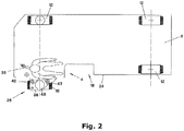
- the pivotable driving device 16 is derived from the in Fig. 2 shown pivoted position 26 beyond the zero side plane inwardly in a recess 18 of the machine frame 8, so that the outer edge of the pivotable driving device can be flush with the zero side 24.
- the pivoting device for the pivotable driving device 16 can have a link gear 30.
- the link mechanism can, for example, as shown, be designed with four joints 40, 41, 42, 43 having four vertical joint axes and with two links 44, 46 which can be pivoted in a horizontal plane.
- Two joints 40, 41 can be provided in a stationary manner on the machine frame 8 and two joints 42, 43 can be provided on the pivotable traveling device 16 in two vertically spaced-apart support plates 38, 39.
- the pivotable driving device can also be pivoted into more than one outer pivoted position.
- Fig. 3 shows a drive train of the construction machine 1.
- a first drive train I is used to transmit the drive power to the driving devices 12, 16.
- a second drive train II is provided to transmit the drive power to the milling drum 20.
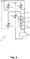
- the hydraulic drive train 70 is in the Fig. 4 explained in more detail.
- the drive train II for driving the milling drum 20 is shown in more detail.
- a drive motor, in particular an internal combustion engine 10 can be provided.
- the drive motor 10 can be provided via a flexible connection 22 with a pump distribution gear 17 for driving the first drive train I for driving a hydraulic drive system 70 for driving the driving device 12, 16.
- a clutch 15 can be provided between the drive motor 10 and the milling drum 20.
- the clutch 15 can be a device for switching the torque.
- a traction mechanism 13 for the mechanical drive of the milling drum 20 can be arranged between the clutch 15 and the milling drum 20.
- the traction mechanism 13 has a drive element 11 which is coupled non-rotatably to the drive shaft 23 of the drive motor 10.
- the traction mechanism 13 also has a drive element 21 which is coupled in a rotationally fixed manner to the drive shaft 19 of the milling drum 20.
- a transmission can also be arranged between the drive shaft 19 and the milling drum 20.
- the traction mechanism 13 is preferably a belt drive, whereby the drive and output elements can consist of pulleys 11, 21 over which one or more drive belts 31 run, whereby the drive and output elements can consist of pinions.
- the drive motor can also be hydraulic or electric.
- Fig. 4 the hydraulic drive system 70 is shown roughly schematically.
- This hydraulic drive system has at least one hydraulic pump 78, preferably a hydraulic variable displacement pump.
- the hydraulic drive system 70 has a hydraulic adjusting motor 72 for each driven travel device 12 in addition to the at least one pivotable travel device 16.
- the hydraulic adjusting motors are each preferably arranged on the respective driving devices 12.
- the hydraulic drive system can have a hydraulic reservoir 80.
- a hydraulic fixed-displacement motor 74 is provided to drive the at least one pivotable traveling device 16.
- a hydraulic fixed-displacement motor has a smaller installation space than a hydraulic variable-displacement motor.
- a controllable valve 76 in particular a throttle valve, is arranged in the supply lines 80, 82 assigned to the hydraulic constant motor 74.
- the hydraulic supply lines assigned to a hydraulic variable or constant motor are each the hydraulic lines in the hydraulic drive system 70, which run from the hydraulic pump to the respective variable or constant motor or also run from the respective variable or constant motor to a hydraulic reservoir.
- the supply lines associated with the constant motor in the illustrated embodiment are lines 82, 84.
- the supply line 82 leads from the hydraulic pump 78 to the hydraulic constant motor 74.
- the supply line 84 leads from the constant motor 74 to the hydraulic reservoir 80.
- the controllable valve is 75 arranged in the supply line 82 between the hydraulic pump 78 and the hydraulic fixed displacement motor 74.
- the hydraulic fixed-displacement motor 74 can be controlled in such a way that a behavior similar to that of a hydraulic variable-displacement motor can be achieved.
- the controllable valve 76 designed as a throttle valve is preferably a proportional valve. The pressure drop at the throttle valve and thus the hydraulic pressure at the hydraulic motor can be changed via the throttle valve, as a result of which the torque of the constant motor is adjusted. By reducing the drive torque, for example, the drive device can be prevented from spinning.
- volume flow control valve instead of a throttle valve to regulate the volume flow and thus to specify the speed of the hydraulic motor and thus also of the driving device.
- the driving devices 12, 16 can be provided with sensors for determining rotational speeds on the driving devices. These can be pick-up sensors, for example.
- the sensors can be used to determine whether there is slippage on the respective traveling device 12, 16, in particular by comparing the rotational speeds of the drives with one another. If there is slip, this can be reduced by activating the individual hydraulic adjusting motors and / or the throttle valve.
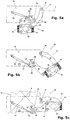
- the driving device 16 can be moved from a second pivoted-out position 26 into a first pivoted-in position 28 with the aid of a drive device 34. There can also be more than one swiveled-out position.
- the drive device 34 consists of a hydraulic piston-cylinder unit 33 with a push rod 35 and two link arms 36, 37.
- the link arm 37 is designed as a two-armed lever, one end being mounted on the machine frame 8 and the other end articulated to the second link arm 36 is.
- the other end of the second link arm 36 is connected to the link 44 of the pivot device.
- the push rod 35 can be actuated by the vehicle driver on the driver's cab 4.
- the driving device 16 In the retracted position of the push rod 35, the driving device 16 is in the second pivoted-out position, protruding over the zero side 24.
- the link mechanism 30 In the extended state of the push rod 35, the link mechanism 30 is pivoted so that the driving device 16 can be moved into the first pivoted-in position. Before the pivoting process, the driving device 16 can be raised with the aid of the lifting column 48 so that the driving device 16 can be pivoted without contacting the ground.
- the link mechanism 30 can be locked in the first pivoted-in position.
- other pivoting devices are also known in which the pivoting can take place, for example, while maintaining the ground contact of the driving device 16.
- the pivotable driving device 16 can be pivotable about vertical pivot axes 40, 41.
- the vertical pivot axis about which the pivotable driving device can be pivoted can also be displaceable.
Landscapes
- Engineering & Computer Science (AREA)
- Mechanical Engineering (AREA)
- Mining & Mineral Resources (AREA)
- Architecture (AREA)
- Civil Engineering (AREA)
- Structural Engineering (AREA)
- General Engineering & Computer Science (AREA)
- Fluid Mechanics (AREA)
- Physics & Mathematics (AREA)
- Chemical & Material Sciences (AREA)
- Combustion & Propulsion (AREA)
- Transportation (AREA)
- Operation Control Of Excavators (AREA)
Abstract
Description
- Die Erfindung betrifft eine selbstfahrende Baumaschine nach dem Oberbegriff des Anspruchs 1, sowie ein Verfahren zum Bearbeiten von Bodenbelägen nach dem Oberbegriff des Anspruchs 12.
- Es sind selbstfahrende Baumaschinen, insbesondere Straßenfräsmaschinen bekannt, die einen Maschinenrahmen und zumindest drei Fahreinrichtungen aufweisen, wobei zumindest eine der drei Fahreinrichtungen als schwenkbare Fahreinrichtung ausgeführt ist, so dass diese um eine vertikale Schwenkachse gegenüber dem Maschinenrahmen zwischen einer ersten eingeschwenkten und wenigstens einer zweiten ausgeschwenkten Position verschwenkbar ist. Ferner weist eine solche selbstfahrende Baumaschine zumindest eine Arbeitseinrichtung, insbesondere eine Fräswalze, zum Bearbeiten des Bodenbelags auf. Zum Antreiben der Fahreinrichtung ist häufig zumindest ein hydraulisches Antriebssystem vorgesehen.
- Die Arbeitseinrichtung kann auf einer Seite des Maschinenrahmens, nämlich der sogenannten Nullseite des Maschinenrahmens, bündig mit diesem abschließen, wobei die schwenkbare Fahreinrichtung vorzugsweise an dieser Nullseite des Maschinenrahmens angeordnet ist und wobei die schwenkbare Fahreinrichtung zwischen einer ersten eingeschwenkten, nicht gegenüber der Nullseite hervorstehenden Position und wenigstens einer zweiten ausgeschwenkten, gegenüber der Nullseite hervorstehenden Position verschwenkbar ist. Die schwenkbare Fahreinrichtung kann vorzugsweise eine hintere Fahreinrichtung sein.
- Soll die Arbeitseinrichtung beispielsweise kantennah an einer Hauswand oder einem ähnlichen Hindernis fräsen wird durch das Verschwenken der schwenkbaren Fahreinrichtung in die erste eingeschwenkte Position, vorzugsweise vor die Arbeitseirichtung, erreicht, dass die Baumaschine deutlich näher an das Hindernis heranfahren kann als es der Fall wäre, wenn die Fahreinrichtung neben Arbeitseinrichtung angeordnet wäre. Andererseits ist es beim nicht-kantennahen Fräsen wünschenswert, wenn die Fahreinrichtung neben der Arbeitseinrichtung angeordnet ist, um eine möglichst stabile Abstützung der Maschine zu erreichen.
- Problematisch bei den oben beschriebenen Baumaschinen, bei denen zumindest eine Fahreinrichtung schwenkbar ausgeführt ist, ist, dass Teile der Maschine, insbesondere Teile des hydraulischen Antriebssystems an der schwenkbaren Fahreinrichtung, ganz besonders der Hydraulikmotor dieses Fahrwerks, keinen zu großen Bauraum beanspruchen dürfen, insbesondere sich möglichst wenig über die seitliche Breite der Fahreinrichtungen hinaus erstrecken sollen, da sich die Teile sonst bei eingeschwenkter Fahreinrichtung über die übrigen Seitenteile der Baumaschine auf der Nullseite hinaus erstrecken und somit ein kantennahes Fräsen verhindern würden.
- Aus diesem Grund wurden im Stand der Technik bei Baumaschinen mit schwenkbaren Fahreinrichtungen bei einem hydraulischen Antriebssystem an allen angetriebenen Fahreinrichtungen hydraulische Konstantmotoren verwendet, da diese einen geringeren Bauraum aufweisen als hydraulische Verstellmotoren.
- Die bisher verwendeten hydraulischen Antriebssysteme weisen eine hydraulische Verstellpumpe und einen hydraulischen Mengenteiler auf, der gewährleistet, dass jeder Motor mit der gleichen Drehzahl angetrieben wird.
- Es besteht jedoch das Problem, dass bei einzelnen Fahreinrichtungen ein Schlupf auftreten kann, dem mit dem beschriebenen hydraulischen Antriebssystem nicht effektiv entgegengewirkt werden kann, insbesondere kann die Drehzahl der Fahreinrichtungen nur gemeinsam verstellt und nicht individuell angepasst werden, wie dies beispielsweise für die Einstellung eines Drehzahlunterschiedes zwischen kurveninneren und -äußeren Fahreinrichtungen wünschenswert wäre. Auch eine getrennte Verstellung des Antriebsmomentes der Fahreinrichtungen ist nicht möglich.
- Aufgabe der vorliegenden Erfindung ist es daher, bei einer selbstfahrenden Baumaschine mit verschwenkbarer Fahreinrichtung den Antrieb der Fahreinrichtungen zu verbessern.
- Gelöst wird diese Aufgabe durch die Merkmale der Ansprüche 1 und 12.
- Die Erfindung sieht in vorteilhafter Weise vor, dass das hydraulische Antriebssystem zum Antreiben der angetriebenen Fahreinrichtung außer der zumindest einen schwenkbaren Fahreinrichtung jeweils einen hydraulischen Verstellmotor aufweist, wobei das hydraulische Antriebssystem zum Antreiben der zumindest einen schwenkbaren Fahreinrichtung einen hydraulischen Konstantmotor aufweist.
- Der hydraulische Verstellmotor kann auch als regelbarer Hydraulikmotor bezeichnet werden. Ein hydraulischer Verstellmotor oder auch regelbarer Hydraulikmotor ist ein Hydraulikmotor oder Hydromotor, der durch eine Druckflüssigkeit angetrieben wird und bei gleichbleibendem Volumenstrom und gleichbleibendem Druck der Hydraulikflüssigkeit, insbesondere in der dem jeweiligen hydraulischen Verstellmotor zugeordneten hydraulischen Versorgungsleitung, in der Drehzahl verstellbar ist.
- Der hydraulische Konstantmotor kann auch als nicht-regelbarer Hydraulikmotor bezeichnet werden. Ein hydraulischer Konstantmotor oder auch nicht-regelbarer Hydraulikmotor ist ein Hydraulikmotor oder Hydromotor, der durch eine Druckflüssigkeit angetrieben wird und eine konstante Drehzahl aufweist bzw. bei gleichbleibendem Volumenstrom und gleichbleibendem Druck der Hydraulikflüssigkeit, insbesondere in der dem jeweiligen hydraulischen Konstantmotor zugeordneten hydraulischen Versorgungsleitung, in der Drehzahl nicht verstellbar ist.
- Das hydraulische Antriebssystem weist eine hydraulische Pumpe, insbesondere eine hydraulische Verstellpumpe auf. Ferner kann das hydraulische Antriebssystem auch eine Hydraulikreservoir aufweisen. Bei einem geschlossen Hyrdraulickreislauf wird die Hydraulikflüssigkeit kontinuierlich von der Pumpe über den Motor und wieder zurück gepumpt, bei einem offenen Hydraulikkreislauf fließt die Hydraulikflüssigkeit von dem Hydraulikmotor in ein Hydraulikreservoir aus dem die Pumpe die Hydraulikflüssigkeit wieder ansaugt.
- Die einem hydraulischen Verstell- oder Konstantmotor zugeordneten hydraulischen Versorgungsleitungen sind jeweils die hydraulischen Leitungen in dem hydraulischen Antriebssystem, die von der hydraulischen Pumpe zu dem jeweiligen Verstell- oder Konstantmotor laufen oder auch von dem jeweiligen Verstell- oder Konstantmotor weg zurück zur hydraulischen Pumpe oder zu einem Hydraulikreservoir laufen.
- Gemäß der vorliegenden Erfindung weisen alle angetriebenen Fahreinrichtungen außer der verschwenkbaren Fahreinrichtung einen hydraulischen Verstellmotor auf, mit denen an den jeweiligen Fahreinrichtungen eine genaue Einstellung der Drehzahl und damit z.B. eine Antriebs-Schupf-Regelung möglich ist. Um den Schlupf zu reduzieren, können die jeweiligen Fahreinrichtungen über die hydraulischen Verstellmotoren einzeln angesteuert werden.
- Die Steuerung kann in einem Ausführungsbeispiel darüber erfolgen, dass die hydraulischen Verstellmotoren und die Verstellpumpe koordiniert so verstellt werden, dass sich sowohl an den Verstellmotoren, als auch an dem Konstantmotor die erwünschte Drehzahl einstellt.
- Vorzugsweise weist das hydraulische Antriebssystem in den dem hydraulischem Konstantmotor zugeordneten Versorgungsleitungen ein regelbares Ventil auf.
- Hierbei ist das Ventil dazu vorgesehen den Druck und/oder den Volumenstrom in den Versorgungsleitungen des Konstantmotors anzupassen.
- Hierbei kann insbesondere über eine Anpassung des Drucks das Moment des Motors oder mit einer Änderung des Volumenstroms die Drehzahl des Motors angepasst werden.
- Grundsätzlich sind hierfür alle gängigen Ventile geeignet in einer besonders bevorzugten Ausführungsform wird ein Drosselventil verwendet. Das regelbare Ventil kann jedoch beispielsweise auch ein Volumenstromregelventil ist.
- Mit Hilfe des regelbaren Ventils kann auch der hydraulische Konstantmotor angesteuert werden. Der Volumenstrom oder der Druck kann mit Hilfe des Ventils verändert werden, wodurch die Drehzahl oder das Drehmoment des hydraulischen Konstantmotors verändert werden können. Auf diese Weise kann ein ähnliches Verhalten wie bei einem hydraulischen Verstellmotor an der schwenkbaren Fahreinrichtung erreicht werden. Es kann beispielsweise eine Antriebs-Schlupf-Regelung durchgeführt werden. Der Konstantmotor an sich ist jedoch nicht verstellbar.
- Das regelbare Ventil kann an der schwenkbaren Fahreinrichtung angeordnet sein.
- Alternativ kann das regelbare Ventil am Maschinenrahmen angeordnet sein.
- Es können vorzugsweise vier Fahreinrichtungen vorgesehen sein, die alle mittels des hydraulischen Antriebssystems antreibbar sind. Es kann vorzugsweise eine der vier Fahreinrichtungen die schwenkbare Fahreinrichtung sein.
- Die hydraulischen Verstellmotoren können jeweils an den jeweiligen angetriebenen Fahreinrichtungen angeordnet sein.
- Die hydraulischen Verstellmotoren können grundsätzlich in bekannter Weise ausgeführt und z. B. als Radialkolbenmotoren ausgebildet werden, besonders bevorzugt können hydraulisch verstellbare Axialkolbenmotoren vorgesehen sein.
- Als hydraulische Pumpe können die aus dem Stand der Technik bekannten Pumpen, wie z. B. Radialkolbenpumpen verwendet werden, besonders bevorzugt wird eine hydraulische Axialkolbenpumpe verwendet
- Die Fahreinrichtungen können lenkbar sein. Die Fahreinrichtungen können jeweils um eine Lenkachse lenkbar sein. Die Lenkachse verläuft vorzugsweise vertikal durch die Fahreinrichtung, wobei diese Achse insbesondere mittig durch die Fahreinrichtung verläuft.
- Auch die schwenkbare Fahreinrichtung kann um eine Lenkachse lenkbar sein, wobei die vertikale Schwenkachse gegenüber der Lenkachse versetzt ist. kann.
- Gemäß der vorliegenden Erfindung kann auch ein Verfahren zum Bearbeiten von Bodenbelägen mit einer mit Hilfe von zumindest drei Fahreinrichtungen selbstfahrenden Baumaschine, insbesondere Straßenfräsmaschine, vorgesehen sein, wobei bei der Baumaschine eine Arbeitseinrichtung, insbesondere eine Fräswalze, den Bodenbelag bearbeitet und bei der zumindest eine der drei Fahreinrichtungen als schwenkbare Fahreinrichtung ausgeführt ist, die um eine vertikale Schwenkachse gegenüber dem Maschinenrahmen zwischen einer ersten eingeschwenkten und wenigstens einer zweiten ausgeschwenkten Position verschwenkt werden kann, wobei zumindest zwei Fahreinrichtungen von einem hydraulischen Antriebssystem angetrieben werden, wobei das hydraulische Antriebssystem zumindest eine hydraulische Pumpe aufweist, und wobei zumindest eine der mindestens zwei angetriebenen Fahreinrichtungen die schwenkbare Fahreinrichtung ist.
- Erfindungsgemäß ist in vorteilhafter Weise vorgesehen, dass alle angetriebenen Fahreinrichtung außer der zumindest einen schwenkbaren Fahreinrichtung jeweils über einen hydraulischen Verstellmotor angetrieben werden, und die zumindest eine schwenkbare Fahreinrichtung über einen hydraulischen Konstantmotor angetrieben wird.
- Der hydraulische Konstantmotor kann über ein regelbares Ventil angesteuert werden.
- Wie bereits erläutert, hat dies den Vorteil, dass der hydraulische Konstantmotor über das Ventil derart angesteuert werden kann, dass ein ähnliches Verhalten wie bei einem Verstellmotor erreicht werden kann und so beispielsweise eine Antriebs-Schlupf-Regelung erfolgen kann.
- Das regelbare Ventil kann an dem Maschinenrahmen angeordnet sein.
- Alternativ kann das regelbare Ventil an der schwenkbaren Fahreinrichtung angeordnet werden.
- Im Folgenden werden unter Bezugnahme auf die Zeichnungen Ausführungsbeispiele der Erfindung näher erläutert.
- Es zeigen schematisch:
- Fig. 1
- eine erfindungsgemäße Baumaschine,
- Fig. 2
- eine Draufsicht auf die erfindungsgemäße Baumaschine,
- Fig. 3
- Antriebsstränge der Baumaschine,
- Fig. 4
- eine schematische Übersicht über das hydraulische Antriebssystem,
- Fig.5a-5c
- Bewegung der verschwenkbaren Fahreinrichtung.
-
Fig. 1 zeigt eine selbstfahrende Baumaschine 1. Im dargestellten Ausführungsbeispiel ist die selbstfahrende Baumaschine eine Straßenfräsmaschine. Die Baumaschine 1 weist einen Maschinenrahmen 8 auf und zumindest drei Fahreinrichtungen 12, 16. Die dargestellte Baumaschine 1 weist zwei vordere 12 und zwei hintere 12, 16 Fahreinrichtungen auf, von denen inFig.1 die jeweils in Arbeitsrichtung A links angeordneten Laufwerke nicht sichtbar sind. Die Fahreinrichtungen können, wie im dargestellten Ausführungsbeispiel, Räder oder alternativ auch Kettenlaufwerke sein. - Die Fahreinrichtungen 12, 16 können jeweils mittels zumindest eines hydraulischen Antriebssystems 70 angetrieben sein. Bei einer Baumaschine 1 können zumindest zwei Fahreinrichtungen angetrieben sein, wobei beispielsweise die vorderen Fahreinrichtungen 12 auch nicht angetrieben sein können. Zumindest eine der mindestens drei Fahreinrichtungen 12, 16 ist als schwenkbare Fahreinrichtung 16 ausgeführt. Diese kann um mindestens eine vertikale Schwenkachse gegenüber dem Maschinenrahmen 8 zwischen einer ersten eingeschwenkten und wenigstens einer zweiten ausgeschwenkten Position verschwenkbar sein. Dies wird anhand der
Fign. 2 und5 a-c näher erläutert. - Ferner ist zumindest eine Arbeitseinrichtung 20 vorgesehen, die wie im dargestellten Ausführungsbeispiel eine Fräswalze sein kann, um den Bodenbelag 3 zu bearbeiten. Auch die zumindest eine schwenkbare Fahreinrichtung 16 kann mittels des hydraulischen Antriebssystems 70 antreibbar sein. Wie
Fig. 2 zu entnehmen ist, weist die Baumaschine 1 eine sogenannte Nullseite 24 auf. Die Arbeitseinrichtung 20 ist mit ihrer einen Stirnseite nahezu bündig mit der Nullseite 24 des Maschinenrahmens 8 angeordnet, so dass auf der Nullseite der Baumaschine 1 ein kantennahes Arbeiten möglich ist. Hierzu wird die schwenkbare Fahreinrichtung 16 aus der inFig. 2 dargestellten ausgeschwenkten Position 26 jenseits der Nullseitenebene nach innen in einer Aussparung 18 des Maschinenrahmens 8 eingeschwenkt, so dass die Außenkante der schwenkbaren Fahreinrichtung bündig mit der Nullseite 24 abschließen kann. - Die Schwenkeinrichtung für die schwenkbare Fahreinrichtung 16 kann ein Lenkergetriebe 30 aufweisen. Das Lenkergetriebe kann beispielsweise, wie dargestellt, vier vertikale Gelenkachsen aufweisende Gelenke 40, 41, 42, 43 und mit zwei in einer horizontalen Ebene verschwenkbaren Lenkern 44, 46 ausgebildet sein. Zwei Gelenke 40, 41 können ortsfest an dem Maschinenrahmen 8 und zwei Gelenke 42, 43 können an der schwenkbaren Fahreinrichtung 16 jeweils in zwei vertikale beabstandeten Tragplatten 38, 39 vorgesehen sein.
- Die schwenkbare Fahreinrichtung kann auch in mehr als eine äußere ausgeschwenkte Position verschwenkbar sein.
-
Fig. 3 zeigt einen Antriebsstrang der Baumaschine 1. Zur Übertragung der Antriebsleistung auf die Fahreinrichtungen 12, 16 dient ein erster Antriebsstrang I. Dieser umfasst ein hydraulisches Antriebssystem 70. Zur Übertragung der Antriebsleistung auf die Fräswalze 20 ist ein zweiter Antriebsstrang II vorgesehen. Der hydraulische Antriebsstrang 70 wird in derFig. 4 näher erläutert. In derFig. 3 ist der Antriebsstrang II zum Antrieb der Fräswalze 20 näher dargestellt. Es kann ein Antriebsmotor, insbesondere ein Verbrennungsmotor 10 vorgesehen sein. Der Antriebsmotor 10 kann über eine flexible Verbindung 22 mit einem Pumpenverteilgetriebe 17 zum Antreiben des ersten Antriebsstrangs I zum Antreiben eines hydraulischen Antriebssystems 70 zum Antreiben der Fahreinrichtung 12, 16 vorgesehen sein. - Im zweiten Antriebsstrang II zum Antreiben der Fräswalze 20 kann zwischen dem Antriebsmotor 10 und der Fräswalze 20 eine Schaltkupplung 15 vorgesehen sein. Die Schaltkupplung 15 kann eine Einrichtung zum Schalten des Drehmoments sein.
- Zwischen der Schaltkupplung 15 und der Fräswalze 20 kann ein Zugmittelgetriebe 13 für den mechanischen Antrieb der Fräswalze 20 angeordnet sein. Das Zugmittelgetriebe 13 weist ein Antriebselement 11 auf, das mit der Antriebswelle 23 des Antriebsmotors 10 drehfest gekoppelt ist. Ferner weist das Zugmittelgetriebe 13 ein Antriebselement 21 auf, das mit der Antriebswelle 19 der Fräswalze 20 drehfest gekoppelt ist. Zwischen Antriebswelle 19 und der Fräswalze 20 kann auch ein Getriebe angeordnet sein.
- Das Zugmittelgetriebe 13 ist vorzugsweise ein Riemenantrieb, wobei die Antriebs- und Abtriebselemente aus Riemenscheiben 11, 21 bestehen können, über die ein oder mehrere Antriebsriemen 31 laufen, wobei die Antriebs- und Abtriebselemente aus Ritzeln bestehen können. Grundsätzlich kann der Antriebsmotor auch hydraulisch oder elektrisch sein.
- In
Fig. 4 ist das hydraulische Antriebssystem 70 grobschematisch dargestellt. Dieses hydraulische Antriebssystem weist zumindest eine hydraulische Pumpe 78, vorzugsweise eine hydraulische Verstellpumpe auf. - Das hydraulische Antriebssystem 70 weist für jede angetriebene Fahreinrichtung 12 außer der zumindest einen schwenkbaren Fahreinrichtung 16 jeweils einen hydraulischen Verstellmotor 72 auf. Die hydraulischen Verstellmotoren sind jeweils vorzugsweise an den jeweiligen Fahreinrichtungen 12 angeordnet. Ferner kann das hydraulische Antriebssystem ein Hydraulikreservoir 80 aufweisen.
- Zum Antreiben der zumindest einen schwenkbaren Fahreinrichtung 16 ist ein hydraulischer Konstantmotor 74 vorgesehen.
- Ein hydraulischer Konstantmotor weist einen geringeren Bauraum auf als ein hydraulischer Verstellmotor.
- In den dem hydraulischen Konstantmotor 74 zugeordneten Versorgungsleitungen 80, 82 ist im dargestellten Ausführungsbeispiel ein regelbares Ventil 76, insbesondere ein Drosselventil, angeordnet. Die einem hydraulischen Verstell- oder Konstantmotor zugeordneten hydraulischen Versorgungsleitungen sind jeweils die hydraulischen Leitungen in dem hydraulischen Antriebssystem 70, die von der hydraulischen Pumpe zu dem jeweiligen Verstell- oder Konstantmotor laufen oder auch von dem jeweiligen Verstell- oder Konstantmotor weg zu einem Hydraulikreservoir laufen. Die dem Konstantmotor im dargestellten Ausführungsbeispiel zugeordneten Versorgungsleitungen sind die Leitungen 82, 84. Die Versorgungsleitung 82 führt von der hydraulischen Pumpe 78 zu dem hydraulischen Konstantmotor 74. Die Versorgungsleitung 84 führt von dem Konstantmotor 74 zu dem Hydraulikreservoir 80. Im dargestellten Ausführungsbeispiel ist das regelbare Ventil 75 in der Versorgungsleitung 82 wischen der hydraulischen Pumpe 78 und dem hydraulischen Konstantmotor 74 angeordnet.
- Mittels des regelbaren Ventils 76 kann der hydraulische Konstantmotor 74 derart angesteuert werden, dass ein ähnliches Verhalten erreicht werden kann, wie bei einem hydraulischen Verstellmotor. Das als Drosselventil ausgeführte regelbare Ventil 76 ist vorzugsweise ein Proportionalventil. Über das Drosselventil kann der Druckabfall an dem Drosselventil und damit der Hydraulikdruck am Hydraulikmotor geändert werden, wodurch das Moment des Konstantmotors angepasst wird. Durch eine Reduzierung des Antriebsmomentes kann beispielsweise ein Durchdrehen der Fahreinrichtung verhindert werden.
- Grundsätzlich ist es auch möglich mit einem Volumenstromregelventil anstelle eines Drosselventils den Volumenstrom zu Regeln und damit die Drehzahl des Hydraulikmotors und somit auch der Fahreinrichtung vorzugeben.
- Die Fahreinrichtungen 12, 16 können Sensoren zur Ermittlung Drehgeschwindigkeiten an den Fahreinrichtungen vorgesehen sein. Dies können beispielsweise Pickup-Sensoren sein. Mittels der Sensoren kann festgestellt werden, ob ein Schlupf an der jeweiligen Fahreinrichtung 12, 16 vorliegt, insbesondere indem die Drehzahlen der Laufwerke miteinander verglichen werden. Falls ein Schlupf vorliegt, so kann dieser durch Ansteuern der einzelnen hydraulischen Verstellmotoren und/oder des Drosselventils reduziert werden.
- In den
Fig. 5a bis 5c ist noch einmal näher dargestellt, wie die schwenkbare Fahreinrichtung 16 verschwenkt werden kann. Die Fahreinrichtung 16 kann von einer zweiten ausgeschwenkten Position 26 in eine erste eingeschwenkte Position 28 mit Hilfe einer Antriebseinrichtung 34 bewegt werden. Es kann auch mehr als eine ausgeschwenkte Position existieren. - Die Antriebseinrichtung 34 besteht aus einer hydraulischen KolbenZylindereinheit 33 mit einer Schubstange 35 und zwei Lenkerarmen 36, 37. Der Lenkerarm 37 ist als zweiarmiger Hebel gestaltet, wobei das eine Ende an dem Maschinenrahmen 8 gelagert ist und das andere Ende mit dem zweiten Lenkerarm 36 gelenkig verbunden ist. Das andere Ende des zweiten Lenkerarms 36 ist mit dem Lenker 44 der Schwenkeinrichtung verbunden.
- Die Schubstange 35 kann von dem Fahrzeugführer auf dem Fahrerstand 4 betätigt werden. In der eingezogenen Position der Schubstange 35 befindet sich die Fahreinrichtung 16 in der zweiten ausgeschwenkten Position, über der Nullseite 24 überstehend. Im ausgefahrenen Zustand der Schubstange 35 wird das Lenkergetriebe 30 verschwenkt, so dass die Fahreinrichtung 16 in die erste eingeschwenkte Position bewegt werden kann. Vor dem Schwenkvorgang kann die Fahreinrichtung 16 mit Hilfe der Hubsäule 48 angehoben werden, damit die Fahreinrichtung 16 ohne Bodenkontakt verschwenkt werden kann. In der ersten eingeschwenkten Position kann eine Arretierung des Lenkergetriebes 30 erfolgen. Prinzipiell sind auch andere Schwenkvorrichtungen bekannt bei denen das Verschwenken beispielsweise unter Beibehaltung des Bodenkontakts der Fahreinrichtung 16 erfolgen kann.
- Die schwenkbare Fahreinrichtung 16 kann um vertikale Schwenkachsen 40, 41 verschwenkbar sein. Die vertikale Schwenkachse, um die die schwenkbare Fahreinrichtung verschwenkt werden kann, kann auch verschiebbar sein.
Claims (15)
- Selbstfahrende Baumaschine (1), insbesondere Straßenfräsmaschine, mit- einem Maschinenrahmen (8),- zumindest drei Fahreinrichtungen (12, 16),- wobei zumindest eine der drei Fahreinrichtungen (12, 16) als schwenkbare Fahreinrichtung (16) aufgeführt ist, so dass diese um mindestens eine vertikale Schwenkachse gegenüber dem Maschinenrahmen (8) zwischen einer ersten eingeschwenkten und wenigstens einer zweiten ausgeschwenkten Position verschwenkbar ist,- zumindest einer Arbeitseinrichtung (20), insbesondere einer Fräswalze, zum Bearbeiten des Bodenbelags (3),- zumindest einem hydraulischen Antriebssystem (70) zum Antreiben mindestens zweier Fahreinrichtungen (12, 16), wobei zumindest eine der mindestens zwei angetriebenen Fahreinrichtungen die schwenkbare Fahreinrichtung (16) ist, wobei das hydraulische Antriebssystem (70) zumindest eine hydraulische Pumpe (78) aufweist,dadurch gekennzeichnet,
dass das hydraulische Antriebssystem (70) zum Antreiben der angetriebenen Fahreinrichtung (12) außer der zumindest einen schwenkbaren Fahreinrichtung (16) jeweils einen hydraulischen Verstellmotor (72) aufweist, wobei das hydraulische Antriebssystem (70) zum Antreiben der zumindest einen schwenkbaren Fahreinrichtung (16) ein hydraulischen Konstantmotor (74) aufweist. - Baumaschine (1) nach Anspruch 1, dadurch gekennzeichnet, dass das hydraulische Antriebssystem (70) in den dem hydraulischem Konstantmotor (74) zugeordneten Versorgungsleitungen (80, 82, 84) ein regelbares Ventil (76) aufweist.
- Baumaschine (1) nach Anspruch 2, dadurch gekennzeichnet, dass das regelbare Ventil (76) am Maschinenrahmen (8) angeordnet ist.
- Baumaschine (1) nach Anspruch 2, dadurch gekennzeichnet, dass das regelbare Ventil (76) an der schwenkbaren Fahreinrichtung (16) angeordnet ist.
- Baumaschine (1) nach einem der Ansprüche 2 bis 4, dadurch gekennzeichnet, dass das regelbare Ventil ein Drosselventil oder ein Volumenstromregelventil ist.
- Baumaschine (1) nach einem der Ansprüche 1 bis 5, dadurch gekennzeichnet, dass vier Fahreinrichtungen (12, 16) vorgesehen sind, die alle mittels des hydraulischen Antriebssystems (70) antreibbar sind, wobei eine der vier Fahreinrichtungen (12, 16) die schwenkbare Fahreinrichtung (16) ist.
- Baumaschine (1) nach einem der Ansprüche 1 bis 6, dadurch gekennzeichnet, dass die hydraulischen Verstellmotoren (72) an den jeweiligen angetriebenen Fahreinrichtungen (12) angeordnet sind.
- Baumaschine (1) nach einem der Ansprüche 1 bis 7, dadurch gekennzeichnet, dass die hydraulischen Verstellmotoren (72) hydraulisch verstellbare Axialkolbenmotoren sind.
- Baumaschine (1) nach einem der Ansprüche 1 bis 8, dadurch gekennzeichnet, dass die hydraulische Pumpe (78) eine hydraulische Axialkolbenpumpe ist.
- Baumaschine (1) nach einem der Ansprüche 1 bis 9, dadurch gekennzeichnet, dass der hydraulische Konstantmotor (74) ein nicht verstellbarer Axialkolbenmotor ist.
- Baumaschine (1) nach einem der Ansprüche 1 bis 10, dadurch gekennzeichnet, dass die schwenkbare Fahreinrichtung (16) um eine Lenkachse lenkbar ist und die vertikale Schwenkachse gegenüber der Lenkachse versetzt ist.
- Baumaschine (1) nach einem der Ansprüche 1 bis 11, dadurch gekennzeichnet, dass die Arbeitseinrichtung (20) auf einer Seite des Maschinenrahmens (8), nämlich der sogenannten Nullseite (24) des Maschinenrahmens (8), bündig mit diesem abschließt, wobei die schwenkbare Fahreinrichtung (16) an dieser Nullseite (24) des Maschinenrahmens (8) angeordnet ist, wobei die schwenkbare Fahreinrichtung (16) zwischen der ersten eingeschwenkten, nicht gegenüber der Nullseite (24) hervorstehenden Position und wenigstens einer zweiten ausgeschwenkten, gegenüber der Nullseite (24) hervorstehenden Position verschwenkbar ist.
- Verfahren zum Bearbeiten von Bodenbelägen mit einer mit Hilfe von zumindest drei Fahreinrichtungen (12,16) selbstfahrenden Baumaschine (1), insbesondere Straßenfräsmaschine, bei der eine Arbeitseinrichtung (20), insbesondere eine Fräswalze, den Bodenbelag (3) bearbeitet und bei der zumindest eine der drei Fahreinrichtungen (12, 16) als schwenkbare Fahreinrichtung (16) aufgeführt ist, die um eine vertikale Schwenkachse gegenüber dem Maschinenrahmen (8) zwischen einer ersten eingeschwenkten und wenigstens einer zweiten ausgeschwenkten Position verschwenkt werden kann, wobei zumindest zwei Fahreinrichtungen (12, 16) von einem hydraulischen Antriebssystem (70) angetrieben werden, wobei das hydraulische Antriebssystem (70) zumindest eine hydraulische Pumpe (78) aufweist und wobei zumindest eine der mindestens zwei angetriebenen Fahreinrichtungen die schwenkbare Fahreinrichtung (16) ist,
dadurch gekennzeichnet,
dass alle angetriebenen Fahreinrichtung (12) außer der zumindest einen schwenkbaren Fahreinrichtung (16) jeweils über einen hydraulischen Verstellmotor (72) angetrieben werden und die zumindest eine schwenkbare Fahreinrichtung (16) über einen hydraulischen Konstantmotor (74) angetrieben wird. - Verfahren nach Anspruch 13, dadurch gekennzeichnet, dass der hydraulische Konstantmotor (74) über ein regelbares Ventil (76) angesteuert wird.
- Verfahren nach Anspruch 14, dadurch gekennzeichnet, dass das regelbare Ventil (76) am Maschinenrahmen (8) angeordnet wird.
Applications Claiming Priority (1)
| Application Number | Priority Date | Filing Date | Title |
|---|---|---|---|
| DE102019220552.6A DE102019220552A1 (de) | 2019-12-23 | 2019-12-23 | Selbstfahrende Baumaschine |
Publications (2)
| Publication Number | Publication Date |
|---|---|
| EP3842592A1 true EP3842592A1 (de) | 2021-06-30 |
| EP3842592B1 EP3842592B1 (de) | 2023-07-05 |
Family
ID=73789951
Family Applications (1)
| Application Number | Title | Priority Date | Filing Date |
|---|---|---|---|
| EP20212789.0A Active EP3842592B1 (de) | 2019-12-23 | 2020-12-09 | Selbstfahrende baumaschine |
Country Status (4)
| Country | Link |
|---|---|
| US (1) | US11193247B2 (de) |
| EP (1) | EP3842592B1 (de) |
| CN (1) | CN113089440B (de) |
| DE (1) | DE102019220552A1 (de) |
Families Citing this family (1)
| Publication number | Priority date | Publication date | Assignee | Title |
|---|---|---|---|---|
| DE102019135668A1 (de) * | 2019-12-23 | 2021-06-24 | Wirtgen Gmbh | Selbstfahrende Baumaschine und Verfahren zum Steuern einer selbstfahrenden Baumaschine |
Citations (2)
| Publication number | Priority date | Publication date | Assignee | Title |
|---|---|---|---|---|
| EP0916004A1 (de) * | 1996-08-01 | 1999-05-19 | WIRTGEN GmbH | Strassenbaumaschinen zum bearbeiten von fahrbahnen |
| US20130000996A1 (en) * | 2011-06-30 | 2013-01-03 | Caterpillar Inc. | Mobile machine with a support system |
Family Cites Families (7)
| Publication number | Priority date | Publication date | Assignee | Title |
|---|---|---|---|---|
| US4325580A (en) * | 1979-05-07 | 1982-04-20 | Cmi Corporation | Roadway planing apparatus |
| DE19750367C2 (de) * | 1997-11-14 | 2001-07-05 | Danfoss Fluid Power As Nordbor | Hydraulischer Fahrzeugantrieb und Ventilmodul hierfür |
| DE102004040135B3 (de) * | 2004-08-19 | 2005-12-15 | Abg Allgemeine Baumaschinen-Gesellschaft Mbh | Selbstfahrendes Gerät zum Abfräsen von Verkehrsflächen |
| WO2008042244A2 (en) * | 2006-09-29 | 2008-04-10 | Volvo Construction Equipment Ab | Propulsion and steering system for a road milling machine |
| CN103569106B (zh) * | 2013-11-08 | 2016-03-23 | 中联重科股份有限公司 | 履带防打滑控制方法、装置和铣刨机 |
| DK3009675T3 (da) * | 2014-10-13 | 2019-11-11 | Danfoss Power Solutions Gmbh & Co Ohg | Styring til hydraulisk pumpe |
| US9684308B2 (en) * | 2014-11-13 | 2017-06-20 | Wirtgen Gmbh | Transport mode conversion |
-
2019
- 2019-12-23 DE DE102019220552.6A patent/DE102019220552A1/de active Pending
-
2020
- 2020-12-09 EP EP20212789.0A patent/EP3842592B1/de active Active
- 2020-12-09 CN CN202011447580.0A patent/CN113089440B/zh active Active
- 2020-12-11 US US17/119,021 patent/US11193247B2/en active Active
Patent Citations (2)
| Publication number | Priority date | Publication date | Assignee | Title |
|---|---|---|---|---|
| EP0916004A1 (de) * | 1996-08-01 | 1999-05-19 | WIRTGEN GmbH | Strassenbaumaschinen zum bearbeiten von fahrbahnen |
| US20130000996A1 (en) * | 2011-06-30 | 2013-01-03 | Caterpillar Inc. | Mobile machine with a support system |
Also Published As
| Publication number | Publication date |
|---|---|
| DE102019220552A1 (de) | 2021-06-24 |
| CN113089440B (zh) | 2023-09-26 |
| CN113089440A (zh) | 2021-07-09 |
| US11193247B2 (en) | 2021-12-07 |
| EP3842592B1 (de) | 2023-07-05 |
| US20210189668A1 (en) | 2021-06-24 |
Similar Documents
| Publication | Publication Date | Title |
|---|---|---|
| EP0756656B1 (de) | Maschine zum bearbeiten von fahrbahnen | |
| DE10357074B3 (de) | Selbstfahrende Maschine zum Herstellen von Fahrbahnen | |
| DE10120732A1 (de) | Anbauschnittstelle zwischen Arbeitsfahrzeug und Arbeitsgeräten sowie Steuereinrichtung | |
| DE2630457B2 (de) | Bodenplaniermaschine | |
| DE102016216584A1 (de) | System und verfahren zum reagieren auf radschlupf in einem zugfahrzeug | |
| DE112010004297T5 (de) | Motor-Grader mit variablem Radstand | |
| DE2342450A1 (de) | Anordnung zum steuern von hydrostatischen getrieben | |
| EP2930086A2 (de) | Selbstfahrende erntemaschine | |
| DE69617787T2 (de) | Lenkung für ein Knickrahmenfahrzeug | |
| DE2652823A1 (de) | Bremsgelenktes fahrzeug, insbesondere zugmaschine, mit lenkhebel und einer hilfssteuerung mit selbstzentriervorrichtung | |
| EP3889355B1 (de) | Selbstfahrende baumaschine und verfahren zum bearbeiten von bodenbelägen | |
| EP4159589A1 (de) | Bodenbearbeitungsmaschine und verfahren zum betreiben einer bodenbearbeitungsmaschine | |
| DE102013009816A1 (de) | Bodenfräsmaschine, insbesondere Straßenkaltfräse | |
| DE2262922C2 (de) | Schlepper mit einer Dreipunkthebevorrichtung für ein Bodenbearbeitungsgerät | |
| EP3842592B1 (de) | Selbstfahrende baumaschine | |
| DE19616405B4 (de) | Vorrichtung zur Verhinderung des Aufstellens einer Tandemachse | |
| EP1645690B1 (de) | Vorrichtung zum Sanieren und Herstellen von tragfähigen Oberflächen | |
| EP0681063A2 (de) | Fräsmaschine | |
| EP3842667B1 (de) | Selbstfahrende baumaschine und verfahren zum steuern einer selbstfahrenden baumaschine | |
| DE2053698A1 (de) | Steuereinrichtung für eine hydrostatisch angetriebene Überlagerungslenkung von Kettenfahrzeugen | |
| EP4368481B1 (de) | Bodenfräsmaschine, verfahren zum fahren einer bodenfräsmaschine und verfahren zum positionieren einer bodenfräsmaschine | |
| DE102005037389B4 (de) | Vielzweckarbeitsgerät | |
| DE102023135043A1 (de) | Verfahren zur Lenksteuerung einer knickgelenkten Baumaschine, insbesondere einer selbstfahrenden Bodenverdichtungsmaschine, insbesondere eines Walzenzug oder einer Tandemwalze, mithilfe einer Lenksteuereinheit sowie knickgelenkte Baumaschine, insbesondere selbstfahrende Bodenverdichtungsmaschine | |
| DE3921869C1 (en) | Compact loader for road surfacing machine - has powered cold grinder, hydraulic pumps and manual control lever | |
| DE4142043C2 (de) |
Legal Events
| Date | Code | Title | Description |
|---|---|---|---|
| PUAI | Public reference made under article 153(3) epc to a published international application that has entered the european phase |
Free format text: ORIGINAL CODE: 0009012 |
|
| STAA | Information on the status of an ep patent application or granted ep patent |
Free format text: STATUS: THE APPLICATION HAS BEEN PUBLISHED |
|
| AK | Designated contracting states |
Kind code of ref document: A1 Designated state(s): AL AT BE BG CH CY CZ DE DK EE ES FI FR GB GR HR HU IE IS IT LI LT LU LV MC MK MT NL NO PL PT RO RS SE SI SK SM TR |
|
| STAA | Information on the status of an ep patent application or granted ep patent |
Free format text: STATUS: REQUEST FOR EXAMINATION WAS MADE |
|
| 17P | Request for examination filed |
Effective date: 20211229 |
|
| RBV | Designated contracting states (corrected) |
Designated state(s): AL AT BE BG CH CY CZ DE DK EE ES FI FR GB GR HR HU IE IS IT LI LT LU LV MC MK MT NL NO PL PT RO RS SE SI SK SM TR |
|
| GRAP | Despatch of communication of intention to grant a patent |
Free format text: ORIGINAL CODE: EPIDOSNIGR1 |
|
| STAA | Information on the status of an ep patent application or granted ep patent |
Free format text: STATUS: GRANT OF PATENT IS INTENDED |
|
| GRAJ | Information related to disapproval of communication of intention to grant by the applicant or resumption of examination proceedings by the epo deleted |
Free format text: ORIGINAL CODE: EPIDOSDIGR1 |
|
| STAA | Information on the status of an ep patent application or granted ep patent |
Free format text: STATUS: REQUEST FOR EXAMINATION WAS MADE |
|
| INTG | Intention to grant announced |
Effective date: 20220407 |
|
| GRAP | Despatch of communication of intention to grant a patent |
Free format text: ORIGINAL CODE: EPIDOSNIGR1 |
|
| STAA | Information on the status of an ep patent application or granted ep patent |
Free format text: STATUS: GRANT OF PATENT IS INTENDED |
|
| INTC | Intention to grant announced (deleted) | ||
| INTG | Intention to grant announced |
Effective date: 20220517 |
|
| GRAJ | Information related to disapproval of communication of intention to grant by the applicant or resumption of examination proceedings by the epo deleted |
Free format text: ORIGINAL CODE: EPIDOSDIGR1 |
|
| STAA | Information on the status of an ep patent application or granted ep patent |
Free format text: STATUS: REQUEST FOR EXAMINATION WAS MADE |
|
| GRAP | Despatch of communication of intention to grant a patent |
Free format text: ORIGINAL CODE: EPIDOSNIGR1 |
|
| STAA | Information on the status of an ep patent application or granted ep patent |
Free format text: STATUS: GRANT OF PATENT IS INTENDED |
|
| INTC | Intention to grant announced (deleted) | ||
| INTG | Intention to grant announced |
Effective date: 20221020 |
|
| GRAJ | Information related to disapproval of communication of intention to grant by the applicant or resumption of examination proceedings by the epo deleted |
Free format text: ORIGINAL CODE: EPIDOSDIGR1 |
|
| STAA | Information on the status of an ep patent application or granted ep patent |
Free format text: STATUS: REQUEST FOR EXAMINATION WAS MADE |
|
| INTC | Intention to grant announced (deleted) | ||
| GRAP | Despatch of communication of intention to grant a patent |
Free format text: ORIGINAL CODE: EPIDOSNIGR1 |
|
| STAA | Information on the status of an ep patent application or granted ep patent |
Free format text: STATUS: GRANT OF PATENT IS INTENDED |
|
| INTG | Intention to grant announced |
Effective date: 20230109 |
|
| GRAS | Grant fee paid |
Free format text: ORIGINAL CODE: EPIDOSNIGR3 |
|
| GRAA | (expected) grant |
Free format text: ORIGINAL CODE: 0009210 |
|
| STAA | Information on the status of an ep patent application or granted ep patent |
Free format text: STATUS: THE PATENT HAS BEEN GRANTED |
|
| AK | Designated contracting states |
Kind code of ref document: B1 Designated state(s): AL AT BE BG CH CY CZ DE DK EE ES FI FR GB GR HR HU IE IS IT LI LT LU LV MC MK MT NL NO PL PT RO RS SE SI SK SM TR |
|
| P01 | Opt-out of the competence of the unified patent court (upc) registered |
Effective date: 20230527 |
|
| REG | Reference to a national code |
Ref country code: CH Ref legal event code: EP |
|
| REG | Reference to a national code |
Ref country code: AT Ref legal event code: REF Ref document number: 1584942 Country of ref document: AT Kind code of ref document: T Effective date: 20230715 |
|
| REG | Reference to a national code |
Ref country code: DE Ref legal event code: R096 Ref document number: 502020004026 Country of ref document: DE |
|
| REG | Reference to a national code |
Ref country code: IE Ref legal event code: FG4D Free format text: LANGUAGE OF EP DOCUMENT: GERMAN |
|
| REG | Reference to a national code |
Ref country code: SE Ref legal event code: TRGR |
|
| REG | Reference to a national code |
Ref country code: LT Ref legal event code: MG9D |
|
| REG | Reference to a national code |
Ref country code: NL Ref legal event code: MP Effective date: 20230705 |
|
| PG25 | Lapsed in a contracting state [announced via postgrant information from national office to epo] |
Ref country code: NL Free format text: LAPSE BECAUSE OF FAILURE TO SUBMIT A TRANSLATION OF THE DESCRIPTION OR TO PAY THE FEE WITHIN THE PRESCRIBED TIME-LIMIT Effective date: 20230705 |
|
| PG25 | Lapsed in a contracting state [announced via postgrant information from national office to epo] |
Ref country code: GR Free format text: LAPSE BECAUSE OF FAILURE TO SUBMIT A TRANSLATION OF THE DESCRIPTION OR TO PAY THE FEE WITHIN THE PRESCRIBED TIME-LIMIT Effective date: 20231006 |
|
| PG25 | Lapsed in a contracting state [announced via postgrant information from national office to epo] |
Ref country code: ES Free format text: LAPSE BECAUSE OF FAILURE TO SUBMIT A TRANSLATION OF THE DESCRIPTION OR TO PAY THE FEE WITHIN THE PRESCRIBED TIME-LIMIT Effective date: 20230705 |
|
| PG25 | Lapsed in a contracting state [announced via postgrant information from national office to epo] |
Ref country code: IS Free format text: LAPSE BECAUSE OF FAILURE TO SUBMIT A TRANSLATION OF THE DESCRIPTION OR TO PAY THE FEE WITHIN THE PRESCRIBED TIME-LIMIT Effective date: 20231105 |
|
| PG25 | Lapsed in a contracting state [announced via postgrant information from national office to epo] |
Ref country code: RS Free format text: LAPSE BECAUSE OF FAILURE TO SUBMIT A TRANSLATION OF THE DESCRIPTION OR TO PAY THE FEE WITHIN THE PRESCRIBED TIME-LIMIT Effective date: 20230705 Ref country code: PT Free format text: LAPSE BECAUSE OF FAILURE TO SUBMIT A TRANSLATION OF THE DESCRIPTION OR TO PAY THE FEE WITHIN THE PRESCRIBED TIME-LIMIT Effective date: 20231106 Ref country code: NO Free format text: LAPSE BECAUSE OF FAILURE TO SUBMIT A TRANSLATION OF THE DESCRIPTION OR TO PAY THE FEE WITHIN THE PRESCRIBED TIME-LIMIT Effective date: 20231005 Ref country code: LV Free format text: LAPSE BECAUSE OF FAILURE TO SUBMIT A TRANSLATION OF THE DESCRIPTION OR TO PAY THE FEE WITHIN THE PRESCRIBED TIME-LIMIT Effective date: 20230705 Ref country code: LT Free format text: LAPSE BECAUSE OF FAILURE TO SUBMIT A TRANSLATION OF THE DESCRIPTION OR TO PAY THE FEE WITHIN THE PRESCRIBED TIME-LIMIT Effective date: 20230705 Ref country code: IS Free format text: LAPSE BECAUSE OF FAILURE TO SUBMIT A TRANSLATION OF THE DESCRIPTION OR TO PAY THE FEE WITHIN THE PRESCRIBED TIME-LIMIT Effective date: 20231105 Ref country code: HR Free format text: LAPSE BECAUSE OF FAILURE TO SUBMIT A TRANSLATION OF THE DESCRIPTION OR TO PAY THE FEE WITHIN THE PRESCRIBED TIME-LIMIT Effective date: 20230705 Ref country code: GR Free format text: LAPSE BECAUSE OF FAILURE TO SUBMIT A TRANSLATION OF THE DESCRIPTION OR TO PAY THE FEE WITHIN THE PRESCRIBED TIME-LIMIT Effective date: 20231006 Ref country code: FI Free format text: LAPSE BECAUSE OF FAILURE TO SUBMIT A TRANSLATION OF THE DESCRIPTION OR TO PAY THE FEE WITHIN THE PRESCRIBED TIME-LIMIT Effective date: 20230705 Ref country code: ES Free format text: LAPSE BECAUSE OF FAILURE TO SUBMIT A TRANSLATION OF THE DESCRIPTION OR TO PAY THE FEE WITHIN THE PRESCRIBED TIME-LIMIT Effective date: 20230705 |
|
| PG25 | Lapsed in a contracting state [announced via postgrant information from national office to epo] |
Ref country code: PL Free format text: LAPSE BECAUSE OF FAILURE TO SUBMIT A TRANSLATION OF THE DESCRIPTION OR TO PAY THE FEE WITHIN THE PRESCRIBED TIME-LIMIT Effective date: 20230705 |
|
| REG | Reference to a national code |
Ref country code: DE Ref legal event code: R097 Ref document number: 502020004026 Country of ref document: DE |
|
| PG25 | Lapsed in a contracting state [announced via postgrant information from national office to epo] |
Ref country code: SM Free format text: LAPSE BECAUSE OF FAILURE TO SUBMIT A TRANSLATION OF THE DESCRIPTION OR TO PAY THE FEE WITHIN THE PRESCRIBED TIME-LIMIT Effective date: 20230705 Ref country code: RO Free format text: LAPSE BECAUSE OF FAILURE TO SUBMIT A TRANSLATION OF THE DESCRIPTION OR TO PAY THE FEE WITHIN THE PRESCRIBED TIME-LIMIT Effective date: 20230705 Ref country code: EE Free format text: LAPSE BECAUSE OF FAILURE TO SUBMIT A TRANSLATION OF THE DESCRIPTION OR TO PAY THE FEE WITHIN THE PRESCRIBED TIME-LIMIT Effective date: 20230705 Ref country code: DK Free format text: LAPSE BECAUSE OF FAILURE TO SUBMIT A TRANSLATION OF THE DESCRIPTION OR TO PAY THE FEE WITHIN THE PRESCRIBED TIME-LIMIT Effective date: 20230705 Ref country code: CZ Free format text: LAPSE BECAUSE OF FAILURE TO SUBMIT A TRANSLATION OF THE DESCRIPTION OR TO PAY THE FEE WITHIN THE PRESCRIBED TIME-LIMIT Effective date: 20230705 Ref country code: SK Free format text: LAPSE BECAUSE OF FAILURE TO SUBMIT A TRANSLATION OF THE DESCRIPTION OR TO PAY THE FEE WITHIN THE PRESCRIBED TIME-LIMIT Effective date: 20230705 |
|
| PLBE | No opposition filed within time limit |
Free format text: ORIGINAL CODE: 0009261 |
|
| STAA | Information on the status of an ep patent application or granted ep patent |
Free format text: STATUS: NO OPPOSITION FILED WITHIN TIME LIMIT |
|
| 26N | No opposition filed |
Effective date: 20240408 |
|
| PG25 | Lapsed in a contracting state [announced via postgrant information from national office to epo] |
Ref country code: SI Free format text: LAPSE BECAUSE OF FAILURE TO SUBMIT A TRANSLATION OF THE DESCRIPTION OR TO PAY THE FEE WITHIN THE PRESCRIBED TIME-LIMIT Effective date: 20230705 |
|
| REG | Reference to a national code |
Ref country code: CH Ref legal event code: PL |
|
| PG25 | Lapsed in a contracting state [announced via postgrant information from national office to epo] |
Ref country code: LU Free format text: LAPSE BECAUSE OF NON-PAYMENT OF DUE FEES Effective date: 20231209 |
|
| PG25 | Lapsed in a contracting state [announced via postgrant information from national office to epo] |
Ref country code: MC Free format text: LAPSE BECAUSE OF FAILURE TO SUBMIT A TRANSLATION OF THE DESCRIPTION OR TO PAY THE FEE WITHIN THE PRESCRIBED TIME-LIMIT Effective date: 20230705 |
|
| REG | Reference to a national code |
Ref country code: BE Ref legal event code: MM Effective date: 20231231 |
|
| PG25 | Lapsed in a contracting state [announced via postgrant information from national office to epo] |
Ref country code: MC Free format text: LAPSE BECAUSE OF FAILURE TO SUBMIT A TRANSLATION OF THE DESCRIPTION OR TO PAY THE FEE WITHIN THE PRESCRIBED TIME-LIMIT Effective date: 20230705 Ref country code: LU Free format text: LAPSE BECAUSE OF NON-PAYMENT OF DUE FEES Effective date: 20231209 |
|
| REG | Reference to a national code |
Ref country code: IE Ref legal event code: MM4A |
|
| PG25 | Lapsed in a contracting state [announced via postgrant information from national office to epo] |
Ref country code: IE Free format text: LAPSE BECAUSE OF NON-PAYMENT OF DUE FEES Effective date: 20231209 |
|
| PG25 | Lapsed in a contracting state [announced via postgrant information from national office to epo] |
Ref country code: BE Free format text: LAPSE BECAUSE OF NON-PAYMENT OF DUE FEES Effective date: 20231231 |
|
| PG25 | Lapsed in a contracting state [announced via postgrant information from national office to epo] |
Ref country code: CH Free format text: LAPSE BECAUSE OF NON-PAYMENT OF DUE FEES Effective date: 20231231 |
|
| PG25 | Lapsed in a contracting state [announced via postgrant information from national office to epo] |
Ref country code: IE Free format text: LAPSE BECAUSE OF NON-PAYMENT OF DUE FEES Effective date: 20231209 Ref country code: CH Free format text: LAPSE BECAUSE OF NON-PAYMENT OF DUE FEES Effective date: 20231231 Ref country code: BE Free format text: LAPSE BECAUSE OF NON-PAYMENT OF DUE FEES Effective date: 20231231 |
|
| PG25 | Lapsed in a contracting state [announced via postgrant information from national office to epo] |
Ref country code: BG Free format text: LAPSE BECAUSE OF FAILURE TO SUBMIT A TRANSLATION OF THE DESCRIPTION OR TO PAY THE FEE WITHIN THE PRESCRIBED TIME-LIMIT Effective date: 20230705 |
|
| PG25 | Lapsed in a contracting state [announced via postgrant information from national office to epo] |
Ref country code: BG Free format text: LAPSE BECAUSE OF FAILURE TO SUBMIT A TRANSLATION OF THE DESCRIPTION OR TO PAY THE FEE WITHIN THE PRESCRIBED TIME-LIMIT Effective date: 20230705 |
|
| PG25 | Lapsed in a contracting state [announced via postgrant information from national office to epo] |
Ref country code: CY Free format text: LAPSE BECAUSE OF FAILURE TO SUBMIT A TRANSLATION OF THE DESCRIPTION OR TO PAY THE FEE WITHIN THE PRESCRIBED TIME-LIMIT; INVALID AB INITIO Effective date: 20201209 |
|
| PG25 | Lapsed in a contracting state [announced via postgrant information from national office to epo] |
Ref country code: HU Free format text: LAPSE BECAUSE OF FAILURE TO SUBMIT A TRANSLATION OF THE DESCRIPTION OR TO PAY THE FEE WITHIN THE PRESCRIBED TIME-LIMIT; INVALID AB INITIO Effective date: 20201209 |
|
| PG25 | Lapsed in a contracting state [announced via postgrant information from national office to epo] |
Ref country code: TR Free format text: LAPSE BECAUSE OF FAILURE TO SUBMIT A TRANSLATION OF THE DESCRIPTION OR TO PAY THE FEE WITHIN THE PRESCRIBED TIME-LIMIT Effective date: 20230705 |
|
| PGFP | Annual fee paid to national office [announced via postgrant information from national office to epo] |
Ref country code: GB Payment date: 20251218 Year of fee payment: 6 |
|
| PGFP | Annual fee paid to national office [announced via postgrant information from national office to epo] |
Ref country code: AT Payment date: 20260113 Year of fee payment: 5 |
|
| PGFP | Annual fee paid to national office [announced via postgrant information from national office to epo] |
Ref country code: FR Payment date: 20251218 Year of fee payment: 6 |
|
| PGFP | Annual fee paid to national office [announced via postgrant information from national office to epo] |
Ref country code: SE Payment date: 20251217 Year of fee payment: 6 |
|
| PGFP | Annual fee paid to national office [announced via postgrant information from national office to epo] |
Ref country code: DE Payment date: 20251222 Year of fee payment: 6 |
|
| PGFP | Annual fee paid to national office [announced via postgrant information from national office to epo] |
Ref country code: IT Payment date: 20251231 Year of fee payment: 6 |