EP3842273A1 - Working vehicle - Google Patents
Working vehicle Download PDFInfo
- Publication number
- EP3842273A1 EP3842273A1 EP20199167.6A EP20199167A EP3842273A1 EP 3842273 A1 EP3842273 A1 EP 3842273A1 EP 20199167 A EP20199167 A EP 20199167A EP 3842273 A1 EP3842273 A1 EP 3842273A1
- Authority
- EP
- European Patent Office
- Prior art keywords
- floor
- pedal
- vehicle body
- tractor
- pivot
- Prior art date
- Legal status (The legal status is an assumption and is not a legal conclusion. Google has not performed a legal analysis and makes no representation as to the accuracy of the status listed.)
- Granted
Links
Images


Classifications
-
- B—PERFORMING OPERATIONS; TRANSPORTING
- B60—VEHICLES IN GENERAL
- B60K—ARRANGEMENT OR MOUNTING OF PROPULSION UNITS OR OF TRANSMISSIONS IN VEHICLES; ARRANGEMENT OR MOUNTING OF PLURAL DIVERSE PRIME-MOVERS IN VEHICLES; AUXILIARY DRIVES FOR VEHICLES; INSTRUMENTATION OR DASHBOARDS FOR VEHICLES; ARRANGEMENTS IN CONNECTION WITH COOLING, AIR INTAKE, GAS EXHAUST OR FUEL SUPPLY OF PROPULSION UNITS IN VEHICLES
- B60K26/00—Arrangement or mounting of propulsion-unit control devices in vehicles
- B60K26/02—Arrangement or mounting of propulsion-unit control devices in vehicles of initiating means or elements
-
- B—PERFORMING OPERATIONS; TRANSPORTING
- B60—VEHICLES IN GENERAL
- B60K—ARRANGEMENT OR MOUNTING OF PROPULSION UNITS OR OF TRANSMISSIONS IN VEHICLES; ARRANGEMENT OR MOUNTING OF PLURAL DIVERSE PRIME-MOVERS IN VEHICLES; AUXILIARY DRIVES FOR VEHICLES; INSTRUMENTATION OR DASHBOARDS FOR VEHICLES; ARRANGEMENTS IN CONNECTION WITH COOLING, AIR INTAKE, GAS EXHAUST OR FUEL SUPPLY OF PROPULSION UNITS IN VEHICLES
- B60K15/00—Arrangement in connection with fuel supply of combustion engines or other fuel consuming energy converters, e.g. fuel cells; Mounting or construction of fuel tanks
- B60K15/03—Fuel tanks
- B60K15/063—Arrangement of tanks
-
- B—PERFORMING OPERATIONS; TRANSPORTING
- B60—VEHICLES IN GENERAL
- B60K—ARRANGEMENT OR MOUNTING OF PROPULSION UNITS OR OF TRANSMISSIONS IN VEHICLES; ARRANGEMENT OR MOUNTING OF PLURAL DIVERSE PRIME-MOVERS IN VEHICLES; AUXILIARY DRIVES FOR VEHICLES; INSTRUMENTATION OR DASHBOARDS FOR VEHICLES; ARRANGEMENTS IN CONNECTION WITH COOLING, AIR INTAKE, GAS EXHAUST OR FUEL SUPPLY OF PROPULSION UNITS IN VEHICLES
- B60K17/00—Arrangement or mounting of transmissions in vehicles
- B60K17/04—Arrangement or mounting of transmissions in vehicles characterised by arrangement, location or kind of gearing
- B60K17/10—Arrangement or mounting of transmissions in vehicles characterised by arrangement, location or kind of gearing of fluid gearing
-
- B—PERFORMING OPERATIONS; TRANSPORTING
- B62—LAND VEHICLES FOR TRAVELLING OTHERWISE THAN ON RAILS
- B62D—MOTOR VEHICLES; TRAILERS
- B62D25/00—Superstructure or monocoque structure sub-units; Parts or details thereof not otherwise provided for
- B62D25/20—Floors or bottom sub-units
-
- B—PERFORMING OPERATIONS; TRANSPORTING
- B62—LAND VEHICLES FOR TRAVELLING OTHERWISE THAN ON RAILS
- B62D—MOTOR VEHICLES; TRAILERS
- B62D49/00—Tractors
- B62D49/06—Tractors adapted for multi-purpose use
- B62D49/0692—Tractors adapted for multi-purpose use characterised by the particular arrangement of control devices, e.g. having more than one control stand, operable from vehicle extension (control devices or systems characterised by mechanical features only)
-
- B—PERFORMING OPERATIONS; TRANSPORTING
- B60—VEHICLES IN GENERAL
- B60K—ARRANGEMENT OR MOUNTING OF PROPULSION UNITS OR OF TRANSMISSIONS IN VEHICLES; ARRANGEMENT OR MOUNTING OF PLURAL DIVERSE PRIME-MOVERS IN VEHICLES; AUXILIARY DRIVES FOR VEHICLES; INSTRUMENTATION OR DASHBOARDS FOR VEHICLES; ARRANGEMENTS IN CONNECTION WITH COOLING, AIR INTAKE, GAS EXHAUST OR FUEL SUPPLY OF PROPULSION UNITS IN VEHICLES
- B60K15/00—Arrangement in connection with fuel supply of combustion engines or other fuel consuming energy converters, e.g. fuel cells; Mounting or construction of fuel tanks
- B60K15/03—Fuel tanks
- B60K15/063—Arrangement of tanks
- B60K2015/0634—Arrangement of tanks the fuel tank is arranged below the vehicle floor
-
- B—PERFORMING OPERATIONS; TRANSPORTING
- B60—VEHICLES IN GENERAL
- B60Y—INDEXING SCHEME RELATING TO ASPECTS CROSS-CUTTING VEHICLE TECHNOLOGY
- B60Y2200/00—Type of vehicle
- B60Y2200/20—Off-Road Vehicles
- B60Y2200/22—Agricultural vehicles
- B60Y2200/221—Tractors
-
- F—MECHANICAL ENGINEERING; LIGHTING; HEATING; WEAPONS; BLASTING
- F16—ENGINEERING ELEMENTS AND UNITS; GENERAL MEASURES FOR PRODUCING AND MAINTAINING EFFECTIVE FUNCTIONING OF MACHINES OR INSTALLATIONS; THERMAL INSULATION IN GENERAL
- F16H—GEARING
- F16H39/00—Rotary fluid gearing using pumps and motors of the volumetric type, i.e. passing a predetermined volume of fluid per revolution
-
- F—MECHANICAL ENGINEERING; LIGHTING; HEATING; WEAPONS; BLASTING
- F16—ENGINEERING ELEMENTS AND UNITS; GENERAL MEASURES FOR PRODUCING AND MAINTAINING EFFECTIVE FUNCTIONING OF MACHINES OR INSTALLATIONS; THERMAL INSULATION IN GENERAL
- F16N—LUBRICATING
- F16N21/00—Conduits; Junctions; Fittings for lubrication apertures
- F16N21/02—Lubricating nipples
Definitions
- the invention relates to a working vehicle.
- an exhaust gas treatment device may be arranged inside a bonnet and an installation position of a fuel tank may be displaced from the inside of the bonnet to the lower side of a floor in connection with exhaust gas regulations.
- a pedal it may be difficult to place a pedal as in the related art.
- the invention has been made in view of the above situations, and an object thereof is to provide a working vehicle in which a pedal can be compactly arranged.
- a working vehicle (1) includes a running vehicle body (F), a floor (15) provided on the running vehicle body (F) and serving as a floor surface of an operation part in which a driver is located, a floor bracket (151) configured to support the floor (15), and a fuel tank (13) provided below the floor (15).
- the working vehicle (1) includes a pedal (14) configured to move the running vehicle body (F) forward or backward and having pivot shafts (142a, 142b) provided on the floor bracket (151) between the floor (15) and the fuel tank (13).
- the pedal can be compactly arranged.
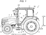
- Fig. 1 is an explanatory view of the working vehicle 1 according to the embodiment, and is a schematic left side view of the working vehicle 1.
- a tractor will be described as an example of the working vehicle 1.
- the tractor 1 is an agricultural tractor that is self-propelled by automatic operation and works in a field or the like. As will be described later, when turning near a shore of a field, the tractor 1 controls a transmission (not shown) to enable a suitable turning travel. The tractor 1 can carry out a predetermined work while an operator (also referred to as a worker) is boarding and running in a field.
- a front and rear direction of the tractor 1 refers to a straight direction of the tractor 1. Further, in the straight direction of the tractor 1, a direction going from a driver's seat 8 to a steering wheel 9 is a forward direction of the tractor 1, and an opposite direction thereof is a reverse (backward) direction. Further, the front and rear of the tractor 1 are based on the forward direction.
- a left and right direction refers to a direction that is horizontally orthogonal to the front and rear direction.
- the left and right are defined toward the "front" side in the front and rear direction. That is, with an operator seated in the driver's seat 8 and facing forward, his left hand side is “left”, and his right hand side is “right.”
- an upper and lower direction refers to a direction that is orthogonal to the front and rear direction and the left and right direction.
- the front and rear direction, the left and right direction, and the upper and lower direction are three-dimensionally orthogonal to each other.
- the tractor 1 includes a cabin 11, a running vehicle body F, front wheels 2 and rear wheels 3 provided on the running vehicle body F and serving as running devices, an engine 4 as a driving source, a bonnet 6 covering the engine 4, a connecting device 7 for connecting a working machine, a transmission case 12 for accommodating a transmission, and a fuel tank 13 provided below the cabin 11.
- the front wheels 2 are provided as a pair of left and right wheels.
- the front wheels 2 are rotatably connected to a front axle 2a and mainly serve as steered wheels.
- the rear wheels 3 are provided as a pair of left and right wheels.
- the rear wheels 3 are rotatably connected to a rear axle 3a and mainly serve as driving wheels.
- the running mode of the tractor 1 can be switched to a two-wheel drive (2WD) mode in which the rear wheels 3 are driven via a transmission, a four-wheel drive (4WD) mode in which both the front wheels 2 and the rear wheels 3 are driven, and a front wheel acceleration mode in which the front wheels 2 are accelerated.
- 2WD two-wheel drive
- 4WD four-wheel drive
- front wheel acceleration mode in which the front wheels 2 are accelerated.
- both the front wheels 2 and the rear wheels 3 serve as driving wheels.
- the bonnet 6 can pivot (can be opened and closed) in the upper and lower direction with a rear portion as a pivot center.
- the bonnet 6 in a closed state covers the engine 4 mounted on a vehicle body frame.
- the engine 4 is a drive source of the tractor 1 and is a heat engine such as a diesel engine or a gasoline engine.
- An operation part in which a driver is located is provided inside the cabin 11.
- the operation part is provided on the running vehicle body F.
- the driver's seat 8, the steering wheel 9, a forward and backward pedal 14 for moving the running vehicle body F forward or backward, a floor 15 serving as a floor surface of the operation part, various levers (not shown) such as a shift lever and an auxiliary shift lever, and various pedals (not shown) such as an accelerator pedal, a brake pedal and a clutch pedal are provided in the operation part.
- the operation part may be in a released state where it is not covered by the cabin 11.
- the driver's seat 8 is a seat for a driver provided on the running vehicle body F.
- the steering wheel 9 can be operated by a driver to steer the front wheels 2 that are steered wheels.
- the steering wheel 9 is provided on a dashboard 10 provided in front of the driver's seat 8.
- a display unit (meter panel) for displaying various types of information is provided on an upper surface of the dashboard 10.
- the forward and backward pedal 14 is an operation pedal that is coupled to a trunnion shaft (see Fig. 2 ) connected to the transmission and provided for switching the transmission between a neutral position, a forward movement and a rearward movement.
- the forward and backward pedal 14 has a pivot shaft 142 (see Fig. 2 ) provided on a floor bracket 151 (see Fig. 2 ) between the floor 15 and the fuel tank 13.
- the transmission case 12 accommodates the transmission.
- the transmission appropriately decelerates power (rotational power) transmitted from the engine 4 and transmits the power to the front wheels 2 and the rear wheels 3 serving as drive wheels, and a PTO (Power Take-off) shaft (not shown).
- the transmission is, for example, a hydrostatic continuously variable transmission.
- a working machine that works in the field can be coupled to a rear portion of the tractor 1 via the connecting device 7.
- the working machine is driven by a PTO shaft (not shown) protruding rearward from the transmission case 12.
- the PTO shaft transmits, to the working machine, the rotational power that is appropriately decelerated by the transmission.
- the working machine is lifted and lowered by a lifting device (not shown).
- the working machine is in a non-working position when lifted and is in a ground working position when lowered.
- a seeding transplanting machine for transplanting seeding in a paddy field a rotary cultivator for cultivating fields, and the like are appropriately connected.
- a transplant claw rotates by the power transmitted from the PTO shaft to transplant seeding in a field surface.
- a cultivating claw rotates by the power transmitted from the PTO shaft to cultivate a field surface (soil).
- the tractor 1 includes a positioning device (not shown) that functions as a position information acquisition device for acquiring position information of an own vehicle.
- the positioning device can measure the position of the own vehicle.
- the positioning device is, for example, a GNSS (Global Navigation Satellite System).
- a reception antenna 320 constituting a part of the positioning device is provided at a front portion of the cabin 11.
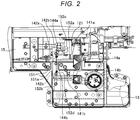
- Fig. 2 is a top view of the periphery of the floor 15 including the forward and backward pedal 14
- Fig. 3 is a side view of the periphery of the floor 15 including the forward and backward pedal 14
- Fig. 4 is a perspective view of the periphery of the floor including the forward and backward pedal.
- the right side of the drawing is the front direction of the tractor 1
- the left side of the drawing is the rear direction of the tractor 1.
- the floor 15 is shown in a transparent state.
- the forward and backward pedal 14 includes pedal portions 14a, 14b, arm portions 141a, 141b, pivot shafts 142a, 142b, link mechanisms 143a, 143b, and a grease nipple 144.
- the pedal portions 14a, 14b are members that are operated (depressed) by a driver.
- the forward pedal portion 14a is arranged on the left side
- the backward pedal portion 14b is arranged on the right side.
- the forward pedal portion 14a may be arranged on the right side
- the backward pedal portion 14b may be arranged on the left side.
- the arm portions 141a, 141b are members for connecting the pedal portions 14a, 14b and the pivot shafts 142a, 142b. Specifically, the arm portions 141a, 141b are connected to the pedal portions 14a, 14b above the floor 15, extend to the lower side of the floor 15 through hole portions 152a, 152b of the floor 15, and are connected to the pivot shaft 142 below the floor 15.
- the two arm portions 141a, 141b are independently connected to the two pedal portions 14a, 14b, respectively. Specifically, the first arm portion 141a connects the forward pedal portion 14a and the first pivot shaft 142a. The second arm portion 141b connects the backward pedal portion 14b and the second pivot shaft 142b.
- the two pivot shafts 142a, 142b are arranged on a straight line and are provided on the floor bracket 151.
- the two pivot shafts 142a, 142b are configured to pivot integrally with the arm portions 141a, 141b.
- the first pivot shaft 142a pivots together with the first arm portion 141a by an amount corresponding to a depressing force when the pedal portion 14a is depressed by a driver.
- the second pivot shaft 142b pivots together with the second arm portion 141b by an amount corresponding to a depressing force when the pedal portion 14b is depressed by a driver.
- the second pivot shaft 142b passes, for example, through the inside of the first pivot shaft 142a and the inside of a cylindrical shaft fixing portion 151a provided on the floor bracket 151, and can pivot independently of the first pivot shaft 142a. That is, the first pivot shaft 142a and the second pivot shaft 142b are pivot shafts having the same center position (are coaxial).
- the pedal 14 can be compactly arranged.
- the link mechanisms 143a, 143b are members for connecting the pivot shafts 142a, 142b and arm portions 122a, 122b of a trunnion shaft 121.
- the link mechanisms 143a, 143b are substantially L-shaped members. One ends of the link mechanisms 143a, 143b are connected to the pivot shafts 142a, 142b, and the other ends are connected to the arm portions 122a, 122b.
- the first link mechanism 143a is arranged below the pivot shafts 142a, 142b and the trunnion shaft 121 and is configured to be convex downward. Further, the first pivot shaft 142a is fixed to one end of the first link mechanism 143a, and the first arm portion 122a is pivotably connected to the other end of the first link mechanism 143a.
- first link mechanism 143a has an L-shape and is configured such that a portion where two sides of the L-shape overlap is pivotable. Further, the first arm portion 122a is fixedly connected to the trunnion shaft 121.
- the second link mechanism 143b is arranged between the pivot shafts 142a, 142b and the trunnion shaft 121 and is configured to be convex upward. Further, the second pivot shaft 142b is fixed to one end of the second link mechanism 143b, and the second arm portion 122b is pivotably connected to the other end of the second link mechanism 143b.
- the second link mechanism 143b has an L-shape and is configured such that a portion where two sides of the L-shape overlap is pivotable. Further, the second arm portion 122b is fixedly connected to the trunnion shaft 121.
- connection portion between the second link mechanism 143b and the second arm portion 122b is located close to the floor 15. In other words, there is a possibility that the connection portion and the floor 15 may contact in the operation range of the second arm portion 122b.
- the floor 15 has a hole portion 152c provided at a position corresponding to the operation range of the second arm portion 122b.
- the second arm portion 122b passes through the hole portion 152c when it is operated.
- the position of the floor 15 corresponding to the operation range of the second arm portion 122b may be configured to have a convex shape.
- the pedal 14 is provided with grease nipples 144a, 144b for supplying grease to the pivot shafts 142a, 142b.
- first grease nipple 144a is a portion that is provided on the first pivot shaft 142a and configured to supply grease to the first pivot shaft 142a.
- the second grease nipple 144b is a portion that is provided on the second pivot shaft 142b and configured to supply grease to the second pivot shaft 142b.
- the two grease nipples 144a, 144b are arranged, for example, facing obliquely forward. Further, a part of the hole portion 152a and a hole portion 152d are provided at positions of the floor 15 corresponding to the grease nipples 144a, 144b. In this way, an operator (driver or the like) can easily supply grease to the pivot shafts 142a, 142b.
- the tractor 1 includes the running vehicle body F, the floor 15 provided on the running vehicle body F and serving as a floor surface of the operation part in which a driver is located, the floor bracket 151 configured to support the floor 15, and the fuel tank 13 provided below the floor 15.
- the tractor 1 includes the pedal 14 configured to move the running vehicle body F forward or backward and having the pivot shafts 142a, 142b provided on the floor bracket 151 between the floor 15 and the fuel tank 13. In this way, the pedal 14 can be compactly arranged.
- the pedal 14 is provided with the grease nipples 144a, 144b for supplying grease to the pivot shafts 142a, 142b.
- the floor 15 is provided with the hole portions at positions corresponding to the grease nipples 144a, 144b. In this way, an operator can easily supply grease to the pivot shafts 142a, 142b.
- the tractor 1 further includes the hydrostatic continuously variable transmission having the trunnion shaft 121 provided below the floor 15.
- the trunnion shaft 121 is connected to the arm portions 122a, 122b.
- the pedal 14 includes the link mechanisms 143a, 143b that connect the arm portions 122a, 122b and the pivot shafts 142a, 142b.
- the floor 15 has the hole portion 152c at a position corresponding to the operation range of the arm portions 122a, 122b. In this way, it is possible to avoid interference between the arm portion 122a and the floor 15 due to contact or the like.
- a tractor (1) includes a running vehicle body (F), a floor (15) provided on the running vehicle body (F) and serving as a floor surface of an operation part in which a driver is located, a floor bracket (151) configured to support the floor (15), a fuel tank (13) provided below the floor (15), and a pedal (14) configured to move the running vehicle body (F) forward or backward and having pivot shafts (142a, 142b) provided on the floor bracket (151) between the floor (15) and the fuel tank (13).
Landscapes
- Engineering & Computer Science (AREA)
- Chemical & Material Sciences (AREA)
- Combustion & Propulsion (AREA)
- Transportation (AREA)
- Mechanical Engineering (AREA)
- Life Sciences & Earth Sciences (AREA)
- Sustainable Development (AREA)
- Sustainable Energy (AREA)
- Arrangement Or Mounting Of Control Devices For Change-Speed Gearing (AREA)
- Cooling, Air Intake And Gas Exhaust, And Fuel Tank Arrangements In Propulsion Units (AREA)
Abstract
Description
- The invention relates to a working vehicle.
- There are working vehicles such as tractors in which an arm portion of a pedal is connected to a pivot shaft disposed below a floor and the pivot shaft is inclined so as to approach the rear of a vehicle body toward the side of the vehicle body (e.g., see
JP-A-2017-178044 - By the way, recently, in a working vehicle such as a tractor, an exhaust gas treatment device may be arranged inside a bonnet and an installation position of a fuel tank may be displaced from the inside of the bonnet to the lower side of a floor in connection with exhaust gas regulations. In this configuration, it may be difficult to place a pedal as in the related art.
- The invention has been made in view of the above situations, and an object thereof is to provide a working vehicle in which a pedal can be compactly arranged.
- In order to solve the above problems and achieve the object, a working vehicle (1) according to one aspect of the embodiment includes a running vehicle body (F), a floor (15) provided on the running vehicle body (F) and serving as a floor surface of an operation part in which a driver is located, a floor bracket (151) configured to support the floor (15), and a fuel tank (13) provided below the floor (15). The working vehicle (1) includes a pedal (14) configured to move the running vehicle body (F) forward or backward and having pivot shafts (142a, 142b) provided on the floor bracket (151) between the floor (15) and the fuel tank (13).
- According to one aspect of the embodiment, the pedal can be compactly arranged.
-
-
Fig. 1 is an explanatory view of a working vehicle according to an embodiment, and is a schematic left side view of the working vehicle; -
Fig. 2 is a top view of a periphery of a floor including a forward and backward pedal; -
Fig. 3 is a side view of the periphery of the floor including the forward and backward pedal; and -
Fig. 4 is a perspective view of the periphery of the floor including the forward and backward pedal. - Hereinafter, an embodiment of a working vehicle disclosed in the present application will be described in detail with reference to the accompanying drawings. The invention is not limited to the embodiment described below.
- First, the overall configuration of a working vehicle 1 according to an embodiment will be described with reference to
Fig. 1. Fig. 1 is an explanatory view of the working vehicle 1 according to the embodiment, and is a schematic left side view of the working vehicle 1. In the following, a tractor will be described as an example of the working vehicle 1. - The tractor 1 is an agricultural tractor that is self-propelled by automatic operation and works in a field or the like. As will be described later, when turning near a shore of a field, the tractor 1 controls a transmission (not shown) to enable a suitable turning travel. The tractor 1 can carry out a predetermined work while an operator (also referred to as a worker) is boarding and running in a field.
- In the following, a front and rear direction of the tractor 1 refers to a straight direction of the tractor 1. Further, in the straight direction of the tractor 1, a direction going from a driver's
seat 8 to asteering wheel 9 is a forward direction of the tractor 1, and an opposite direction thereof is a reverse (backward) direction. Further, the front and rear of the tractor 1 are based on the forward direction. - Further, a left and right direction refers to a direction that is horizontally orthogonal to the front and rear direction. Here, the left and right are defined toward the "front" side in the front and rear direction. That is, with an operator seated in the driver's
seat 8 and facing forward, his left hand side is "left", and his right hand side is "right." Furthermore, an upper and lower direction refers to a direction that is orthogonal to the front and rear direction and the left and right direction. Thus, the front and rear direction, the left and right direction, and the upper and lower direction are three-dimensionally orthogonal to each other. - As shown in
Fig. 1 , the tractor 1 includes acabin 11, a running vehicle body F,front wheels 2 and rear wheels 3 provided on the running vehicle body F and serving as running devices, anengine 4 as a driving source, abonnet 6 covering theengine 4, a connecting device 7 for connecting a working machine, atransmission case 12 for accommodating a transmission, and afuel tank 13 provided below thecabin 11. - The
front wheels 2 are provided as a pair of left and right wheels. Thefront wheels 2 are rotatably connected to afront axle 2a and mainly serve as steered wheels. The rear wheels 3 are provided as a pair of left and right wheels. The rear wheels 3 are rotatably connected to arear axle 3a and mainly serve as driving wheels. - The running mode of the tractor 1 can be switched to a two-wheel drive (2WD) mode in which the rear wheels 3 are driven via a transmission, a four-wheel drive (4WD) mode in which both the
front wheels 2 and the rear wheels 3 are driven, and a front wheel acceleration mode in which thefront wheels 2 are accelerated. In the case of the 4WD mode or the front wheel acceleration mode, both thefront wheels 2 and the rear wheels 3 serve as driving wheels. - The
bonnet 6 can pivot (can be opened and closed) in the upper and lower direction with a rear portion as a pivot center. Thebonnet 6 in a closed state covers theengine 4 mounted on a vehicle body frame. Theengine 4 is a drive source of the tractor 1 and is a heat engine such as a diesel engine or a gasoline engine. - An operation part in which a driver is located is provided inside the
cabin 11. The operation part is provided on the running vehicle body F. The driver'sseat 8, thesteering wheel 9, a forward and backwardpedal 14 for moving the running vehicle body F forward or backward, afloor 15 serving as a floor surface of the operation part, various levers (not shown) such as a shift lever and an auxiliary shift lever, and various pedals (not shown) such as an accelerator pedal, a brake pedal and a clutch pedal are provided in the operation part. The operation part may be in a released state where it is not covered by thecabin 11. - The driver's
seat 8 is a seat for a driver provided on the running vehicle body F. Thesteering wheel 9 can be operated by a driver to steer thefront wheels 2 that are steered wheels. Thesteering wheel 9 is provided on adashboard 10 provided in front of the driver'sseat 8. A display unit (meter panel) for displaying various types of information is provided on an upper surface of thedashboard 10. - The forward and
backward pedal 14 is an operation pedal that is coupled to a trunnion shaft (seeFig. 2 ) connected to the transmission and provided for switching the transmission between a neutral position, a forward movement and a rearward movement. As will be described in detail later, the forward and backwardpedal 14 has a pivot shaft 142 (seeFig. 2 ) provided on a floor bracket 151 (seeFig. 2 ) between thefloor 15 and thefuel tank 13. - The
transmission case 12 accommodates the transmission. The transmission appropriately decelerates power (rotational power) transmitted from theengine 4 and transmits the power to thefront wheels 2 and the rear wheels 3 serving as drive wheels, and a PTO (Power Take-off) shaft (not shown). The transmission is, for example, a hydrostatic continuously variable transmission. - A working machine (not shown) that works in the field can be coupled to a rear portion of the tractor 1 via the connecting device 7. The working machine is driven by a PTO shaft (not shown) protruding rearward from the
transmission case 12. - The PTO shaft transmits, to the working machine, the rotational power that is appropriately decelerated by the transmission. The working machine is lifted and lowered by a lifting device (not shown). The working machine is in a non-working position when lifted and is in a ground working position when lowered.
- As the working machine, for example, a seeding transplanting machine for transplanting seeding in a paddy field, a rotary cultivator for cultivating fields, and the like are appropriately connected. In the seeding transplanting machine, a transplant claw (not shown) rotates by the power transmitted from the PTO shaft to transplant seeding in a field surface. Further, in the rotary cultivator, a cultivating claw (not shown) rotates by the power transmitted from the PTO shaft to cultivate a field surface (soil).
- Further, the tractor 1 includes a positioning device (not shown) that functions as a position information acquisition device for acquiring position information of an own vehicle. The positioning device can measure the position of the own vehicle. The positioning device is, for example, a GNSS (Global Navigation Satellite System). As shown in
Fig. 1 , areception antenna 320 constituting a part of the positioning device is provided at a front portion of thecabin 11. - Subsequently, the arrangement of the forward and
backward pedal 14 will be described in detail with reference toFigs. 2 to 4 .Fig. 2 is a top view of the periphery of thefloor 15 including the forward andbackward pedal 14,Fig. 3 is a side view of the periphery of thefloor 15 including the forward andbackward pedal 14, andFig. 4 is a perspective view of the periphery of the floor including the forward and backward pedal. InFigs. 2 and3 , the right side of the drawing is the front direction of the tractor 1, and the left side of the drawing is the rear direction of the tractor 1. InFigs. 2 to 4 , in order to facilitate understanding, thefloor 15 is shown in a transparent state. - As shown in
Figs. 2 ,3 and4 , the forward andbackward pedal 14 includespedal portions arm portions pivot shafts link mechanisms - The
pedal portions Fig. 2 , theforward pedal portion 14a is arranged on the left side, and thebackward pedal portion 14b is arranged on the right side. Theforward pedal portion 14a may be arranged on the right side, and thebackward pedal portion 14b may be arranged on the left side. - The
arm portions pedal portions pivot shafts arm portions pedal portions floor 15, extend to the lower side of thefloor 15 throughhole portions floor 15, and are connected to the pivot shaft 142 below thefloor 15. - The two
arm portions pedal portions first arm portion 141a connects theforward pedal portion 14a and thefirst pivot shaft 142a. Thesecond arm portion 141b connects thebackward pedal portion 14b and thesecond pivot shaft 142b. - The two
pivot shafts floor bracket 151. The twopivot shafts arm portions first pivot shaft 142a pivots together with thefirst arm portion 141a by an amount corresponding to a depressing force when thepedal portion 14a is depressed by a driver. - Further, the
second pivot shaft 142b pivots together with thesecond arm portion 141b by an amount corresponding to a depressing force when thepedal portion 14b is depressed by a driver. - More specifically, the
second pivot shaft 142b passes, for example, through the inside of thefirst pivot shaft 142a and the inside of a cylindricalshaft fixing portion 151a provided on thefloor bracket 151, and can pivot independently of thefirst pivot shaft 142a. That is, thefirst pivot shaft 142a and thesecond pivot shaft 142b are pivot shafts having the same center position (are coaxial). - In this way, when the
pivot shafts floor bracket 151, a dedicated member for providing thepivot shafts - The
link mechanisms pivot shafts arm portions trunnion shaft 121. Specifically, thelink mechanisms link mechanisms pivot shafts arm portions - Specifically, the
first link mechanism 143a is arranged below thepivot shafts trunnion shaft 121 and is configured to be convex downward. Further, thefirst pivot shaft 142a is fixed to one end of thefirst link mechanism 143a, and thefirst arm portion 122a is pivotably connected to the other end of thefirst link mechanism 143a. - Further, the
first link mechanism 143a has an L-shape and is configured such that a portion where two sides of the L-shape overlap is pivotable. Further, thefirst arm portion 122a is fixedly connected to thetrunnion shaft 121. - In this way, when the
first pedal portion 14a is depressed, a depressing force is transmitted to thetrunnion shaft 121 via thefirst pivot shaft 142a, thefirst link mechanism 143a, and thefirst arm portion 122a. Thereby, thetrunnion shaft 121 pivots. - Further, the
second link mechanism 143b is arranged between thepivot shafts trunnion shaft 121 and is configured to be convex upward. Further, thesecond pivot shaft 142b is fixed to one end of thesecond link mechanism 143b, and thesecond arm portion 122b is pivotably connected to the other end of thesecond link mechanism 143b. - Further, the
second link mechanism 143b has an L-shape and is configured such that a portion where two sides of the L-shape overlap is pivotable. Further, thesecond arm portion 122b is fixedly connected to thetrunnion shaft 121. - In this way, when the
second pedal portion 14b is depressed, a depressing force is transmitted to thetrunnion shaft 121 via thesecond pivot shaft 142b, thesecond link mechanism 143b, and thesecond arm portion 122b. Thereby, thetrunnion shaft 121 pivots. - Further, as shown in
Fig. 3 , a connection portion between thesecond link mechanism 143b and thesecond arm portion 122b is located close to thefloor 15. In other words, there is a possibility that the connection portion and thefloor 15 may contact in the operation range of thesecond arm portion 122b. - Therefore, the
floor 15 has ahole portion 152c provided at a position corresponding to the operation range of thesecond arm portion 122b. In this way, thesecond arm portion 122b passes through thehole portion 152c when it is operated. As a result, it is possible to prevent thesecond arm portion 122b and thefloor 15 from coming into contact with each other and interfering with each other. Instead of the hole portion, the position of thefloor 15 corresponding to the operation range of thesecond arm portion 122b may be configured to have a convex shape. - Further, as shown in
Fig. 2 , thepedal 14 is provided withgrease nipples pivot shafts - Specifically, the
first grease nipple 144a is a portion that is provided on thefirst pivot shaft 142a and configured to supply grease to thefirst pivot shaft 142a. Thesecond grease nipple 144b is a portion that is provided on thesecond pivot shaft 142b and configured to supply grease to thesecond pivot shaft 142b. - Further, the two
grease nipples hole portion 152a and ahole portion 152d are provided at positions of thefloor 15 corresponding to thegrease nipples pivot shafts - As described above, the tractor 1 according to the embodiment includes the running vehicle body F, the
floor 15 provided on the running vehicle body F and serving as a floor surface of the operation part in which a driver is located, thefloor bracket 151 configured to support thefloor 15, and thefuel tank 13 provided below thefloor 15. The tractor 1 includes the pedal 14 configured to move the running vehicle body F forward or backward and having thepivot shafts floor bracket 151 between thefloor 15 and thefuel tank 13. In this way, the pedal 14 can be compactly arranged. - Further, the
pedal 14 is provided with thegrease nipples pivot shafts floor 15 is provided with the hole portions at positions corresponding to thegrease nipples pivot shafts - Further, the tractor 1 further includes the hydrostatic continuously variable transmission having the
trunnion shaft 121 provided below thefloor 15. Thetrunnion shaft 121 is connected to thearm portions pedal 14 includes thelink mechanisms arm portions pivot shafts floor 15 has thehole portion 152c at a position corresponding to the operation range of thearm portions arm portion 122a and thefloor 15 due to contact or the like. - Further effects and modifications can be easily derived by those skilled in the art. Therefore, the broader aspects of the invention are not limited to the particular details and representative embodiments shown and described above. In this way, various changes can be made without departing from the gist or scope of the general inventive concepts as defined by the appended claims and their equivalents.
- A tractor (1) according to one aspect of the embodiment includes a running vehicle body (F), a floor (15) provided on the running vehicle body (F) and serving as a floor surface of an operation part in which a driver is located, a floor bracket (151) configured to support the floor (15), a fuel tank (13) provided below the floor (15), and a pedal (14) configured to move the running vehicle body (F) forward or backward and having pivot shafts (142a, 142b) provided on the floor bracket (151) between the floor (15) and the fuel tank (13).
- 1
- Tractor (Working vehicle)
- 2
- Front wheel
- 3
- Rear wheel
- 4
- Engine
- 6
- Bonnet
- 7
- Connecting device
- 8
- Driver's seat
- 9
- Steering wheel
- 10
- Dashboard
- 11
- Cabin
- 12
- Transmission case
- 13
- Fuel tank
- 14
- Forward and backward pedal
- 15
- Floor
- 121
- Trunnion shaft
- 142
- Pivot shaft
- 151
- Floor bracket
- F
- Running vehicle body
Claims (3)
- A working vehicle comprising:a running vehicle body (F);a floor (15) provided on the running vehicle body (F) and serving as a floor surface of an operation part in which a driver is located;a floor bracket (151) configured to support the floor (15) ;a fuel tank (13) provided below the floor (15); anda pedal (14) configured to move the running vehicle body (F) forward or backward and comprising pivot shafts (142a, 142b) provided on the floor bracket (151) between the floor (15) and the fuel tank (13).
- The working vehicle according to claim 1,
wherein the pedal (14) is provided with grease nipples (144a, 144b) for supplying grease to the pivot shafts (142a, 142b), and
wherein the floor (15) is provided with hole portions (152a, 152d) at positions corresponding to the grease nipples (144a, 144b). - The working vehicle according to claim 1 or 2, further comprising:a hydrostatic continuously variable transmission comprising a trunnion shaft (121) provided below the floor (15),wherein the trunnion shaft (121) is connected to an arm portion (122b),wherein the pedal (14) comprises a link mechanism (143b) that connects the arm portion (122b) and the pivot shaft (142b), andwherein the floor (15) has a hole portion (152c) at a position corresponding to the operation range of the arm portion (122b).
Applications Claiming Priority (1)
| Application Number | Priority Date | Filing Date | Title |
|---|---|---|---|
| JP2019236886A JP7031652B2 (en) | 2019-12-26 | 2019-12-26 | Work vehicle |
Publications (2)
| Publication Number | Publication Date |
|---|---|
| EP3842273A1 true EP3842273A1 (en) | 2021-06-30 |
| EP3842273B1 EP3842273B1 (en) | 2022-07-20 |
Family
ID=72709042
Family Applications (1)
| Application Number | Title | Priority Date | Filing Date |
|---|---|---|---|
| EP20199167.6A Active EP3842273B1 (en) | 2019-12-26 | 2020-09-30 | Working vehicle |
Country Status (3)
| Country | Link |
|---|---|
| US (1) | US11607955B2 (en) |
| EP (1) | EP3842273B1 (en) |
| JP (1) | JP7031652B2 (en) |
Citations (4)
| Publication number | Priority date | Publication date | Assignee | Title |
|---|---|---|---|---|
| JP2007190967A (en) * | 2006-01-17 | 2007-08-02 | Yanmar Co Ltd | Working vehicle |
| WO2012035981A1 (en) * | 2010-09-14 | 2012-03-22 | ヤンマー株式会社 | Work vehicle |
| US20170225622A1 (en) * | 2016-02-05 | 2017-08-10 | Iseki & Co., Ltd. | Working vehicle |
| JP2017178044A (en) | 2016-03-30 | 2017-10-05 | ヤンマー株式会社 | Work vehicle |
Family Cites Families (13)
| Publication number | Priority date | Publication date | Assignee | Title |
|---|---|---|---|---|
| EP1439110A3 (en) * | 2003-01-16 | 2004-11-03 | Mazda Motor Corporation | Floor panel structure of vehicle body |
| JP2006160078A (en) * | 2004-12-07 | 2006-06-22 | Iseki & Co Ltd | Work vehicle fuel tank |
| US20070138863A1 (en) * | 2005-11-01 | 2007-06-21 | Warren Clark | Modular Pedal Box Assembly |
| JP4934401B2 (en) * | 2006-10-25 | 2012-05-16 | ヤンマー株式会社 | Work vehicle with cabin |
| FR2957888B1 (en) * | 2010-03-29 | 2012-03-23 | Renault Sa | VEHICLE AND SUPPORT FOR ENERGY TANK |
| US9317058B2 (en) * | 2013-10-18 | 2016-04-19 | Yanmar Co., Ltd. | Pedal assembly module |
| KR20160140587A (en) * | 2014-03-28 | 2016-12-07 | 얀마 가부시키가이샤 | Work vehicle |
| KR102140360B1 (en) * | 2014-03-28 | 2020-08-03 | 얀마 파워 테크놀로지 가부시키가이샤 | Industrial vehicle |
| JP6398446B2 (en) * | 2014-08-08 | 2018-10-03 | 井関農機株式会社 | Tractor |
| JP6230515B2 (en) * | 2014-09-26 | 2017-11-15 | 株式会社クボタ | Work vehicle |
| JP6471464B2 (en) * | 2014-11-07 | 2019-02-20 | 井関農機株式会社 | Work vehicle |
| JP6487822B2 (en) * | 2015-11-05 | 2019-03-20 | ヤンマー株式会社 | Tractor |
| US10422426B2 (en) * | 2016-11-15 | 2019-09-24 | Kubota Corporation | Assembly for regulating ground speed of vehicle |
-
2019
- 2019-12-26 JP JP2019236886A patent/JP7031652B2/en active Active
-
2020
- 2020-09-30 EP EP20199167.6A patent/EP3842273B1/en active Active
- 2020-10-14 US US17/070,364 patent/US11607955B2/en active Active
Patent Citations (4)
| Publication number | Priority date | Publication date | Assignee | Title |
|---|---|---|---|---|
| JP2007190967A (en) * | 2006-01-17 | 2007-08-02 | Yanmar Co Ltd | Working vehicle |
| WO2012035981A1 (en) * | 2010-09-14 | 2012-03-22 | ヤンマー株式会社 | Work vehicle |
| US20170225622A1 (en) * | 2016-02-05 | 2017-08-10 | Iseki & Co., Ltd. | Working vehicle |
| JP2017178044A (en) | 2016-03-30 | 2017-10-05 | ヤンマー株式会社 | Work vehicle |
Also Published As
| Publication number | Publication date |
|---|---|
| US11607955B2 (en) | 2023-03-21 |
| JP7031652B2 (en) | 2022-03-08 |
| US20210197663A1 (en) | 2021-07-01 |
| JP2021104741A (en) | 2021-07-26 |
| EP3842273B1 (en) | 2022-07-20 |
Similar Documents
| Publication | Publication Date | Title |
|---|---|---|
| KR102761119B1 (en) | work vehicle | |
| EP3421283B1 (en) | Work vehicle | |
| JP2025063221A (en) | Work vehicles | |
| EP3842273B1 (en) | Working vehicle | |
| KR870001853Y1 (en) | Driving control devices of a tractor | |
| US4147227A (en) | Standard model tractor with removable second set of operating controls | |
| JP2021165064A (en) | Work vehicle | |
| JP2021094964A (en) | Work vehicle | |
| JP7396232B2 (en) | work vehicle | |
| JP2002325504A (en) | Management vehicle | |
| KR20220059402A (en) | Working vehicle | |
| JP7396234B2 (en) | work vehicle | |
| EP4257400B1 (en) | Work vehicle | |
| JP3904303B2 (en) | Shift operating device for work vehicle | |
| JPH02274627A (en) | Pto shaft device for tractor | |
| US11370289B2 (en) | Work vehicle | |
| JP5063569B2 (en) | Work vehicle | |
| JP2023101048A (en) | work vehicle | |
| JP3661218B2 (en) | Passenger management machine transmission | |
| JP2003080964A (en) | PTO operating device for tractor | |
| JP2026019291A (en) | Work vehicles | |
| JPH0534423Y2 (en) | ||
| JPS6222417Y2 (en) | ||
| JP2015009794A (en) | Tractor | |
| JP2003219714A (en) | Operation lever positioning mechanism |
Legal Events
| Date | Code | Title | Description |
|---|---|---|---|
| PUAI | Public reference made under article 153(3) epc to a published international application that has entered the european phase |
Free format text: ORIGINAL CODE: 0009012 |
|
| STAA | Information on the status of an ep patent application or granted ep patent |
Free format text: STATUS: THE APPLICATION HAS BEEN PUBLISHED |
|
| AK | Designated contracting states |
Kind code of ref document: A1 Designated state(s): AL AT BE BG CH CY CZ DE DK EE ES FI FR GB GR HR HU IE IS IT LI LT LU LV MC MK MT NL NO PL PT RO RS SE SI SK SM TR |
|
| STAA | Information on the status of an ep patent application or granted ep patent |
Free format text: STATUS: REQUEST FOR EXAMINATION WAS MADE |
|
| 17P | Request for examination filed |
Effective date: 20211223 |
|
| RBV | Designated contracting states (corrected) |
Designated state(s): AL AT BE BG CH CY CZ DE DK EE ES FI FR GB GR HR HU IE IS IT LI LT LU LV MC MK MT NL NO PL PT RO RS SE SI SK SM TR |
|
| GRAP | Despatch of communication of intention to grant a patent |
Free format text: ORIGINAL CODE: EPIDOSNIGR1 |
|
| STAA | Information on the status of an ep patent application or granted ep patent |
Free format text: STATUS: GRANT OF PATENT IS INTENDED |
|
| RIC1 | Information provided on ipc code assigned before grant |
Ipc: B60K 17/10 20060101ALI20220111BHEP Ipc: B60K 15/063 20060101ALI20220111BHEP Ipc: B60K 26/02 20060101AFI20220111BHEP |
|
| INTG | Intention to grant announced |
Effective date: 20220209 |
|
| GRAS | Grant fee paid |
Free format text: ORIGINAL CODE: EPIDOSNIGR3 |
|
| GRAA | (expected) grant |
Free format text: ORIGINAL CODE: 0009210 |
|
| STAA | Information on the status of an ep patent application or granted ep patent |
Free format text: STATUS: THE PATENT HAS BEEN GRANTED |
|
| AK | Designated contracting states |
Kind code of ref document: B1 Designated state(s): AL AT BE BG CH CY CZ DE DK EE ES FI FR GB GR HR HU IE IS IT LI LT LU LV MC MK MT NL NO PL PT RO RS SE SI SK SM TR |
|
| REG | Reference to a national code |
Ref country code: CH Ref legal event code: EP |
|
| REG | Reference to a national code |
Ref country code: DE Ref legal event code: R096 Ref document number: 602020004081 Country of ref document: DE |
|
| REG | Reference to a national code |
Ref country code: AT Ref legal event code: REF Ref document number: 1505320 Country of ref document: AT Kind code of ref document: T Effective date: 20220815 |
|
| REG | Reference to a national code |
Ref country code: IE Ref legal event code: FG4D |
|
| REG | Reference to a national code |
Ref country code: LT Ref legal event code: MG9D |
|
| REG | Reference to a national code |
Ref country code: NL Ref legal event code: MP Effective date: 20220720 |
|
| PG25 | Lapsed in a contracting state [announced via postgrant information from national office to epo] |
Ref country code: SE Free format text: LAPSE BECAUSE OF FAILURE TO SUBMIT A TRANSLATION OF THE DESCRIPTION OR TO PAY THE FEE WITHIN THE PRESCRIBED TIME-LIMIT Effective date: 20220720 Ref country code: RS Free format text: LAPSE BECAUSE OF FAILURE TO SUBMIT A TRANSLATION OF THE DESCRIPTION OR TO PAY THE FEE WITHIN THE PRESCRIBED TIME-LIMIT Effective date: 20220720 Ref country code: PT Free format text: LAPSE BECAUSE OF FAILURE TO SUBMIT A TRANSLATION OF THE DESCRIPTION OR TO PAY THE FEE WITHIN THE PRESCRIBED TIME-LIMIT Effective date: 20221121 Ref country code: NO Free format text: LAPSE BECAUSE OF FAILURE TO SUBMIT A TRANSLATION OF THE DESCRIPTION OR TO PAY THE FEE WITHIN THE PRESCRIBED TIME-LIMIT Effective date: 20221020 Ref country code: NL Free format text: LAPSE BECAUSE OF FAILURE TO SUBMIT A TRANSLATION OF THE DESCRIPTION OR TO PAY THE FEE WITHIN THE PRESCRIBED TIME-LIMIT Effective date: 20220720 Ref country code: LV Free format text: LAPSE BECAUSE OF FAILURE TO SUBMIT A TRANSLATION OF THE DESCRIPTION OR TO PAY THE FEE WITHIN THE PRESCRIBED TIME-LIMIT Effective date: 20220720 Ref country code: LT Free format text: LAPSE BECAUSE OF FAILURE TO SUBMIT A TRANSLATION OF THE DESCRIPTION OR TO PAY THE FEE WITHIN THE PRESCRIBED TIME-LIMIT Effective date: 20220720 Ref country code: FI Free format text: LAPSE BECAUSE OF FAILURE TO SUBMIT A TRANSLATION OF THE DESCRIPTION OR TO PAY THE FEE WITHIN THE PRESCRIBED TIME-LIMIT Effective date: 20220720 Ref country code: ES Free format text: LAPSE BECAUSE OF FAILURE TO SUBMIT A TRANSLATION OF THE DESCRIPTION OR TO PAY THE FEE WITHIN THE PRESCRIBED TIME-LIMIT Effective date: 20220720 |
|
| REG | Reference to a national code |
Ref country code: AT Ref legal event code: MK05 Ref document number: 1505320 Country of ref document: AT Kind code of ref document: T Effective date: 20220720 |
|
| PG25 | Lapsed in a contracting state [announced via postgrant information from national office to epo] |
Ref country code: PL Free format text: LAPSE BECAUSE OF FAILURE TO SUBMIT A TRANSLATION OF THE DESCRIPTION OR TO PAY THE FEE WITHIN THE PRESCRIBED TIME-LIMIT Effective date: 20220720 Ref country code: IS Free format text: LAPSE BECAUSE OF FAILURE TO SUBMIT A TRANSLATION OF THE DESCRIPTION OR TO PAY THE FEE WITHIN THE PRESCRIBED TIME-LIMIT Effective date: 20221120 Ref country code: HR Free format text: LAPSE BECAUSE OF FAILURE TO SUBMIT A TRANSLATION OF THE DESCRIPTION OR TO PAY THE FEE WITHIN THE PRESCRIBED TIME-LIMIT Effective date: 20220720 Ref country code: GR Free format text: LAPSE BECAUSE OF FAILURE TO SUBMIT A TRANSLATION OF THE DESCRIPTION OR TO PAY THE FEE WITHIN THE PRESCRIBED TIME-LIMIT Effective date: 20221021 |
|
| REG | Reference to a national code |
Ref country code: DE Ref legal event code: R097 Ref document number: 602020004081 Country of ref document: DE |
|
| PG25 | Lapsed in a contracting state [announced via postgrant information from national office to epo] |
Ref country code: SM Free format text: LAPSE BECAUSE OF FAILURE TO SUBMIT A TRANSLATION OF THE DESCRIPTION OR TO PAY THE FEE WITHIN THE PRESCRIBED TIME-LIMIT Effective date: 20220720 Ref country code: RO Free format text: LAPSE BECAUSE OF FAILURE TO SUBMIT A TRANSLATION OF THE DESCRIPTION OR TO PAY THE FEE WITHIN THE PRESCRIBED TIME-LIMIT Effective date: 20220720 Ref country code: MC Free format text: LAPSE BECAUSE OF FAILURE TO SUBMIT A TRANSLATION OF THE DESCRIPTION OR TO PAY THE FEE WITHIN THE PRESCRIBED TIME-LIMIT Effective date: 20220720 Ref country code: DK Free format text: LAPSE BECAUSE OF FAILURE TO SUBMIT A TRANSLATION OF THE DESCRIPTION OR TO PAY THE FEE WITHIN THE PRESCRIBED TIME-LIMIT Effective date: 20220720 Ref country code: CZ Free format text: LAPSE BECAUSE OF FAILURE TO SUBMIT A TRANSLATION OF THE DESCRIPTION OR TO PAY THE FEE WITHIN THE PRESCRIBED TIME-LIMIT Effective date: 20220720 Ref country code: AT Free format text: LAPSE BECAUSE OF FAILURE TO SUBMIT A TRANSLATION OF THE DESCRIPTION OR TO PAY THE FEE WITHIN THE PRESCRIBED TIME-LIMIT Effective date: 20220720 |
|
| PLBE | No opposition filed within time limit |
Free format text: ORIGINAL CODE: 0009261 |
|
| STAA | Information on the status of an ep patent application or granted ep patent |
Free format text: STATUS: NO OPPOSITION FILED WITHIN TIME LIMIT |
|
| PG25 | Lapsed in a contracting state [announced via postgrant information from national office to epo] |
Ref country code: SK Free format text: LAPSE BECAUSE OF FAILURE TO SUBMIT A TRANSLATION OF THE DESCRIPTION OR TO PAY THE FEE WITHIN THE PRESCRIBED TIME-LIMIT Effective date: 20220720 Ref country code: EE Free format text: LAPSE BECAUSE OF FAILURE TO SUBMIT A TRANSLATION OF THE DESCRIPTION OR TO PAY THE FEE WITHIN THE PRESCRIBED TIME-LIMIT Effective date: 20220720 |
|
| 26N | No opposition filed |
Effective date: 20230421 |
|
| PG25 | Lapsed in a contracting state [announced via postgrant information from national office to epo] |
Ref country code: LU Free format text: LAPSE BECAUSE OF NON-PAYMENT OF DUE FEES Effective date: 20220930 Ref country code: AL Free format text: LAPSE BECAUSE OF FAILURE TO SUBMIT A TRANSLATION OF THE DESCRIPTION OR TO PAY THE FEE WITHIN THE PRESCRIBED TIME-LIMIT Effective date: 20220720 |
|
| PG25 | Lapsed in a contracting state [announced via postgrant information from national office to epo] |
Ref country code: IE Free format text: LAPSE BECAUSE OF NON-PAYMENT OF DUE FEES Effective date: 20220930 |
|
| PG25 | Lapsed in a contracting state [announced via postgrant information from national office to epo] |
Ref country code: SI Free format text: LAPSE BECAUSE OF FAILURE TO SUBMIT A TRANSLATION OF THE DESCRIPTION OR TO PAY THE FEE WITHIN THE PRESCRIBED TIME-LIMIT Effective date: 20220720 |
|
| PG25 | Lapsed in a contracting state [announced via postgrant information from national office to epo] |
Ref country code: CY Free format text: LAPSE BECAUSE OF FAILURE TO SUBMIT A TRANSLATION OF THE DESCRIPTION OR TO PAY THE FEE WITHIN THE PRESCRIBED TIME-LIMIT Effective date: 20220720 |
|
| REG | Reference to a national code |
Ref country code: CH Ref legal event code: PL |
|
| PG25 | Lapsed in a contracting state [announced via postgrant information from national office to epo] |
Ref country code: MK Free format text: LAPSE BECAUSE OF FAILURE TO SUBMIT A TRANSLATION OF THE DESCRIPTION OR TO PAY THE FEE WITHIN THE PRESCRIBED TIME-LIMIT Effective date: 20220720 Ref country code: IT Free format text: LAPSE BECAUSE OF FAILURE TO SUBMIT A TRANSLATION OF THE DESCRIPTION OR TO PAY THE FEE WITHIN THE PRESCRIBED TIME-LIMIT Effective date: 20220720 |
|
| PG25 | Lapsed in a contracting state [announced via postgrant information from national office to epo] |
Ref country code: CH Free format text: LAPSE BECAUSE OF NON-PAYMENT OF DUE FEES Effective date: 20230930 |
|
| PG25 | Lapsed in a contracting state [announced via postgrant information from national office to epo] |
Ref country code: HU Free format text: LAPSE BECAUSE OF FAILURE TO SUBMIT A TRANSLATION OF THE DESCRIPTION OR TO PAY THE FEE WITHIN THE PRESCRIBED TIME-LIMIT; INVALID AB INITIO Effective date: 20200930 Ref country code: CH Free format text: LAPSE BECAUSE OF NON-PAYMENT OF DUE FEES Effective date: 20230930 Ref country code: BG Free format text: LAPSE BECAUSE OF FAILURE TO SUBMIT A TRANSLATION OF THE DESCRIPTION OR TO PAY THE FEE WITHIN THE PRESCRIBED TIME-LIMIT Effective date: 20220720 |
|
| PG25 | Lapsed in a contracting state [announced via postgrant information from national office to epo] |
Ref country code: MT Free format text: LAPSE BECAUSE OF FAILURE TO SUBMIT A TRANSLATION OF THE DESCRIPTION OR TO PAY THE FEE WITHIN THE PRESCRIBED TIME-LIMIT Effective date: 20220720 |
|
| PGFP | Annual fee paid to national office [announced via postgrant information from national office to epo] |
Ref country code: BE Payment date: 20240920 Year of fee payment: 5 |
|
| PGFP | Annual fee paid to national office [announced via postgrant information from national office to epo] |
Ref country code: GB Payment date: 20250923 Year of fee payment: 6 |
|
| PGFP | Annual fee paid to national office [announced via postgrant information from national office to epo] |
Ref country code: FR Payment date: 20250924 Year of fee payment: 6 |
|
| PG25 | Lapsed in a contracting state [announced via postgrant information from national office to epo] |
Ref country code: TR Free format text: LAPSE BECAUSE OF FAILURE TO SUBMIT A TRANSLATION OF THE DESCRIPTION OR TO PAY THE FEE WITHIN THE PRESCRIBED TIME-LIMIT Effective date: 20220720 |
|
| PGFP | Annual fee paid to national office [announced via postgrant information from national office to epo] |
Ref country code: DE Payment date: 20250929 Year of fee payment: 6 |