EP3841853B1 - Rahmen für telekommunikationsausrüstung - Google Patents
Rahmen für telekommunikationsausrüstung Download PDFInfo
- Publication number
- EP3841853B1 EP3841853B1 EP19852770.7A EP19852770A EP3841853B1 EP 3841853 B1 EP3841853 B1 EP 3841853B1 EP 19852770 A EP19852770 A EP 19852770A EP 3841853 B1 EP3841853 B1 EP 3841853B1
- Authority
- EP
- European Patent Office
- Prior art keywords
- equipment
- splice
- cable
- frame
- assembly
- Prior art date
- Legal status (The legal status is an assumption and is not a legal conclusion. Google has not performed a legal analysis and makes no representation as to the accuracy of the status listed.)
- Active
Links
Images


Classifications
-
- H—ELECTRICITY
- H04—ELECTRIC COMMUNICATION TECHNIQUE
- H04Q—SELECTING
- H04Q1/00—Details of selecting apparatus or arrangements
- H04Q1/02—Constructional details
- H04Q1/09—Frames or mounting racks not otherwise provided for
-
- G—PHYSICS
- G02—OPTICS
- G02B—OPTICAL ELEMENTS, SYSTEMS OR APPARATUS
- G02B6/00—Light guides; Structural details of arrangements comprising light guides and other optical elements, e.g. couplings
- G02B6/44—Mechanical structures for providing tensile strength and external protection for fibres, e.g. optical transmission cables
- G02B6/4439—Auxiliary devices
- G02B6/444—Systems or boxes with surplus lengths
- G02B6/4452—Distribution frames
- G02B6/44526—Panels or rackmounts covering a whole width of the frame or rack
-
- G—PHYSICS
- G02—OPTICS
- G02B—OPTICAL ELEMENTS, SYSTEMS OR APPARATUS
- G02B6/00—Light guides; Structural details of arrangements comprising light guides and other optical elements, e.g. couplings
- G02B6/44—Mechanical structures for providing tensile strength and external protection for fibres, e.g. optical transmission cables
- G02B6/4439—Auxiliary devices
- G02B6/444—Systems or boxes with surplus lengths
- G02B6/44528—Patch-cords; Connector arrangements in the system or in the box
-
- G—PHYSICS
- G02—OPTICS
- G02B—OPTICAL ELEMENTS, SYSTEMS OR APPARATUS
- G02B6/00—Light guides; Structural details of arrangements comprising light guides and other optical elements, e.g. couplings
- G02B6/44—Mechanical structures for providing tensile strength and external protection for fibres, e.g. optical transmission cables
- G02B6/4439—Auxiliary devices
- G02B6/444—Systems or boxes with surplus lengths
- G02B6/4453—Cassettes
- G02B6/4454—Cassettes with splices
-
- G—PHYSICS
- G02—OPTICS
- G02B—OPTICAL ELEMENTS, SYSTEMS OR APPARATUS
- G02B6/00—Light guides; Structural details of arrangements comprising light guides and other optical elements, e.g. couplings
- G02B6/44—Mechanical structures for providing tensile strength and external protection for fibres, e.g. optical transmission cables
- G02B6/4439—Auxiliary devices
- G02B6/4457—Bobbins; Reels
-
- H—ELECTRICITY
- H04—ELECTRIC COMMUNICATION TECHNIQUE
- H04Q—SELECTING
- H04Q1/00—Details of selecting apparatus or arrangements
- H04Q1/02—Constructional details
- H04Q1/06—Cable ducts or mountings specially adapted for exchange installations
Definitions
- Telecommunications equipment frames are known for holding equipment and managing telecommunications cables extending to and from the equipment.
- One common concern with telecommunications equipment frames is ease of managing the cables so as to avoid a cable mess or tangle where adding or removing cables is difficult.
- Another common concern is compact size for space savings, without compromising the ease of cable and equipment access.
- An example of such a device is disclosed by the document US2017/235067, Holberg Matthew et Al, published on 17 August 2017 . Improvements are desired
- One aspect of the present invention relates to a telecommunications equipment frame including a central zone having a front and a rear and one or two slack storage zones on one side or both sides of the central zone.
- the central zone includes an open equipment zone positioned above a lower cable tray zone.
- the cable tray zone includes front trays. Openings are provided through the frame to access rear trays on a rear of the frame.
- the equipment zone is bounded by two upright supports for holding telecommunications equipment. There are no cable management trays in front of the equipment zone, or behind the equipment zone.
- Frame 10 holds equipment 12 for which various cables run to and from for telecommunications connectivity.
- equipment 12 has incoming and outgoing cables 14, as well as patch cables or patch cords 16 which connect different pieces of equipment 12 to each other, or to other telecommunications equipment.
- the preferred embodiments use fiber optic cables 14, 16.
- Frame 10 includes a top 18, a bottom 20, a right side 22, and a left side 24.
- frame 10 is defined as including a front 26, and a rear 28.
- the patch cords 16 typically are managed and connected to equipment 12 on front 26 of frame 10.
- the incoming and outgoing cables 14 are typically managed on rear 28 of frame 10.
- the patch cord 16 can also be managed on rear 28 of frame 10.
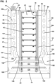
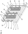
- Frame 10 includes a central zone 40.
- Central zone 40 includes an upper equipment zone 42 and a lower cable tray zone 44.
- slack storage zones 46 On either side of central zone 40 are slack storage zones 46.
- frame 10 includes two slack storage zones 46 which are mirror images of one another.
- Slack storage zone 46 includes cable management fingers 48 in a vertical column dividing the slack storage zone 46 from the central zone 40 in the area of the equipment zone 42. Management fingers support cables exiting horizontally from equipment 12.
- Slack storage zone 46 further includes a first cable channel 80, a second cable channel 82, a third cable channel 84, and a fourth cable channel 86. These channels are generally vertically oriented for handling cables in various manners, as will be described herein.
- the illustrated preferred embodiments include three front trays in the form of a first front tray 60, a second front tray 62, and a third front tray 64.
- three trays are also provided in the form of a first rear tray 70, a second rear tray, and a third rear tray 74. At a minimum, one front tray and one rear tray are useful for cable routing with respect to frame 10 and other frames 10 lined up in a row.
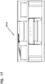
- Frame 10 defines various cable pathways for the patch cables to move within frame 10, to move between frames 10 and to exit from frame 10.
- frame 10 defines three horizontal front cable pathways 102, 104, 106.
- Frame 10 also further defines three rear horizontal pathways 112, 114, 116.
- Frame 10 further defines three front to rear pathways also extending in a horizontal direction.
- the front-to-rear pathways 122, 124, 126 allow for cable communication between the front horizontal pathways 102, 104, 106 and the rear horizontal pathways 112, 114, 116.
- Fig. 7 shows cables or cords A-D as examples.
- Cable A extends from the front to the rear and back to the front.
- Cable B shows how cables exit the frame to go elsewhere in the facility.
- Cable C shows how a cable can go between two frames 10.
- Cable D shows how a cable can pass through the two frames 10 to other frames or locations. Other variations are possible.
- Central zone 40 includes a base 140, two vertical uprights 142, and a top bar 144.
- Vertical uprights 142 are configured for receiving equipment 12, such as with fasteners.
- Slack storage zone 46 includes a slack storage body 148, including a first side 150 spaced from a second side 152 and connected by a back 154.
- Slack storage zone 46 includes a lower divider 160, a first divider 162 and a second divider 164 for defining the various channels 80, 82, 84, 86.
- Various cable management spools and/or radius limiters are utilized in slack storage zone 46 including a lower spool 180, a column of middle spools 182, a second lower spool 184, and an upper radius limiter 5 and lower 186, 188.
- Lower divider 160 encourages a technician to use a proper spool 182 for slack storage.
- Front trays 60, 62, 64 generally all include a base 200, an opening 202, opposite ends 204, 206, and a front flange 208. In the illustrated embodiment, each of the front trays 60, 62, 64 have different lengths. Front trays 60, 62 have rounded ends 204, 206 in a downward direction for cable radius limiter protection. In other embodiments, the front trays 60, 62, 64 can all have the same length (see FIGS. 22-29 ).
- Frame 10 also includes a main front base 220, and a main rear base 222 for engaging the floor of the facility.
- Guides 240 define the front to rear passages 122, 124, 126. Guides 240 are received in openings 202 of front trays 60, 62, 64. Guides 240 include a base 242 with uprights 244 to provide cable radius limiter protection.
- Rear trays 70, 72, 74 all generally include a base 260, a first flange 262, a spaced apart second flange 264 defining a channel, and two ends 266, 268.
- Frame 10 also includes rear mounting strips 280 and a plurality of rear brackets 282, 284 for managing cables on rear 28 of frame 10, such as the incoming and outgoing cables 14.
- Brackets 282 are shown as U-shaped, and brackets 284 are shown as planar shapes.
- the troughs of rear 28 frame 10 generally align to present a continuous trough surface extending between adjacent frames. More than two frames can be provided and allow for cabling to extend between one frame to any other frame in the same row. Front trays 116 also align.
- Patch cables are managed on the front 26 of frame 10 utilizing the slack storage zones 46 and the front trays 60, 62, 64.
- the front to rear pathways 122, 124, 126 allow for patch cables to move between front 26 and rear 28 of frame 10. With such a feature, patch cables can extend between different frames also using rear trays 70, 72, 74.
- a technician can utilize the front trays 60, 62, 64 as desired for managing patch cables within frame 10, or between adjacent frames in a row. Also, the technician can have patch cables 16 exit frame 10 vertically and enter a cable management system, such as fiber trough system positioned above frames 10 and be transported to other areas within the facility, or to another row of frames 10.
- a cable management system such as fiber trough system positioned above frames 10 and be transported to other areas within the facility, or to another row of frames 10.
- One such system is a Fiberguide Trough System by CommScope of Hickory, NC.
- Equipment 12 can be any or a variety of equipment, such as passive or active equipment. In one example embodiment, equipment 12 is a chassis with internal blades including connectivity equipment, such as connectors and adapters. Breakout modules and splitter modules can also be used. Further details pertaining to the bladed chasses can be found in U.S. Publication No. 2018-0224621 and U.S. Patent No. 9709765 .
- FIGS 9A-E show various examples of patch cords 14 and possible pathways for the cords to follow.
- Cord 302 exits the equipment 12 to the left, to trough 60, pathway 102 and then pathway 122 to the rear 28 of frame 10.
- Cord 304 exits the equipment 12 to the right, to trough 62 to pathway 104 and then pathway 124 to the rear 28 of frame 10.
- Cord 306 exits the equipment 12 to the left, to channel 86 and then out of frame 10.
- Cord 308 exits the equipment 12 to the right, to trough 64 to pathway 106 and then horizontally to another frame 10.
- Cords 310, 312 exit the equipment 12 to the left, to trough 62, pathway 104 and then pathway 124 to the rear 28 of frame 10, for management together.
- Cord 314 exits the equipment 12 to the left, to trough 64, pathway 106 and then pathway 126 to the rear 28 of frame 10.
- Cord 316 exits the equipment 12 to the right, to channel 84 to pathway 126 and then horizontally out of frame 10 to another frame.
- Cords 318, 320 exit the equipment 12 to the left, to troughs 60 and 62 respectively, pathways 102 and 104 respectively and then pathways 122 and 124 respectively to the rear 28 of frame 10, for management separately.
- FIG. 14-21 A second embodiment of frame 1010 is shown in Figures 14-21 . Similar functionality and structure is provided as in frame 10.
- a third embodiment of frame 2010 is shown in Figures 22-30 . Similar functionality and structure is provided as in frame 10.
- the front trays 2060, 2062, 2064 all have the same length and align to form complete troughs when more than one frame 2010 is provided in a row.
- the patch cords linking equipment 12 can be managed solely on the front side or with a combination of the front side trays and the rear side trays.
- the trays are located below the equipment.
- the trays are easily accessible for the cables via the cable slack storage systems.
- the equipment zone defines an obstructed space for a variety of sizes of equipment, such as in the vertical direction and in a depth direction. No front or rear troughs interfere with the equipment during assembly of the frame. No rear troughs need to be specially placed behind the equipment. All of the rear troughing is positioned in the cable tray zone away from the equipment zone.
- the technician has a variety of routing options. Such options include side to side, front to back, or out the top of the frame.
- Such a frame is more versatile than one designed for certain equipment with a defined height and depth. In the disclosed frames, a wide variety of equipment heights and depths can be handled without modifications to the frame.
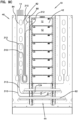
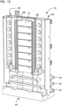
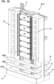
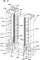
- a fourth embodiment 3010 of a frame is shown in Figures 31-34 . Similar functionality and structure is provided as in frame 10 except that the central zone 3040 of the frame 3010 includes a larger upper equipment zone 3042 and a smaller lower cable tray zone 3044.
- the cable tray zone 3044 include only one front tray 3064 and one rear tray 3074.
- Equipment 3012 are mountable at the upper equipment zone 3042.
- Equipment 3012 has incoming and outgoing cables 3014, as well as patch cables or patch cords which connect different pieces of equipment 3012 to each other, or to other telecommunications equipment.
- the patch cords 3016 typically are managed and connected to equipment 3012 on a front 3026 of frame 3010.
- the incoming and outgoing cables 3014 are typically managed on a rear 3028 of frame 3010.
- the patch cord 3016 also can be managed on the rear 3028 of frame 3010.
- frame 3010 On either side of central zone 3040 are slack storage zones 3046.
- frame 3010 includes two slack storage zones 3046 which are mirror images of one another.
- Slack storage zone 3046 includes cable management fingers 3048 in a vertical column dividing the slack storage zone 3046 from the central zone 3040 in the area of the equipment zone 3042. Management fingers support cables exiting horizontally from equipment 3012.
- Slack storage zone 3046 includes a first cable channel 3080, a second cable channel 3082, a third cable channel 3084, and a fourth cable channel 3086. These channels are generally vertically oriented for handling cables.
- Each slack storage zone 3046 includes a lower divider 3160, a first divider 3162 and a second divider 3164 for defining the various channels 3080, 3082, 3084, 3086.
- Various cable management spools and/or radius limiters are utilized in each slack storage zone 3046 including a lower spool 3180, a column of middle spools 3182, one or more second lower spools 3184, an upper radius limiter 3186, and a lower radius limiter 3188.
- the lower divider 3160 encourages a technician to use a proper spool 3182 for slack storage.
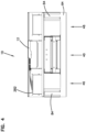
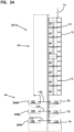
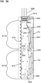
- a splice equipment assembly 3200 can be mounted at the rear 3028 of the frame 3010.
- the splice equipment assembly 3200 can be mounted at the rear 3028 to one side of the central zone 3040. Cables on rear 3028 of frame 3010, such as the incoming and outgoing cables 3014, can be spliced to one or more trunk cables 3008 routed to the frame 3010.
- Frame 3010 also may include one or more rear mounting strips and/or a plurality of rear brackets 3282, 3284 at the rear of the frame 3010 at the opposite side of the central zone 3040.
- Brackets 3282 are shown as U-shaped, and brackets 3284 are shown as planar shapes.
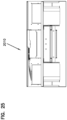
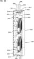
- the splice equipment assembly 3200 includes a body 3202 and a cover 3204.
- the body 3202 defines an interior 3206 accessible through an access aperture 3208.
- the cover 3204 is movable to selectively cover and expose the access aperture 3208.
- the cover 3204 is pivotable relative to the body 3202.
- the cover 3204 is removable from the body 3202 (e.g., by lifting the cover 3204 to free tabs of the cover 3204 from slots defined by the body 3202).
- the body 3202 also defines a trunk cable port arrangement 3210 through which the trunk cables 3008 may extend into the interior 3206 of the splice equipment assembly 3200 and at least one equipment cable port 3212 through which the incoming and outgoing cables 3014 of the equipment 3012 may extend into the interior 3206 of the splice equipment assembly 3200.
- One or more splice trays 3224 are disposed within the interior 3206.
- the trunk cables 3008 are optically coupled to the incoming and outgoing cables 3014 at the splice trays 3224. A user may access the splice trays 3224 through the access aperture 3208.
- the incoming and outgoing cables 3014 include fibers or fiber ribbons disposed within protective sleeving (e.g., mesh sleeves).
- the protective sleeving may have first ends disposed within the equipment 3012 and second ends that are disposed within the splice equipment assembly 3200 when the incoming and outgoing cables 3014 are routed to the splice trays 3224 within the splice equipment assembly 3200.
- the second ends of the protective sleeving may be routed to the respective splice trays 3224.
- the second ends of the protective sleeving may be anchored to the respective splice trays 3224.
- a conduit C may be positioned around the incoming and outgoing cables 3014 between the equipment 3012 and the splice equipment assembly 3200.
- the conduit C includes a corrugated tube (e.g., a plastic tube).
- the conduit C is slit to enable lateral mounting of the conduit C about the cables 3014.
- the conduit C surrounds the protective sleeving disposed about the incoming and outgoing cables 3014. In other examples, the incoming and outgoing cables 3014 within the conduit C do not have protective sleeving.
- the conduit C extends to the equipment cable port 3212. In certain examples, the conduit C extends at least partially through the equipment cable port 3212. In an example, an end of the conduit C is secured at the equipment cable port 3212 (e.g., clamped at a plug received in the equipment cable port 3212). In other examples, the conduit C extends through the equipment cable port 3212 and into an interior 3206 of the splice equipment assembly 3200. In some examples, the conduit C extends from an interior of the equipment 3012. In other examples, the conduit C extends from an exterior of the equipment 3012 adjacent an exit cable port.
- the body 3202 of the splice equipment assembly 3200 includes a rear wall 3230, a first side wall 3232, an opposite second side wall 3234, a bottom wall 3236, and a top wall 3238.
- the access aperture 3208 is generally defined by edges of the first side wall 3232, the second side wall 3234, the bottom wall 3236, and the top wall 3238. Retaining lips 3240 may extend into the access aperture 3208 from the bottom wall 3236 and/or from the top wall 3238.
- the trunk cable port arrangement 3210 is disposed at the top wall 3238. In some examples, the trunk cable port arrangement 3210 includes a single aperture through which multiple trunk cables 3008 may extend. In other examples, the trunk cable port arrangement 3210 includes a plurality of apertures through which respective trunk cables may extend. In some examples, the trunk cable port arrangement 3210 is environmentally sealed. In other examples, the trunk cable port arrangement 3210 may include a non-sealing cover 3214 to inhibit dust or other such contaminants from entering the splice enclosure. In an example, the cover 3214 includes a brush-style element extending across the one or more apertures of the trunk cable port arrangement 3210.
- the trunk cables 3008 may be anchored within the interior 3206 of the splice equipment assembly 3200.
- an anchor block 3260 may be disposed within the splice equipment assembly 3200 (e.g., at the rear wall 3230).
- One or more clamps 3262 are mounted to the anchor block 3260 to hold the trunk cables 3008 to the anchor block 3260.
- the anchor block 3260 is disposed at an upper portion of the splice module interior 3206 adjacent the trunk cable port arrangement 3210.
- the splice equipment assembly 3200 has a height H M that extends along a majority of a height He of the upper equipment zone 3042. In certain implementations, the height H M is substantially the same as the height He of the upper equipment zone 3042. In certain examples, the height H M of the splice equipment assembly 3200 extends along a majority of a height of the frame 3010. In certain examples, the height H M of the splice equipment assembly 3200 is sufficient to enable spacing of the equipment cable ports 3212 along the side of the upper equipment zone 3042 so that incoming and outgoing cables 3014 can extend generally straight between the respective equipment 3012 and a respective equipment cable port 3212 (e.g., see Figure 33 ).
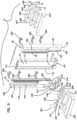
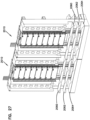
- the splice trays 3224 can be organized into one or more splice tray assemblies 3220.
- Each splice tray assembly 3220 includes one or more splice trays 3224 coupled to a mounting frame 3222.
- the mounting frame 3222 secures to the rear wall 3230.
- the trays 3224 are staggered along the mounting frame 3222 for easier access.
- each tray 3224 may be mounted at a different position along a ramped surface of the frame 3222.
- the splice trays 3224 are removably mounted to the frame 3222 so that one or more of the trays 3224 can be removed from the frame 3222 and moved to a nearby work surface without disconnecting the already spliced cables.
- each splice tray 3224 has a first major side and a second major side.
- the first major side includes splice holders 3226 at which optical splices can be stored.
- a removable cover 3228 can be disposed at the first major side to cover the splice holders (see Figure 37 ).
- Each tray 3224 may be separately movable relative to the frame 3222 between a stowed position and an access position.
- a forward-most tray 3224 is disposed in the access position while the remaining trays 3224 of the splice tray assembly 3220 are disposed in the stowed position.
- the first major side of the tray 3224 is accessible to a technician.
- the first major side faces the rear of the splice equipment assembly 3200 while the second major side faces the access aperture 3208.
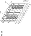
- the splice equipment assembly 3200 includes a cable routing arrangement 3250 that facilitates routing the cables 3008, 3014 from the cable ports 3210, 3212 to the splice trays 3224.
- the cable routing arrangement 3250 includes various routing guides that define at least a first routing path P1 between the trunk cable port arrangement 3210 and at least one splice tray 3224 and a second routing path P2 between an equipment cable port 3212 and the at least one splice tray 3224 (see Figure 38 ).
- the second routing path P2 is configured such that the incoming and outgoing cables 3014 of the equipment 3012 have a common length.
- the incoming and outgoing cables 3014 routed to equipment 3012 mounted at a top of the frame 3222 have common lengths with the incoming and outgoing cables 3014 routed to equipment 3012 mounted at a middle of the frame 3222.
- sufficient slack length of each incoming and outgoing cables 3014 is accommodated along the second routing path P2 to enable the incoming and outgoing cables 3014 to have common lengths.
- the first routing path P1 extends at least partially along the first side wall 3232 and does not extend along the second side wall 3234 while the second routing path P2 extends at least partially along the second side wall 3234 and does not extend along the first side wall 3232.
- the first routing path P1 extends at least partially along the rear wall 3230.
- the second routing path P2 extends at least partially along the rear wall 3230.
- none of the routing paths P1, P2 extend circumferentially around the splice trays 3224.
- the first routing path P1 and the second routing path P2 do not cross or otherwise overlap each other.
- a splice tray 3224 to which fibers are routed can be more easily removed from the splice equipment assembly 3200 without disconnecting the fibers from the splice tray 3224.
- multiple groups 3220 of splice trays 3224 are disposed within the interior 3206 of the splice equipment assembly 3200.
- separate first routing paths lead from the trunk cable port arrangement 3210 to the respective splice tray assemblies 3220 and separate second routing paths lead from certain ones of the equipment ports 3212 to the respective splice tray assemblies 3220.
- the interior 3206 of the splice equipment assembly 3200 includes a plurality of regions, each region has a respective splice tray assembly 3220.
- each region has respective first and second cable routing paths P1, P2 to the splice tray assembly 3220.
- each region has a respective set of equipment cable ports 3212.
- a first region R1 is disposed above a second region R2.
- the splice equipment assembly 3200 may include additional regions.
- the regions are disposed in a vertical column.
- the first routing path P1 is configured such that the trunk cables 3008 have a common length.
- the trunk cables 3008 routed to the splice tray assembly 3220 at the first region R1 have a common length with the trunk cables 3008 routed to the splice tray assembly 3220 at the second region R2.
- sufficient slack length of each trunk cables 3008 is accommodated along the first routing path P1 to enable the trunk cables 3008 to have common lengths.
- one first routing path P1a extends from the trunk cable port arrangement 3210 towards a first splice tray assembly 3220a ( Figure 35 ) in the first region R1 and another first routing path P1b extends from the trunk cable port arrangement 3210 towards a second splice tray assembly 3220b ( Figure 35 ) in the second region R2.
- One second routing path P2a extends from an equipment cable port 3212 towards the first splice tray assembly 3220a in the first region R1 and another second routing path P2b extends from another equipment cable port 3212 towards the second splice tray assembly 3220b in the second region R2.
- the splice tray splice tray assemblies 3220 are disposed within the interior 3206 so that for each first routing path P1, a majority of the path does not overlap with the other first routing paths P1. In certain implementations, the splice tray assemblies 3220 are disposed within the interior 3206 so that for each second routing path P2, a majority of the path does not overlap with the other second routing paths P2. In certain examples, the first splice tray assembly 3220a is disposed above the second splice tray assembly 3220b. In such examples, one set of first and second cable routing paths P1a, P2a may be disposed above a majority of another set of first and second cable routing paths P1b, P2b.
- one of the second routing paths P2a is provided for fibers extending from any of a first set 3212a ( Figure 39 ) of the equipment cable ports 3212 and another of the second cable routing paths P2b is provided for fibers extending from any of a second set 3212b ( Figure 39 ) of the equipment cable ports 3212.
- the cable routing arrangement 3250 includes a combination of bend radius limiters 3252, 3256 and cable clips 3254.
- various bend radius limiters 3252, 3256 may be disposed at upper and/or lower portions of the cable routing paths P1, P2 to create multiple loops or layers within the path.
- the cable clips 3254 manage the fibers along the paths P1, P2.
- an example first cable routing path P1a extends from the trunk cable port arrangement 3210 and at least partially down the rear wall 3230.
- the first cable routing path P1 loops back up an inner surface of the first side wall 3232 towards the rear, loops over a bend radius limiter 3252, and extends back down the inner surface of the first side wall 3232.
- the first cable routing path P1 extends from the first side wall 3232, around a spool 3256 or other bend radius limiter and up towards a splice tray 3224.
- Cable clips 3254 may be disposed at the rear wall 3230 and the inner surface of the first side wall 3232 to hold the fibers at the respective walls.
- a half spool 3252 or other bend radius limiter may be disposed at the real wall 3230 above the first splice tray assembly 3220 of splice trays 3224 to guide the fibers from the trunk cable to a side of the splice trays 3224.
- the spool 3256 is sufficiently deep to facilitate routing the trunk cable fibers to any of the splice trays 3224 in the splice tray assembly 3220.
- an example second cable routing path P2a extends from the equipment cable ports 3212, up an inner surface of the second side wall 3234, over a half-spool 3252 or other bend radius limiter, down the inner surface of the second side wall 3234, around a spool 3256 or other bend radius limiter, and up to the splice trays 3224.
- additional half-spools 3252 or other bend radius limiters may be disposed at the inner surface of the second side wall 3234 to separate the fibers routed up the second side wall 3234 and the fibers routed down the second side wall 3234.
- the additional radius limiters also may guide the equipment cable fibers from the equipment cable ports 3212 to the upward section of the path towards the rear side of the second side wall 3234.
- optical splicing between the equipment cable fibers and the trunk cable fibers is performed while the splice tray 3224 is mounted to the frame 3222 within the splice equipment assembly 3200.
- the desired splice tray 3224 can be pivoted or otherwise moved to the access position, the cover 3228 can be removed, and the optical splices can be mounted to the tray 3224.
- the splice tray 3224 is removed from the splice equipment assembly 3200 to optically splice the equipment cable fibers and the trunk cable fibers.
- the fibers routed to the splice tray 3224 can be unhooked from the radius limiter 3256 to enable the splice tray 3224 to be removed from the frame 3222 and moved to a work station external of the splice equipment assembly 3200.
Landscapes
- Physics & Mathematics (AREA)
- General Physics & Mathematics (AREA)
- Optics & Photonics (AREA)
- Engineering & Computer Science (AREA)
- Computer Networks & Wireless Communication (AREA)
- Light Guides In General And Applications Therefor (AREA)
- Structure Of Telephone Exchanges (AREA)
- Details Of Indoor Wiring (AREA)
Claims (15)
- Spleißausrüstungsanordnung (3200), umfassend:ein Gehäuse (3202) mit einer Höhe, die sich zwischen einer Oberseite (3238) und einer Unterseite (3236) erstreckt, einer Breite, die sich zwischen einer ersten Seite (3232) und einer zweiten Seite (3234) erstreckt, und einer Tiefe, die sich zwischen einer Rückseite (3230) und einer offenen Vorderseite, die Zugang zu einem Innenraum (3206) des Gehäuses (3202) bereitstellt, erstreckt;einen Hauptkabeldurchlass (3210), der an der Oberseite des Gehäuses (3202) angeordnet ist, um Zugang zu dem Innenraum (3206) des Gehäuses (3202) bereitzustellen;zumindest einen Ausrüstungskabeldurchlass (3212), der an der zweiten Seite des Gehäuses (3202) angeordnet ist, um Zugang zu dem Innenraum (3206) des Gehäuses (3202) bereitzustellen;eine Spleißfachanordnung (3220), die innerhalb des Gehäuses (3202) angeordnet ist, wobei die Spleißfachanordnung (3220) einen Rahmen (3222) beinhaltet, der zumindest ein Spleißfach (3224) hält;eine erste Führungselementvorrichtung (3250), die an einer Innenfläche an der ersten Seite des Gehäuses (3202) angeordnet ist, um einen ersten Kabelführungsweg (P1) zwischen dem Hauptkabeldurchlass (3210) und der Spleißfachanordnung (3220) zu definieren; undeine zweite Führungselementvorrichtung (3250), die an einer Innenfläche an der zweiten Seite des Gehäuses (3202) angeordnet ist, um einen zweiten Kabelführungsweg (P2) zwischen dem zumindest einen Ausrüstungskabeldurchlass (3212) und der Spleißfachanordnung (3220) zu definieren, wobei sich der zweite Kabelführungsweg (P2) nicht mit dem ersten Kabelführungsweg (P1) überschneidet.
- Spleißausrüstungsanordnung (3200) nach Anspruch 1, wobei die Spleißfachanordnung (3220) an der Rückseite (3230) des Gehäuses (3202) angebracht ist.
- Spleißausrüstungsanordnung (3200) nach Anspruch 1, wobei die Spleißfachanordnung (3220) eine Vielzahl von Spleißfächern (3224) beinhaltet, die an dem Rahmen (3222) angebracht sind, wobei jedes Spleißfach (3224) zwischen einer Verstauposition und einer Zugangsposition bewegbar ist.
- Spleißausrüstungsanordnung (3200) nach einem der Ansprüche 1-3, wobei der Innenraum (3206) des Gehäuses (3202) einen ersten Bereich (R1) und einen zweiten Bereich (R2) beinhaltet, wobei die Spleißfachanordnung (3220) eine erste Spleißfachanordnung (3220, 3220a) ist, die in dem ersten Bereich (R1) angeordnet ist, und wobei eine zweite Spleißfachanordnung (3220, 3220b) innerhalb des Gehäuses (3202) in dem zweiten Bereich (R2) angebracht ist, und wobei der erste und der zweite Kabelführungsweg (P1, P1a, P2, P2a) den ersten Bereich (R1) bedienen, und wobei ein zusätzlicher erster und zweiter Kabelführungsweg (P1, P1b, P2, P2b) den zweiten Bereich (R2) bedienen.
- Spleißausrüstungsanordnung (3200) nach einem der Ansprüche 1-4, wobei sich der erste Kabelführungsweg (P1, P1a, P1b) entlang der ersten Seite (3232) und der Rückseite (3230) des Gehäuses (3202) erstreckt und wobei sich der zweite Kabelführungsweg (P2, P2a, P2b) entlang der zweiten Seite (3234) und der Rückseite (3230) des Gehäuses (3202) erstreckt.
- Spleißausrüstungsanordnung (3200) nach einem der Ansprüche 1-5, wobei sich weder der erste Kabelführungsweg (P1, P1a, P1b) noch der zweite Kabelführungsweg (P2, P2a, P2b) in Umfangsrichtung um die Spleißfachanordnung (3220) herum erstreckt.
- Spleißausrüstungsanordnung (3200) nach einem der Ansprüche 1-6, wobei der zumindest eine Ausrüstungskabeldurchlass (3212) einer einer Vielzahl von Ausrüstungskabeldurchlässen (3212) ist, die sich durch die zweite Seite (3234) hindurch erstrecken.
- Spleißausrüstungsanordnung (3200) nach Anspruch 7, wobei die Ausrüstungskabeldurchlässe (3212) in einer vertikalen Säule angeordnet sind.
- Spleißausrüstungsanordnung (3200) nach Anspruch 7, wobei die Ausrüstungskabeldurchlässe (3212) entlang eines Großteils einer Höhe der zweiten Seite (3234) beabstandet sind.
- Telekommunikationsausrüstungsrahmen (3010), der die Spleißausrüstungsanordnung (3200) nach einem der vorhergehenden Ansprüche umfasst.
- Telekommunikationsausrüstungsrahmen (3010) nach Anspruch 10, ferner umfassend:eine Basis (140) und zwei vertikal aufrechte Elemente (142) und ein oberes Element (144), das eine zentrale Zone (3040) definiert;wobei die aufrechten Elemente (142) ferner eine obere Ausrüstungszone (3042) definieren;wobei die aufrechten Elemente (142) ferner eine untere Kabelfachzone (3044) definieren;ein oder mehrere vordere Fächer (3064) in der Kabelfachzone (3044) und Öffnungen durch den Rahmen (3010) zu einem oder mehreren hinteren Fächern (3074);wobei die durch die zwei aufrechten Elemente (142) definierte Ausrüstungszone (3042) ohne Kabelmanagementstruktur zum Empfangen von Telekommunikationsausrüstung offen ist;zumindest eine an die zentrale Zone (3040) angrenzende Lagerzone für überschüssiges Kabel (3046), die eine Vielzahl von Kabelmanagementvorrichtungen (3180, 3182, 3184, 3186, 3188) zum Lagern von überschüssigem Kabel beinhaltet, wobei die Spleißausrüstungsanordnung (3200) gegenüber der zumindest einen Lagerzone für überschüssiges Kabel (3046) angeordnet ist.
- Telekommunikationsausrüstungsrahmen nach Anspruch 11, ferner umfassend eine zweite Lagerzone für überschüssiges Kabel (3046) auf einer gegenüberliegenden Seite der zentralen Zone (3040) relativ zu der ersten Lagerzone für überschüssiges Kabel (3046).
- Telekommunikationsausrüstungsrahmen nach einem der Ansprüche 11 und 12, wobei die vorderen Fächer (3064) unterschiedliche Längen aufweisen.
- Telekommunikationsausrüstungsrahmen nach einem der Ansprüche 11-12, wobei das eine oder die mehreren vorderen Fächer (3064) nur ein einziges vorderes Fach (3064) beinhalten.
- Telekommunikationsausrüstungsrahmen nach einem der Ansprüche 11-12, wobei das eine oder die mehreren hinteren Fächer (3074) nur ein einziges hinteres Fach (3074) beinhalten.
Applications Claiming Priority (4)
| Application Number | Priority Date | Filing Date | Title |
|---|---|---|---|
| US201862720057P | 2018-08-20 | 2018-08-20 | |
| US201862720784P | 2018-08-21 | 2018-08-21 | |
| US201962803961P | 2019-02-11 | 2019-02-11 | |
| PCT/US2019/047182 WO2020041255A1 (en) | 2018-08-20 | 2019-08-20 | Telecommunications equipment frame |
Publications (3)
| Publication Number | Publication Date |
|---|---|
| EP3841853A1 EP3841853A1 (de) | 2021-06-30 |
| EP3841853A4 EP3841853A4 (de) | 2022-05-18 |
| EP3841853B1 true EP3841853B1 (de) | 2024-01-10 |
Family
ID=69591174
Family Applications (1)
| Application Number | Title | Priority Date | Filing Date |
|---|---|---|---|
| EP19852770.7A Active EP3841853B1 (de) | 2018-08-20 | 2019-08-20 | Rahmen für telekommunikationsausrüstung |
Country Status (4)
| Country | Link |
|---|---|
| US (2) | US12169318B2 (de) |
| EP (1) | EP3841853B1 (de) |
| MX (1) | MX2021001974A (de) |
| WO (1) | WO2020041255A1 (de) |
Families Citing this family (4)
| Publication number | Priority date | Publication date | Assignee | Title |
|---|---|---|---|---|
| EP3841853B1 (de) | 2018-08-20 | 2024-01-10 | CommScope Technologies LLC | Rahmen für telekommunikationsausrüstung |
| US12468105B2 (en) | 2019-02-11 | 2025-11-11 | Commscope Technologies Llc | Splice closure |
| CN113395858B (zh) * | 2021-06-22 | 2022-07-01 | 中国核动力研究设计院 | 一种布线结构 |
| DE102022109405A1 (de) * | 2022-04-19 | 2023-10-19 | Kaiser Gmbh & Co. Kg | Netzverteilerschrank |
Family Cites Families (22)
| Publication number | Priority date | Publication date | Assignee | Title |
|---|---|---|---|---|
| US4266853A (en) | 1979-03-12 | 1981-05-12 | Northern Telecom Limited | Device for organizing optical fibers and the like |
| US4995688A (en) | 1989-07-31 | 1991-02-26 | Adc Telecommunications, Inc. | Optical fiber distribution frame |
| US6535682B1 (en) * | 1999-03-01 | 2003-03-18 | Adc Telecommunications, Inc. | Optical fiber distribution frame with connector modules |
| US6760531B1 (en) * | 1999-03-01 | 2004-07-06 | Adc Telecommunications, Inc. | Optical fiber distribution frame with outside plant enclosure |
| US7116777B2 (en) | 2002-04-05 | 2006-10-03 | Adc Telecommunications, Inc. | Termination frame with modules and method |
| US7142764B2 (en) * | 2003-03-20 | 2006-11-28 | Tyco Electronics Corporation | Optical fiber interconnect cabinets, termination modules and fiber connectivity management for the same |
| US6792191B1 (en) | 2003-04-22 | 2004-09-14 | Corning Cable Systems Llc | Local convergence cabinet |
| US7397996B2 (en) | 2005-08-02 | 2008-07-08 | Adc Telecommunications, Inc. | Cable management panel with rear entry |
| US7330626B2 (en) | 2005-08-31 | 2008-02-12 | Adc Telecommunications, Inc. | Cabinet including optical bulkhead plate for blown fiber system |
| US7816602B2 (en) | 2006-02-13 | 2010-10-19 | Adc Telecommunications, Inc. | Fiber distribution hub with outside accessible grounding terminals |
| US7711234B2 (en) * | 2006-10-02 | 2010-05-04 | Adc Telecommunications, Inc. | Reskinnable fiber distribution hub |
| US7751672B2 (en) | 2007-10-31 | 2010-07-06 | Adc Telecommunications, Inc. | Low profile fiber distribution hub |
| WO2009089327A2 (en) | 2008-01-09 | 2009-07-16 | Adc Telecommunications, Inc. | Wall box adapted to be mounted at a mid-span access location of a telecommunications cable |
| EP2335461B9 (de) | 2008-09-05 | 2016-07-13 | Tyco Electronics Services GmbH | Rahmen mit kabelführung |
| WO2013092251A1 (en) | 2011-12-22 | 2013-06-27 | Tyco Electronics Raychem Bvba | Isolated splice region with removable wall |
| WO2015055586A1 (en) | 2013-10-18 | 2015-04-23 | Tyco Electronics Raychem Bvba | Mounting system for telecommunications distribution elements |
| ES2894250T3 (es) * | 2014-04-14 | 2022-02-14 | Commscope Connectivity Belgica Bvba | Recinto de fibra óptica con cajón de gestión de cables |
| SG11201610605PA (en) | 2014-06-23 | 2017-01-27 | Adc Telecommunications Inc | Bladed chassis systems |
| WO2017019910A1 (en) | 2015-07-29 | 2017-02-02 | Commscope Technologies Llc | Bladed chassis systems |
| US10502914B2 (en) | 2017-03-28 | 2019-12-10 | Ofs Fitel, Llc | Stackable telecommunication cabinet construction |
| EP3841853B1 (de) | 2018-08-20 | 2024-01-10 | CommScope Technologies LLC | Rahmen für telekommunikationsausrüstung |
| US12468105B2 (en) | 2019-02-11 | 2025-11-11 | Commscope Technologies Llc | Splice closure |
-
2019
- 2019-08-20 EP EP19852770.7A patent/EP3841853B1/de active Active
- 2019-08-20 WO PCT/US2019/047182 patent/WO2020041255A1/en not_active Ceased
- 2019-08-20 MX MX2021001974A patent/MX2021001974A/es unknown
- 2019-08-20 US US17/269,656 patent/US12169318B2/en active Active
-
2024
- 2024-11-27 US US18/963,064 patent/US20250130385A1/en active Pending
Also Published As
| Publication number | Publication date |
|---|---|
| US20250130385A1 (en) | 2025-04-24 |
| US12169318B2 (en) | 2024-12-17 |
| EP3841853A4 (de) | 2022-05-18 |
| WO2020041255A1 (en) | 2020-02-27 |
| EP3841853A1 (de) | 2021-06-30 |
| MX2021001974A (es) | 2021-04-28 |
| US20210173165A1 (en) | 2021-06-10 |
Similar Documents
| Publication | Publication Date | Title |
|---|---|---|
| US20250130385A1 (en) | Telecommunications equipment frame | |
| EP2241915B1 (de) | Optischer Verteilerschrank mit Modulen mit schwenkbaren Rahmen für Glasfaserstecker | |
| AU772317B2 (en) | Optical fiber distribution frame with pivoting connector panels | |
| US9810868B2 (en) | Optical fiber distribution frame with outside plant enclosure | |
| US20260043980A1 (en) | Splice closure | |
| EP3523687B1 (de) | Telekommunikationssystem und -verfahren | |
| US11536920B2 (en) | Fiber optic telecommunications tray with enhanced accessibility and management | |
| EP3752875B1 (de) | An einem gestell montierbares glasfaserspleissgehäuse | |
| WO2022035966A1 (en) | Optical fiber organizer with improved fiber routing customizability for a telecommunications closure | |
| US20210185416A1 (en) | Telecommunications equipment cabinet | |
| ZA200107375B (en) | Optical fiber distribution frame with pivoting connector panels. | |
| HK1042949B (en) | Optical fiber distribution frame with pivoting connector panels |
Legal Events
| Date | Code | Title | Description |
|---|---|---|---|
| STAA | Information on the status of an ep patent application or granted ep patent |
Free format text: STATUS: THE INTERNATIONAL PUBLICATION HAS BEEN MADE |
|
| PUAI | Public reference made under article 153(3) epc to a published international application that has entered the european phase |
Free format text: ORIGINAL CODE: 0009012 |
|
| STAA | Information on the status of an ep patent application or granted ep patent |
Free format text: STATUS: REQUEST FOR EXAMINATION WAS MADE |
|
| 17P | Request for examination filed |
Effective date: 20210211 |
|
| AK | Designated contracting states |
Kind code of ref document: A1 Designated state(s): AL AT BE BG CH CY CZ DE DK EE ES FI FR GB GR HR HU IE IS IT LI LT LU LV MC MK MT NL NO PL PT RO RS SE SI SK SM TR |
|
| DAV | Request for validation of the european patent (deleted) | ||
| DAX | Request for extension of the european patent (deleted) | ||
| A4 | Supplementary search report drawn up and despatched |
Effective date: 20220419 |
|
| RIC1 | Information provided on ipc code assigned before grant |
Ipc: G02B 6/44 20060101ALI20220411BHEP Ipc: H05K 7/14 20060101ALI20220411BHEP Ipc: H05K 7/18 20060101AFI20220411BHEP |
|
| GRAP | Despatch of communication of intention to grant a patent |
Free format text: ORIGINAL CODE: EPIDOSNIGR1 |
|
| STAA | Information on the status of an ep patent application or granted ep patent |
Free format text: STATUS: GRANT OF PATENT IS INTENDED |
|
| INTG | Intention to grant announced |
Effective date: 20230222 |
|
| GRAJ | Information related to disapproval of communication of intention to grant by the applicant or resumption of examination proceedings by the epo deleted |
Free format text: ORIGINAL CODE: EPIDOSDIGR1 |
|
| STAA | Information on the status of an ep patent application or granted ep patent |
Free format text: STATUS: REQUEST FOR EXAMINATION WAS MADE |
|
| GRAP | Despatch of communication of intention to grant a patent |
Free format text: ORIGINAL CODE: EPIDOSNIGR1 |
|
| STAA | Information on the status of an ep patent application or granted ep patent |
Free format text: STATUS: GRANT OF PATENT IS INTENDED |
|
| INTC | Intention to grant announced (deleted) | ||
| INTG | Intention to grant announced |
Effective date: 20230731 |
|
| GRAS | Grant fee paid |
Free format text: ORIGINAL CODE: EPIDOSNIGR3 |
|
| GRAA | (expected) grant |
Free format text: ORIGINAL CODE: 0009210 |
|
| STAA | Information on the status of an ep patent application or granted ep patent |
Free format text: STATUS: THE PATENT HAS BEEN GRANTED |
|
| AK | Designated contracting states |
Kind code of ref document: B1 Designated state(s): AL AT BE BG CH CY CZ DE DK EE ES FI FR GB GR HR HU IE IS IT LI LT LU LV MC MK MT NL NO PL PT RO RS SE SI SK SM TR |
|
| REG | Reference to a national code |
Ref country code: GB Ref legal event code: FG4D |
|
| REG | Reference to a national code |
Ref country code: CH Ref legal event code: EP |
|
| REG | Reference to a national code |
Ref country code: DE Ref legal event code: R096 Ref document number: 602019045022 Country of ref document: DE |
|
| REG | Reference to a national code |
Ref country code: IE Ref legal event code: FG4D |
|
| REG | Reference to a national code |
Ref country code: LT Ref legal event code: MG9D |
|
| REG | Reference to a national code |
Ref country code: NL Ref legal event code: MP Effective date: 20240110 |
|
| REG | Reference to a national code |
Ref country code: AT Ref legal event code: MK05 Ref document number: 1649887 Country of ref document: AT Kind code of ref document: T Effective date: 20240110 |
|
| PG25 | Lapsed in a contracting state [announced via postgrant information from national office to epo] |
Ref country code: NL Free format text: LAPSE BECAUSE OF FAILURE TO SUBMIT A TRANSLATION OF THE DESCRIPTION OR TO PAY THE FEE WITHIN THE PRESCRIBED TIME-LIMIT Effective date: 20240110 |
|
| PG25 | Lapsed in a contracting state [announced via postgrant information from national office to epo] |
Ref country code: NL Free format text: LAPSE BECAUSE OF FAILURE TO SUBMIT A TRANSLATION OF THE DESCRIPTION OR TO PAY THE FEE WITHIN THE PRESCRIBED TIME-LIMIT Effective date: 20240110 |
|
| PG25 | Lapsed in a contracting state [announced via postgrant information from national office to epo] |
Ref country code: IS Free format text: LAPSE BECAUSE OF FAILURE TO SUBMIT A TRANSLATION OF THE DESCRIPTION OR TO PAY THE FEE WITHIN THE PRESCRIBED TIME-LIMIT Effective date: 20240510 |
|
| PG25 | Lapsed in a contracting state [announced via postgrant information from national office to epo] |
Ref country code: LT Free format text: LAPSE BECAUSE OF FAILURE TO SUBMIT A TRANSLATION OF THE DESCRIPTION OR TO PAY THE FEE WITHIN THE PRESCRIBED TIME-LIMIT Effective date: 20240110 |
|
| PG25 | Lapsed in a contracting state [announced via postgrant information from national office to epo] |
Ref country code: GR Free format text: LAPSE BECAUSE OF FAILURE TO SUBMIT A TRANSLATION OF THE DESCRIPTION OR TO PAY THE FEE WITHIN THE PRESCRIBED TIME-LIMIT Effective date: 20240411 |
|
| PG25 | Lapsed in a contracting state [announced via postgrant information from national office to epo] |
Ref country code: HR Free format text: LAPSE BECAUSE OF FAILURE TO SUBMIT A TRANSLATION OF THE DESCRIPTION OR TO PAY THE FEE WITHIN THE PRESCRIBED TIME-LIMIT Effective date: 20240110 Ref country code: RS Free format text: LAPSE BECAUSE OF FAILURE TO SUBMIT A TRANSLATION OF THE DESCRIPTION OR TO PAY THE FEE WITHIN THE PRESCRIBED TIME-LIMIT Effective date: 20240410 |
|
| PG25 | Lapsed in a contracting state [announced via postgrant information from national office to epo] |
Ref country code: ES Free format text: LAPSE BECAUSE OF FAILURE TO SUBMIT A TRANSLATION OF THE DESCRIPTION OR TO PAY THE FEE WITHIN THE PRESCRIBED TIME-LIMIT Effective date: 20240110 |
|
| PG25 | Lapsed in a contracting state [announced via postgrant information from national office to epo] |
Ref country code: AT Free format text: LAPSE BECAUSE OF FAILURE TO SUBMIT A TRANSLATION OF THE DESCRIPTION OR TO PAY THE FEE WITHIN THE PRESCRIBED TIME-LIMIT Effective date: 20240110 |
|
| PG25 | Lapsed in a contracting state [announced via postgrant information from national office to epo] |
Ref country code: RS Free format text: LAPSE BECAUSE OF FAILURE TO SUBMIT A TRANSLATION OF THE DESCRIPTION OR TO PAY THE FEE WITHIN THE PRESCRIBED TIME-LIMIT Effective date: 20240410 Ref country code: NO Free format text: LAPSE BECAUSE OF FAILURE TO SUBMIT A TRANSLATION OF THE DESCRIPTION OR TO PAY THE FEE WITHIN THE PRESCRIBED TIME-LIMIT Effective date: 20240410 Ref country code: LT Free format text: LAPSE BECAUSE OF FAILURE TO SUBMIT A TRANSLATION OF THE DESCRIPTION OR TO PAY THE FEE WITHIN THE PRESCRIBED TIME-LIMIT Effective date: 20240110 Ref country code: IS Free format text: LAPSE BECAUSE OF FAILURE TO SUBMIT A TRANSLATION OF THE DESCRIPTION OR TO PAY THE FEE WITHIN THE PRESCRIBED TIME-LIMIT Effective date: 20240510 Ref country code: HR Free format text: LAPSE BECAUSE OF FAILURE TO SUBMIT A TRANSLATION OF THE DESCRIPTION OR TO PAY THE FEE WITHIN THE PRESCRIBED TIME-LIMIT Effective date: 20240110 Ref country code: GR Free format text: LAPSE BECAUSE OF FAILURE TO SUBMIT A TRANSLATION OF THE DESCRIPTION OR TO PAY THE FEE WITHIN THE PRESCRIBED TIME-LIMIT Effective date: 20240411 Ref country code: ES Free format text: LAPSE BECAUSE OF FAILURE TO SUBMIT A TRANSLATION OF THE DESCRIPTION OR TO PAY THE FEE WITHIN THE PRESCRIBED TIME-LIMIT Effective date: 20240110 Ref country code: BG Free format text: LAPSE BECAUSE OF FAILURE TO SUBMIT A TRANSLATION OF THE DESCRIPTION OR TO PAY THE FEE WITHIN THE PRESCRIBED TIME-LIMIT Effective date: 20240110 Ref country code: AT Free format text: LAPSE BECAUSE OF FAILURE TO SUBMIT A TRANSLATION OF THE DESCRIPTION OR TO PAY THE FEE WITHIN THE PRESCRIBED TIME-LIMIT Effective date: 20240110 |
|
| PG25 | Lapsed in a contracting state [announced via postgrant information from national office to epo] |
Ref country code: PT Free format text: LAPSE BECAUSE OF FAILURE TO SUBMIT A TRANSLATION OF THE DESCRIPTION OR TO PAY THE FEE WITHIN THE PRESCRIBED TIME-LIMIT Effective date: 20240510 Ref country code: PL Free format text: LAPSE BECAUSE OF FAILURE TO SUBMIT A TRANSLATION OF THE DESCRIPTION OR TO PAY THE FEE WITHIN THE PRESCRIBED TIME-LIMIT Effective date: 20240110 |
|
| PG25 | Lapsed in a contracting state [announced via postgrant information from national office to epo] |
Ref country code: SE Free format text: LAPSE BECAUSE OF FAILURE TO SUBMIT A TRANSLATION OF THE DESCRIPTION OR TO PAY THE FEE WITHIN THE PRESCRIBED TIME-LIMIT Effective date: 20240110 Ref country code: PT Free format text: LAPSE BECAUSE OF FAILURE TO SUBMIT A TRANSLATION OF THE DESCRIPTION OR TO PAY THE FEE WITHIN THE PRESCRIBED TIME-LIMIT Effective date: 20240510 Ref country code: PL Free format text: LAPSE BECAUSE OF FAILURE TO SUBMIT A TRANSLATION OF THE DESCRIPTION OR TO PAY THE FEE WITHIN THE PRESCRIBED TIME-LIMIT Effective date: 20240110 Ref country code: LV Free format text: LAPSE BECAUSE OF FAILURE TO SUBMIT A TRANSLATION OF THE DESCRIPTION OR TO PAY THE FEE WITHIN THE PRESCRIBED TIME-LIMIT Effective date: 20240110 |
|
| PG25 | Lapsed in a contracting state [announced via postgrant information from national office to epo] |
Ref country code: DK Free format text: LAPSE BECAUSE OF FAILURE TO SUBMIT A TRANSLATION OF THE DESCRIPTION OR TO PAY THE FEE WITHIN THE PRESCRIBED TIME-LIMIT Effective date: 20240110 |
|
| REG | Reference to a national code |
Ref country code: DE Ref legal event code: R097 Ref document number: 602019045022 Country of ref document: DE |
|
| PG25 | Lapsed in a contracting state [announced via postgrant information from national office to epo] |
Ref country code: SM Free format text: LAPSE BECAUSE OF FAILURE TO SUBMIT A TRANSLATION OF THE DESCRIPTION OR TO PAY THE FEE WITHIN THE PRESCRIBED TIME-LIMIT Effective date: 20240110 |
|
| PG25 | Lapsed in a contracting state [announced via postgrant information from national office to epo] |
Ref country code: CZ Free format text: LAPSE BECAUSE OF FAILURE TO SUBMIT A TRANSLATION OF THE DESCRIPTION OR TO PAY THE FEE WITHIN THE PRESCRIBED TIME-LIMIT Effective date: 20240110 Ref country code: EE Free format text: LAPSE BECAUSE OF FAILURE TO SUBMIT A TRANSLATION OF THE DESCRIPTION OR TO PAY THE FEE WITHIN THE PRESCRIBED TIME-LIMIT Effective date: 20240110 |
|
| PG25 | Lapsed in a contracting state [announced via postgrant information from national office to epo] |
Ref country code: SK Free format text: LAPSE BECAUSE OF FAILURE TO SUBMIT A TRANSLATION OF THE DESCRIPTION OR TO PAY THE FEE WITHIN THE PRESCRIBED TIME-LIMIT Effective date: 20240110 |
|
| PG25 | Lapsed in a contracting state [announced via postgrant information from national office to epo] |
Ref country code: SM Free format text: LAPSE BECAUSE OF FAILURE TO SUBMIT A TRANSLATION OF THE DESCRIPTION OR TO PAY THE FEE WITHIN THE PRESCRIBED TIME-LIMIT Effective date: 20240110 Ref country code: SK Free format text: LAPSE BECAUSE OF FAILURE TO SUBMIT A TRANSLATION OF THE DESCRIPTION OR TO PAY THE FEE WITHIN THE PRESCRIBED TIME-LIMIT Effective date: 20240110 Ref country code: RO Free format text: LAPSE BECAUSE OF FAILURE TO SUBMIT A TRANSLATION OF THE DESCRIPTION OR TO PAY THE FEE WITHIN THE PRESCRIBED TIME-LIMIT Effective date: 20240110 Ref country code: EE Free format text: LAPSE BECAUSE OF FAILURE TO SUBMIT A TRANSLATION OF THE DESCRIPTION OR TO PAY THE FEE WITHIN THE PRESCRIBED TIME-LIMIT Effective date: 20240110 Ref country code: DK Free format text: LAPSE BECAUSE OF FAILURE TO SUBMIT A TRANSLATION OF THE DESCRIPTION OR TO PAY THE FEE WITHIN THE PRESCRIBED TIME-LIMIT Effective date: 20240110 Ref country code: CZ Free format text: LAPSE BECAUSE OF FAILURE TO SUBMIT A TRANSLATION OF THE DESCRIPTION OR TO PAY THE FEE WITHIN THE PRESCRIBED TIME-LIMIT Effective date: 20240110 |
|
| PLBE | No opposition filed within time limit |
Free format text: ORIGINAL CODE: 0009261 |
|
| STAA | Information on the status of an ep patent application or granted ep patent |
Free format text: STATUS: NO OPPOSITION FILED WITHIN TIME LIMIT |
|
| PG25 | Lapsed in a contracting state [announced via postgrant information from national office to epo] |
Ref country code: IT Free format text: LAPSE BECAUSE OF FAILURE TO SUBMIT A TRANSLATION OF THE DESCRIPTION OR TO PAY THE FEE WITHIN THE PRESCRIBED TIME-LIMIT Effective date: 20240110 |
|
| 26N | No opposition filed |
Effective date: 20241011 |
|
| PG25 | Lapsed in a contracting state [announced via postgrant information from national office to epo] |
Ref country code: IT Free format text: LAPSE BECAUSE OF FAILURE TO SUBMIT A TRANSLATION OF THE DESCRIPTION OR TO PAY THE FEE WITHIN THE PRESCRIBED TIME-LIMIT Effective date: 20240110 |
|
| REG | Reference to a national code |
Ref country code: DE Ref legal event code: R119 Ref document number: 602019045022 Country of ref document: DE |
|
| REG | Reference to a national code |
Ref country code: CH Ref legal event code: PL |
|
| PG25 | Lapsed in a contracting state [announced via postgrant information from national office to epo] |
Ref country code: LU Free format text: LAPSE BECAUSE OF NON-PAYMENT OF DUE FEES Effective date: 20240820 |
|
| GBPC | Gb: european patent ceased through non-payment of renewal fee |
Effective date: 20240820 |
|
| PG25 | Lapsed in a contracting state [announced via postgrant information from national office to epo] |
Ref country code: SI Free format text: LAPSE BECAUSE OF FAILURE TO SUBMIT A TRANSLATION OF THE DESCRIPTION OR TO PAY THE FEE WITHIN THE PRESCRIBED TIME-LIMIT Effective date: 20240110 Ref country code: MC Free format text: LAPSE BECAUSE OF FAILURE TO SUBMIT A TRANSLATION OF THE DESCRIPTION OR TO PAY THE FEE WITHIN THE PRESCRIBED TIME-LIMIT Effective date: 20240110 Ref country code: CH Free format text: LAPSE BECAUSE OF NON-PAYMENT OF DUE FEES Effective date: 20240831 |
|
| REG | Reference to a national code |
Ref country code: BE Ref legal event code: MM Effective date: 20240831 |
|
| PG25 | Lapsed in a contracting state [announced via postgrant information from national office to epo] |
Ref country code: DE Free format text: LAPSE BECAUSE OF NON-PAYMENT OF DUE FEES Effective date: 20250301 |
|
| PG25 | Lapsed in a contracting state [announced via postgrant information from national office to epo] |
Ref country code: GB Free format text: LAPSE BECAUSE OF NON-PAYMENT OF DUE FEES Effective date: 20240820 |
|
| PG25 | Lapsed in a contracting state [announced via postgrant information from national office to epo] |
Ref country code: BE Free format text: LAPSE BECAUSE OF NON-PAYMENT OF DUE FEES Effective date: 20240831 |
|
| PG25 | Lapsed in a contracting state [announced via postgrant information from national office to epo] |
Ref country code: FR Free format text: LAPSE BECAUSE OF NON-PAYMENT OF DUE FEES Effective date: 20240831 |
|
| PG25 | Lapsed in a contracting state [announced via postgrant information from national office to epo] |
Ref country code: IE Free format text: LAPSE BECAUSE OF NON-PAYMENT OF DUE FEES Effective date: 20240820 |
|
| PG25 | Lapsed in a contracting state [announced via postgrant information from national office to epo] |
Ref country code: FI Free format text: LAPSE BECAUSE OF FAILURE TO SUBMIT A TRANSLATION OF THE DESCRIPTION OR TO PAY THE FEE WITHIN THE PRESCRIBED TIME-LIMIT Effective date: 20240110 |
|
| PG25 | Lapsed in a contracting state [announced via postgrant information from national office to epo] |
Ref country code: CY Free format text: LAPSE BECAUSE OF FAILURE TO SUBMIT A TRANSLATION OF THE DESCRIPTION OR TO PAY THE FEE WITHIN THE PRESCRIBED TIME-LIMIT; INVALID AB INITIO Effective date: 20190820 |