EP3752875B1 - An einem gestell montierbares glasfaserspleissgehäuse - Google Patents
An einem gestell montierbares glasfaserspleissgehäuse Download PDFInfo
- Publication number
- EP3752875B1 EP3752875B1 EP19704703.8A EP19704703A EP3752875B1 EP 3752875 B1 EP3752875 B1 EP 3752875B1 EP 19704703 A EP19704703 A EP 19704703A EP 3752875 B1 EP3752875 B1 EP 3752875B1
- Authority
- EP
- European Patent Office
- Prior art keywords
- fiber optic
- splice
- rack
- tray
- enclosure
- Prior art date
- Legal status (The legal status is an assumption and is not a legal conclusion. Google has not performed a legal analysis and makes no representation as to the accuracy of the status listed.)
- Active
Links
Images


Classifications
-
- G—PHYSICS
- G02—OPTICS
- G02B—OPTICAL ELEMENTS, SYSTEMS OR APPARATUS
- G02B6/00—Light guides; Structural details of arrangements comprising light guides and other optical elements, e.g. couplings
- G02B6/44—Mechanical structures for providing tensile strength and external protection for fibres, e.g. optical transmission cables
- G02B6/4439—Auxiliary devices
- G02B6/444—Systems or boxes with surplus lengths
- G02B6/4453—Cassettes
- G02B6/4455—Cassettes characterised by the way of extraction or insertion of the cassette in the distribution frame, e.g. pivoting, sliding, rotating or gliding
-
- G—PHYSICS
- G02—OPTICS
- G02B—OPTICAL ELEMENTS, SYSTEMS OR APPARATUS
- G02B6/00—Light guides; Structural details of arrangements comprising light guides and other optical elements, e.g. couplings
- G02B6/44—Mechanical structures for providing tensile strength and external protection for fibres, e.g. optical transmission cables
- G02B6/4439—Auxiliary devices
- G02B6/444—Systems or boxes with surplus lengths
- G02B6/4452—Distribution frames
- G02B6/44526—Panels or rackmounts covering a whole width of the frame or rack
Definitions
- Fiber optic cables may be made up of a multitude of fibers. These fibers can be individual or arranged as ribbons. Fusion splicing is an efficient way to connect the fibers from a large count fiber optic cable (in some instances coming in from outside a data center building) to fibers in other, often smaller count, fiber optic cables within the data center (e.g., equipment side cables).
- a fiber optic splice enclosure may be used to house and protect the delicate fusion splice connections.
- US208894A1 describes a fiber optic enclosure cabinet having a housing with walls defining an interior. An opening is formed through the housing permitting access to the interior. An access panel is sized to cover the opening and secure it to the housing to selectively cover and expose the opening at an option of an operator. A plurality of platters are disposed within the interior and slidably mounted to extend through the access opening and be completely returned to the interior at an option of an operator. Each of the platters carries an optical fiber splice tray and an optical fiber take-up spool.
- connection unit for managing fiber optic cables and distributing individual fiber optic strands to separate connectors.
- the connection unit has a rectilinear housing defining a cavity with a distribution cell and a patch cell, a plurality of open-ended cable ports at various locations in the housing along its outer edges to pass fiber optic cable into the cavity, and a plurality of stackable cable-storage members adjustably attached to the housing to store extra fiber optic cable in the distribution cell.
- US5825962A1 describes an optical fiber splice housing for connection to a distribution frame adjacent to the rear of an optical fiber raceway unit.
- the splice housing comprises a cabinet having a front end defining a cabinet height and a cabinet width and a rear end defining a rear facing opening.
- the front end of a cabinet is adapted for connection to a distribution frame adjacent the rear side of the raceway member, and the cabinet height is not greater than the raceway height while the cabinet width is not greater than the raceway width.
- the splice housing can therefore be connected to a distribution frame adjacent to the rear side of a raceway unit without using additional vertical space in the frame and access to a splice tray mounted on the splice tray shelf can be had through the rear facing opening of the cabinet
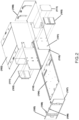
- FIG. 1 illustrates an example rack-mountable fiber optic splice enclosure 100.
- Splice enclosure 100 is designed to be mounted to front rails 301 of a standard 19" rack or a cabinet, and functions as a junction for fibers from one or more large count fiber optic cables 201 and equipment side fiber optic cables 203.
- splice enclosure 100 may be designed to be mounted to racks or cabinets of varying sizes.
- large count fiber optic cables 201 may be too rigid to be routed inside fiber optic splice enclosure 100, and therefore may be broken out into smaller, more flexible jacketed cables 202 at breakout box (or boxes) 200.
- Large count cables 201 may contain groups of jacketed cables 202 or sub-units, but those jackets may also be too rigid for tight bends inside fiber optic splice enclosure 100. The jackets may therefore be stripped from the sub-units and replaced with a flexible nylon or braided cable jacketing.
- Breakout box 200 may be attached to rear rails 302 of a rack or cabinet.
- a breakout box (not shown) may also be utilized on equipment side cables 203 if those cables are to be bundled into larger count cables, or to improve cable management.
- FIG. 2 illustrates an exploded view of rack-mountable fiber optic splice enclosure 100.
- fiber optic splice enclosure 100 may be made up of a body 101 having two opposing side walls, a bottom, and a cover 102 attached to body 101 with screws.
- Two guide rails 110 may be attached to the bottom of body 101 and may allow a sliding tray 104 to move linearly forward at least partially out of a front opening formed by body 101 and cover 102. Additionally, the two guide rails 110 may allow the sliding tray 104 to move backward at least partially out of a rear formed by body 101 and cover 102. Stops may be used to prevent sliding tray 104 from falling out once assembled.
- a removable rear panel 105 includes clips or latches 107 and 108 which removably secure front panel 105 and rear panel 106 to body 101 (clips/latches 107) and cover 102 (clips/latches 108) of fiber optic enclosure 100.
- a removable front panel 106 may include the same.
- Rear panel 105 and front panel 106 may be similar or identical, and one or both may include keyed locks 109 for additional security.
- Fiber optic splice enclosure 100 may be attached to equipment rails 301 of FIG. 1 with two mounting brackets 103.
- Mounting brackets 103 may have a plurality rows of through holes, which allow the installer to adjust the position of the mounting brackets 103 relative to the front of fiber optic splice enclosure 100 in order to control fiber optic splice enclosure 100's frontal projection.
- the rear of body 101 may include cable entry cutouts on either side which can be initially covered by access covers 111.
- Sliding tray 104 may serve as a platform to which splicing trays can be secured. Sliding tray 104 can be extended almost completely out of the front or the back of the enclosure body for installing or servicing of fiber optic splices.
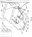
- FIG. 3 shows sliding tray 104 extended out the back opening of rack-mountable fiber optic splice enclosure 100.
- rear panel 106 shown in FIG. 2
- sliding tray 104 pulled at least partially out of the rear opening formed by body 101 and cover 102.
- One of access covers 111 is removed from one side of fiber optic splice enclosure 100 and replaced with a cable entry bracket 120.
- Cable entry bracket 120 has holes into which a variety of cable clips 204 can be installed to secure incoming cable 202 and equipment side cable 203.
- Cable plate 122 may be mounted to sliding tray 104 which provides an attachment location for cables 202 and 203. Cables 202 and 203 are looped on sliding tray 104 and secured to cable clips 204 on cable plate 122.
- the length of cables 202 and 203 between cable entry bracket 120 and cable plate 122 serve as slack and are routed with enough length to accommodate the movement of sliding tray 104 out the back and front of fiber optic splice enclosure 100.
- a splice tray bracket 130 to which splice trays 121 can be mounted, is attached to either the left or right side of sliding tray 104 depending on, and opposite of, the side that cables 202 and 203 enter fiber optic splice enclosure 100.
- Splice tray bracket 130 is attached to sliding tray 104 using thumb screws 123 through slotted mounting holes 124 to allow linear repositioning of splice tray bracket 130 on sliding tray 104.
- Incoming cables 202 and equipment side cables 203 are spliced together on splice trays 121.
- the large-radius edges of cable plate 122 provide bend radius control for cables 202 and 203 between cable plate 122 and splicing trays 121.
- Multiple cables can be spliced using the same method with additional cable clips 204 added to cable plate 122 and cable entry bracket 120 as needed to secure all cables 202 and 203.
- cable plate 122 to organize cables 202 and 203 vertically is beneficial because it simplifies future removal of splice trays 121 for service. Moreover, cables 202 and 203 attached to a splice tray 121 do not overlap from other splicing trays 121. Once the splicing work is complete, sliding tray 104 may be pushed back inside the fiber optic splice enclosure 100 and rear panel 106 reattached to enclosure 100.
- sliding tray 104 may also be pulled out through the front opening of fiber optic splice enclosure 100.
- front panel 105 shown in FIG. 2
- sliding tray 104 may be pulled at least partially out of enclosure 100 through the front opening formed by body 101 and cover 102. Sliding tray 104 may be returned to the home position in enclosure 100, and front panel 105 may be reattached to enclosure 100.
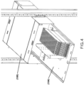
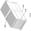
- FIGs. 5 and 6 show detailed views of splice tray bracket 130 holding a plurality of splice trays 121.
- splice tray bracket 130 holds splice trays 121 in an upright, vertical, or relatively vertical (near vertical) position.
- Splice tray bracket 130 includes cutouts or notches 131 designed to accept mounting pins 132 of splice trays 121. This allows splice trays 121 to rotate about mounting pins 132 of splice trays 121. The rotational characteristic of splice trays 121 allows the user to easily sort through splice trays 121.
- splicing trays 121 The rearward rotation of splicing trays 121 is limited by a stop plate 133 on the rear of splice tray bracket 130 and defines the orientation in which splicing trays 121 are stored.
- a strip of hook and loop 136 is looped through slots 134 and 135 of splice tray bracket 130 to keep splice trays 121 secured.
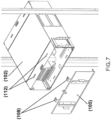
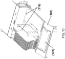
- FIGs. 7 to 10 illustrate the ability of removable rear panel 105 to be used as a holding/working surface for splice trays 121.
- upper latches 108 of removable rear panel 105 snap into cutouts 112 in cover 102.
- Upper latches 108 of removable rear panel 105 are also designed to be inserted into rear cutouts 113 in sliding tray 104 so that removable rear panel 105 can be attached to sliding tray 104 at an angle and serve as a holding/working surface for splice trays 121.
- a pair of handles 114 of removable rear panel 105 are designed to fit into the recessed portions 115 of splicing trays 121 to keep the splicing trays 121 stationary on removable rear panel 105.
- the front of sliding tray 104 also includes front cutouts 116 so that front removable panel 106 (shown in FIG. 2 ) can also be used as a holding/working surface in similar fashion to removable rear panel 105 when sliding tray 104 is pulled out of the front opening.
Landscapes
- Physics & Mathematics (AREA)
- General Physics & Mathematics (AREA)
- Optics & Photonics (AREA)
- Light Guides In General And Applications Therefor (AREA)
- Engineering & Computer Science (AREA)
- Computer Security & Cryptography (AREA)
- Mechanical Coupling Of Light Guides (AREA)
Claims (12)
- An einem Gestell montierbares Glasfaserspleißgehäuse, das Folgendes umfasst:einen Körper (101), umfassend zwei einander gegenüberliegende Seitenwände, einen Boden und eine Abdeckung;zwei Führungsschienen, die am Boden des Körpers befestigt sind;eine Gleitkassette, angeordnet auf den zwei Führungsschienen, wobei die Gleitkassette zumindest eine Spleißkassette umfasst; undeine erste entfernbare Platte (105), die über zumindest ein erstes Paar von Verriegelungen (108) entfernbar an der Abdeckung (102) befestigt ist und über ein zweites Paar von Verriegelungen (107) entfernbar am Boden befestigt ist, wobei die erste entfernbare Platte von der Abdeckung und vom Boden lösbar ist, undwobei die erste entfernbare Platte (105) über das erste Paar von Verriegelungen (108), die mit Ausschnitten (113) in der Gleitkassette in Eingriff sind, in einem Winkel an der Gleitkassette (104) befestigbar ist, während das zweite Paar von Verriegelungen vom Boden gelöst ist, um als eine Arbeitsoberfläche für die zumindest eine Spleißkassette zu dienen.
- An einem Gestell montierbares Glasfaserspleißgehäuse nach Anspruch 1, wobei die erste entfernbare Platte ein Paar Griffe (114) umfasst, die dazu ausgelegt sind, in eingesenkte Abschnitte (115) der zumindest einen Spleißkassette zu passen, wenn die zumindest eine Spleißkassette (121) an der ersten entfernbaren Platte befestigt ist, die als die Arbeitsoberfläche dient.
- An einem Gestell montierbares Glasfaserspleißgehäuse nach Anspruch 1, ferner umfassend: eine Spleißkassettenhalterung (130), montiert an der Gleitkassette, um die zumindest eine Spleißkassette in einer aufrechten Ausrichtung zu halten.
- An einem Gestell montierbares Glasfaserspleißgehäuse nach Anspruch 3, wobei die Spleißkassettenhalterung mehrere Kerben (131) zum Aufnehmen von Montagestiften (132) der zumindest einen Spleißkassette umfasst.
- An einem Gestell montierbares Glasfaserspleißgehäuse nach Anspruch 3, wobei die Spleißkassettenhalterung einen Klettverschlussstreifen umfasst, der durch mehrere Schlitze (134, 135) an der Spleißkassettenhalterung geschlungen ist, um die zumindest eine Spleißkassette an ihrem Platz zu sichern.
- An einem Gestell montierbares Glasfaserspleißgehäuse nach Anspruch 3, wobei die Spleißkassettenhalterung mehrere geschlitzte Montagelöcher (124) umfasst; und wobei die Spleißkassettenhalterung durch Einsetzen von Fingerschrauben durch die geschlitzten Montagelöcher an der Gleitkassette montiert wird.
- An einem Gestell montierbares Glasfaserspleißgehäuse nach Anspruch 6, wobei die geschlitzten Montagelöcher eine lineare Umpositionierung der Spleißkassettenhalterung auf der Gleitkassette ermöglichen.
- An einem Gestell montierbares Glasfaserspleißgehäuse nach Anspruch 1, ferner umfassend: eine zweite entfernbare Platte (106), die an einem der ersten entfernbaren Platte gegenüberliegenden Ende entfernbar an der Abdeckung und am Boden befestigt ist.
- An einem Gestell montierbares Glasfaserspleißgehäuse nach Anspruch 8, wobei die erste entfernbare Platte und die zweite entfernbare Platte jeweils ein Schlüsselschloss (109) umfassen.
- An einem Gestell montierbares Glasfaserspleißgehäuse nach Anspruch 1, ferner umfassend: eine an der Gleitkassette montierte Kabelplatte zum Bereitstellen von Befestigungsorten für Glasfaserkabel, die in das an einem Gestell montierbare Glasfaserspleißgehäuse hinein- und aus diesem herausführen.
- An einem Gestell montierbares Glasfaserspleißgehäuse nach Anspruch 10, ferner umfassend: mehrere an der Kabelplatte befestigte Kabelklemmen zum Sichern der Glasfaserkabel, die in das an einem Gestell montierbare Glasfaserspleißgehäuse hinein- und aus diesem herausführen.
- An einem Gestell montierbares Glasfaserspleißgehäuse nach Anspruch 10, wobei die Kabelplatte gerundete Kanten zum Bereitstellen von Biegeradiussteuerung umfasst.
Applications Claiming Priority (3)
| Application Number | Priority Date | Filing Date | Title |
|---|---|---|---|
| US201862631161P | 2018-02-15 | 2018-02-15 | |
| US16/257,188 US10641980B2 (en) | 2018-02-15 | 2019-01-25 | Rack-mountable fiber optic splice enclosure |
| PCT/US2019/015378 WO2019160672A1 (en) | 2018-02-15 | 2019-01-28 | Rack-mountable fiber optic splice enclosure |
Publications (2)
| Publication Number | Publication Date |
|---|---|
| EP3752875A1 EP3752875A1 (de) | 2020-12-23 |
| EP3752875B1 true EP3752875B1 (de) | 2024-10-02 |
Family
ID=67541536
Family Applications (1)
| Application Number | Title | Priority Date | Filing Date |
|---|---|---|---|
| EP19704703.8A Active EP3752875B1 (de) | 2018-02-15 | 2019-01-28 | An einem gestell montierbares glasfaserspleissgehäuse |
Country Status (5)
| Country | Link |
|---|---|
| US (1) | US10641980B2 (de) |
| EP (1) | EP3752875B1 (de) |
| JP (1) | JP7053861B2 (de) |
| CN (1) | CN214335308U (de) |
| WO (1) | WO2019160672A1 (de) |
Families Citing this family (5)
| Publication number | Priority date | Publication date | Assignee | Title |
|---|---|---|---|---|
| MX2020012100A (es) | 2018-05-14 | 2021-01-29 | Afl Telecommunications Llc | Cierres a tope y montajes organizadores para los mismos. |
| US12546964B2 (en) | 2020-09-28 | 2026-02-10 | Commscope Technologies Llc | Systems and methods for managing cables |
| US11971598B2 (en) | 2021-02-18 | 2024-04-30 | Commscope Technologies Llc | Tray arrangements for cassettes |
| WO2022178317A1 (en) | 2021-02-18 | 2022-08-25 | Commscope Technologies Llc | Communications panel system |
| WO2025069079A1 (en) * | 2023-09-29 | 2025-04-03 | Sterlite Technologies Limited | Optical fiber sub-unit |
Citations (1)
| Publication number | Priority date | Publication date | Assignee | Title |
|---|---|---|---|---|
| US5825962A (en) * | 1996-12-31 | 1998-10-20 | Siecor Corporation | Optical fiber splice housing |
Family Cites Families (37)
| Publication number | Priority date | Publication date | Assignee | Title |
|---|---|---|---|---|
| US4595255A (en) * | 1983-08-24 | 1986-06-17 | Fiberlan, Inc. | Optical fiber wiring center |
| FR2590371B1 (fr) * | 1985-11-18 | 1988-09-16 | Cit Alcatel | Chassis de tete de cables optiques |
| US4884863A (en) * | 1989-03-06 | 1989-12-05 | Siecor Corporation | Optical fiber splicing enclosure for installation in pedestals |
| US4971421A (en) * | 1989-09-29 | 1990-11-20 | Reliance Comm/Tec Corporation | Fiber optic splice and patch enclosure |
| US5208894A (en) * | 1990-07-16 | 1993-05-04 | Adc Telecommunications, Inc. | Fiber optic splice cabinet |
| US5546495A (en) | 1993-04-16 | 1996-08-13 | The Whitaker Corporation | Splice tray rack and cabinet for fiber optic cables |
| US5519804A (en) | 1994-06-22 | 1996-05-21 | At&T Corp. | Universal splice tray |
| US5835657A (en) | 1995-12-08 | 1998-11-10 | Psi Telecommunications, Inc. | Fiber optic splice tray |
| US6353183B1 (en) | 1996-05-23 | 2002-03-05 | The Siemon Company | Adapter plate for use with cable adapters |
| US5737475A (en) | 1997-01-17 | 1998-04-07 | Leviton Manufacturing Co., Inc. | Universal multimedia connection unit |
| JP2000089040A (ja) * | 1998-09-09 | 2000-03-31 | Sumitomo Electric Ind Ltd | 光配線収容ユニット |
| JP4026244B2 (ja) * | 1998-09-18 | 2007-12-26 | 住友電気工業株式会社 | 光成端架 |
| US6226436B1 (en) | 1999-11-18 | 2001-05-01 | Lucent Technologies, Inc. | Fiber optical pedestal |
| US6496640B1 (en) | 1999-12-16 | 2002-12-17 | Corning Cable Systems Llc | Splice closure with removable and pivotable splice trays, and associated methods |
| US6438310B1 (en) | 2000-01-24 | 2002-08-20 | Adc Telecommunications, Inc. | Cable management panel with sliding drawer |
| US6504988B1 (en) | 2000-01-24 | 2003-01-07 | Adc Telecommunications, Inc. | Cable management panel with sliding drawer |
| US6483977B2 (en) * | 2001-04-12 | 2002-11-19 | Corning Cable Systems Llc | Fiber management frame having movable work platform |
| US6748155B2 (en) | 2002-07-22 | 2004-06-08 | Adc Telecommunications, Inc. | Fiber management drawer and sliding cable slack limiter |
| US6944389B2 (en) | 2003-11-26 | 2005-09-13 | Corning Cable Systems Llc | Connector housing having a sliding tray with a hingeable portion |
| US7031588B2 (en) * | 2004-04-27 | 2006-04-18 | Commscope Solutions Properties, Llc | Articulated high density fiber optic splice and termination shelf |
| US8154886B2 (en) | 2007-03-27 | 2012-04-10 | Commscope, Inc. Of North Carolina | Compact fiber panel with sliding tray having removable hood |
| US7970249B2 (en) | 2008-02-15 | 2011-06-28 | Adc Telecommunications, Inc. | Fiber optic splice enclosure |
| CN102067003A (zh) | 2008-04-21 | 2011-05-18 | Adc电信公司 | 光纤接合盘 |
| US9519118B2 (en) * | 2010-04-30 | 2016-12-13 | Corning Optical Communications LLC | Removable fiber management sections for fiber optic housings, and related components and methods |
| US20110274402A1 (en) | 2010-05-07 | 2011-11-10 | Giraud William J | Removable fiber management devices for fiber optic housings, and related components and methods |
| US9008485B2 (en) * | 2011-05-09 | 2015-04-14 | Corning Cable Systems Llc | Attachment mechanisms employed to attach a rear housing section to a fiber optic housing, and related assemblies and methods |
| EP2533087A1 (de) | 2011-06-08 | 2012-12-12 | Tyco Electronics Raychem BVBA | Faserverwaltungsfach mit eingeschränktem Zugangsbereich |
| MX339488B (es) | 2011-07-11 | 2016-05-26 | Tyco Electronics Raychem Bvba | Caja de telecomunicaciones con ensamble de bandeja de empalme. |
| CA2848160A1 (en) * | 2011-09-09 | 2013-03-14 | Rich Cubala | Splice tray rail system |
| CN104520744B (zh) | 2012-04-03 | 2018-12-11 | 泰科电子瑞侃有限公司 | 电信机箱和理线器 |
| US9423585B2 (en) | 2014-01-31 | 2016-08-23 | Optical Cable Corporation | Fiber optic connectivity system |
| EP3102971B1 (de) * | 2014-02-03 | 2022-05-04 | The Siemon Company | Gestellmontierbares glasfasergehäuse |
| WO2015130759A1 (en) | 2014-02-25 | 2015-09-03 | Tyco Electronics Corporation | Modular elements tray |
| KR101718968B1 (ko) | 2014-09-22 | 2017-03-22 | 임채현 | 적층형 광심선 저장함 |
| JP6228638B1 (ja) * | 2016-07-11 | 2017-11-08 | 株式会社フジクラ | 光配線ユニット及び光部品収納ケース |
| CA3019081C (en) * | 2017-10-03 | 2025-05-06 | Belden Canada Ulc | MODULAR FIBER OPTIC CASSETTE, SYSTEM AND METHOD |
| CA3019068C (en) * | 2017-10-05 | 2025-01-07 | Belden Canada Ulc | SLIDING AND TILTING TRAY, SLIDING AND TRAY USING IT |
-
2019
- 2019-01-25 US US16/257,188 patent/US10641980B2/en active Active
- 2019-01-28 JP JP2020543537A patent/JP7053861B2/ja active Active
- 2019-01-28 WO PCT/US2019/015378 patent/WO2019160672A1/en not_active Ceased
- 2019-01-28 CN CN201990000462.XU patent/CN214335308U/zh active Active
- 2019-01-28 EP EP19704703.8A patent/EP3752875B1/de active Active
Patent Citations (1)
| Publication number | Priority date | Publication date | Assignee | Title |
|---|---|---|---|---|
| US5825962A (en) * | 1996-12-31 | 1998-10-20 | Siecor Corporation | Optical fiber splice housing |
Also Published As
| Publication number | Publication date |
|---|---|
| US10641980B2 (en) | 2020-05-05 |
| US20190250355A1 (en) | 2019-08-15 |
| EP3752875A1 (de) | 2020-12-23 |
| WO2019160672A1 (en) | 2019-08-22 |
| CN214335308U (zh) | 2021-10-01 |
| JP2021528675A (ja) | 2021-10-21 |
| JP7053861B2 (ja) | 2022-04-12 |
Similar Documents
| Publication | Publication Date | Title |
|---|---|---|
| US11988887B2 (en) | Optical fiber distribution system | |
| EP3752875B1 (de) | An einem gestell montierbares glasfaserspleissgehäuse | |
| US9075217B2 (en) | Apparatuses and related components and methods for expanding capacity of fiber optic housings | |
| US8965168B2 (en) | Fiber management devices for fiber optic housings, and related components and methods | |
| EP1621907B1 (de) | Verteilerkasten für optisches Kommunikationsnetzwerk | |
| US9519118B2 (en) | Removable fiber management sections for fiber optic housings, and related components and methods | |
| EP2646866B1 (de) | Faserorganisator und verteilerkasten | |
| US8705926B2 (en) | Fiber optic housings having a removable top, and related components and methods | |
| US7302153B2 (en) | Fiber management access system | |
| US9720195B2 (en) | Apparatuses and related components and methods for attachment and release of fiber optic housings to and from an equipment rack | |
| EP2127049B1 (de) | Abschlussanordnung für freileitungskabel | |
| US9632270B2 (en) | Fiber optic housings configured for tool-less assembly, and related components and methods | |
| US20110268408A1 (en) | Door fiber management for fiber optic housings, and related components and methods | |
| US8070112B2 (en) | Lateral storage spool for overhead cable pathway | |
| US20110274402A1 (en) | Removable fiber management devices for fiber optic housings, and related components and methods |
Legal Events
| Date | Code | Title | Description |
|---|---|---|---|
| STAA | Information on the status of an ep patent application or granted ep patent |
Free format text: STATUS: UNKNOWN |
|
| STAA | Information on the status of an ep patent application or granted ep patent |
Free format text: STATUS: THE INTERNATIONAL PUBLICATION HAS BEEN MADE |
|
| PUAI | Public reference made under article 153(3) epc to a published international application that has entered the european phase |
Free format text: ORIGINAL CODE: 0009012 |
|
| STAA | Information on the status of an ep patent application or granted ep patent |
Free format text: STATUS: REQUEST FOR EXAMINATION WAS MADE |
|
| 17P | Request for examination filed |
Effective date: 20200903 |
|
| AK | Designated contracting states |
Kind code of ref document: A1 Designated state(s): AL AT BE BG CH CY CZ DE DK EE ES FI FR GB GR HR HU IE IS IT LI LT LU LV MC MK MT NL NO PL PT RO RS SE SI SK SM TR |
|
| AX | Request for extension of the european patent |
Extension state: BA ME |
|
| DAV | Request for validation of the european patent (deleted) | ||
| DAX | Request for extension of the european patent (deleted) | ||
| STAA | Information on the status of an ep patent application or granted ep patent |
Free format text: STATUS: EXAMINATION IS IN PROGRESS |
|
| 17Q | First examination report despatched |
Effective date: 20220930 |
|
| GRAP | Despatch of communication of intention to grant a patent |
Free format text: ORIGINAL CODE: EPIDOSNIGR1 |
|
| STAA | Information on the status of an ep patent application or granted ep patent |
Free format text: STATUS: GRANT OF PATENT IS INTENDED |
|
| INTG | Intention to grant announced |
Effective date: 20240521 |
|
| GRAS | Grant fee paid |
Free format text: ORIGINAL CODE: EPIDOSNIGR3 |
|
| GRAA | (expected) grant |
Free format text: ORIGINAL CODE: 0009210 |
|
| STAA | Information on the status of an ep patent application or granted ep patent |
Free format text: STATUS: THE PATENT HAS BEEN GRANTED |
|
| AK | Designated contracting states |
Kind code of ref document: B1 Designated state(s): AL AT BE BG CH CY CZ DE DK EE ES FI FR GB GR HR HU IE IS IT LI LT LU LV MC MK MT NL NO PL PT RO RS SE SI SK SM TR |
|
| REG | Reference to a national code |
Ref country code: GB Ref legal event code: FG4D |
|
| REG | Reference to a national code |
Ref country code: CH Ref legal event code: EP |
|
| REG | Reference to a national code |
Ref country code: DE Ref legal event code: R096 Ref document number: 602019059687 Country of ref document: DE |
|
| REG | Reference to a national code |
Ref country code: IE Ref legal event code: FG4D |
|
| REG | Reference to a national code |
Ref country code: LT Ref legal event code: MG9D |
|
| REG | Reference to a national code |
Ref country code: NL Ref legal event code: MP Effective date: 20241002 |
|
| REG | Reference to a national code |
Ref country code: AT Ref legal event code: MK05 Ref document number: 1728903 Country of ref document: AT Kind code of ref document: T Effective date: 20241002 |
|
| PG25 | Lapsed in a contracting state [announced via postgrant information from national office to epo] |
Ref country code: NL Free format text: LAPSE BECAUSE OF FAILURE TO SUBMIT A TRANSLATION OF THE DESCRIPTION OR TO PAY THE FEE WITHIN THE PRESCRIBED TIME-LIMIT Effective date: 20241002 |
|
| PG25 | Lapsed in a contracting state [announced via postgrant information from national office to epo] |
Ref country code: NL Free format text: LAPSE BECAUSE OF FAILURE TO SUBMIT A TRANSLATION OF THE DESCRIPTION OR TO PAY THE FEE WITHIN THE PRESCRIBED TIME-LIMIT Effective date: 20241002 |
|
| PG25 | Lapsed in a contracting state [announced via postgrant information from national office to epo] |
Ref country code: HR Free format text: LAPSE BECAUSE OF FAILURE TO SUBMIT A TRANSLATION OF THE DESCRIPTION OR TO PAY THE FEE WITHIN THE PRESCRIBED TIME-LIMIT Effective date: 20241002 Ref country code: PT Free format text: LAPSE BECAUSE OF FAILURE TO SUBMIT A TRANSLATION OF THE DESCRIPTION OR TO PAY THE FEE WITHIN THE PRESCRIBED TIME-LIMIT Effective date: 20250203 Ref country code: IS Free format text: LAPSE BECAUSE OF FAILURE TO SUBMIT A TRANSLATION OF THE DESCRIPTION OR TO PAY THE FEE WITHIN THE PRESCRIBED TIME-LIMIT Effective date: 20250202 |
|
| PGFP | Annual fee paid to national office [announced via postgrant information from national office to epo] |
Ref country code: DE Payment date: 20250129 Year of fee payment: 7 |
|
| PG25 | Lapsed in a contracting state [announced via postgrant information from national office to epo] |
Ref country code: FI Free format text: LAPSE BECAUSE OF FAILURE TO SUBMIT A TRANSLATION OF THE DESCRIPTION OR TO PAY THE FEE WITHIN THE PRESCRIBED TIME-LIMIT Effective date: 20241002 |
|
| PG25 | Lapsed in a contracting state [announced via postgrant information from national office to epo] |
Ref country code: BG Free format text: LAPSE BECAUSE OF FAILURE TO SUBMIT A TRANSLATION OF THE DESCRIPTION OR TO PAY THE FEE WITHIN THE PRESCRIBED TIME-LIMIT Effective date: 20241002 |
|
| PG25 | Lapsed in a contracting state [announced via postgrant information from national office to epo] |
Ref country code: ES Free format text: LAPSE BECAUSE OF FAILURE TO SUBMIT A TRANSLATION OF THE DESCRIPTION OR TO PAY THE FEE WITHIN THE PRESCRIBED TIME-LIMIT Effective date: 20241002 |
|
| PG25 | Lapsed in a contracting state [announced via postgrant information from national office to epo] |
Ref country code: NO Free format text: LAPSE BECAUSE OF FAILURE TO SUBMIT A TRANSLATION OF THE DESCRIPTION OR TO PAY THE FEE WITHIN THE PRESCRIBED TIME-LIMIT Effective date: 20250102 |
|
| PG25 | Lapsed in a contracting state [announced via postgrant information from national office to epo] |
Ref country code: AT Free format text: LAPSE BECAUSE OF FAILURE TO SUBMIT A TRANSLATION OF THE DESCRIPTION OR TO PAY THE FEE WITHIN THE PRESCRIBED TIME-LIMIT Effective date: 20241002 Ref country code: LV Free format text: LAPSE BECAUSE OF FAILURE TO SUBMIT A TRANSLATION OF THE DESCRIPTION OR TO PAY THE FEE WITHIN THE PRESCRIBED TIME-LIMIT Effective date: 20241002 Ref country code: GR Free format text: LAPSE BECAUSE OF FAILURE TO SUBMIT A TRANSLATION OF THE DESCRIPTION OR TO PAY THE FEE WITHIN THE PRESCRIBED TIME-LIMIT Effective date: 20250103 |
|
| PG25 | Lapsed in a contracting state [announced via postgrant information from national office to epo] |
Ref country code: CZ Free format text: LAPSE BECAUSE OF FAILURE TO SUBMIT A TRANSLATION OF THE DESCRIPTION OR TO PAY THE FEE WITHIN THE PRESCRIBED TIME-LIMIT Effective date: 20241002 Ref country code: PL Free format text: LAPSE BECAUSE OF FAILURE TO SUBMIT A TRANSLATION OF THE DESCRIPTION OR TO PAY THE FEE WITHIN THE PRESCRIBED TIME-LIMIT Effective date: 20241002 |
|
| PGFP | Annual fee paid to national office [announced via postgrant information from national office to epo] |
Ref country code: FR Payment date: 20250127 Year of fee payment: 7 |
|
| PGFP | Annual fee paid to national office [announced via postgrant information from national office to epo] |
Ref country code: GB Payment date: 20250127 Year of fee payment: 7 |
|
| PG25 | Lapsed in a contracting state [announced via postgrant information from national office to epo] |
Ref country code: RS Free format text: LAPSE BECAUSE OF FAILURE TO SUBMIT A TRANSLATION OF THE DESCRIPTION OR TO PAY THE FEE WITHIN THE PRESCRIBED TIME-LIMIT Effective date: 20250102 |
|
| PG25 | Lapsed in a contracting state [announced via postgrant information from national office to epo] |
Ref country code: SM Free format text: LAPSE BECAUSE OF FAILURE TO SUBMIT A TRANSLATION OF THE DESCRIPTION OR TO PAY THE FEE WITHIN THE PRESCRIBED TIME-LIMIT Effective date: 20241002 |
|
| REG | Reference to a national code |
Ref country code: DE Ref legal event code: R097 Ref document number: 602019059687 Country of ref document: DE |
|
| PG25 | Lapsed in a contracting state [announced via postgrant information from national office to epo] |
Ref country code: DK Free format text: LAPSE BECAUSE OF FAILURE TO SUBMIT A TRANSLATION OF THE DESCRIPTION OR TO PAY THE FEE WITHIN THE PRESCRIBED TIME-LIMIT Effective date: 20241002 |
|
| PG25 | Lapsed in a contracting state [announced via postgrant information from national office to epo] |
Ref country code: EE Free format text: LAPSE BECAUSE OF FAILURE TO SUBMIT A TRANSLATION OF THE DESCRIPTION OR TO PAY THE FEE WITHIN THE PRESCRIBED TIME-LIMIT Effective date: 20241002 |
|
| PG25 | Lapsed in a contracting state [announced via postgrant information from national office to epo] |
Ref country code: RO Free format text: LAPSE BECAUSE OF FAILURE TO SUBMIT A TRANSLATION OF THE DESCRIPTION OR TO PAY THE FEE WITHIN THE PRESCRIBED TIME-LIMIT Effective date: 20241002 |
|
| PG25 | Lapsed in a contracting state [announced via postgrant information from national office to epo] |
Ref country code: SK Free format text: LAPSE BECAUSE OF FAILURE TO SUBMIT A TRANSLATION OF THE DESCRIPTION OR TO PAY THE FEE WITHIN THE PRESCRIBED TIME-LIMIT Effective date: 20241002 |
|
| PG25 | Lapsed in a contracting state [announced via postgrant information from national office to epo] |
Ref country code: IT Free format text: LAPSE BECAUSE OF FAILURE TO SUBMIT A TRANSLATION OF THE DESCRIPTION OR TO PAY THE FEE WITHIN THE PRESCRIBED TIME-LIMIT Effective date: 20241002 |
|
| PLBE | No opposition filed within time limit |
Free format text: ORIGINAL CODE: 0009261 |
|
| STAA | Information on the status of an ep patent application or granted ep patent |
Free format text: STATUS: NO OPPOSITION FILED WITHIN TIME LIMIT |
|
| REG | Reference to a national code |
Ref country code: CH Ref legal event code: PL |
|
| PG25 | Lapsed in a contracting state [announced via postgrant information from national office to epo] |
Ref country code: SE Free format text: LAPSE BECAUSE OF FAILURE TO SUBMIT A TRANSLATION OF THE DESCRIPTION OR TO PAY THE FEE WITHIN THE PRESCRIBED TIME-LIMIT Effective date: 20241002 |
|
| 26N | No opposition filed |
Effective date: 20250703 |
|
| PG25 | Lapsed in a contracting state [announced via postgrant information from national office to epo] |
Ref country code: MC Free format text: LAPSE BECAUSE OF FAILURE TO SUBMIT A TRANSLATION OF THE DESCRIPTION OR TO PAY THE FEE WITHIN THE PRESCRIBED TIME-LIMIT Effective date: 20241002 Ref country code: LU Free format text: LAPSE BECAUSE OF NON-PAYMENT OF DUE FEES Effective date: 20250128 |
|
| PG25 | Lapsed in a contracting state [announced via postgrant information from national office to epo] |
Ref country code: BE Free format text: LAPSE BECAUSE OF NON-PAYMENT OF DUE FEES Effective date: 20250131 |
|
| PG25 | Lapsed in a contracting state [announced via postgrant information from national office to epo] |
Ref country code: CH Free format text: LAPSE BECAUSE OF NON-PAYMENT OF DUE FEES Effective date: 20250131 |
|
| REG | Reference to a national code |
Ref country code: BE Ref legal event code: MM Effective date: 20250131 |
|
| PG25 | Lapsed in a contracting state [announced via postgrant information from national office to epo] |
Ref country code: IE Free format text: LAPSE BECAUSE OF NON-PAYMENT OF DUE FEES Effective date: 20250128 |