EP3841446B1 - Pressure reducing valve - Google Patents
Pressure reducing valve Download PDFInfo
- Publication number
- EP3841446B1 EP3841446B1 EP20725631.4A EP20725631A EP3841446B1 EP 3841446 B1 EP3841446 B1 EP 3841446B1 EP 20725631 A EP20725631 A EP 20725631A EP 3841446 B1 EP3841446 B1 EP 3841446B1
- Authority
- EP
- European Patent Office
- Prior art keywords
- region
- opening
- housing
- intermediate part
- valve
- Prior art date
- Legal status (The legal status is an assumption and is not a legal conclusion. Google has not performed a legal analysis and makes no representation as to the accuracy of the status listed.)
- Active
Links
- 238000007789 sealing Methods 0.000 claims description 54
- 239000012530 fluid Substances 0.000 claims description 6
- 238000001746 injection moulding Methods 0.000 claims description 4
- 239000002184 metal Substances 0.000 claims description 4
- 229920003023 plastic Polymers 0.000 claims description 4
- 239000004033 plastic Substances 0.000 claims description 4
- 230000006835 compression Effects 0.000 claims description 3
- 238000007906 compression Methods 0.000 claims description 3
- 238000011144 upstream manufacturing Methods 0.000 claims description 3
- 239000000463 material Substances 0.000 claims 1
- 239000012528 membrane Substances 0.000 description 53
- 230000000694 effects Effects 0.000 description 17
- 238000013461 design Methods 0.000 description 12
- 239000003638 chemical reducing agent Substances 0.000 description 11
- 239000007788 liquid Substances 0.000 description 11
- 238000004519 manufacturing process Methods 0.000 description 4
- 238000005192 partition Methods 0.000 description 4
- 230000002093 peripheral effect Effects 0.000 description 4
- 230000001419 dependent effect Effects 0.000 description 3
- 239000003651 drinking water Substances 0.000 description 3
- 235000020188 drinking water Nutrition 0.000 description 3
- 230000001105 regulatory effect Effects 0.000 description 3
- 230000036316 preload Effects 0.000 description 2
- 239000000565 sealant Substances 0.000 description 2
- 230000006978 adaptation Effects 0.000 description 1
- 238000010276 construction Methods 0.000 description 1
- 238000011109 contamination Methods 0.000 description 1
- 238000006073 displacement reaction Methods 0.000 description 1
- 230000002349 favourable effect Effects 0.000 description 1
- 239000007789 gas Substances 0.000 description 1
- 238000012423 maintenance Methods 0.000 description 1
- 238000005457 optimization Methods 0.000 description 1
- 230000002265 prevention Effects 0.000 description 1
- 238000012545 processing Methods 0.000 description 1
- 238000007493 shaping process Methods 0.000 description 1
- 238000012549 training Methods 0.000 description 1
- 230000007704 transition Effects 0.000 description 1
Images


Classifications
-
- G—PHYSICS
- G05—CONTROLLING; REGULATING
- G05D—SYSTEMS FOR CONTROLLING OR REGULATING NON-ELECTRIC VARIABLES
- G05D16/00—Control of fluid pressure
- G05D16/04—Control of fluid pressure without auxiliary power
- G05D16/06—Control of fluid pressure without auxiliary power the sensing element being a flexible membrane, yielding to pressure, e.g. diaphragm, bellows, capsule
- G05D16/063—Control of fluid pressure without auxiliary power the sensing element being a flexible membrane, yielding to pressure, e.g. diaphragm, bellows, capsule the sensing element being a membrane
- G05D16/0644—Control of fluid pressure without auxiliary power the sensing element being a flexible membrane, yielding to pressure, e.g. diaphragm, bellows, capsule the sensing element being a membrane the membrane acting directly on the obturator
- G05D16/0655—Control of fluid pressure without auxiliary power the sensing element being a flexible membrane, yielding to pressure, e.g. diaphragm, bellows, capsule the sensing element being a membrane the membrane acting directly on the obturator using one spring-loaded membrane
- G05D16/0658—Control of fluid pressure without auxiliary power the sensing element being a flexible membrane, yielding to pressure, e.g. diaphragm, bellows, capsule the sensing element being a membrane the membrane acting directly on the obturator using one spring-loaded membrane characterised by the form of the obturator
Definitions
- the invention relates to a pressure reducing valve for a liquid flowing through a line with a housing extending in an axial direction along a housing axis, in which a transverse, in particular, in a lower housing part between an upstream-side inlet area with a side inlet opening and a downstream-side outlet area with a side outlet opening perpendicular to the housing axis, an intermediate wall with a through opening and a pressure chamber arrangement are formed, which is separated from an adjustment space located above it in an upper part of the housing by means of a flexible membrane of a valve insert that is installed on the circumference of the housing, the pressure chamber arrangement being between the underside of the membrane and the top of a rigid one that is also installed in the housing , in particular rigid intermediate part, comprises an intermediate space and a flow space connected to it in a liquid-conducting manner via at least one through hole arranged in the intermediate part, the membrane being stationary in its central region with a valve tappet arranged axially parallel or coaxial to the housing axis and mov
- a pressure reducing valve of this type is in the EP 0 650 109 A1 reported as known.
- the pressure reducing valve has a housing extending along a housing axis with a lower housing part and an upper housing part screwed onto it in a connection area, with a membrane being clamped on the circumference as a control membrane in the connection area.
- a pressure reducer insert with a funnel-shaped insert housing, a valve seat and a valve tappet connected to the control membrane and a control membrane plate is inserted into an opening in the partition arranged perpendicular to the housing axis, which is at its lower End section carries a valve plate that interacts with the valve seat.
- the funnel-shaped insert housing is closed at its wide end by the control membrane and forms a control pressure chamber.
- a pressure reducing valve for gases or liquids in which an intermediate wall with a through opening is arranged in a lower housing part between an inlet area and an outlet area of a flow space, which is penetrated by a valve tappet.
- an intermediate part fixed to the housing is arranged between the exit region of the flow space and a membrane space, in which a fluid-conducting through hole is arranged in order to effect pressure regulation using the Venturi effect.
- the valve seat is connected to the insert housing of the pressure reducer insert via webs and is held sealingly in the opening of the partition, the webs containing channels which connect the outlet chamber with the control pressure chamber.
- a membrane pressure that is dependent on the pressure in the outlet chamber is generated in the control pressure chamber, which is directed in the opposite direction to a spring force acting on the membrane from the upper part of the housing, the spring force being directed in the opening direction of the pressure reducer insert and the membrane force in the closing direction of the pressure reducer insert, so that this
- the pressure level on the output side can be reduced to a certain level compared to an increased pressure on the input side by selecting the spring preload, as is usual with such pressure reducers.
- Another pressure reducing valve is in the DE 195 39 239 A1 specified.
- a pressure chamber arrangement with a membrane space closed by a membrane and a flow space separated therefrom by means of an intermediate part is arranged in a lower housing part, with an intermediate wall with a through opening being present between an upstream input area and a downstream output area, in which a A closing element connected to a valve tappet is displaceably guided in the axial direction of the housing.
- the intermediate part is provided with a sealing ring on its underside in an annular sealing area and a flow cross section between the underside of the intermediate part and the top of the closing element along the annular sealing area is adjustable, whereby a spring force acting on the valve tappet and a membrane force caused in the gap to adjust the closing element.
- a through hole is introduced between the exit area of the flow space and the membrane space in a housing section adjacent to the intermediate part in order to balance the spring force and membrane force. No further information is provided regarding the design of the through hole.
- a valve seat between an inlet chamber (upstream pressure chamber) and an outlet chamber (back pressure chamber) is held in a sealing manner in a partition wall present in the lower part of the housing at right angles to the housing axis and is provided with channels contained in webs of the valve seat, which connect the outlet chamber with a control pressure chamber (pressure chamber). , which is formed between the facing underside of a membrane and the top of a membrane carrier.
- a control pressure chamber pressure chamber
- a pressure reduction on the outlet side to a predeterminable pressure level is achieved by regulating a flow cross section between the lower edge of the valve seat and an associated valve plate in accordance with the balance between the spring force and the membrane force, the valve plate being connected to a valve tappet, on the upper section of which Membrane is attached.
- a Venturi effect associated with the flow in the back pressure chamber is used in order to additionally regulate the pressure in the pressure chamber depending on this.
- the bevel at the inlet of the pressure lines is directed radially outwards and downwards, with the flow on the valve plate, as in the version according to EP 0 650 109 A1 , on the input side from above on the valve plate.
- the present invention is based on the object of providing a pressure reducing valve of the type mentioned at the outset, which produces a precise function with as little manufacturing effort as possible.
- the closing element is guided in the axial direction in the through-opening of the intermediate wall, that the intermediate part is provided with a sealing ring on its underside in the sealing area and that the at least one through hole in the intermediate part is arranged radially outside the sealing ring immediately next to it or at a short distance smaller than half the inner radius of the sealing ring.
- the intermediate part is flowed into from below on its underside and the through hole(s) can be machined into the intermediate part with precise design and arrangement with relatively little effort , whereby the cross section of the through hole(s) does not have to be round, but can have different shapes, and the design of the underside of the intermediate part can be designed in exact coordination with the input contour, the shape and the arrangement of the through holes so that the in this Flow conditions prevailing in the area to achieve the most accurate possible Control can be optimized.
- the design options this opens up mean that, among other things, the Venturi effect can be used specifically and with great effectiveness to regulate the pressure level on the outlet side.
- An advantageous measure for the pressure control on the outlet side is that several through holes are arranged on an imaginary circular ring concentrically to the circular sealing ring and equidistant in the direction of rotation.
- a further advantageous embodiment for influencing the flow conditions and the associated pressure regulation is obtained in that the intermediate part is curved concavely in a radially symmetrical manner on its underside, starting from its central area on the valve tappet side, outwards into the area of the sealing ring, with the tangent along the in a central longitudinal plane extending curvature cross-section in the initial region of the curvature on the valve tappet side forms an angle ( ⁇ ) with the valve tappet axis between 0° and 45°, in particular between 0° and 30°, and in the end region on the ring seal side an angle ( ⁇ ) between 60° and 90°, in particular between 75° and 90°.
- the wall of the at least one through hole in its end face facing the flow space around the inlet opening in the radial direction outwards and towards the top compared to a cross-sectional plane perpendicular to the housing axis at an angle ( ⁇ ) is bevelled between 20° and 60°, in particular between 30° and 55°.
- the closing element is designed in such a way that the closing element has a circumferentially closed cylindrical section which is at least partially concentric to the housing axis, that the closing element is sealed on the circumference with the cylindrical section in the through opening of the intermediate wall, is guided in an axially displaceable manner, and that the closing element has at least one flow channel is provided in order to forward liquid flowing into the inlet area into the outlet area, an outlet opening of the flow channel leading to the outlet area lying radially within the sealing area.
- the closing element can advantageously be used and designed as a nozzle for flow to the underside of the intermediate part.
- the at least one flow channel runs parallel to the housing axis, at least in sections, in particular in its output section leading towards the output region.
- a flow channel or an arrangement of several flow channels is arranged concentrically to the housing axis.
- the resulting annular outflow area is advantageously located in the area of the radially symmetrical concave curvature of the intermediate part in an axial plan view.
- a valve cage is arranged in the entrance area between a liquid inlet and the closing element, the top of which adjoins the underside of the intermediate wall and with a sieve-like or grid-like peripheral wall surrounds the closing element at a distance.
- the membrane is covered on its upper side in a central surface area by a rigid, in particular rigid, membrane plate, on which a compression spring which effects the spring force on the membrane and the valve tappet is supported, the membrane can be flexibly deflected in the axial direction in an area lying radially outside the membrane plate and within its circumferential clamping area.
- the membrane is firmly clamped with its peripheral clamping area together with a peripheral clamping area of the intermediate part between the lower housing part and the upper housing part.
- valve tappet is guided in an axially displaceable manner in its upper section in the central through-opening of the intermediate part and in its lower section by means of the closing element firmly attached to it in the through-opening of the intermediate wall in order to achieve the flow cross-section defined pressure reduction, whereby the predetermined or predeterminable spring force and the membrane force balance each other.
- a design that is advantageous for production and function is that a spindle seal is present for the movable, liquid-tight passage of the valve tappet through the through opening of the intermediate part and that a circumferential annular groove is machined into the surface of the valve tappet the spindle seal is inserted, whereby it slidably cooperates with the through opening designed as a guide bore in a radially external sealing manner on the inner surface.
- valve spindle (valve tappet) can also be manufactured in a simplified manner, since good sliding properties do not have to be taken into account with regard to its surface quality and the groove can be easily formed in the outer surface.
- the inner surface of the guide hole can easily be manufactured with a high surface quality because no groove has to be machined.
- the part that is fixed to the housing and has the guide hole can be designed freely without taking into account the need for a sealing groove to be inserted.
- valve tappet or the valve spindle has a lower surface quality than the inner surface of the through opening, which is designed as a sliding surface, at least in the area of the annular groove and in its axially adjacent area.
- valve tappet or the valve spindle is made of metal and the housing-fixed intermediate part having the through opening, in particular a concentric middle part present therein, is made of plastic and/or metal.
- valve tappet (the valve spindle) can be turned as a rod in a simple manner, since low roughness and friction effects do not have to be taken into account.
- this can be the through opening in the form
- a housing-fixed part having a guide hole can be made of plastic, which results in a very good surface quality of the sliding surface (inner surface) compared to a turned part.
- the intermediate part is composed of at least two components, the at least two components comprising a middle part having the through opening designed as a guide hole and an outer ring surrounding it, then z. B. achieve a good adaptation of the intermediate part to different sub-functions, such as shaping a flow space, forming a clamping function in the valve housing and / or producing a guiding and sealing function in the middle area.
- sealing ring is inserted into a recess in the outer ring and is held by a radially outwardly projecting overlap of the middle part and that the intermediate part is manufactured in a two-component injection molding process.
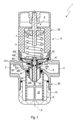
- Figure 1 shows a pressure reducing valve 1 (usually referred to as a pressure reducer for short) with a housing 5 extending in the direction of a housing axis A, which is composed of a lower housing part 50 with a lower cover part 51 and an upper housing part 52.
- the lower housing part 50 comprises an inflow-side input area 2 and an outflow-side output area 3, which are separated from one another in the area of an intermediate wall 53 arranged in a flow space 10 and lying at right angles to the housing axis A.
- the upper housing part 52 is screwed and sealed in a connection area by means of an external thread into an adapted internal thread of the lower housing part 50.
- the housing axis A can z. B. run obliquely at an angle of less than 90 ° with respect to an inlet or outlet port.
- an adjustment unit 8 with a compression spring 7 is arranged in an adjustment space 11, the preload of which can be preset to a defined spring force via adjustment components of the adjustment unit 8 in order to obtain a specific pressure level on the output side when the pressure reducing valve 1 is used.
- a pressure chamber arrangement is formed in the lower housing part 50, which is sealingly separated from the adjustment chamber 11 by means of a membrane 420 clamped at right angles to the housing axis A.
- the membrane is circumferentially between the Upper housing part 52 and the lower housing part 50 are clamped along a circumferential holding edge and are penetrated in their central area coaxially to the housing axis A by a valve tappet 43 and are sealed thereon and held in a stationary manner axially and immovably relative to this.
- the membrane 420 is provided in its central area surrounding the valve tappet 43 (valve spindle) with a membrane plate 422, on the upper side of which the underside of the spring 7 is supported, which is brought into position on its opposite upper side on a component of the adjusting unit 8 .
- the membrane 420 is clamped or clamped on the circumference with its retaining edge together with an outer ring 411 of an intermediate part 41 between the upper housing part 52 and the lower housing part 50 and, together with the top of the intermediate part 41 and its underside, forms an intermediate space 421 which is connected to the via through holes 412 output-side flow space 10 is connected in a liquid-conducting manner.
- the membrane 420 is designed to be flexible and is designed to be flexible in particular between its circumferentially clamped holding edge and the circumference of the membrane plate 422 spaced therefrom, so that it can be moved back and forth in the axial direction together with the valve tappet 43, i.e. up and down in the present case, in the intermediate space 421, as a result of the liquid pressure prevailing there via the through holes 412, a membrane force is generated on the underside of the membrane 420, which is directed in the opposite direction to the spring force acting on the upper side of the membrane.
- the membrane 420, with the valve tappet 43 attached to it in an axially immovable manner assumes a defined axial position depending on the fluid pressure present in the flow space 10.
- the valve tappet 43 is axially displaceable through a central through opening 414 of the intermediate part 41, with a middle part 410 being inserted, in particular screwed, into the central region of the outer ring 411 in the exemplary embodiment shown.
- the intermediate part 41 in this case the middle part 410, forms an axial guide for the valve tappet 43 with sealing by means of a circumferential groove (annular groove 431, see. Fig. 4 ) of the valve tappet 43 or alternatively in an inner groove of the middle part 410 inserted sealing element, such as. B. the spindle seal 430.
- the valve tappet 43 carries on its downward section a closing element 40 which is fixedly attached to it and thus moves axially together with it, which is provided with a peripheral cylindrical wall and is therefore displaceable and sealed into a through opening 530 in the central one
- the area of the intermediate wall 53 is inserted and guided concentrically to the housing axis A, with a sealant 44 being inserted into the wall surrounding the through-opening 530 in a circumferential groove.
- One or more flow channels 400 are introduced into the closing element 40, which in the exemplary embodiment shown run parallel to the housing axis A or the axis of the valve tappet and establish the flow connection between the inlet area 2 and the outlet area 3 in the flow space 10.
- a valve cage 6 surrounding the lower area of the closing element 40 is inserted, which is provided with a sieve on the circumference and is brought into contact with the underside of the intermediate wall 53 and extends into the lower cover part 51, which is removable and sealed a lower opening area of the lower housing part 50 is inserted, in particular screwed in, so that the valve cage 6 is freely accessible and cleanable from below.
- the upper frontal circumferential edge of the valve cage 6 simultaneously forms a Holder for the sealant 44 inserted into the circumferential groove on the underside of the intermediate wall 53.
- valve insert 4 which includes the membrane unit 42 with the membrane 420, with the intermediate space 421 and with the membrane plate 422, the intermediate part 41, the closing element 40 and the valve tappet 43, as in Figure 2 shown enlarged.
- the closing element 40 is provided in its upper edge area with a circumferential sealing edge or sealing surface 401, which forms a surface area that widens upwards and can be brought into sealing contact with a sealing ring 413 inserted circumferentially on the underside of the intermediate part 41 in order to control the flow of the To close liquid from the entrance area 2 to the exit area 3 via the flow space 10.
- a circumferential sealing edge or sealing surface 401 which forms a surface area that widens upwards and can be brought into sealing contact with a sealing ring 413 inserted circumferentially on the underside of the intermediate part 41 in order to control the flow of the To close liquid from the entrance area 2 to the exit area 3 via the flow space 10.
- the flow cross-section between the sealing surface 401 and the sealing ring 413 is opened so wide by the automatically regulating compensation between the spring force and the membrane force that a predetermined pressure level is established on the outlet side with different fluid pressures on the inlet side.
- the flow conditions in the flow space below the intermediate part 41 are specifically influenced in order to generate a significant Venturi effect, through which the pressure in the intermediate space 421 is reduced compared to the pressure further at the outlet and thus the membrane force and the valve opens further due to the spring force.
- the underside of the intermediate part 41 is rounded in a concave arcuate shape in the longitudinal section, with an angle between the housing axis and a tangent to the curve starting from the lower region adjacent to the valve tappet 43 being from one Value close to 0 ° increasingly changes to a value close to 90 ° in the region that is radially furthest outward (upper) of the valve tappet 43 and which overlaps the lower section of the sealing ring 413 that lies radially inward.
- This concave rounding of the intermediate part 41 which in the present case is formed in the middle part 410, runs radially symmetrically completely around the valve tappet 43 and extends with the radially outer region in an axial plan view up to the vicinity of the inner edge of the sealing surface 401 of the closing element 40 and is from this overlaps radially on the outside when closed.
- the liquid flowing into the flow space 10 on the input side is in the open state essentially axially parallel to the concave underside of the central region of the closing element by means of the flow channel 400, which is preferably arranged at least in sections around the valve tappet 43 in the circumferential direction and extends in the direction of the housing axis A 40 and from there deflected outwards and fed to the output-side connection of the output area 3.
- the closing element 40 thus forms a nozzle, by means of which the liquid flow is specifically shaped, particularly in the cross-sectional area between the sealing surface 401 and the sealing ring 413, with high effectiveness for generating the Venturi effect in the area of the through holes 412, with the underside entrances of the through holes 412 as close as possible, in particular are arranged immediately adjacent to the radially outer edge of the sealing ring 413.
- the lower opening edge of the through holes 412 is radially outwardly upwards at an angle ⁇ between 20 ° and 60 °, in particular, with respect to a central transverse plane of the valve tappet 43 (plane perpendicular to the housing axis A).
- the radially upper half of the outlet-side outflow section of the outlet area 3 as well as the radially upper half of the inlet-side inlet section of the inlet area 2 lie with respect to a transverse plane perpendicular to the housing axis A in the area of the circumferential opening cross-section between the sealing surface 401 and the underside of the sealing ring 413, the upper surface area of the input section and the output section lying approximately in the cross-sectional plane of the sealing ring 413.
- the through holes 412 which preferably extend parallel to the housing axis A, lie with their inlet openings on the underside on an imaginary circle with a diameter D relative to the housing axis or valve tappet axis.
- the flow space 10 in the area above the closing element 40 is rounded in longitudinal section in its area remote from the exit area 3.
- the flow is additionally influenced, in particular in cooperation with the upper outer surface area of the closing element 40, via which the flow deflected thereon is guided in the exit direction.
- the closing element 40 is beveled or rounded on its underside radially outwards and at the top, so that the flow channel 400 is designed to be streamlined at its flow-side entrance for introducing the inflowing liquid.
- the liquid passed through the flow channel 400 flows into the intermediate part 41 from below, which results in favorable flow conditions for the constant control of the pressure level on the outlet side.
- the flow-optimized geometry of the housing 5 and the valve insert 4 result in a design that is advantageous not only for the function of the pressure reducing valve 1, but also for its construction and maintenance, which offers significant advantages, particularly in the area of drinking water supply for households.
- the drinking water is passed past the sealing ring 413 through the outlet area 3 of the housing 5 into the subsequent pipeline.
- the pressure reduction takes place in the valve insert.
- the Venturi effect is achieved in the area of high flow velocity, whereby the pressure in the gap 421 under the membrane 420 is lower than the pressure further on the outlet side. This means that the membrane force is also lower and the spring force is significantly higher in comparison, which means that the valve opens further. This creates a lower flow resistance and therefore a lower pressure loss at corresponding flow rates. Negative friction effects can thus be reduced or completely compensated for, thereby increasing the control accuracy. Because in practice the output pressure drops, when the flow increases, which is due, among other things, to friction effects, spring rates, internal restoring forces and changes in the effective diameter of the membrane. With the structure described above, the sealing ring 413 is not movable but is fixedly clamped to the intermediate part 41, thereby reducing vibrations and associated undesirable noise.
- the spindle seal 430 is inserted into the annular groove 431 of the valve tappet 43 and the through hole 414 is axially expanded in the middle part 410 and forms a guide bore for the valve tappet 43, which is slidably guided therein in a sealed manner by means of the spindle seal 430.
- This is the axial extent of the through hole 414 dimensioned sufficiently long to ensure sealing by means of the spindle seal 430 over the entire axial adjustment stroke of the valve tappet 43.
- This is also advantageously achieved in connection with the concave, radially symmetrical circumferential outer curvature of the intermediate part 41, in particular the middle part 410.
- the spindle seal 430 inserted into the annular groove 431 of the valve tappet 43 seals with its radially outer side the passage of the valve tappet 43 in the guide bore or through opening 414 with sliding guidance.
- the valve tappet 43 has a constant, in particular circular-cylindrical, cross section, at least in its passage area through the through opening 414, including its adjustment area.
- the inner surface or sliding surface of the intermediate part 41, in particular the middle part 410, surrounding the through opening 414 has a high surface quality, ie low roughness or roughness depth, for good sliding properties. As a result of this design, the valve tappet 43 only requires a low surface quality relative to the sliding surface and can be correspondingly cheap, for example. B.
- the intermediate part 41 can be made of plastic at least in the area of the through opening 414 or the middle part 410 inserted in its central area.
- B. can be produced using injection molding, which means that a correspondingly high surface quality can be achieved with simple measures.
- the intermediate part 41 has in the center the inner part or middle part 410 provided with the through opening 414 and the outer ring 411 connected to it and surrounding it.
- a recess is made in the outer ring 411 in the transition area to the middle part 410, into which the sealing ring 413, which interacts with the sealing surface 401 of the closing element 40, is inserted.
- the sealing ring 413 is held on its underside in a radially inner area by means of a radially outwardly projecting edge of the middle part 410, so that its radially outer underside offers sufficient area for sealing in cooperation with the sealing surface 401.
- the middle part 410 can have a relatively large axial extension in its central area around the through opening 414, so that good guidance and sufficient sliding path for the spindle seal 430 result for the axial displacement of the valve tappet 43, as explained above.
- the intermediate part 41 which is z. B. is formed from two or more components (middle part, outer ring, sealing ring), can advantageously be manufactured in a two-component injection molding process, whereby simple assembly is achieved.
- the design shown with the radially externally sealing spindle seal 430 in the guide bore 414 lays the foundation for a manufacturing optimization of valves, especially in connection with the application in Drinking water area, such as B. in pressure reducers, but also offers advantages in comparable other valves with a guided valve tappet 43 or guided valve spindle, as in the underlying priority application DE 20 2019 102 814.9 explained.
Description
Die Erfindung bezieht sich auf ein Druckminderungsventil für eine durch eine Leitung strömende Flüssigkeit mit einem sich in einer axialen Richtung entlang einer Gehäuseachse erstreckenden Gehäuse, in dem in einem Gehäuseunterteil zwischen einem stromaufseitigen Eingangsbereich mit seitlicher Eingangsöffnung und einem stromabseitigen Ausgangsbereich mit seitlicher Ausgangsöffnung eine quer, insbesondere rechtwinklig zur Gehäuseachse liegende Zwischenwand mit Durchführöffnung und eine Druckraumanordnung ausgebildet sind, welche von einem darüber in einem Gehäuseoberteil befindlichen Einstellraum mittels einer umfangsseitig gehäusefest eingebauten flexiblen Membran eines Ventileinsatzes getrennt ist, wobei die Druckraumanordnung zwischen der Unterseite der Membran und der Oberseite eines ebenfalls gehäusefest eingebauten biegesteifen, insbesondere starren Zwischenteils einen Zwischenraum und einen mit diesem über mindestens eine in dem Zwischenteil angeordnete Durchgangsbohrung flüssigkeitsleitend in Verbindung gebrachten Durchströmungsraum umfasst, wobei die Membran in ihrem zentralen Bereich mit einem achsparallel oder koaxial zur Gehäuseachse angeordneten und in axialer Richtung hin und her beweglichen Ventilstößel ortsfest und flüssigkeitsdicht verbunden ist, welcher sich flüssigkeits-gedichtet verschieblich durch eine zentrale Durchgangsöffnung des Zwischenteils in den Durchströmungsraum erstreckt und in diesem ortsfest mit einem Schließelement verbunden ist, und wobei ein Strömungsquerschnitt zwischen der Unterseite des Zwischenteils und der Oberseite des Schließelements entlang eines ringförmigen Dichtbereichs einstellbar ist, indem eine auf den Ventilstößel mittels einer vorgespannten Feder wirkende Federkraft zum Verstellen des Schließelements in Öffnungsrichtung unter Erweitern des Strömungsquerschnitts wirkt und eine durch den Flüssigkeitsdruck in dem Zwischenraum bewirkte Membrankraft zum Verstellen des Schließelements in Schließrichtung unter Verengen des Strömungsquerschnitts wirkt und eine Einstellung des Strömungsquerschnitts sich durch Ausgleich von Federkraft und Membrankraft ergibt.The invention relates to a pressure reducing valve for a liquid flowing through a line with a housing extending in an axial direction along a housing axis, in which a transverse, in particular, in a lower housing part between an upstream-side inlet area with a side inlet opening and a downstream-side outlet area with a side outlet opening perpendicular to the housing axis, an intermediate wall with a through opening and a pressure chamber arrangement are formed, which is separated from an adjustment space located above it in an upper part of the housing by means of a flexible membrane of a valve insert that is installed on the circumference of the housing, the pressure chamber arrangement being between the underside of the membrane and the top of a rigid one that is also installed in the housing , in particular rigid intermediate part, comprises an intermediate space and a flow space connected to it in a liquid-conducting manner via at least one through hole arranged in the intermediate part, the membrane being stationary in its central region with a valve tappet arranged axially parallel or coaxial to the housing axis and movable back and forth in the axial direction and is connected in a liquid-tight manner, which extends in a liquid-tight manner through a central passage opening of the intermediate part into the flow space and is connected in a stationary manner to a closing element, and wherein a flow cross section between the underside of the intermediate part and the top of the closing element can be adjusted along an annular sealing area is in that a spring force acting on the valve tappet by means of a preloaded spring acts to adjust the closing element in the opening direction while expanding the flow cross section and a membrane force caused by the liquid pressure in the gap acts to adjust the closing element in the closing direction while narrowing the flow cross section and an adjustment of the flow cross section results from balancing the spring force and membrane force.
Ein Druckminderungsventil dieser Art ist in der
In der
Ähnliche Druckminderungsventile wie die
Weitere Druckminderungsventile, bei denen zur Druckregulierung der Venturi-Effekt genutzt wird, sind in der
Der Ventilsitz ist über Stege mit dem Einsatzgehäuse des Druckminderereinsatzes verbunden und abdichtend in dem Durchbruch der Trennwand gehalten, wobei die Stege Kanäle enthalten, welche die Auslasskammer mit der Regeldruckkammer verbinden. Aus diese Weise wird in der Regeldruckkammer ein von dem Druck in der Auslasskammer abhängiger Membrandruck erzeugt, der einer auf die Membran vom Gehäuseoberteil aus wirkenden Federkraft entgegengerichtet ist, wobei die Federkraft in Öffnungsrichtung des Druckminderereinsatzes und die Membrankraft in Schließrichtung des Druckminderereinsatzes gerichtet ist, sodass das ausgangsseitige Druckniveau gegenüber einem erhöhten eingangsseitigen Druck durch Wahl der Federvorspannung auf ein bestimmtes Maß reduzierbar ist, wie bei derartigen Druckminderern üblich.The valve seat is connected to the insert housing of the pressure reducer insert via webs and is held sealingly in the opening of the partition, the webs containing channels which connect the outlet chamber with the control pressure chamber. In this way, a membrane pressure that is dependent on the pressure in the outlet chamber is generated in the control pressure chamber, which is directed in the opposite direction to a spring force acting on the membrane from the upper part of the housing, the spring force being directed in the opening direction of the pressure reducer insert and the membrane force in the closing direction of the pressure reducer insert, so that this The pressure level on the output side can be reduced to a certain level compared to an increased pressure on the input side by selecting the spring preload, as is usual with such pressure reducers.
Ein weiteres Druckminderungsventil ist in der
Ein weiterer Druckminderer dieser Art ist in der
Um eine präzise Funktion insbesondere auch hinsichtlich einer genauen Regelung des ausgangsseitigen Druckniveaus zu erreichen, sind bei derartigen Druckminderern hohe Anforderungen an eine präzise Bearbeitung zu stellen, womit ein entsprechender Aufwand verbunden ist.In order to achieve a precise function, especially with regard to precise control of the pressure level on the outlet side, such pressure reducers have to place high demands on precise processing, which entails a corresponding effort.
Der vorliegenden Erfindung liegt die Aufgabe zugrunde, ein Druckminderungsventil der eingangs genannten Art bereitzustellen, das eine präzise Funktion bei möglichst wenig Herstellungsaufwand ergibt.The present invention is based on the object of providing a pressure reducing valve of the type mentioned at the outset, which produces a precise function with as little manufacturing effort as possible.
Diese Aufgabe wird bei einem Druckminderungsventil mit den Merkmalen des Anspruchs 1 gelöst. Hierbei ist in Verbindung mit der Ausbildung nach dem Oberbegriff des Weiteren vorgesehen, dass das Schließelement in der Durchführöffnung der Zwischenwand in axialer Richtung verschieblich geführt ist, dass das Zwischenteil auf seiner Unterseite in dem Dichtbereich mit einem Dichtring versehen ist und dass die mindestens eine Durchgangsbohrung in dem Zwischenteil radial außerhalb des Dichtrings unmittelbar neben diesem oder in geringem Abstand kleiner als der halbe Innenradius des Dichtrings von diesem angeordnet ist.This task is achieved with a pressure reducing valve with the features of
Bei diesem Aufbau mit dem verschieblich in der Zwischenwand abgedichtet geführten Schließelement und dem darüber membranseitig angeordneten Zwischenteil wird das Zwischenteil von unten auf seiner Unterseite angeströmt und die Durchgangsbohrung(en) kann/können unter präziser Ausbildung und Anordnung mit relativ wenig Aufwand in das Zwischenteil eingearbeitet werden, wobei der Querschnitt der Durchgangsbohrung(en) nicht rund sein muss, sondern unterschiedliche Form aufweisen kann, und die Gestaltung der Unterseite des Zwischenteils in exakter Abstimmung auf die Eingangskontur, die Formung und die Anordnung der Durchgangsbohrungen so ausgebildet werden kann, dass die in diesem Bereich vorherrschenden Strömungsverhältnisse zum Erreichen einer möglichst genauen Regelung optimiert werden können. Durch die dabei eröffneten Gestaltungsmöglichkeiten lässt sich unter anderem der Venturi-Effekt gezielt mit hoher Wirksamkeit für die Regelung des ausgangsseitigen Druckniveaus nutzen.In this structure with the closing element, which is displaceably sealed in the intermediate wall and the intermediate part arranged above it on the membrane side, the intermediate part is flowed into from below on its underside and the through hole(s) can be machined into the intermediate part with precise design and arrangement with relatively little effort , whereby the cross section of the through hole(s) does not have to be round, but can have different shapes, and the design of the underside of the intermediate part can be designed in exact coordination with the input contour, the shape and the arrangement of the through holes so that the in this Flow conditions prevailing in the area to achieve the most accurate possible Control can be optimized. The design options this opens up mean that, among other things, the Venturi effect can be used specifically and with great effectiveness to regulate the pressure level on the outlet side.
Eine für die ausgangsseitige Druckregelung vorteilhafte Maßnahme besteht dabei darin, dass mehrere Durchgangsbohrungen auf einem gedachten Kreisring konzentrisch zu dem kreisförmigen Dichtring und in Umlaufrichtung äquidistant angeordnet sind.An advantageous measure for the pressure control on the outlet side is that several through holes are arranged on an imaginary circular ring concentrically to the circular sealing ring and equidistant in the direction of rotation.
Eine für die Beeinflussung der Strömungsverhältnisse und damit zusammenhängend der Druckregulierung weitere vorteilhafte Ausgestaltung wird dadurch erhalten, dass das Zwischenteil auf seiner Unterseite ausgehend von seinem ventilstößelseitigen zentralen Bereich nach außen hin bis in den Bereich des Dichtrings radialsymmetrisch konkav gewölbt ist, wobei die Tangente entlang des in einer Mittellängsebene verlaufenden Wölbungsquerschnitts im ventilstößelseitigen Anfangsbereich der Wölbung mit der Ventilstößelachse einen Winkel (β) zwischen 0° und 45°, insbesondere zwischen 0° und 30°, bildet und in dem ringdichtungsseitigen Endbereich einen Winkel (γ) zwischen 60° und 90°, insbesondere zwischen 75° und 90°, bildet.A further advantageous embodiment for influencing the flow conditions and the associated pressure regulation is obtained in that the intermediate part is curved concavely in a radially symmetrical manner on its underside, starting from its central area on the valve tappet side, outwards into the area of the sealing ring, with the tangent along the in a central longitudinal plane extending curvature cross-section in the initial region of the curvature on the valve tappet side forms an angle (β) with the valve tappet axis between 0° and 45°, in particular between 0° and 30°, and in the end region on the ring seal side an angle (γ) between 60° and 90°, in particular between 75° and 90°.
Weitere vorteilhafte Maßnahmen zur Beeinflussung der Strömungsverhältnisse und für eine effektive Regelung bestehen darin, dass die Wandung der mindestens einen Durchgangsbohrung in ihrer dem Durchströmungsraum zugekehrten Stirnseite um die Eingangsöffnung in radialer Richtung nach außen und zur Oberseite hin gegenüber einer zur Gehäuseachse rechtwinkligen Querschnittsebene unter einem Winkel (α) zwischen 20° und 60°, insbesondere zwischen 30° und 55°, abgeschrägt ist.Further advantageous measures for influencing the flow conditions and for effective control are that the wall of the at least one through hole in its end face facing the flow space around the inlet opening in the radial direction outwards and towards the top compared to a cross-sectional plane perpendicular to the housing axis at an angle ( α) is bevelled between 20° and 60°, in particular between 30° and 55°.
Das Schließelement ist so ausgeführt, dass das Schließelement einen zumindest abschnittsweise zur Gehäuseachse konzentrischen, umlaufend geschlossenen zylindrischen Abschnitt aufweist, dass das Schließelement mit dem zylindrischen Abschnitt in der Durchführöffnung der Zwischenwand umfangsseitig abgedichtet, axial verschlieblich geführt ist, und dass das Schließelement mit mindestens einem Durchströmkanal versehen ist, um in den Eingangsbereich strömende Flüssigkeit in den Ausgangsbereich weiterzuleiten, wobei eine zum Ausgangsbereich führende Ausgangsöffnung des Durchströmkanals radial innerhalb des Dichtbereichs liegt. Dadurch kann das Schließelement vorteilhaft als Düse zum Anströmen der Unterseite des Zwischenteils genutzt und gestaltet werden.The closing element is designed in such a way that the closing element has a circumferentially closed cylindrical section which is at least partially concentric to the housing axis, that the closing element is sealed on the circumference with the cylindrical section in the through opening of the intermediate wall, is guided in an axially displaceable manner, and that the closing element has at least one flow channel is provided in order to forward liquid flowing into the inlet area into the outlet area, an outlet opening of the flow channel leading to the outlet area lying radially within the sealing area. As a result, the closing element can advantageously be used and designed as a nozzle for flow to the underside of the intermediate part.
Für den Aufbau und die Funktion trägt weiterhin vorteilhaft bei, dass der mindestens eine Durchströmkanal zumindest abschnittsweise, insbesondere in seinem zum Ausgangsbereich hin führenden Ausgangsabschnitt, parallel zur Gehäuseachse verläuft.Another advantage for the structure and function is that the at least one flow channel runs parallel to the housing axis, at least in sections, in particular in its output section leading towards the output region.
Verschiedene weitere vorteilhafte Ausbildungen werden dadurch erhalten, dass ein Durchströmkanal oder eine Anordnung aus mehreren Durchströmkanälen konzentrisch zur Gehäuseachse angeordnet ist. Vorteilhaft liegt dabei der sich ergebende kreisringförmige Ausströmbereich in axialer Draufsicht im Bereich der radialsymmetrischen konkaven Wölbung des Zwischenteils.Various further advantageous embodiments are obtained in that a flow channel or an arrangement of several flow channels is arranged concentrically to the housing axis. The resulting annular outflow area is advantageously located in the area of the radially symmetrical concave curvature of the intermediate part in an axial plan view.
Für den Aufbau und die Funktion, wie Schutz und Vermeidung von Verschmutzung, sind des Weiteren die Maßnahmen von Vorteil, dass im Eingangsbereich zwischen einem Flüssigkeitseinlass und dem Schließelement ein Ventilkäfig angeordnet ist, der sich mit seiner Oberseite an die Unterseite der Zwischenwand anschließt und mit einer siebartigen oder gitterartigen Umfangswand das Schließelement unter Abstand umgibt.For the structure and function, such as protection and prevention of contamination, the measures are also advantageous: a valve cage is arranged in the entrance area between a liquid inlet and the closing element, the top of which adjoins the underside of the intermediate wall and with a sieve-like or grid-like peripheral wall surrounds the closing element at a distance.
Der Aufbau und die Funktion werden auch dadurch begünstigt, dass die Membran auf ihrer Oberseite in einem mittleren Flächenbereich von einem biegesteifen, insbesondere starren, Membranteller abgedeckt ist, auf dem eine die Federkraft auf die Membran und den Ventilstößel bewirkende Druckfeder abgestützt ist, wobei die Membran in einem radialseitig außerhalb des Membrantellers und innerhalb ihres umfangsseitigen Einspannbereichs liegenden Bereich flexibel in axialer Richtung auslenkbar ist.The structure and function are also favored by the fact that the membrane is covered on its upper side in a central surface area by a rigid, in particular rigid, membrane plate, on which a compression spring which effects the spring force on the membrane and the valve tappet is supported, the membrane can be flexibly deflected in the axial direction in an area lying radially outside the membrane plate and within its circumferential clamping area.
Vorteile für den Aufbau und die Funktion ergeben sich auch dadurch, dass die Membran mit ihrem umfangsseitigen Einspannbereich zusammen mit einem umfangsseitigen Einspannbereich des Zwischenteils zwischen dem Gehäuseunterteil und dem Gehäuseoberteil fest eingeklemmt ist.Advantages for the structure and function also result from the fact that the membrane is firmly clamped with its peripheral clamping area together with a peripheral clamping area of the intermediate part between the lower housing part and the upper housing part.
Weitere Vorteile für das Druckminderungsventil ergeben sich daraus, dass der Ventilstößel in seinem oberen Abschnitt in der zentralen Durchgangsöffnung des Zwischenteils und in seinem unteren Abschnitt vermittels des fest an ihm angebrachten Schließelements in der Durchführöffnung der Zwischenwand axial verschieblich geführt ist, um den Strömungsquerschnitt zum Erreichen einer definierten Druckminderung zu verändern, wobei sich die vorgegebene oder vorgebbare Federkraft und die Membrankraft ausgleichen.Further advantages for the pressure reducing valve result from the fact that the valve tappet is guided in an axially displaceable manner in its upper section in the central through-opening of the intermediate part and in its lower section by means of the closing element firmly attached to it in the through-opening of the intermediate wall in order to achieve the flow cross-section defined pressure reduction, whereby the predetermined or predeterminable spring force and the membrane force balance each other.
Eine für die Herstellung und Funktion vorteilhafte Ausbildung besteht darin, dass zur verschieblichen flüssigkeitsgedichteten Durchführung des Ventilstößels durch die Durchgangsöffnung des Zwischenteils eine Spindeldichtung vorhanden ist und dass in die Oberfläche des Ventilstößels eine umlaufende Ringnut eingearbeitet ist, in die die Spindeldichtung eingesetzt ist, wobei sie radial außen dichtend auf der Innenfläche der als Führungsbohrung ausgestalteten Durchgangsöffnung gleitend mit dieser zusammenwirkt.A design that is advantageous for production and function is that a spindle seal is present for the movable, liquid-tight passage of the valve tappet through the through opening of the intermediate part and that a circumferential annular groove is machined into the surface of the valve tappet the spindle seal is inserted, whereby it slidably cooperates with the through opening designed as a guide bore in a radially external sealing manner on the inner surface.
Mit diesen Maßnahmen werden bei vereinfachtem Aufbau erweiterte Gestaltungsmöglichkeiten erhalten, wobei gleichzeitig eine zuverlässige Führungs- und Dichtfunktion gewährleistet sind. Insgesamt lässt sich dabei auch die Ventilspindel (Ventilstößel) vereinfacht herstellen, da bezüglich ihrer Oberflächenbeschaffenheit nicht auf gute Gleiteigenschaften geachtet werden muss und die Nut in der Außenfläche einfach ausgebildet werden kann. Hingegen kann die Innenfläche der Führungsbohrung einfach mit hoher Oberflächengüte hergestellt werden, da keine Nut eingearbeitet werden muss. Das die Führungsbohrung aufweisende gehäusefeste Teil kann ohne Rücksicht auf eine einzubringende Dichtungsnut frei gestaltet werden.With these measures, expanded design options are achieved with a simplified structure, while at the same time a reliable guiding and sealing function is guaranteed. Overall, the valve spindle (valve tappet) can also be manufactured in a simplified manner, since good sliding properties do not have to be taken into account with regard to its surface quality and the groove can be easily formed in the outer surface. On the other hand, the inner surface of the guide hole can easily be manufactured with a high surface quality because no groove has to be machined. The part that is fixed to the housing and has the guide hole can be designed freely without taking into account the need for a sealing groove to be inserted.
Dabei besteht eine für die Fertigung vorteilhafte Ausgestaltung darin, dass der Ventilstößel bzw. die Ventilspindel zumindest im Bereich der Ringnut und in ihrem axial an diese angrenzenden Bereich eine geringere Oberflächengüte aufweist als die als Gleitfläche ausgebildete Innenfläche der Durchgangsöffnung.An advantageous embodiment for production is that the valve tappet or the valve spindle has a lower surface quality than the inner surface of the through opening, which is designed as a sliding surface, at least in the area of the annular groove and in its axially adjacent area.
Weitere vorteilhafte Ausführungsformen ergeben sich dadurch, dass der Ventilstößel bzw. die Ventilspindel aus Metall und das die Durchgangsöffnung aufweisende gehäusefeste Zwischenteil, insbesondere ein darin vorhandenes konzentrisches Mitteilteil, aus Kunststoff und/oder Metall besteht.Further advantageous embodiments result from the fact that the valve tappet or the valve spindle is made of metal and the housing-fixed intermediate part having the through opening, in particular a concentric middle part present therein, is made of plastic and/or metal.
Beispielsweise kann dadurch der Ventilstößel (die Ventilspindel) als Stange in einfacher Fertigung gedreht werden, da dabei nicht auf eine geringe Rauigkeit und Reibeffekte zu achten ist. Beispielsweise kann das die Durchgangsöffnung in Form einer Führungsbohrung aufweisende gehäusefeste Teil aus Kunststoff ausgebildet sein, wodurch sich fertigungstechnisch eine im Vergleich zu einem gedrehten Teil sehr gute Oberflächengüte der Gleitfläche (Innenfläche) ergibt.For example, the valve tappet (the valve spindle) can be turned as a rod in a simple manner, since low roughness and friction effects do not have to be taken into account. For example, this can be the through opening in the form A housing-fixed part having a guide hole can be made of plastic, which results in a very good surface quality of the sliding surface (inner surface) compared to a turned part.
Ist vorgesehen, dass das Zwischenteil aus mindestens zwei Komponenten zusammengesetzt ist, wobei die mindestens zwei Komponenten einen die als Führungsbohrung ausgebildete Durchgangsöffnung aufweisenden Mittelteil und einen diesen umgebenden Außenring umfassen, so lässt sich z. B. eine gute Anpassung des Zwischenteils an unterschiedliche Teilfunktionen, wie Formung eines Strömungsraums, Ausbildung einer Einspannfunktion in dem Ventilgehäuse und/oder Herstellung einer Führungs- und Dichtfunktion im mittleren Bereich erreichen.If it is provided that the intermediate part is composed of at least two components, the at least two components comprising a middle part having the through opening designed as a guide hole and an outer ring surrounding it, then z. B. achieve a good adaptation of the intermediate part to different sub-functions, such as shaping a flow space, forming a clamping function in the valve housing and / or producing a guiding and sealing function in the middle area.
Für den Aufbau und die Funktion weitere vorteilhafte Maßnahmen bestehen darin, dass der Dichtring in eine Ausnehmung des Außenrings eingesetzt ist und von einer radial nach außen vorstehenden Überlappung des Mittelteils gehalten ist und darin, dass das Zwischenteil in einem Zweikomponenten-Spritzgussverfahren hergestellt ist.Further advantageous measures for the structure and function are that the sealing ring is inserted into a recess in the outer ring and is held by a radially outwardly projecting overlap of the middle part and that the intermediate part is manufactured in a two-component injection molding process.
Die Erfindung wird nachfolgend anhand von Ausführungsbeispielen unter Bezugnahme auf die Zeichnungen näher erläutert. Es zeigen:
- Fig. 1
- ein Ausführungsbeispiel eines erfindungsgemäßen Druckminderungsventils im Längsschnitt,
- Fig. 2
- einen vergrößerten Ausschnitt des Druckminderungsventils nach
Fig. 1 , - Fig. 3
- einen vergrößerten Ausschnitt eines weiteren Ausführungsbeispiels eines Druckminderungsventils im Längsschnitt und
- Fig. 4
- einen noch weiter vergrößerten Ausschnitt des Druckminderungsventils nach
Fig. 1 .
- Fig. 1
- an exemplary embodiment of a pressure reducing valve according to the invention in longitudinal section,
- Fig. 2
- an enlarged section of the pressure reducing valve
Fig. 1 , - Fig. 3
- an enlarged detail of a further exemplary embodiment of a pressure reducing valve in longitudinal section and
- Fig. 4
- an even further enlarged section of the pressure reducing valve
Fig. 1 .
In dem Gehäuseoberteil 52 ist in einem Einstellraum 11 eine Einstelleinheit 8 mit einer Druckfeder 7 angeordnet, deren Vorspannung über Einstellkomponenten der Einstelleinheit 8 auf eine definierte Federkraft voreinstellbar ist, um bei Anwendung des Druckminderungsventils 1 ausgangsseitig ein bestimmtes Druckniveau zu erhalten.In the
In dem Gehäuseunterteil 50 ist eine Druckraumanordnung ausgebildet, die von dem Einstellraum 11 mittels einer rechtwinklig zu der Gehäuseachse A eingespannten Membran 420 dichtend abgetrennt ist. Die Membran ist umfangsseitig zwischen dem Gehäuseoberteil 52 und dem Gehäuseunterteil 50 entlang einem umlaufenden Halterand eingeklemmt und in ihrem zentralen Bereich koaxial zur Gehäuseachse A von einem Ventilstößel 43 durchsetzt und an diesem abgedichtet und axial relativ zu diesem unverschieblich, ortsfest gehalten. Auf der Oberseite ist die Membran 420 in ihrem den Ventilstößel 43 (Ventilspindel) umgebenden zentralen Bereich mit einem Membranteller 422 versehen, auf dessen Oberseite sich die Unterseite der Feder 7 abstützt, die auf ihrer gegenüberliegenden Oberseite an einer Komponente der Einstelleinheit 8 in Wiederlage gebracht ist.A pressure chamber arrangement is formed in the
Die Membran 420 ist zusammen mit einem Außenring 411 eines Zwischenteils 41 zwischen dem Gehäuseoberteil 52 und dem Gehäuseunterteil 50 umfangsseitig mit ihrem Halterand eingespannt bzw. eingeklemmt und bildet zusammen mit der Oberseite des Zwischenteils 41 und ihrer Unterseite einen Zwischenraum 421, der über Durchgangsbohrungen 412 mit dem ausgangsseitigen Durchströmungsraum 10 flüssigkeitsleitend in Verbindung gebracht ist.The
Die Membran 420 ist flexibel ausgebildet und insbesondere zwischen ihrem umfangsseitig eingespannten Halterand und dem davon beabstandeten Umfang des Membrantellers 422 flexibel gestaltet, sodass sie in axialer Richtung zusammen mit dem Ventilstößel 43 hin und her, vorliegend also auf und ab bewegbar ist, wobei in dem Zwischenraum 421 in Folge des dort über die Durchgangsbohrungen 412 herrschenden Flüssigkeitsdrucks eine Membrankraft auf der Unterseite der Membran 420 erzeugt wird, die der auf der Oberseite der Membran wirkenden Federkraft entgegen gerichtet ist. Bei Ausgleich zwischen Membrankraft und Federkraft nimmt dadurch die Membran 420 mit dem an ihr axial unverschieblich angebrachten Ventilstößel 43 eine definierte axiale Position in Abhängigkeit von dem in dem Durchströmungsraum 10 vorliegenden Flüssigkeitsdruck ein.The
Der Ventilstößel 43 ist axial verschieblich durch eine zentrale Durchgangsöffnung 414 des Zwischenteils 41 geführt, wobei in dem gezeigten Ausführungsbeispiel in den zentralen Bereich des Außenrings 411 ein Mittelteil 410 eingesetzt, insbesondere eingeschraubt ist. Das Zwischenteil 41, vorliegend also das Mittelteil 410, bildet eine axiale Führung für den Ventilstößel 43 unter Abdichtung mittels eines in einer Umfangsnut (Ringnut 431, s.
Im eingangsseitigen Bereich des Durchströmungsraums 10 ist ein den unteren Bereich des Schließelements 40 umgebender Ventilkäfig 6 eingesetzt, der umfangsseitig mit einem Sieb versehen ist und an der Unterseite der Zwischenwand 53 in Anlage gebracht ist und sich in den Abdeckunterteil 51 erstreckt, welcher abnehmbar und abgedichtet in einen unteren Öffnungsbereich des Gehäuseunterteils 50 eingesetzt, insbesondere eingeschraubt ist, sodass der Ventilkäfig 6 von unten ungehindert zugänglich und reinigbar ist. Der obere stirnseitige umlaufende Rand des Ventilkäfigs 6 bildet bei dem gezeigten Ausführungsbeispiel gleichzeitig eine Halterung für das an der Unterseite der Zwischenwand 53 in die umlaufende Nut eingesetzte Dichtmittel 44.In the inlet area of the
Eine wesentliche Besonderheit des erfindungsgemäßen Druckminderungsventils 1 besteht in der Ausbildung des Ventileinsatzes 4, der die Membraneinheit 42 mit der Membran 420, mit dem Zwischenraum 421 und mit dem Membranteller 422, den Zwischenteil 41, das Schließelement 40 sowie den Ventilstößel 43 umfasst, wie in
Das Schließelement 40 ist in seinem oberen Randbereich mit einer umlaufenden Dichtkante bzw. Dichtfläche 401 versehen, die einen sich nach oben erweiternden Flächenbereich bildet und mit einem an der Unterseite des Zwischenteils 41 umlaufend eingesetzten Dichtring 413 dichtend in Anlage gebracht werden kann, um den Durchfluss der Flüssigkeit von dem Eingangsbereich 2 zu dem Ausgangsbereich 3 über den Durchströmungsraum 10 zu verschließen. Im Normalfall ist der Durchstömquerschnitt zwischen der Dichtfläche 401 und dem Dichtring 413 durch den sich selbsttätig regelnden Ausgleich zwischen der Federkraft und der Membrankraft so weit geöffnet, dass sich ausgangsseitig ein vorgegebenes Druckniveau bei unterschiedlichen eingangsseitigen Flüssigkeitsdrücken einstellt. Zum Erreichen einer möglichst genauen Einregelung des ausgangsseitigen Druckniveaus werden die Strömungsverhältnisse in dem Durchströmungsraum unterhalb des Zwischenteils 41 gezielt beeinflusst, um einen signifikanten Venturi-Effekt zu erzeugen, durch den der Druck in dem Zwischenraum 421 gegenüber dem Druck weiter am Ausgang und damit die Membrankraft reduziert wird und somit das Ventil infolge der Federkraft weiter öffnet.The closing
Um eine möglichst gut ausgeprägte strömungsabhängige Druckbeeinflussung in dem Zwischenraum 421 zu bewirken, ist die Unterseite des Zwischenteils 41 im Längsschnitt bogenförmig konkav gerundet, wobei ein Winkel zwischen der Gehäuseachse und einer Tangente an die Rundung ausgehend von dem dem Ventilstößel 43 benachbarten unteren Bereich sich von einem Wert nahe 0° zunehmend auf einen Wert nahe 90° in dem von dem Ventilstößel 43 radial am weitesten außenliegenden (oberen) Bereich ändert, der den radial nach innen liegenden unteren Abschnitt des Dichtrings 413 überlappt. Diese konkave Rundung des Zwischenteils 41, die vorliegend in dem Mittelteil 410 ausgebildet ist, verläuft radialsymmetrisch vollständig um den Ventilstößel 43 und erstreckt sich mit dem radial äußeren Bereich in axialer Draufsicht bis in die Nähe des inneren Rands der Dichtfläche 401 des Schließelements 40 und wird von diesem im geschlossenen Zustand radial außen übergriffen. Durch diese Ausbildung wird die eingangsseitig in den Durchströmungsraum 10 einströmende Flüssigkeit im geöffneten Zustand mittels des vorzugsweise um den Ventilstößel 43 in Umlaufrichtung herum zumindest abschnittsweise angeordneten, sich in Richtung der Gehäuseachse A erstreckenden Durchströmkanals 400 im Wesentlichen achsparallel auf die konkave Unterseite des zentralen Bereichs des Schließelements 40 geleitet und von dort nach außen umgelenkt und dem ausgangsseitigen Anschluss des Ausgangsbereichs 3 zugeführt. Das Schließelement 40 bildet so eine Düse, mittels deren die Flüssigkeitsströmung insbesondere im Querschnittsbereich zwischen Dichtfläche 401 und Dichtring 413 mit hoher Wirksamkeit zum Erzeugen des Venturi-Effekts im Bereich der Durchgangsbohrungen 412 gezielt geformt wird, wobei die unterseitigen Eingänge der Durchgangsbohrungen 412 möglichst nahe, insbesondere unmittelbar angrenzend an den radial äußeren Rand des Dichtrings 413 angeordnet sind. Zudem ist der untere Öffnungsrand der Durchgangsbohrungen 412 bezüglich einer Mittelquerebene des Ventilstößels 43 (Ebene rechtwinklig zur Gehäuseachse A) radial nach außen oben unter einem Winkel α zwischen 20° und 60°, insbesondere zwischen 30° und 55° abgeschrägt, wodurch der Venturi-Effekt zusätzlich beeinflusst und der Druck in dem Zwischenraum 421 in Abhängigkeit von den Strömungsbedingungen am unteren Eingangsbereich der Durchgangsbohrungen 412 signifikanten Änderungen unterworfen ist. Dadurch kann das ausgangsseitig erhaltene Druckniveau mit hoher Genauigkeit auf den vorgegebenen Einstelldruck eingeregelt und konstant gehalten werden. Dabei kann z. B. auch nur ein radial außen liegender Teil der unteren eingangsseitigen Querschnittsfläche der Durchgangsbohrungen 412 abgeschrägt sein, wodurch sich der Venturi-Effekt ebenfalls noch beeinflussen lässt, wie sich in Untersuchungen der Erfinder gezeigt hat.In order to effect the most pronounced flow-dependent pressure influence in the
Wie aus den Figuren ersichtlich, liegt bei dem gezeigten Ausführungsbeispiel die radial obere Hälfte des ausgangsseitigen Ausströmabschnitts des Ausgangsbereichs 3 wie auch die radial obere Hälfte des eingangsseitigen Eingangsabschnitts des Eingangsbereichs 2 bezüglich einer zur Gehäuseachse A rechtwinkligen Querebene im Bereich des umlaufenden Öffnungsquerschnitts zwischen der Dichtfläche 401 und der Unterseite des Dichtrings 413, wobei der obere Flächenbereich des Eingangsabschnitts und des Ausgangsabschnitts in etwa in der Querschnittsebene des Dichtrings 413 liegen.As can be seen from the figures, in the exemplary embodiment shown, the radially upper half of the outlet-side outflow section of the
Die Durchgangsbohrungen 412, die sich vorzugsweise parallel zur Gehäuseachse A erstrecken, liegen mit ihren unterseitigen Eingangsöffnungen auf einem zur Gehäuseachse bzw. Ventilstößelachse gedachten Umkreis mit einem Durchmesser D.The through
Bei einer in
Das Schließelement 40 ist auf seiner Unterseite umlaufend radial nach außen und oben angeschrägt oder abgerundet, sodass der Durchströmungskanal 400 an seinem strömungsseitigen Eingang strömungsgünstig zum Einleiten der einströmenden Flüssigkeit ausgebildet ist. Die durch den Strömungskanal 400 geleitete Flüssigkeit strömt das Zwischenteil 41 von unten an, wodurch sich für die Konstantregelung des ausgangsseitigen Druckniveaus günstige Strömungsbedingungen ergeben. Die strömungsoptimierte Geometrie des Gehäuses 5 und des Ventileinsatzes 4 ergeben eine nicht nur für die Funktion des Druckminderungsventils 1, sondern auch für dessen Aufbau und Instandhaltung vorteilhafte Ausgestaltung, die insbesondere im Bereich der Trinkwasserversorgung für Haushalte wesentliche Vorteile bietet. Durch die strömungsoptimierte Kontur des Zwischenteils 41 mit dem Mittelteil 410 und dem Dichtring 413 sowie den Durchgangsbohrungen 412 wird das Trinkwasser an dem Dichtring 413 vorbei durch den Ausgangsbereich 3 des Gehäuses 5 in die nachfolgende Rohrleitung übergeben. Die Druckreduzierung findet im Ventileinsatz statt.The closing
Der Venturi-Effekt wird im Bereich hoher Strömungsgeschwindigkeit erzielt, wodurch der Druck in dem Zwischenraum 421 unter der Membran 420 geringer ist als der Druck weiter ausgangsseitig. Dadurch wird die Membrankraft ebenfalls geringer und die Federkraft ist im Vergleich dazu deutlich höher, wodurch sich das Ventil weiter öffnet. Dadurch entsteht ein geringerer Strömungswiderstand und somit ein geringerer Druckverlust bei entsprechenden Durchflüssen. Negative Reibeffekte können damit verringert oder ganz ausgeglichen werden, womit die Regelungsgenauigkeit erhöht wird. Denn in der Praxis sinkt der Ausgangsdruck, wenn sich der Durchfluss erhöht, was unter anderem durch Reibeffekte, Federraten, innere Rückstellkräfte und Wirkdurchmesseränderungen der Membran begründet ist. Bei dem vorstehend beschriebenen Aufbau ist der Dichtring 413 nicht beweglich, sondern fest mit dem Zwischenteil 41 eingespannt, wodurch Vibrationen und eine damit verbundene unerwünschte Geräuschentwicklung reduziert werden.The Venturi effect is achieved in the area of high flow velocity, whereby the pressure in the
Wie insbesondere aus
Die in die Ringnut 431 des Ventilstößels 43 eingesetzte Spindeldichtung 430 dichtet mit ihrer radial außen liegenden Seite die Durchführung des Ventilstößels 43 in der Führungsbohrung bzw. Durchgangsöffnung 414 unter Gleitführung ab. Der Ventilstößel 43 besitzt zumindest in seinem Durchführungsbereich durch die Durchgangsöffnung 414 einschließlich seines Verstellbereichs einen gleichbleibenden, insbesondere kreiszylindrischen Querschnitt. Die die Durchgangsöffnung 414 umgebende Innenfläche bzw. Gleitfläche des Zwischenteils 41, insbesondere des Mittelteils 410, besitzt für gute Gleiteigenschaften eine hohe Oberflächengüte, d. h. geringe Rauheit bzw. Rautiefe. Der Ventilstößel 43 hingegeben bedarf in Folge dieser Ausbildung relativ zur Gleitfläche einer lediglich geringen Oberflächengüte und kann entsprechend günstig z. B. in üblicher Weise durch Drehen gefertigt werden, da an ihm keine Reibeffekte auftreten. Vorteilhaft kann das Zwischenteil 41 zumindest im Bereich der Durchgangsöffnung 414 bzw. des in seinem mittleren Bereich eingesetzten Mittelteils 410 aus Kunststoff z. B. im Spritzgussverfahren hergestellt werden, wodurch sich eine entsprechend hohe Oberflächengüte mit einfachen Maßnahmen erreichen lässt.The
Bei dem gezeigten Ausführungsbeispiel weist das Zwischenteil 41 im Zentrum das mit der Durchgangsöffnung 414 versehene Innenteil bzw. Mittelteil 410 sowie den mit diesem verbundenen, es umgebenden Außenring 411 auf. An der Unterseite des Zwischenteils 41 ist in dem Außenring 411 im Übergangsbereich zu dem Mittelteil 410 eine Aussparung eingebracht, in die der mit der Dichtfläche 401 des Schließelements 40 zusammenwirkende Dichtring 413 eingesetzt ist. Der Dichtring 413 wird mittels eines radial nach außen vorstehenden Rands des Mittelteils 410 an seiner Unterseite in einem radial innen liegenden Bereich gehalten, so dass seine radial außen liegende Unterseite genügend Fläche zum Abdichten im Zusammenwirken mit der Dichtfläche 401 bietet. Der Mittelteil 410 kann in seinem zentralen Bereich um die Durchgangsöffnung 414 axial eine relativ große Ausdehnung aufweisen, so dass sich für die axiale Verschiebung des Ventilstößels 43 eine gute Führung und genügender Gleitweg für die Spindeldichtung 430 ergibt, wie vorstehend erläutert.In the exemplary embodiment shown, the
Das Zwischenteil 41, das also z. B. aus zwei oder mehr Komponenten (Mittelteil, Außenring, Dichtungsring) ausgebildet ist, kann vorteilhaft in einem Zweikomponenten-Spritzgussverfahren hergestellt werden, wodurch eine einfache Montage erreicht wird.The
Die dargestellte Ausbildung mit der radial außen dichtenden Spindeldichtung 430 in der Führungsbohrung 414 legt den Grundstein für eine fertigungstechnische Optimierung von Ventilen, insbesondere im Zusammenhang mit der Anwendung im Trinkwasserbereich, wie z. B. bei Druckminderern, bietet jedoch auch Vorteile bei vergleichbaren anderen Ventilen mit geführtem Ventilstößel 43 bzw. geführter Ventilspindel, wie in der zugrundeliegenden Prioritätsanmeldung
Claims (16)
- Pressure reducing valve (1) for a fluid flowing through a line, comprising a housing (5) which extends in an axial direction along a housing axis (A) and in which, in a housing lower part (50), between an upstream inlet region (2) with a lateral inlet opening and a downstream outlet region (3) with a lateral outlet opening, an intermediate wall (53), which lies transversely to the housing axis (A) and which comprises a feed-through opening (530), and a pressure chamber arrangement are formed, which pressure chamber arrangement is separated from an adjustment space (11) located thereabove in a housing upper part (52) by means of a flexible diaphragm (420) of a valve insert (4), which diaphragm is installed so as to be circumferentially secured to the housing,- wherein the pressure chamber arrangement includes, between the underside of the diaphragm (420) and the upper side of an inflexible, in particular rigid, intermediate part (41), which is also installed so as to be secured to the housing, an intermediate space (421) and a through-flow space (10) which is fluidically connected to said intermediate space via at least one through-hole (412) arranged in the intermediate part (41), which through-flow space includes an inflow-side inlet region (2) separated from the intermediate wall (53) and an outflow-side outlet region (3),- wherein the diaphragm (420) is, in its central region, fixedly connected in a fluid-tight manner to a valve tappet (43) which is arranged coaxially with the housing axis (A) and can be moved back and forth in the axial direction, which valve tappet extends slidably through a through-opening (414) of the intermediate part (41) into the through-flow space (10) in a fluid-tight manner and, in said through-flow space, is fixedly connected to a closing element (40), and- wherein a flow cross section between the underside of the intermediate part (41) and the upper side of the closing element (40) is adjustable along an annular sealing region by a spring force that acts on the valve tappet (43) by means of a preloaded spring (7) acting in order to shift the closing element (40) in the opening direction under expansion of the flow cross section, and a diaphragm force brought about by the fluid pressure in the intermediate space (421) acting in order to shift the closing element (40) in the closing direction under narrowing of the flow cross section, and an adjustment of the flow cross section resulting due to compensation for the spring force and the diaphragm force,
wherein further- the closing element (40) is slidably guided in the feed-through opening (530) of the intermediate wall (53) in the axial direction,- the intermediate part (41) is provided on its underside in the sealing region with a sealing ring (413), and- the at least one through-hole (412) is arranged in the intermediate part (41) outside the sealing ring (413) directly next to said ring or at a small distance therefrom that is smaller than half the internal radius of the sealing ring (413) in the outlet region (3) of the through-flow space (10),
and whereinthe closing element (40) comprises a circumferentially closed cylindrical portion which is concentric with the housing axis (A) at least in portions,the cylindrical portion of the closing element (40) extends axially slidably in the feed-through opening (530) of the intermediate wall (53) in a circumferentially sealed manner, andthe closing element (40) is provided with at least one through-flow channel (400) in order to convey, into the outlet region (3), the fluid flowing into the inlet region (2), wherein an outlet opening of the through-flow channel leading to the outlet region (3) lies radially within the sealing region. - Pressure reducing valve according to claim 1,
characterized in that a plurality of through-holes (412) are arranged on an imaginary circular ring concentrically with the circular sealing ring (413) and equidistantly in the circumferential direction. - Pressure reducing valve according to either claim 1 or claim 2,characterized in that the intermediate part (41) is radially symmetrically concavely curved on its underside, starting from its valve-tappet-side central region outward as far as the region of the sealing ring (413),the tangent along the curve cross section in the valve-tappet-side starting region of the curve, which cross section extends in a central longitudinal plane, forming an angle (β) with the valve tappet axis of between 0° and 45°, in particular between 0° and 30°, and, in the annular-seal-side end region, forming an angle (γ) of between 60° and 90°, in particular between 75° and 90°.
- Pressure reducing valve according to any of the preceding claims,
characterized in that the wall of the at least one through-hole (412), in its end face facing the through-flow space (10), is beveled around the inlet opening in the radial direction outward and toward the upper side at an angle (α) of between 20° and 60°, in particular between 30° and 55°, with respect to a cross-sectional plane perpendicular to the housing axis (A). - Pressure reducing valve according to claim 1,
characterized in that the at least one through-flow channel (400) extends, at least in portions, in particular in its outlet portion leading to the outlet region (3), in parallel with the housing axis (A). - Pressure reducing valve according to claim 1 or claim 5,
characterized in that a through-flow channel (400) or an arrangement consisting of a plurality of through-flow channels is arranged concentrically with the housing axis (A). - Pressure reducing valve according to any of the preceding claims,
characterized in that a valve cage (6) is arranged in the inlet region (2) between a fluid intake and the closing element (40), the upper side of which valve cage adjoins the underside of the intermediate wall (53), and a sieve-like or lattice-like circumferential wall of which valve cage surrounds the closing element (40) at a distance. - Pressure reducing valve according to any of the preceding claims,
characterized in that the diaphragm (420) is covered on its upper side in a central surface region by an inflexible, in particular rigid, diaphragm disk (422) on which a compression spring (7), which causes the spring force to act on the diaphragm (420) and the valve tappet (43), is supported, it being possible for the diaphragm (420) to be flexibly deflected in the axial direction in a region lying radially outside the diaphragm disk (422) and within the circumferential clamping region of the diaphragm. - Pressure reducing valve according to any of the preceding claims,
characterized in that the circumferential clamping region of the diaphragm (420) is fixedly clamped, between the housing lower part (50) and the housing upper part (52), together with a circumferential clamping region of the intermediate part (41). - Pressure reducing valve according to any of claims 1 and 5 to 9,
characterized in that the valve tappet (43) extends axially slidably in its upper portion in the central through-opening of the intermediate part (41) and in its lower portion, by means of the closing element (40) fixedly attached thereto, in the feed-through opening (530) of the intermediate wall (53), in order to change the flow cross section to achieve a defined pressure reduction, the pre-specified or pre-specifiable spring force and the diaphragm force being compensated for. - Pressure reducing valve according to any of the preceding claims,characterized in that a spindle seal (430) is provided for slidable fluid-tight feeding of the valve tappet (43) through the through-opening (414) of the intermediate part (41), andin that a circumferential annular groove (431) is incorporated into the surface of the valve tappet (43), into which annular groove the spindle seal (430) is inserted, said spindle seal interacting radially outwardly sealingly with the through-opening (414), which is in the form of a guide hole, so as to slide on the inner surface of said guide hole.
- Pressure reducing valve according to claim 11,
characterized in that the valve tappet (43) comprises, at least in the region of the annular groove (431) and in its region axially adjacent thereto, a lower surface quality than the inner surface of the through-opening (414), which inner surface is in the form of a sliding surface. - Valve according to any of the preceding claims,
characterized in that the valve tappet (43) is made of metal and the intermediate part (41), in particular a concentric central part (410) provided in said intermediate part, is made of plastics material and/or metal, which intermediate part comprises the through-opening (414) and is secured to the housing. - Valve according to any of the preceding claims,
characterized in that the intermediate part (41) is composed of at least two components, the at least two components including a central part (410), which comprises the through-opening (414) in the form of a guide hole, and an outer ring (411) surrounding said central part. - Valve according to claim 14,
characterized in that the sealing ring (413) is inserted into a recess in the outer ring (411) and is held by a radially outwardly projecting overlap of the central part (410). - Valve according to either claim 14 or claim 15,
characterized in that the intermediate part (41) is produced in a two-component injection molding process.
Applications Claiming Priority (3)
| Application Number | Priority Date | Filing Date | Title |
|---|---|---|---|
| DE102019113168.5A DE102019113168A1 (en) | 2019-05-17 | 2019-05-17 | Pressure reducing valve |
| DE202019102814.9U DE202019102814U1 (en) | 2019-05-17 | 2019-05-17 | Valve with a valve housing and an axially adjustable valve spindle |
| PCT/EP2020/061707 WO2020233949A1 (en) | 2019-05-17 | 2020-04-28 | Pressure reducing valve |
Publications (3)
| Publication Number | Publication Date |
|---|---|
| EP3841446A1 EP3841446A1 (en) | 2021-06-30 |
| EP3841446B1 true EP3841446B1 (en) | 2023-09-13 |
| EP3841446B8 EP3841446B8 (en) | 2023-10-18 |
Family
ID=70682811
Family Applications (1)
| Application Number | Title | Priority Date | Filing Date |
|---|---|---|---|
| EP20725631.4A Active EP3841446B8 (en) | 2019-05-17 | 2020-04-28 | Pressure reducing valve |
Country Status (3)
| Country | Link |
|---|---|
| EP (1) | EP3841446B8 (en) |
| PL (1) | PL3841446T3 (en) |
| WO (1) | WO2020233949A1 (en) |
Families Citing this family (1)
| Publication number | Priority date | Publication date | Assignee | Title |
|---|---|---|---|---|
| DE102021120670B3 (en) * | 2021-08-09 | 2022-05-19 | Goetze Kg Armaturen | pressure reducing valve |
Citations (1)
| Publication number | Priority date | Publication date | Assignee | Title |
|---|---|---|---|---|
| EP2523063A1 (en) * | 2011-05-10 | 2012-11-14 | Honeywell Technologies Sarl | Pressure reducer |
Family Cites Families (8)
| Publication number | Priority date | Publication date | Assignee | Title |
|---|---|---|---|---|
| GB1143855A (en) * | 1966-05-16 | 1900-01-01 | ||
| FR2652427B1 (en) * | 1989-09-28 | 1994-04-29 | Mesura Ets | DEVICE FORMING A REGULATOR FOR AUTOMATIC PRESSURE REGULATION OF A GASEOUS FLUID. |
| US5443083A (en) * | 1993-02-11 | 1995-08-22 | Itt Corporation | Pressure-reducing regulator for compressed natural gas |
| DE9315290U1 (en) | 1993-10-09 | 1994-01-20 | Sasserath & Co Kg H | Pressure reducer |
| DE19539239C2 (en) | 1995-10-21 | 1998-05-28 | Honeywell Ag | Pressure reducer |
| US5890512A (en) * | 1995-11-06 | 1999-04-06 | Itt Corporation | CNG regulator |
| DE102008050922B4 (en) * | 2008-10-10 | 2010-09-02 | Knocks, Heinz | Pressure control valve |
| US20110162730A1 (en) * | 2010-01-04 | 2011-07-07 | Itt Manufacturing Enterprises, Inc. | Valve for a pressure regulator |
-
2020
- 2020-04-28 WO PCT/EP2020/061707 patent/WO2020233949A1/en unknown
- 2020-04-28 EP EP20725631.4A patent/EP3841446B8/en active Active
- 2020-04-28 PL PL20725631.4T patent/PL3841446T3/en unknown
Patent Citations (1)
| Publication number | Priority date | Publication date | Assignee | Title |
|---|---|---|---|---|
| EP2523063A1 (en) * | 2011-05-10 | 2012-11-14 | Honeywell Technologies Sarl | Pressure reducer |
Also Published As
| Publication number | Publication date |
|---|---|
| EP3841446B8 (en) | 2023-10-18 |
| WO2020233949A1 (en) | 2020-11-26 |
| PL3841446T3 (en) | 2024-01-15 |
| EP3841446A1 (en) | 2021-06-30 |
Similar Documents
| Publication | Publication Date | Title |
|---|---|---|
| DE202018104140U1 (en) | Regulating device for an exhaust gas turbocharger | |
| EP1516237B1 (en) | Flow rate regulator | |
| DE19932596A1 (en) | Flow regulator | |
| DE1450657A1 (en) | Throttle valve | |
| EP3008537B1 (en) | Pressure equalising insert | |
| DE102016102252B4 (en) | Control or shut-off valve | |
| DE2649515A1 (en) | PRESSURE CONTROL VALVE | |
| EP3841446B1 (en) | Pressure reducing valve | |
| DE102019113168A1 (en) | Pressure reducing valve | |
| DE19509776A1 (en) | Direction-controlled pressure control valve, esp. for pressure redn. and relay valves | |
| EP2446335B1 (en) | Valve | |
| DE19841215B4 (en) | Rotary plug valve | |
| EP1604136B1 (en) | Insertion part for inserting into a gas or liquid line | |
| DE2153286A1 (en) | ||
| DE2227715C3 (en) | Quiet faucet | |
| DE102007054655B3 (en) | Seat valve for compensating flow forces of fluid, has pressure balance pin whose opposing front side forms chamber with blind hole of drive element staying in connection with opening in sealing body connected to drive element by channel | |
| EP3318683A1 (en) | Fluid distributor body and sanitary shower device | |
| EP3686465B1 (en) | Quick switch valve | |
| DE102021120670B3 (en) | pressure reducing valve | |
| DE2446878A1 (en) | VALVE | |
| DE3619844C2 (en) | ||
| DE4342164C2 (en) | Valve upper part for fittings with an extension piece | |
| DE202019102814U1 (en) | Valve with a valve housing and an axially adjustable valve spindle | |
| DE2727225A1 (en) | AXIAL FLOW THROTTLE ORGAN | |
| DE102008000171B4 (en) | Injector and plate component for this |
Legal Events
| Date | Code | Title | Description |
|---|---|---|---|
| STAA | Information on the status of an ep patent application or granted ep patent |
Free format text: STATUS: UNKNOWN |
|
| STAA | Information on the status of an ep patent application or granted ep patent |
Free format text: STATUS: THE INTERNATIONAL PUBLICATION HAS BEEN MADE |
|
| PUAI | Public reference made under article 153(3) epc to a published international application that has entered the european phase |
Free format text: ORIGINAL CODE: 0009012 |
|
| STAA | Information on the status of an ep patent application or granted ep patent |
Free format text: STATUS: REQUEST FOR EXAMINATION WAS MADE |
|
| 17P | Request for examination filed |
Effective date: 20210526 |
|
| AK | Designated contracting states |
Kind code of ref document: A1 Designated state(s): AL AT BE BG CH CY CZ DE DK EE ES FI FR GB GR HR HU IE IS IT LI LT LU LV MC MK MT NL NO PL PT RO RS SE SI SK SM TR |
|
| DAV | Request for validation of the european patent (deleted) | ||
| DAX | Request for extension of the european patent (deleted) | ||
| STAA | Information on the status of an ep patent application or granted ep patent |
Free format text: STATUS: EXAMINATION IS IN PROGRESS |
|
| 17Q | First examination report despatched |
Effective date: 20221031 |
|
| GRAP | Despatch of communication of intention to grant a patent |
Free format text: ORIGINAL CODE: EPIDOSNIGR1 |
|
| STAA | Information on the status of an ep patent application or granted ep patent |
Free format text: STATUS: GRANT OF PATENT IS INTENDED |
|
| INTG | Intention to grant announced |
Effective date: 20230531 |
|
| GRAS | Grant fee paid |
Free format text: ORIGINAL CODE: EPIDOSNIGR3 |
|
| GRAA | (expected) grant |
Free format text: ORIGINAL CODE: 0009210 |
|
| STAA | Information on the status of an ep patent application or granted ep patent |
Free format text: STATUS: THE PATENT HAS BEEN GRANTED |
|
| GRAT | Correction requested after decision to grant or after decision to maintain patent in amended form |
Free format text: ORIGINAL CODE: EPIDOSNCDEC |
|
| AK | Designated contracting states |
Kind code of ref document: B1 Designated state(s): AL AT BE BG CH CY CZ DE DK EE ES FI FR GB GR HR HU IE IS IT LI LT LU LV MC MK MT NL NO PL PT RO RS SE SI SK SM TR |
|
| REG | Reference to a national code |
Ref country code: CH Ref legal event code: EP |
|
| REG | Reference to a national code |
Ref country code: DE Ref legal event code: R081 Ref document number: 502020005240 Country of ref document: DE Owner name: GOETZE KG ARMATUREN, DE Free format text: FORMER OWNER: ANMELDERANGABEN UNKLAR / UNVOLLSTAENDIG, 80297 MUENCHEN, DE |
|
| REG | Reference to a national code |
Ref country code: CH Ref legal event code: PK Free format text: BERICHTIGUNG B8 |
|
| REG | Reference to a national code |
Ref country code: DE Ref legal event code: R096 Ref document number: 502020005240 Country of ref document: DE |
|
| RAP4 | Party data changed (patent owner data changed or rights of a patent transferred) |
Owner name: GOETZE KG ARMATUREN |
|
| REG | Reference to a national code |
Ref country code: IE Ref legal event code: FG4D Free format text: LANGUAGE OF EP DOCUMENT: GERMAN |
|
| REG | Reference to a national code |
Ref country code: LT Ref legal event code: MG9D |
|
| REG | Reference to a national code |
Ref country code: NL Ref legal event code: MP Effective date: 20230913 |
|
| PG25 | Lapsed in a contracting state [announced via postgrant information from national office to epo] |
Ref country code: GR Free format text: LAPSE BECAUSE OF FAILURE TO SUBMIT A TRANSLATION OF THE DESCRIPTION OR TO PAY THE FEE WITHIN THE PRESCRIBED TIME-LIMIT Effective date: 20231214 |
|
| PG25 | Lapsed in a contracting state [announced via postgrant information from national office to epo] |
Ref country code: SE Free format text: LAPSE BECAUSE OF FAILURE TO SUBMIT A TRANSLATION OF THE DESCRIPTION OR TO PAY THE FEE WITHIN THE PRESCRIBED TIME-LIMIT Effective date: 20230913 Ref country code: RS Free format text: LAPSE BECAUSE OF FAILURE TO SUBMIT A TRANSLATION OF THE DESCRIPTION OR TO PAY THE FEE WITHIN THE PRESCRIBED TIME-LIMIT Effective date: 20230913 Ref country code: NO Free format text: LAPSE BECAUSE OF FAILURE TO SUBMIT A TRANSLATION OF THE DESCRIPTION OR TO PAY THE FEE WITHIN THE PRESCRIBED TIME-LIMIT Effective date: 20231213 Ref country code: LV Free format text: LAPSE BECAUSE OF FAILURE TO SUBMIT A TRANSLATION OF THE DESCRIPTION OR TO PAY THE FEE WITHIN THE PRESCRIBED TIME-LIMIT Effective date: 20230913 Ref country code: LT Free format text: LAPSE BECAUSE OF FAILURE TO SUBMIT A TRANSLATION OF THE DESCRIPTION OR TO PAY THE FEE WITHIN THE PRESCRIBED TIME-LIMIT Effective date: 20230913 Ref country code: HR Free format text: LAPSE BECAUSE OF FAILURE TO SUBMIT A TRANSLATION OF THE DESCRIPTION OR TO PAY THE FEE WITHIN THE PRESCRIBED TIME-LIMIT Effective date: 20230913 Ref country code: GR Free format text: LAPSE BECAUSE OF FAILURE TO SUBMIT A TRANSLATION OF THE DESCRIPTION OR TO PAY THE FEE WITHIN THE PRESCRIBED TIME-LIMIT Effective date: 20231214 Ref country code: FI Free format text: LAPSE BECAUSE OF FAILURE TO SUBMIT A TRANSLATION OF THE DESCRIPTION OR TO PAY THE FEE WITHIN THE PRESCRIBED TIME-LIMIT Effective date: 20230913 |
|
| PG25 | Lapsed in a contracting state [announced via postgrant information from national office to epo] |
Ref country code: NL Free format text: LAPSE BECAUSE OF FAILURE TO SUBMIT A TRANSLATION OF THE DESCRIPTION OR TO PAY THE FEE WITHIN THE PRESCRIBED TIME-LIMIT Effective date: 20230913 |
|
| PG25 | Lapsed in a contracting state [announced via postgrant information from national office to epo] |
Ref country code: IS Free format text: LAPSE BECAUSE OF FAILURE TO SUBMIT A TRANSLATION OF THE DESCRIPTION OR TO PAY THE FEE WITHIN THE PRESCRIBED TIME-LIMIT Effective date: 20240113 |